JP3781925B2 - Dispersion compensating optical fiber and optical fiber type dispersion compensator - Google Patents
Dispersion compensating optical fiber and optical fiber type dispersion compensator Download PDFInfo
- Publication number
- JP3781925B2 JP3781925B2 JP26950699A JP26950699A JP3781925B2 JP 3781925 B2 JP3781925 B2 JP 3781925B2 JP 26950699 A JP26950699 A JP 26950699A JP 26950699 A JP26950699 A JP 26950699A JP 3781925 B2 JP3781925 B2 JP 3781925B2
- Authority
- JP
- Japan
- Prior art keywords
- dispersion
- optical fiber
- compensating optical
- refractive index
- slope
- Prior art date
- Legal status (The legal status is an assumption and is not a legal conclusion. Google has not performed a legal analysis and makes no representation as to the accuracy of the status listed.)
- Expired - Fee Related
Links
Images


Description
【0001】
【発明の属する技術分野】
本発明は、分散補償光ファイバ及び光ファイバ型分散補償器に関し、特に、波長多重伝送用に分散スロープを補償しながら小型化も可能とする分散補償光ファイバ及び光ファイバ型分散補償器に関するものである。
【0002】
【従来の技術】
エルビウム(Er)添加光ファイバ増幅器の出現により、波長1.55μm帯では超長距離無再生中継、光加入者多分配網など、光増幅器を用いたシステムが実用化に向けて盛んに検討されている。
高速伝送を前提とすると、これらの伝送線路としては波長1.55μmで波長分散値が小さくなる1.55μm分散シフトファイバの使用が望ましいが、既に敷設してある1.3μm帯シングルモード光ファイバを用いて波長1.55μm帯での伝送を行う場合には、大きな波長分散が生じて光信号が劣化する。そのため、1.3μm帯シングルモード光ファイバを用いて波長1.55μm帯で伝送を行う際に、この波長分散を抑える技術手段が必要となる。この技術手段のひとつとして、1.3μm帯シングルモード光ファイバとは逆符号の大きな波長分散を有する分散補償光ファイバを用いて、波長1.55μm帯における波長分散値を補償する方法がある。
【0003】
また、1.55μm帯分散シフトファイバを用いて波長多重伝送を行う場合、使用波長帯での波長分散が小さいと、非線形効果の一つの4波混合という現象が発生し、伝送特性が劣化するという問題が生じる。この非線形効果を抑制するために、始めから1.3μm帯シングルモード光ファイバと分散補償光ファイバとを用いて1.55μm伝送を行う伝送方法も提案されている。
光ファイバを用いた分散補償方法としては、比屈折率差の大きな単峰型構造の分散補償光ファイバを用いる方法や、分散スロープの補償を可能とする二重クラッド型屈折率分布構造の分散補償光ファイバを用いる方法など、いくつかの提案がなされている。
この分散補償光ファイバは、伝送路の損失を補償する光増幅用希土類ドープ光ファイバと同様に、使用の際には装置内に組み込まれるため、通常、小型のリールにコイル状に巻かれた小型モジュールとして使用される。
【0004】
【発明が解決しようとする課題】
しかしながら、この分散補償光ファイバは、単位長さあたりの分散値を大きくし、またマイナス側に大きく分散スロープを取るために比較的曲げの弱いところ(分散スロープ値の小さいところ)で設計する必要がある。特に、マイナス側に大きな分散スロープ補償を得るためには、非常に曲げに弱い屈折率分布構造となる。この分散スロープ補償効果の高い分散補償光ファイバは、小さな曲率半径に曲げられていない状態では伝送損失が小さいが、モジュール化のために小型のリールに巻くと、伝送損失が大きくなるという問題が生じることとなる。このため、分散スロープ補償効果が高く、かつ小型のリールに巻き込んでも伝送損失特性の劣化が生じない分散補償光ファイバを製造することは、極めて困難であった。そのため、コイルの胴径を大きくして曲げ損失特性の劣化が生じない径で巻き込むことが考えられるが、巻き容積が大きくなってしまうので、モジュールの小型化が困難になるという問題が生じることとなる。
【0005】
本発明の分散補償光ファイバ及び光ファイバ型分散補償器は、上記事情を鑑みてなされたものであって、下記をその目的としている。
すなわち、分散スロープ補償効果が高く、かつ小型コイル状に巻き込んでも伝送損失特性の劣化が生じない分散補償光ファイバ及び光ファイバ型分散補償器の提供を目的とする。
【0006】
【課題を解決するための手段】
本発明の分散補償光ファイバ及び光ファイバ型分散補償器は、上記課題を解決するために以下の手段を採用した。すなわち、請求項1記載の分散補償光ファイバは、小型コイル状に巻かれて光ファイバ型分散補償器として用いられる分散補償光ファイバであって、1.53〜1.61μmから選択される使用波長帯における波長分散が−80ps/nm/km以下であり、かつ分散スロープが0ps/nm2 /km以下であり、かつその使用長において実質的にシングルモード伝搬可能なカットオフ波長を有する1本の分散補償光ファイバから構成され、その長手方向における分散スロープが0〜−1.0ps/nm2 /kmの範囲で変化し、前記分散スロープが径方向内側から外側に向かって小さくなるように前記小型コイル状に巻かれていることを特徴とする。
【0007】
また、請求項2記載の分散補償光ファイバは、請求項1記載の分散補償光ファイバにおいて、センタコアと、該センタコアの外周上に設けられてこれより低屈折率のサイドコアと、該サイドコアの外周上に設けられて前記センタコアよりも低屈折率かつ前記サイドコアよりも高屈折率のクラッドとを備えた屈折率分布形状を有することを特徴とする。
【0008】
また、請求項3記載の分散補償光ファイバは、請求項1記載の分散補償光ファイバにおいて、センタコアと、該センタコアの外周上に設けられてこれより低屈折率のサイドコアと、該サイドコアの外周上に設けられてこれよりも高屈折率かつ前記センタコアよりも低屈折率のリング層と、該リング層の外周上に設けられて前記センタコアと前記リング層よりも低屈折率かつ前記サイドコアよりも高屈折率のクラッドとを備えた屈折率分布形状を有することを特徴とする。
【0009】
また、請求項4記載の分散補償光ファイバの製造方法は、小型コイル状に巻かれて光ファイバ型分散補償器として用いられる分散補償光ファイバであって、1.53〜1.61μmから選択される使用波長帯における波長分散が−80ps/nm/km以下であり、かつ分散スロープが0ps/nm 2 /km以下であり、かつその使用長において実質的にシングルモード伝搬可能なカットオフ波長を有する1本の分散補償光ファイバから構成され、その長手方向における分散スロープが0〜−1.0ps/nm 2 /kmの範囲で変化し、前記分散スロープが径方向内側から外側に向かって小さくなるように前記小型コイル状に巻かれている分散補償光ファイバの製造方法において、長手方向に均一な母材を製造後、予め該母材をテーパ状に加工してから一定の光ファイバ径をなすように線引きする工程を、少なくとも具備したことを特徴とする。
さらに、請求項5記載の分散補償光ファイバの製造方法は、小型コイル状に巻かれて光ファイバ型分散補償器として用いられる分散補償光ファイバであって、1.53〜1.61μmから選択される使用波長帯における波長分散が−80ps/nm/km以下であり、かつ分散スロープが0ps/nm 2 /km以下であり、かつその使用長において実質的にシングルモード伝搬可能なカットオフ波長を有する1本の分散補償光ファイバから構成され、その長手方向における分散スロープが0〜−1.0ps/nm 2 /kmの範囲で変化し、前記分散スロープが径方向内側から外側に向かって小さくなるように前記小型コイル状に巻かれている分散補償光ファイバの製造方法において、長手方向に均一な母材を製造後、線引き時に光ファイバの外径を変化させる工程を、少なくとも具備したことを特徴とする。分散補償光ファイバの製造方法。
【0010】
また、請求項6記載の光ファイバ型分散補償器は、小型コイル状に巻かれた分散補償光ファイバを備えた光ファイバ型分散補償器において、前記分散補償光ファイバは、1.53〜1.61μmから選択される使用波長帯における波長分散が−80ps/nm/km以下であり、かつ分散スロープが0ps/nm2 /km以下であり、かつその使用長において実質的にシングルモード伝搬可能なカットオフ波長を有する1本の分散補償光ファイバから構成され、その長手方向における分散スロープが0〜−1.0ps/nm2 /kmの範囲で変化し、前記分散スロープが径方向内側から外側に向かって小さくなるように前記小型コイル状に巻かれており、1.3μm帯伝送用シングルモード光ファイバに接続された状態で、1.53〜1.61μmから選択される使用波長帯での残留波長分散が−8〜+8ps/nm/kmとされ、かつ残留分散スロープが−0.03〜+0.03ps/nm2 /kmとされていることを特徴とする。
【0011】
以上請求項1〜5記載の分散補償光ファイバ及び請求項6記載の光ファイバ型分散補償器によれば、前記分散補償光ファイバは、分散スロープが大きい方が曲げに強く、分散スロープが小さい方が曲げに弱いので、比較的曲げに強い分散スロープが大きい方を曲げ径の小さな巻き始め部とし、比較的曲げに弱い分散スロープが小さい方を曲げ径の大きくなる外周部として巻いてある。このことにより、分散スロープ補償率を維持しながら、小型のコイルを1本の光ファイバで構成することが可能となる。
【0012】
【発明の実施の形態】
本発明の分散補償光ファイバ及びこれを備えた光ファイバ型分散補償器の一実施形態について説明を行うが、本発明がこれに限定解釈されるものでないことはもちろんである。
【0013】
本実施形態の分散補償光ファイバは、小型コイル状に巻かれて光ファイバ型分散補償器として用いられるものであり、1.55μm帯(1.53〜1.61μmから選択される使用波長帯)での波長分散が−80ps/nm/km以下であり、かつ分散スロープ値が0ps/nm2/km以下であり、かつその使用長において実質的にシングルモード伝搬可能なカットオフ波長を有する屈折率分布(後述される図1や図2に示す屈折率分布)構造を有し、長手方向での分散スロープ値が0〜−1.0ps/nm2/kmの範囲で変化する構成を採用している。更には、この分散補償光ファイバを巻く際には、分散スロープ値が径方向内側から外側に向かって小さくなるように小型コイル状にする巻き方を採用している。
【0014】
すなわち、本実施形態の分散補償光ファイバは、1.55μm帯、すなわち1.53μmから1.61μmの範囲の少なくとも一つの波長において長手方向に分散スロープ値が0〜−1.0ps/nm2/kmの範囲で変化している分散補償光ファイバを製造し、胴に巻き始める部分を、分散スロープ補償効果が比較的低くて曲げ特性の強い部分とし、外周に向かう部分を比較的曲げ特性が弱くて分散スロープ補償効果の高い部分とすることで、全体として分散スロープ補償効果を高くできる分散補償光ファイバを、複数本の接続ではなく1本の光ファイバで実現させようとするものである。
【0015】
特性を長手方向に変化させるための手段としては、後述する実施例1のように、線引き前に、あらかじめ母材をテーパ状に加工してから一定の光ファイバ径で線引きしても、また、一定外径の母材を、径がテーパ状に変化するように線引きしても良い。すなわち、屈折率分布形状が同じでも、コア径を変化させることで波長分散と共に分散スロープを変化させることが可能である。この場合、分散スロープが小さい方、すなわちコア径が小さい方が曲げ損失が大きいので、コイル化時には曲げ径を自然に大きく取れるファイバ外周部側に用いるのが好ましい。このコア径を変化させる方法としては、長手方向に均一な母材を製造後、実施例1で説明する加工処理を施した後、これを一定径で線引きすることで、外径は一定でコア径の変化している光ファイバを製造することができる。また、長手方向に均一な母材を製造後、線引き時にファイバ外径を変化させることでも作製可能である。
【0016】
また、このような分散補償光ファイバを備える光ファイバ型分散補償器としては、小型コイル状に巻かれた分散補償光ファイバが、1.3μm帯伝送用シングルモード光ファイバに接続された状態で、1.53〜1.61μmから選択される使用波長帯における残留波長分散が−8〜+8ps/nm/kmとされ、かつ残留分散スロープが−0.03〜+0.03ps/nm2 /kmとされていることが、分散補償器の小型化と広帯域での伝送特性向上の両立という観点から好ましい。
【0017】
以上説明の構成を採用することにより、分散スロープ補償効果が高く、かつ小型コイル状に巻き込んでも伝送損失特性の劣化が生じない分散補償光ファイバを容易に製造することが可能である。
したがって、このように分散スロープ補償効果が高く、かつ小型コイル状に巻き込んでも伝送損失特性の劣化が生じない分散補償光ファイバを採用することによって、小型化が可能な光ファイバ型分散補償器を容易に製造することも可能となる。
【0018】
以下、本発明の実施例を図面を参照しながら説明する。
なお、図1は実施例1で用いられ、図2は実施例2で用いられる分散補償光ファイバの屈折率分布を示すグラフであり、図3は実施例1の、図4は実施例2の分散補償光ファイバのコア径を変化させたときの分散特性図であり、図5は実施例1で用いられるテーパ状ロッドの説明図であり、図6は実施例1や実施例2で用いられる延伸装置の概略説明図である。
【0019】
[実施例1]
本実施例1の分散補償光ファイバ1は、前述した分散補償光ファイバの諸条件を満足するものである。以下に、その製造方法を示す。
まず、VAD法によりGeO2添加コア−SiO2クラッド構造を有する多孔質体を作製した。この多孔質体をおよそ1000℃の雰囲気においてHeと塩素系ガスで脱水処理し、その後、5l/minのHeと1000cc/minのSiF4の雰囲気でフッ素添加及び透明ガラス化を同時に行った。このロッドを延伸してコア母材とし、その周りにクラッディング用のSiO2からなる多孔質体を外付けし、およそ1000℃の雰囲気においてHeと塩素系ガスで脱水処理し、さらに、He雰囲気で透明ガラス化して図1に示すようなプロファイル(屈折率分布)を有するW型分散補償光ファイバ母材を作製した。
【0020】
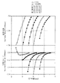
図1について説明すると、このW型分散補償光ファイバ母材1(あるいは、これを用いて製造された分散補償光ファイバ)は、センタコア1aと、該センタコア1aの外周上に設けられてこれより低屈折率のサイドコア1bと、該サイドコア1bの外周上に設けられてセンタコア1aよりも低屈折率かつサイドコア1bよりも高屈折率のクラッド1cとを備えた屈折率分布形状を有している。符号r1は、センタコア1aの軸線からの半径(従い、r1の2倍がセンタコア1aの外径となる)、符号r2は、同軸線からのサイドコア1bの半径(従い、r2の2倍がサイドコア1bの外径となる)、Δ2はクラッド1cとサイドコア1bとの比屈折率差、Δ1はクラッド1cとセンタコア1aとの比屈折率差を示す。なお、この図1では紙面上方向に向かうほど高屈折率であることを示す。このサイドコア1bの内半径r2を、センタコア1aの半径r1で割った比を、横軸にコア半径、縦軸に波長分散と分散スロープとをとったグラフにプロットしたものが図3である。なお、図3における波長分散及び分散スロープは、全て波長1550nmにおける値を示すものである。本実施例1においては、図3に記述してあるように、Δ1=2.3%、Δ2=−0.40%である。また、r2/r1が2.5〜4.5の範囲であれば前述の諸特性を良好に得ることができることが分かる。
【0021】
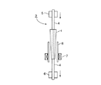
このW型分散補償光ファイバ母材1を、図5のようにテーパ状に加工し、次いで図6のような延伸装置3で同じファイバ外径125μmになるように線引きして分散補償光ファイバ(図示せず)を得た。このときの一方の端のコア径(r2×2)が4.3μm、他方の端のコア径(r2×2)が4.05μmであった。なお、図6の符号4はダミーのロッドであり、符号5は上部チャックであり、符号6は下部チャックであり、符号7は加熱炉であり、符号8は炉心管である。
【0022】
作製された前記分散補償光ファイバは、全長7.35kmであり、全長での1.55μmにおける伝送損失が0.45dB/km、波長分散が−125ps/nm/km、分散スロープが−0.40ps/nm2 /kmである。これを波長分散が+17ps/nm/km、分散スロープが+0.06ps/nm2 /kmの1.3μm帯伝送用シングルモード光ファイバ54kmと接続して使用すると、伝送路全体での波長分散は略零となり、分散スロープは伝送路全体で0.30ps/nm2 、単位長さ当たりに換算して+0.005ps/nm2 /kmと低分散スロープな伝送路を構築することができた。また、この分散補償光ファイバを、胴径60mmのアルミリールに巻いて小型コイル状に巻き込んだが、このとき、コア径が大きくて曲げ特性の強い方から巻いたので、曲げ損失特性が劣化せず、コイル自体の曲げ損失特性も劣化しなかった。そのため、1.55μm帯において1.3μm帯伝送用シングルモード光ファイバに接続して波長1.55μmでの分散補償を行ったとき、波長1.53μm〜1.61μmの広帯域で分散が殆ど零であり、低損失で、広帯域での分散が小さいため、良好な伝送を行うことができた。
【0023】
[実施例2]
VAD法によりGeO2添加コア−SiO2クラッド構造を有する多孔質体を作製した。この多孔質体をおよそ1000℃の雰囲気においてHeと塩素系ガスで脱水処理し、その後、5l/minのHeと1000cc/minのSiF4の雰囲気でフッ素添加及び透明ガラス化を同時に行った。このロッドを延伸してコア母材とし、その周りにリング部分を形成するGeO2−SiO2からなる多孔質体とクラッディング用のSiO2からなる多孔質体を順次外付けし、およそ1000℃の雰囲気においてHeと塩素系ガスで脱水処理し、さらに、He雰囲気で透明ガラス化して図2に示すようなプロファイル(屈折率分布)を有する分散補償光ファイバ母材を作製した。
図2について説明すると、分散補償光ファイバ母材2は、センタコア2aと、該センタコア2aの外周上に設けられてこれより低屈折率のサイドコア2bと、該サイドコア2bの外周上に設けられてこれよりも高屈折率かつセンタコア2aよりも低屈折率のリング層2cと、該リング層2cの外周上に設けられてセンタコア2aとリング層2cよりも低屈折率かつサイドコア2bよりも高屈折率のクラッド2dとを備えた屈折率分布形状を有している。
符号r21は、センタコア2aの軸線からの半径(従い、r21の2倍がセンタコア2aの外径となる)、符号r22は、同軸線からサイドコア2bの半径(従い、r22の2倍がサイドコア2bの外径となる)、符号r23は、同軸線からリング層2cの半径(従い、r23の2倍がリング層2cの外径となる)、△21はクラッド2dとセンタコア2aとの比屈折率差、△22はクラッド2dとサイドコア2bとの比屈折率差、△23はクラッド2dとリング層2cとの比屈折率差を示す。なお、この図2では紙面上方向に向かうほど高屈折率であることを示す。
サイドコア2bの内半径r22を、センタコア2aの半径r21で割った比を、横軸にコア半径、縦軸に波長分散と分散スロープとをとったグラフにプロットしたものが図4である。なお、図4における波長分散及び分散スロープは、全て波長1550nmにおける値を示すものである。本実施例2においては、図4に記述してあるように、△21=2.3%、△22=−0.40%、△23=0.4%、r23−r22=2r21である。また、r22/r21は4.5とした。更に、図4から、r22/r21が2.5〜4.5の範囲であれば、前述の諸特性を良好に得ることができることが分かる。
【0024】
この分散補償光ファイバ母材1を、実施例1の図5のようにテーパ状に加工し、次いで前記延伸装置3でファイバ外径125μmになるように線引きして分散補償光ファイバ(図示せず)を得た。このときの一方の端のコア径(r23×2)が5.1μm、他方の端のコア径(r23×2)が5.3μmであった。
【0025】
作製された前記分散補償光ファイバは、全長4.0kmであり、全長での1.55μmにおける伝送損失が0.45dB/km、波長分散が−135ps/nm/km、分散スロープが−0.44ps/nm2 /kmである。これを波長分散が+17ps/nm/km、分散スロープが+0.06ps/nm2 /kmの1.3μm帯伝送用シングルモード光ファイバ31.8kmと接続して使用すると、伝送路全体での波長分散は略零となり、分散スロープは伝送路全体で0.15ps/nm2 、単位長さ当たりに換算して+0.004ps/nm2 /kmと低分散スロープな伝送路を構築することができた。また、この分散補償光ファイバを、胴径60mmのアルミリールに巻いて小型コイル状に巻き込んだが、このとき、コア径が大きくて曲げ特性の強い方から巻いたので、曲げ損失特性が劣化せず、コイル自体の曲げ損失特性も劣化しなかった。そのため、1.55μm帯において1.3μm帯伝送用シングルモード光ファイバに接続して波長1.55μmでの分散補償を行ったとき、波長1.53μm〜1.61μmの広帯域で分散が殆ど零であり、低損失で、広帯域での分散が小さいため、良好な伝送を行うことができた。
【0026】
[比較例1]
上記実施例1と同様に、VAD法によりGeO2添加コア−SiO2クラッド構造を有する多孔質体を作製した。この多孔質体をおよそ1000℃の雰囲気においてHeと塩素系ガスで脱水処理し、その後、5l/minのHeと1000cc/minのSiF4の雰囲気でフッ素添加及び透明ガラス化を同時に行った。このロッドを延伸してコア母材とし、その周りにクラッディング用のSiO2からなる多孔質体を外付けし、およそ1000℃の雰囲気においてHeと塩素系ガスで脱水処理し、さらに、He雰囲気で透明ガラス化して、実施例1と同じプロファイル(屈折率分布)を有する別のW型分散補償光ファイバ母材を作製した(図示せず)。
【0027】
このW型分散補償光ファイバ母材をコア径=4.3μm、ファイバ外径=125μmとなるように線引きして分散補償光ファイバを得た。作製された分散補償光ファイバは、1.55μmにおいて伝送損失が0.45dB/km、波長分散が−100ps/nm/km、分散スロープが−0.13ps/nm2 /kmであったため、実施例1と同じ1.3μm帯伝送用シングルモード光ファイバに接続して波長1.55μmでの分散補償を行ったとき、残留分散スロープが+0.032ps/nm2 /km程度残ったため、さらに波長毎の分散補償が必要となった。また、この分散補償光ファイバを胴径60mmのアルミリールに巻いて小型のコイルにしても曲げ損失特性は劣化しなかった。
【0028】
[比較例2]
上記実施例1と同様に、VAD法によりGeO2添加コア−SiO2クラッド構造を有する多孔質体を作製した。この多孔質体をおよそ1000℃の雰囲気においてHeと塩素系ガスで脱水処理し、その後、5l/minのHeと1000cc/minのSiF4の雰囲気でフッ素添加及び透明ガラス化を同時に行った。このロッドを延伸してコア母材とし、その周りにクラッディング用のSiO2からなる多孔質体を外付けし、およそ1000℃の雰囲気においてHeと塩素系ガスで脱水処理し、さらに、He雰囲気で透明ガラス化して実施例1と同じプロファイルを有する別のW型分散補償光ファイバ母材(図示せず)を作製した。
【0029】
このW型分散補償光ファイバ母材をコア径=4.1μm、ファイバ外径=125μmとなるように線引きして分散補償光ファイバを得た。作製された分散補償光ファイバは、1.55μmにおける伝送損失が0.45dB/km、波長分散が−133ps/nm/km、分散スロープが−0.42ps/nm2 /kmであったので、実施例1と同じ1.3μm帯伝送用シングルモード光ファイバに接続して波長1.55μmでの分散補償を行ったとき、波長1.53μmから1.61μmの広帯域で分散が殆ど零となり、分散スロープは伝送路全体で単位長さ当たりに換算して+0.006ps/nm2 /kmと低分散スロープであり、良好な伝送を行うことができた。しかし、この分散補償光ファイバを胴径60mmのアルミリールに巻いて小型のコイルにすると急激に曲げ損失特性が劣化し、コイル自体の曲げ損失特性が悪化した。そのため、良好な伝送を行うことができなくなった。
【0030】
[比較例3]
VAD法によりGeO2添加コア−SiO2クラッド構造を有する多孔質体を作製した。この多孔質体をおよそ1000℃の雰囲気においてHeと塩素系ガスで脱水処理し、その後、5l/minのHeと1000cc/minのSiF4の雰囲気でフッ素添加及び透明ガラス化を同時に行った。このロッドを延伸してコア母材とし、その周りにリング部分を形成するGeO2−SiO2からなる多孔質体とクラッディング用のSiO2からなる多孔質体を順次外付けし、およそ1000℃の雰囲気においてHeと塩素系ガスで脱水処理し、さらに、He雰囲気で透明ガラス化して実施例2と同じプロファイルを有する分散補償光ファイバ母材を作製した。
【0031】
このW型分散補償光ファイバ母材をコア径=5.15μm、ファイバ外径=125μmとなるように線引きして分散補償光ファイバを得た。作製された分散補償光ファイバは、全長4.0kmであり、全長での1.55μmにおける伝送損失が0.45dB/km、波長分散が−135ps/nm/km、分散スロープが−0.44ps/nm2 /kmであった。これを、実施例2と同じ1.3μm帯伝送用シングルモード光ファイバと接続して使用すると、伝送路全体での波長分散は略零であり、分散スロープは伝送路全体で0.15ps/nm2 、単位長さ当たりに換算して+0.004ps/nm2 /kmと低分散スロープな伝送路を構築することができた。しかし、この分散補償光ファイバを胴径60mmのアルミリールに巻いて小型のコイルにすると急激に曲げ損失特性が劣化し、コイル自体の曲げ損失特性が悪化した。そのため、良好な伝送を行うことができなくなった。
【0032】
したがって、以上に説明したように、上記比較例1の分散補償光ファイバでは更なる波長毎の分散補償が必要となり、また、上記比較例2及び上記比較例3の分散補償光ファイバではこれを小型のコイルにすると急激に曲げ損失特性が劣化してコイル自体の曲げ損失特性が悪化することとなった。これに対し、本発明の構成から成る上記実施例の分散補償光ファイバでは、これを巻いて小型コイルにしても曲げ損失特性が劣化せず、コイル自体の曲げ損失特性も劣化することがなかった。これにより、1.55μm帯において1.3μm用シングルモード光ファイバに接続した場合においても、広帯域で分散が殆ど零であり、低損失で、良好な伝送を行えるという優れた性能を得ることが可能となった。
【0033】
【発明の効果】
以上説明したように、本発明の請求項1〜5記載の分散補償光ファイバ及びその製造方法によれば、1.53〜1.61μmから選択される使用波長帯における波長分散が−80ps/nm/km以下であり、かつ分散スロープが0ps/nm2 /km以下であり、かつその使用長において実質的にシングルモード伝搬可能なカットオフ波長を有する1本の分散補償光ファイバから構成され、その長手方向における分散スロープが0〜−1.0ps/nm2 /kmの範囲で変化し、前記分散スロープが径方向内側から外側に向かって小さくなるように前記小型コイル状に巻かれている構成を採用したことにより、分散スロープ補償効果が高く、かつ小型コイル状に巻き込んでも伝送損失特性の劣化が荘司ない分散補償光ファイバを容易に製造することが可能となった。
【0034】
また、上記請求項6記載の光ファイバ型分散補償器によれば、分散スロープ補償効果が高く、かつ小型コイルに巻き込んでも伝送損失特性の劣化が生じない分散補償光ファイバを採用したことにより、小型化が可能な光ファイバ型分散補償器を容易に製造することが可能となった。
【図面の簡単な説明】
【図1】 本発明の実施例1で用いられる分散補償光ファイバの屈折率分布を示すグラフである。
【図2】 本発明の実施例2で用いられる分散補償光ファイバの屈折率分布を示すグラフである。
【図3】 実施例1の分散補償光ファイバのコア径を変化させたときの分散特性図である。
【図4】 実施例1の分散補償光ファイバのコア径を変化させたときの分散特性図である。
【図5】 実施例1で用いられるテーパ状ロッドを示す図であって、軸線を通る断面での断面図である。
【図6】 実施例1及び実施例2で用いられる延伸装置の概略説明図である。
【符号の説明】
1a、2a・・・センタコア、1b、2b・・・サイドコア、1c、2d・・・クラッド、2c・・・リング層[0001]
BACKGROUND OF THE INVENTION
The present invention relates to a dispersion-compensating optical fiber and an optical fiber-type dispersion compensator, and more particularly to a dispersion-compensating optical fiber and an optical fiber-type dispersion compensator that can be miniaturized while compensating for a dispersion slope for wavelength division multiplexing transmission. is there.
[0002]
[Prior art]
With the advent of erbium (Er) doped optical fiber amplifiers, systems using optical amplifiers such as ultra-long-distance non-regenerative repeaters and optical subscriber multi-distribution networks in the 1.55 μm band are being actively studied for practical use. Yes.
Assuming high-speed transmission, it is desirable to use a 1.55 μm dispersion-shifted fiber that has a wavelength dispersion value of 1.55 μm and a chromatic dispersion value that is small for these transmission lines. When transmission is performed in the 1.55 μm wavelength band, a large chromatic dispersion occurs and the optical signal deteriorates. Therefore, technical means for suppressing this chromatic dispersion is necessary when transmission is performed in the 1.55 μm wavelength band using a 1.3 μm band single mode optical fiber. As one of the technical means, there is a method of compensating a chromatic dispersion value in a wavelength of 1.55 μm band by using a dispersion compensating optical fiber having a wavelength dispersion having a sign opposite to that of a 1.3 μm band single mode optical fiber.
[0003]
In addition, when performing WDM transmission using a 1.55 μm band dispersion-shifted fiber, if the chromatic dispersion in the operating wavelength band is small, a phenomenon of four-wave mixing, which is one of nonlinear effects, occurs, and transmission characteristics deteriorate. Problems arise. In order to suppress this non-linear effect, a transmission method for transmitting 1.55 μm using a 1.3 μm band single mode optical fiber and a dispersion compensating optical fiber has been proposed from the beginning.
Dispersion compensation methods using optical fiber include a dispersion compensation optical fiber with a single-peak structure with a large relative refractive index difference, and dispersion compensation with a double clad refractive index profile structure that enables dispersion slope compensation. Several proposals, such as a method using an optical fiber, have been made.
This dispersion-compensating optical fiber is incorporated into the device in use, like a rare-earth-doped optical fiber for optical amplification that compensates for transmission path loss, so it is usually a small coil wound around a small reel. Used as a module.
[0004]
[Problems to be solved by the invention]
However, this dispersion-compensating optical fiber needs to be designed where the bending is relatively weak (where the dispersion slope value is small) in order to increase the dispersion value per unit length and take a large dispersion slope on the minus side. is there. In particular, in order to obtain a large dispersion slope compensation on the minus side, the refractive index distribution structure is very weak against bending. This dispersion compensating optical fiber having a high dispersion slope compensation effect has a small transmission loss when it is not bent to a small radius of curvature. However, when it is wound around a small reel for modularization, there is a problem that the transmission loss becomes large. It will be. For this reason, it has been extremely difficult to manufacture a dispersion compensating optical fiber that has a high dispersion slope compensation effect and that does not cause deterioration in transmission loss characteristics even when wound on a small reel. For this reason, it is conceivable that the coil body diameter is increased and the coil is wound with a diameter that does not cause deterioration of the bending loss characteristics. However, since the winding volume is increased, there is a problem that it is difficult to reduce the size of the module. Become.
[0005]
The dispersion compensating optical fiber and the optical fiber type dispersion compensator of the present invention have been made in view of the above circumstances, and have the following objects.
That is, an object of the present invention is to provide a dispersion compensating optical fiber and an optical fiber type dispersion compensator that have a high dispersion slope compensation effect and that do not cause deterioration in transmission loss characteristics even when they are wound into a small coil.
[0006]
[Means for Solving the Problems]
The dispersion compensating optical fiber and the optical fiber type dispersion compensator of the present invention employ the following means in order to solve the above problems. That is, the dispersion compensating optical fiber according to
[0007]
A dispersion compensating optical fiber according to
[0008]
The dispersion compensating optical fiber according to
[0009]
The dispersion compensating optical fiber according to claim 4.Manufacturing methodIsA dispersion compensating optical fiber wound as a small coil and used as an optical fiber type dispersion compensator, and having a wavelength dispersion of −80 ps / nm / km or less in a used wavelength band selected from 1.53 to 1.61 μm Yes, and dispersion slope is 0ps / nm 2 / Dispersion-compensating optical fiber having a cut-off wavelength that can be propagated in a single mode substantially in its use length, and the dispersion slope in the longitudinal direction is 0 to −1.0 ps / nm 2 In the dispersion compensating optical fiber wound in the small coil shape so that the dispersion slope decreases from the radially inner side to the outer side, and the base material is uniform in the longitudinal direction. It is characterized by comprising at least a step of drawing the base material into a tapered shape after manufacturing and then drawing so as to form a constant optical fiber diameter.
Furthermore, the dispersion compensating optical fiber manufacturing method according to
[0010]
Also,Claim 6The described optical fiber type dispersion compensator,smallIn an optical fiber type dispersion compensator having a dispersion compensating optical fiber wound in a coil shape,ReportThe dispersion compensating optical fiber is used in a wavelength band selected from 1.53 to 1.61 μm.InChromatic dispersion is -80 ps / nm / km or less, and dispersion slowIs0 ps / nm2/ Km or less, and has a cut-off wavelength capable of substantially single-mode propagation over the length of use.Comprising a single dispersion compensating optical fiberLongitudinal directionInDistributed throwIs0 to -1.0ps / nm2In the range of / kmThe dispersion slope is wound in the small coil shape so that the dispersion slope decreases from the inner side to the outer side in the radial direction.The residual wavelength component in the used wavelength band selected from 1.53 to 1.61 μm when connected to a single mode optical fiber for 1.3 μm band transmission.Scatter-8 to +8 ps / nm / km, and residual dispersion slope is -0.03 to +0.03 ps / nm2/ Km.
[0011]
The dispersion compensating optical fiber according to claim 1 andClaim 6According to the optical fiber type dispersion compensator, the dispersion compensating optical fiber is, MinutesScattered throwIsThe larger one is more resistant to bending,MinScattered throwIsThe smaller one is vulnerable to bending, so the dispersion throw is relatively strong against bending.IsThe larger one is the winding start part with a smaller bending diameter, and the dispersion throw is relatively weak against bending.IssmallNoThis is wound as an outer peripheral portion having a larger bending diameter. This makes it possible to configure a small coil with a single optical fiber while maintaining the dispersion slope compensation rate.
[0012]
DETAILED DESCRIPTION OF THE INVENTION
An embodiment of the dispersion compensating optical fiber of the present invention and an optical fiber type dispersion compensator provided with the same will be described, but the present invention is of course not limited thereto.
[0013]
The dispersion compensating optical fiber of the present embodiment is used as an optical fiber type dispersion compensator by being wound in a small coil shape, and has a 1.55 μm band (a used wavelength band selected from 1.53 to 1.61 μm). Chromatic dispersion at -80 ps / nm / km or less and a dispersion slope value of 0 ps / nm2/ Km or less, and has a refractive index distribution (refractive index distribution shown in FIGS. 1 and 2 to be described later) structure having a cutoff wavelength that can propagate substantially in a single mode in the use length, and in the longitudinal direction. Dispersion slope value of 0 to -1.0 ps / nm2The structure which changes in the range of / km is adopted. Furthermore, when winding the dispersion compensating optical fiber, a winding method is adopted in which the dispersion slope value is reduced to a small coil shape so that the dispersion slope value decreases from the radially inner side to the outer side.
[0014]
That is, the dispersion compensating optical fiber of the present embodiment has a dispersion slope value of 0 to −1.0 ps / nm in the longitudinal direction in at least one wavelength in the 1.55 μm band, that is, in the range of 1.53 μm to 1.61 μm.2A dispersion compensating optical fiber that is changing in the range of / km is manufactured, and the part that starts to be wound around the body is made a part having a relatively low dispersion slope compensation effect and a strong bending characteristic, and the part toward the outer periphery has a relatively bending characteristic. A dispersion compensating optical fiber that is weak and has a high dispersion slope compensation effect to achieve a high dispersion slope compensation effect as a whole is intended to be realized by a single optical fiber instead of a plurality of connections.
[0015]
As a means for changing the characteristics in the longitudinal direction, as in Example 1 to be described later, before drawing, the base material is processed into a tapered shape and then drawn with a constant optical fiber diameter. A base material having a constant outer diameter may be drawn so that the diameter changes in a tapered shape. That is, even if the refractive index distribution shape is the same, it is possible to change the dispersion slope together with the chromatic dispersion by changing the core diameter. In this case, since the bending loss is larger when the dispersion slope is smaller, that is, when the core diameter is smaller, it is preferably used on the fiber outer peripheral side where the bending diameter can be naturally increased when coiled. As a method of changing the core diameter, after manufacturing a uniform base material in the longitudinal direction, the processing described in the first embodiment is performed, and then the core diameter is drawn with a constant diameter so that the outer diameter is constant and the core An optical fiber having a changed diameter can be manufactured. It can also be produced by manufacturing a uniform base material in the longitudinal direction and then changing the outer diameter of the fiber during drawing.
[0016]
In addition, as an optical fiber type dispersion compensator including such a dispersion compensating optical fiber, a dispersion compensating optical fiber wound in a small coil shape is connected to a 1.3 μm band single mode optical fiber, Use wavelength band selected from 1.53 to 1.61 μmInResidual wavelengthScatter-8 to +8 ps / nm / km, and residual dispersion slope is -0.03 to +0.03 ps / nm2/ Km is preferable from the viewpoint of achieving both a reduction in the size of the dispersion compensator and an improvement in transmission characteristics in a wide band.
[0017]
By adopting the configuration described above, it is possible to easily manufacture a dispersion compensating optical fiber that has a high dispersion slope compensation effect and does not cause deterioration in transmission loss characteristics even when it is wound into a small coil.
Therefore, by adopting a dispersion compensating optical fiber that has a high dispersion slope compensation effect and does not cause deterioration of transmission loss characteristics even if it is wound in a small coil shape, an optical fiber type dispersion compensator that can be reduced in size can be easily obtained. It can also be manufactured.
[0018]
Embodiments of the present invention will be described below with reference to the drawings.
1 is a graph showing the refractive index distribution of the dispersion compensating optical fiber used in Example 2, FIG. 2 is a graph showing the refractive index distribution of Example 1, FIG. 4 is Example 1 and FIG. FIG. 5 is a dispersion characteristic diagram when the core diameter of the dispersion compensating optical fiber is changed, FIG. 5 is an explanatory diagram of a tapered rod used in the first embodiment, and FIG. 6 is used in the first and second embodiments. It is a schematic explanatory drawing of an extending | stretching apparatus.
[0019]
[Example 1]
The dispersion compensating
First, GeO is obtained by the VAD method.2Addition core-SiO2A porous body having a cladding structure was produced. The porous body was dehydrated with He and a chlorine-based gas in an atmosphere of about 1000 ° C., and then 5 l / min He and 1000 cc / min SiF.FourIn the atmosphere, fluorine addition and transparent vitrification were simultaneously performed. This rod is stretched to form a core base material around which SiO2 is used for cladding.21 is attached to the outside, dehydrated with He and a chlorine-based gas in an atmosphere of approximately 1000 ° C., and further converted into transparent glass in the He atmosphere to have a profile (refractive index distribution) as shown in FIG. Type dispersion compensating optical fiber preform was fabricated.
[0020]
Referring to FIG. 1, this W-type dispersion compensating optical fiber preform 1 (or a dispersion compensating optical fiber manufactured using the same) is provided on the outer periphery of the
[0021]
This W-type dispersion compensating
[0022]
The produced dispersion-compensating optical fiber has a total length of 7.35 km, a transmission loss at a total length of 1.55 μm of 0.45 dB / km, a chromatic dispersion of −125 ps / nm / km, and a dispersion slow.Is-0.40ps / nm2/ Km. This has a chromatic dispersion of +17 ps / nm / km and a dispersion slope of +0.06 ps / nm.2/ Km 1.3μm bandFor transmissionWhen used in connection with a single mode optical fiber 54 km, the chromatic dispersion in the entire transmission line is substantially zero, and the dispersion slope is 0.30 ps / nm in the entire transmission line.2+ 0.005ps / nm in terms of unit length2/ Km and a low dispersion slope transmission line can be constructed.The. In addition, this dispersion compensating optical fiber is wound around an aluminum reel having a body diameter of 60 mm and wound into a small coil shape. At this time, since the core diameter is large and the winding characteristic is strong, the bending loss characteristic is not deteriorated. The bending loss characteristics of the coil itself did not deteriorate. Therefore, 1.3μm in the 1.55μm bandBand transmissionWhen dispersion compensation is performed at a wavelength of 1.55 μm by connecting to a single-mode optical fiber, the dispersion is almost zero in a wide band of wavelengths from 1.53 μm to 1.61 μm, low loss, and dispersion in a wide band is small Therefore, good transmission could be performed.
[0023]
[Example 2]
GeO by VAD method2Addition core-SiO2A porous body having a cladding structure was produced. The porous body was dehydrated with He and a chlorine-based gas in an atmosphere of about 1000 ° C., and then 5 l / min He and 1000 cc / min SiF.FourIn the atmosphere, fluorine addition and transparent vitrification were simultaneously performed. This rod is stretched to be a core base material, and a ring portion is formed around it.2-SiO2Made of porous material and SiO for cladding2A porous body made of the above is sequentially attached, dehydrated with He and a chlorine-based gas in an atmosphere of about 1000 ° C., and further formed into a transparent glass in a He atmosphere to have a profile (refractive index distribution) as shown in FIG. A dispersion-compensating optical fiber preform was prepared.
Referring to FIG. 2, the dispersion compensating
The symbol r21 is a radius from the axis of the
FIG. 4 is a graph in which the ratio obtained by dividing the inner radius r22 of the
[0024]
The dispersion-compensating
[0025]
The produced dispersion compensating optical fiber has a total length of 4.0 km, a transmission loss of 0.45 dB / km at a total length of 1.55 μm, a chromatic dispersion of −135 ps / nm / km, and a dispersion slow.Is-0.44ps / nm2/ Km. This has a chromatic dispersion of +17 ps / nm / km and a dispersion slope of +0.06 ps / nm.2/ Km 1.3μm bandFor transmissionWhen used in connection with a single mode optical fiber of 31.8 km, the chromatic dispersion in the entire transmission line is substantially zero, and the dispersion slope is 0.15 ps / nm in the entire transmission line.2+ 0.004ps / nm in terms of unit length2/ Km and a low dispersion slope transmission line could be constructed. In addition, this dispersion compensating optical fiber is wound around an aluminum reel having a body diameter of 60 mm and wound into a small coil shape. At this time, since the core diameter is large and the winding characteristic is strong, the bending loss characteristic is not deteriorated. The bending loss characteristics of the coil itself did not deteriorate. Therefore, 1.3μm in the 1.55μm bandBand transmissionWhen dispersion compensation is performed at a wavelength of 1.55 μm by connecting to a single-mode optical fiber, the dispersion is almost zero in a wide band of wavelengths from 1.53 μm to 1.61 μm, low loss, and dispersion in a wide band is small Therefore, good transmission could be performed.
[0026]
[Comparative Example 1]
Similar to Example 1 above, GeO was obtained by the VAD method.2Addition core-SiO2A porous body having a cladding structure was produced. The porous body was dehydrated with He and a chlorine-based gas in an atmosphere of about 1000 ° C., and then 5 l / min He and 1000 cc / min SiF.FourIn the atmosphere, fluorine addition and transparent vitrification were simultaneously performed. This rod is stretched to form a core base material around which SiO2 is used for cladding.2A porous body made of the above is externally attached, dehydrated with He and a chlorine-based gas in an atmosphere of about 1000 ° C., and further transparently vitrified in an He atmosphere to have the same profile (refractive index distribution) as in Example 1. W-type dispersion compensating optical fiber preform (not shown) was prepared.
[0027]
This W-type dispersion compensating optical fiber preform was drawn so as to have a core diameter = 4.3 μm and a fiber outer diameter = 125 μm to obtain a dispersion compensating optical fiber. The produced dispersion-compensating optical fiber has a transmission loss of 0.45 dB / km, a chromatic dispersion of −100 ps / nm / km, a dispersion slow at 1.55 μm.Is-0.13ps / nm2/ Km, the same 1.3 μm as in Example 1.Band transmissionResidual dispersion slope is +0.032 ps / nm when dispersion compensation is performed at a wavelength of 1.55 μm when connected to a single mode optical fiber2Since about / km remained, dispersion compensation for each wavelength was further required. Further, even when this dispersion compensating optical fiber is wound around an aluminum reel having a body diameter of 60 mm and a small coil is used, the bending loss characteristics are not deteriorated.
[0028]
[Comparative Example 2]
Similar to Example 1 above, GeO was obtained by the VAD method.2Addition core-SiO2A porous body having a cladding structure was produced. The porous body was dehydrated with He and a chlorine-based gas in an atmosphere of about 1000 ° C., and then 5 l / min He and 1000 cc / min SiF.FourIn the atmosphere, fluorine addition and transparent vitrification were simultaneously performed. This rod is stretched to form a core base material around which SiO2 is used for cladding.2Another W-type dispersion compensation light having the same profile as that of Example 1 is obtained by externally attaching a porous body made of the above, dehydrating with He and a chlorine-based gas in an atmosphere of approximately 1000 ° C., and further forming a transparent glass in the He atmosphere. A fiber preform (not shown) was produced.
[0029]
This W-type dispersion compensating optical fiber preform was drawn so as to have a core diameter = 4.1 μm and a fiber outer diameter = 125 μm to obtain a dispersion compensating optical fiber. The manufactured dispersion compensating optical fiber is 1.55 μm.KickTransmission loss is 0.45dB / km, chromatic dispersion is -133ps / nm / km, dispersion slowIs-0.42ps / nm2/ Km, the same 1.3 μm as in Example 1.Band transmissionWhen dispersion compensation is performed at a wavelength of 1.55 μm when connected to a single-mode optical fiber, the dispersion is almost zero over a wide band from 1.53 μm to 1.61 μm, and the dispersion slope per unit length of the entire transmission line Converted to + 0.006ps / nm2/ Km and low dispersion slope, and good transmission could be performed. However, when this dispersion-compensating optical fiber is wound on an aluminum reel having a body diameter of 60 mm to form a small coil, the bending loss characteristic deteriorates rapidly, and the bending loss characteristic of the coil itself deteriorates. As a result, good transmission cannot be performed.
[0030]
[Comparative Example 3]
GeO by VAD method2Addition core-SiO2A porous body having a cladding structure was produced. The porous body was dehydrated with He and a chlorine-based gas in an atmosphere of about 1000 ° C., and then 5 l / min He and 1000 cc / min SiF.FourIn the atmosphere, fluorine addition and transparent vitrification were simultaneously performed. This rod is stretched to be a core base material, and a ring portion is formed around it.2-SiO2Made of porous material and SiO for cladding2The dispersion-compensating optical fiber preform having the same profile as that of Example 2 is obtained by sequentially attaching a porous body made from the above, dehydrating with He and a chlorine-based gas in an atmosphere of approximately 1000 ° C., and further forming a transparent glass in the He atmosphere. Was made.
[0031]
This W-type dispersion compensating optical fiber preform was drawn so as to have a core diameter = 5.15 μm and a fiber outer diameter = 125 μm to obtain a dispersion compensating optical fiber. The manufactured dispersion-compensating optical fiber has a total length of 4.0 km, a transmission loss of 0.45 dB / km at a total length of 1.55 μm, a chromatic dispersion of −135 ps / nm / km, and a dispersion slow.Is-0.44ps / nm2/ KmWas. This is the same 1.3 μm band as in Example 2.For transmissionWhen used in connection with a single mode optical fiber, the chromatic dispersion in the entire transmission line is substantially zero, and the dispersion slope is 0.15 ps / nm in the entire transmission line.2+ 0.004ps / nm in terms of unit length2/ Km and a low dispersion slope transmission line could be constructed. However, when this dispersion-compensating optical fiber is wound on an aluminum reel having a body diameter of 60 mm to form a small coil, the bending loss characteristic deteriorates rapidly, and the bending loss characteristic of the coil itself deteriorates. As a result, good transmission cannot be performed.
[0032]
Therefore, as described above, the dispersion compensation optical fiber of Comparative Example 1 requires further dispersion compensation for each wavelength, and the dispersion compensation optical fibers of Comparative Example 2 and Comparative Example 3 are small in size. When this coil was used, the bending loss characteristics deteriorated rapidly, and the bending loss characteristics of the coil itself deteriorated. On the other hand, in the dispersion compensating optical fiber according to the above-described embodiment having the configuration of the present invention, even if it is wound around a small coil, the bending loss characteristic does not deteriorate, and the bending loss characteristic of the coil itself does not deteriorate. . As a result, even when connected to a 1.3 μm single-mode optical fiber in the 1.55 μm band, it is possible to obtain excellent performance such that broadband and almost zero dispersion, low loss, and good transmission can be achieved. It became.
[0033]
【The invention's effect】
As described above, claims 1 to 1 of the present invention.5Dispersion compensating optical fiber as describedAnd its manufacturing methodAccording to the wavelength band selected from 1.53 to 1.61 μmInChromatic dispersion is -80 ps / nm / km or less, and dispersion slowIs0 ps / nm2/ Km or less, and has a cut-off wavelength capable of substantially single-mode propagation over the length of use.Comprising a single dispersion compensating optical fiberLongitudinal directionInDistributed throwIs0 to -1.0ps / nm2Change in the range of / kmAnd the dispersion slope is wound in the small coil shape so as to decrease from the radially inner side to the outer side.Adopting the configurationByIt has become possible to easily manufacture a dispersion compensating optical fiber that has a high dispersion slope compensation effect and that does not deteriorate transmission loss characteristics even when it is wound into a small coil.
[0034]
In addition, the above claims6According to the described optical fiber type dispersion compensator, it is possible to reduce the size of the optical fiber by adopting the dispersion compensating optical fiber that has a high dispersion slope compensation effect and that does not cause deterioration of transmission loss characteristics even if it is wound around a small coil. Type dispersion compensator can be easily manufactured.
[Brief description of the drawings]
FIG. 1 is a graph showing a refractive index distribution of a dispersion compensating optical fiber used in Example 1 of the present invention.
FIG. 2 is a graph showing a refractive index distribution of a dispersion compensating optical fiber used in Example 2 of the present invention.
FIG. 3 is a dispersion characteristic diagram when the core diameter of the dispersion compensating optical fiber of Example 1 is changed.
FIG. 4 is a dispersion characteristic diagram when the core diameter of the dispersion compensating optical fiber of Example 1 is changed.
FIG. 5 is a view showing a tapered rod used in Example 1, and is a cross-sectional view taken along a cross section along an axis.
6 is a schematic explanatory diagram of a stretching apparatus used in Example 1 and Example 2. FIG.
[Explanation of symbols]
1a, 2a ... center core, 1b, 2b ... side core, 1c, 2d ... clad, 2c ... ring layer
Claims (6)
1.53〜1.61μmから選択される使用波長帯における波長分散が−80ps/nm/km以下であり、かつ分散スロープが0ps/nm2 /km以下であり、かつその使用長において実質的にシングルモード伝搬可能なカットオフ波長を有する1本の分散補償光ファイバから構成され、その長手方向における分散スロープが0〜−1.0ps/nm2 /kmの範囲で変化し、前記分散スロープが径方向内側から外側に向かって小さくなるように前記小型コイル状に巻かれていることを特徴とする分散補償光ファイバ。A dispersion compensating optical fiber wound as a small coil and used as an optical fiber type dispersion compensator ,
Wavelength dispersion in the used wavelength band selected from 1.53~1.61μm is not more than -80 ps / nm / miles, and the dispersion slope is not more 0ps / nm 2 / km or less, and substantially in the used length Single-mode propagation can be configured to cut-off wavelength from one of the dispersion compensating optical fiber for chromatic, varies in the range of the dispersion slope is 0~-1.0ps / nm 2 / km in the longitudinal direction, the dispersion The dispersion compensating optical fiber , wherein the slope is wound in the small coil shape so that the slope becomes smaller from the inside in the radial direction toward the outside .
センタコア(1a)と、該センタコアの外周上に設けられてこれより低屈折率のサイドコア(1b)と、サイドコアの外周上に設けられて前記センタコアよりも低屈折率かつ前記サイドコアよりも高屈折率のクラッド(1c)とを備えた屈折率分布形状を有することを特徴とする分散補償光ファイバ。The dispersion compensating optical fiber according to claim 1, wherein
A center core (1a), a side core (1b) provided on the outer periphery of the center core and having a lower refractive index than the center core, and a lower refractive index provided on the outer periphery of the side core than the center core and having a higher refractive index than the side core. A dispersion-compensating optical fiber having a refractive index distribution shape including a clad (1c).
センタコア(2a)と、該センタコアの外周上に設けられてこれより低屈折率のサイドコア(2b)と、該サイドコアの外周上に設けられてこれよりも高屈折率かつ前記センタコアよりも低屈折率のリング層(2c)と、該リング層の外周上に設けられて前記センタコアと前記リング層よりも低屈折率かつ前記サイドコアよりも高屈折率のクラッド(2d)とを備えた屈折率分布形状を有することを特徴とする分散補償光ファイバ。The dispersion compensating optical fiber according to claim 1, wherein
A center core (2a), a side core (2b) provided on the outer periphery of the center core and having a lower refractive index than the center core, and a higher refractive index provided on the outer periphery of the side core and lower than the center core. A refractive index profile comprising: a ring layer (2c); and a center core and a clad (2d) having a lower refractive index than that of the ring layer and a higher refractive index than that of the side core. A dispersion compensating optical fiber characterized by comprising:
長手方向に均一な母材を製造後、予め該母材をテーパ状に加工してから一定の光ファイバ径をなすように線引きする工程を、少なくとも具備したことを特徴とする分散補償光ファイバの製造方法。A dispersion-compensating optical fiber comprising at least a step of drawing a base material uniform in the longitudinal direction and then drawing the base material so as to have a constant optical fiber diameter after processing the base material into a tapered shape in advance. Production method.
長手方向に均一な母材を製造後、線引き時に光ファイバの外径を変化させる工程を、少なくとも具備したことを特徴とする分散補償光ファイバの製造方法。A method for producing a dispersion-compensating optical fiber comprising at least a step of changing an outer diameter of an optical fiber at the time of drawing after producing a base material uniform in the longitudinal direction.
前記分散補償光ファイバは、1.53〜1.61μmから選択される使用波長帯における波長分散が−80ps/nm/km以下であり、かつ分散スロープが0ps/nm2 /km以下であり、かつその使用長において実質的にシングルモード伝搬可能なカットオフ波長を有する1本の分散補償光ファイバから構成され、その長手方向における分散スロープが0〜−1.0ps/nm2 /kmの範囲で変化し、前記分散スロープが径方向内側から外側に向かって小さくなるように前記小型コイル状に巻かれており、
1.3μm帯伝送用シングルモード光ファイバに接続された状態で、1.53〜1.61μmから選択される使用波長帯での残留波長分散が−8〜+8ps/nm/kmとされ、かつ残留分散スロープが−0.03〜+0.03ps/nm2 /kmとされていることを特徴とする光ファイバ型分散補償器。In an optical fiber type dispersion compensator having a dispersion compensating optical fiber wound in a small coil shape,
Before SL minute dispersion compensating optical fiber is a chromatic dispersion -80 ps / nm / miles or less in the used wavelength band selected from 1.53~1.61Myuemu, and dispersion slope is 0ps / nm 2 / km or less There, and is composed of one of the dispersion compensating optical fiber to have a substantially single-mode propagation cutoff wavelength in the used length, dispersion slope in the longitudinal direction 0~-1.0ps / nm 2 / km, and the dispersion slope is wound in the small coil shape so as to decrease from the radially inner side to the outer side ,
In a state of being connected to 1.3μm band single mode optical fiber for transmission, dispersion remaining wavelengths in the use wavelength band selected from 1.53~1.61μm is a -8~ + 8ps / nm / km, and optical fiber dispersion compensator you characterized in that the residual dispersion slope is a -0.03~ + 0.03ps / nm 2 / km .
Priority Applications (1)
| Application Number | Priority Date | Filing Date | Title |
|---|---|---|---|
| JP26950699A JP3781925B2 (en) | 1999-09-22 | 1999-09-22 | Dispersion compensating optical fiber and optical fiber type dispersion compensator |
Applications Claiming Priority (1)
| Application Number | Priority Date | Filing Date | Title |
|---|---|---|---|
| JP26950699A JP3781925B2 (en) | 1999-09-22 | 1999-09-22 | Dispersion compensating optical fiber and optical fiber type dispersion compensator |
Publications (2)
| Publication Number | Publication Date |
|---|---|
| JP2001091764A JP2001091764A (en) | 2001-04-06 |
| JP3781925B2 true JP3781925B2 (en) | 2006-06-07 |
Family
ID=17473379
Family Applications (1)
| Application Number | Title | Priority Date | Filing Date |
|---|---|---|---|
| JP26950699A Expired - Fee Related JP3781925B2 (en) | 1999-09-22 | 1999-09-22 | Dispersion compensating optical fiber and optical fiber type dispersion compensator |
Country Status (1)
| Country | Link |
|---|---|
| JP (1) | JP3781925B2 (en) |
Families Citing this family (1)
| Publication number | Priority date | Publication date | Assignee | Title |
|---|---|---|---|---|
| JP2011228541A (en) * | 2010-04-21 | 2011-11-10 | Photonic Science Technology Inc | Method of manufacturing tapered optical fiber |
-
1999
- 1999-09-22 JP JP26950699A patent/JP3781925B2/en not_active Expired - Fee Related
Also Published As
| Publication number | Publication date |
|---|---|
| JP2001091764A (en) | 2001-04-06 |
Similar Documents
| Publication | Publication Date | Title |
|---|---|---|
| US6731848B2 (en) | Dispersion compensating optical fiber | |
| JP4999063B2 (en) | Optical fiber | |
| JP5307114B2 (en) | Optical fiber | |
| US6477306B2 (en) | Dispersion-compensating optical fiber, and, optical transmission line and dispersion-compensating module respectively including the same | |
| US6943935B2 (en) | Dispersion-managed cable for raman-assisted transmission | |
| JP2000356724A (en) | Optical fiber in which color dispersion is compensated | |
| US6937805B2 (en) | Dispersion compensating fiber and dispersion compensating fiber module | |
| JPH1039155A (en) | Dispersion-compensated fiber and light transmission system including that | |
| US6980723B2 (en) | Dispersion-compensating optical fiber and hybrid transmission line | |
| JP2002341157A (en) | Wavelength multiplex transmission line and dispersion compensating optical fiber used for the same | |
| JP3798227B2 (en) | Dispersion compensation optical fiber connection structure | |
| JP2001159721A (en) | Dispersion compensating optical fiber | |
| JP2001296444A (en) | Dispersion compensating optical fiber, optical transmission line and dispersion compensating module | |
| JP3781925B2 (en) | Dispersion compensating optical fiber and optical fiber type dispersion compensator | |
| KR100433297B1 (en) | Optical fiber for wavelength division multiplexing communication | |
| JP4568485B2 (en) | Single mode optical fiber and optical communication system | |
| JP2002062450A (en) | Dispersion compensating optical fiber and optical transmission line | |
| JP3819264B2 (en) | Dispersion compensating optical fiber, dispersion compensating optical fiber module, and composite transmission line | |
| JP3643012B2 (en) | Dispersion compensating optical fiber | |
| JP3756389B2 (en) | Dispersion compensating optical fiber and optical fiber composite transmission line | |
| JP3481568B2 (en) | Dispersion compensating optical fiber and dispersion compensating optical fiber transmission line using the same | |
| US6898361B2 (en) | Dispersion-compensating optical fiber and optical transmission line | |
| JP4216298B2 (en) | Dispersion compensating optical fiber and dispersion compensating optical fiber module | |
| JP2005197940A (en) | Distributed compensation fiber module and fiber-optic transmission path | |
| JP2003270469A (en) | Dispersion-correction fiber with high figure of merit |
Legal Events
| Date | Code | Title | Description |
|---|---|---|---|
| A977 | Report on retrieval |
Free format text: JAPANESE INTERMEDIATE CODE: A971007 Effective date: 20050801 |
|
| A131 | Notification of reasons for refusal |
Free format text: JAPANESE INTERMEDIATE CODE: A131 Effective date: 20050809 |
|
| A521 | Request for written amendment filed |
Free format text: JAPANESE INTERMEDIATE CODE: A523 Effective date: 20051007 |
|
| TRDD | Decision of grant or rejection written | ||
| A01 | Written decision to grant a patent or to grant a registration (utility model) |
Free format text: JAPANESE INTERMEDIATE CODE: A01 Effective date: 20060228 |
|
| A61 | First payment of annual fees (during grant procedure) |
Free format text: JAPANESE INTERMEDIATE CODE: A61 Effective date: 20060308 |
|
| FPAY | Renewal fee payment (event date is renewal date of database) |
Free format text: PAYMENT UNTIL: 20090317 Year of fee payment: 3 |
|
| FPAY | Renewal fee payment (event date is renewal date of database) |
Free format text: PAYMENT UNTIL: 20100317 Year of fee payment: 4 |
|
| LAPS | Cancellation because of no payment of annual fees |