JP3781473B2 - Apparatus for depositing metal from an electrolyte containing metal - Google Patents
Apparatus for depositing metal from an electrolyte containing metal Download PDFInfo
- Publication number
- JP3781473B2 JP3781473B2 JP06317496A JP6317496A JP3781473B2 JP 3781473 B2 JP3781473 B2 JP 3781473B2 JP 06317496 A JP06317496 A JP 06317496A JP 6317496 A JP6317496 A JP 6317496A JP 3781473 B2 JP3781473 B2 JP 3781473B2
- Authority
- JP
- Japan
- Prior art keywords
- film forming
- tank
- steel strip
- film
- deposition
- Prior art date
- Legal status (The legal status is an assumption and is not a legal conclusion. Google has not performed a legal analysis and makes no representation as to the accuracy of the status listed.)
- Expired - Fee Related
Links
Images


Classifications
-
- C—CHEMISTRY; METALLURGY
- C25—ELECTROLYTIC OR ELECTROPHORETIC PROCESSES; APPARATUS THEREFOR
- C25D—PROCESSES FOR THE ELECTROLYTIC OR ELECTROPHORETIC PRODUCTION OF COATINGS; ELECTROFORMING; APPARATUS THEREFOR
- C25D7/00—Electroplating characterised by the article coated
- C25D7/06—Wires; Strips; Foils
- C25D7/0614—Strips or foils
- C25D7/0628—In vertical cells
Landscapes
- Chemical & Material Sciences (AREA)
- Engineering & Computer Science (AREA)
- Chemical Kinetics & Catalysis (AREA)
- Electrochemistry (AREA)
- Materials Engineering (AREA)
- Metallurgy (AREA)
- Organic Chemistry (AREA)
- Electroplating Methods And Accessories (AREA)
- Electrolytic Production Of Metals (AREA)
- Battery Electrode And Active Subsutance (AREA)
Abstract
Description
【0001】
【発明が属する技術分野】
本発明は、鋼ストリップを金属で被覆するための金属を含有している電解液から金属を析出するための装置であって、この装置が互いに垂直に並列して設けられている被膜形成槽から成り、この装置内において上方の転向ローラおよび/または案内ローラから走出する被膜を形成されるべき鋼ストリップがそれぞれ一つの被膜形成槽の相対して垂直に設けられていてかつ陽極板として形成されている二つの外壁間の間隙を通過して下方の転向ローラへと、そしてそこから他の上方の転向ローラおよび/または案内ローラへと案内され、その際それぞれ下方へと或いは上方へと走る鋼ストリップがポンプにより循環して供給される電解液流によりこの鋼ストリップの移動方向に対して反対方向で作用を受け、そしてこの装置において相前後している被膜形成槽のそれぞれ互いに隣接し合っている陽極板が析出室を区画している様式の、金属を含有している電解液から金属を析出するための装置に関する。
【0002】
【従来の技術】
このような様式の装置はヨーロッパ特許第0 196 420号から公知である。下方へと走る鋼ストリップ部分および上方へと走る鋼ストリップ部分のための陽極−陰極室、即ち析出室を形成している陽極を巡って別個のハウジングが設けられており、これらのハウジング内において電解液流が外方ハウジングのハウジング壁と陽極間の空域内に設けられている液体噴射ポンプを介して別個に循環運動している。鋼ストリップ走行方向と反対方向で高い速度で電解液流が供給されることにより、電解析出を促進する可能な限り乱流状態の向流が発生される。両陽極対を囲繞する外方ハウジングは溢流するまで完全に電解液で満たされており、これにより電解液の循環の際高いエネルギー消費が生じるばかりでなく、被膜形成槽の構成、保守および補修に多額の経費を要する。更に、噴射ノズルを介して高い圧力で噴射される電解液の流れ速度をもはや規制することも、制御することも不可能である。更に、電解液スラッジを槽の底部に捕集することが妨げられない。
【0003】
【発明が解決しようとする課題】
本発明の根底をなす課題は、金属塩類の水溶液から金属、特に亜鉛を電解により析出するための冒頭に記載した様式の析出装置を構造がより単純であるようにかつ経済的であるように構成することである。
【0004】
【課題を解決するための手段】
上記の課題は、本発明により、それぞれの被膜形成槽がこれらの被膜形成槽の底部に設けられている支持兼滑りレールにより側方へと走出可能であるように構成されていること、および析出室へ電解液を供給するために、供給兼排出導管と結合されている転向案内管路が被膜形成槽内の頭部領域および底部領域内に設けられていることによって解決される。
このような構成により、電解液流によって行なわれる析出は析出室に限られ、この析出室は一方では互いに平行して設けられている陽極−長手方向壁の溶解しない陽極板に隣接している被膜形成槽から形成されており、他方では陽極板対の両方の側方の開口に沿って摺動出入り出可能な閉鎖板によって形成されている。従って、上方および下方で開口しているカセット形の析出室が形成され、この析出室の中央を経て、長手方向で見て、被膜形成されるべき鋼ストリップが陽極板に対しておよび側方の閉鎖板に対して平行に案内される。鋼ストリップの走行方向と反対方向で強制的にポンプにより供給・排出される電解液は、カセット形の析出室を通過する鋼ストリップによって陽極板とこの鋼ストリップ間で形成される両部分室のみを電解液で完全に満たす。これらの両部分室は極めて単純な方形の管路によって形成されている。
【0005】
部分室内のほかに、被膜形成槽には電解液は存在しておらず、従って被膜形成槽は乾燥槽として存在し、簡単に被膜形成設備をカセット形の構造様式で構成することを可能にする。被膜形成槽の各々もしくは被膜形成カセットの各々は完全な機能ユニットとして形成することができ、また鋼ストリップが供給されて走っている場合短時間に設備から引出すことが可能である。従って、装置の検査、調節および修繕を被膜形成ライン外でおよび離れている工場で行うことが可能である。更に、予備被膜形成槽もしくは交換被膜形成槽を準備しておくことにより、作業に支障が生じた場合でも極めて短時間に乾燥槽を交換することが可能であり、これに伴い著しい生産利点および保守利点が得られる。
【0006】
本発明による被膜形成槽は開放された機枠組み構造様式で構成することが可能である。即ち、側方の閉鎖壁、即ち被膜形成槽の相対している陽極板のみが存在しているいるに過ぎず、他方被膜形成槽の端面側は開いている。このような構造にあって、析出室内に或いはその両部分室内に流入およびそこから流出する電解液のための給送部および分配部は、両陽極板間の自由空域内に延在して設けることが可能である。被膜形成槽が選択的に閉じられている、即ち端面側も壁を備えた機枠を有していてもよい。
【0007】
本発明による構成により、陽極板の上端部或いは下端部に、陽極の全幅にわたって延在していて流入兼流出スリットが設けられている。流入位置が上方にあるか或いは下方にあるかは、その都度の鋼ストリップの走行方向に依存している。スリットはスリットノズルによって形成されているのがのが有利であり、このスリットノズルは陽極板の外方、陽極板の手前或いは陽極板内にまとめて設けられる。これらのスリットノズルは如何なる場合にあっても全装置幅にわたって一様な流動速度を可能にし、かつ一様な鋼ストリップ被膜形成のための前提要件を提供する。
【0008】
流入兼流出スリットに接続している転向案内管路が供給/排出導管と結合されており、この供給/排出導管が吸込みタンクに通じており、この吸込みタンク内で析出室の両部分室を流過した後の電解液を吸込むために必要な負圧を発生させることが可能である。被膜形成槽から流出する電解液は自由に流去し、捕集槽に達し、この捕集槽から更に自由な勾配で電解液捕集容器に流れる。この電解液捕集容器から電解液はポンプにより再び被膜形成槽に供給される。また、捕集槽をポンプのための電解液貯蔵部として一緒に利用することも可能である。
【0009】
閉鎖板の鋼ストリップ縁部に面している幅狭側に−ドイツ連邦共和国特許公開第41 39 066号公報から自体公知の−縁部フードを設けることが提案されている。摺動出入り可能な閉鎖板がカセット形の析出室を側方で完全に封隙しているが、他方縁部フード、例えば鋼ストリップ縁部方向に開いているU−字形の形材は鋼ストリップ側面をこれに接触することなく囲繞している。縁部フードは鋼ストリップ縁部を覆い、この位置で、例えば亜鉛から成る過剰な被膜形成、即ち不都合な隆起部の形成を阻止する。これに対して閉鎖板は両側で鋼ストリップ縁部に接近するまで案内されており、従って変更可能な鋼ストリップ幅のその都度の寸法にまで析出室および流過室を縮小することが可能である。同時に閉鎖板は鋼ストリップ幅からはみ出た流入スリットを覆い、従って電解液が鋼ストリップの領域内でのみ流過することが保証される。
【0010】
陽極板は、縁部フードのように、非導電材料から成る摺動出入り可能な閉鎖板によって鋼ストリップ幅から出た部分で完全に覆われ、従ってこの領域において、例えば陽極板の電圧が異なる場合、一方の陽極板から他方の陽極板への電流の移行が行われることがない。閉鎖板のこれに担持されている縁部フードと一緒の移動と調節はモータにより駆動されるねじスピンドルによってか、或いは平行レバーとして形成されてかつ駆動機構に接続されているスイングにより行なわれる。縁部フードは、鋼ストリップが片側のみ被膜形成される場合、必要としない陽極板は遮断したり、背面のみの鋼ストリップ被膜形成を回避するために解体されない場合、重要である。これらの場合、電圧差による遮断されて無電流状態にある陽極板の被膜形成作用を回避するために、ドイツ連邦共和国特許第39 01807号公報から公知の無電流陽極板が水平方向で分割され、万一の短絡電流が遮断される。
【0011】
本発明による優れた提案により、第一の被膜形成槽は案内ローラを、第二の被膜形成槽は転向ローラを、そして次の被膜形成槽が再び案内ローラを備えている。両タイプの被膜形成槽を従来のように相前後して或いは互いに並列して設けることにより、カセット形の構造様式で任意の長さの、即ち任意の被膜形成容量の被膜形成槽を構築することが可能である。各々の被膜形成槽は同様に一つの電解液供給部と二つの(接続/遮断)電流接続部を備えている。それぞれのスリットノズルへの電流分配と電解液分配は被膜形成槽の内部で行なわれる。
【0012】
本発明の他の構成により、並列して設けられている被膜形成槽が迅速着脱装置により互いに固定されている。従って被膜形成槽が互いに錠止されている場合、設備長手方向で生じる熱による伸びは陽極室および析出室の間隙幅にも、案内ローラ相互の平行性にも何等影響を与えない。個々の被膜形成槽は互いに支持し合い、鋼ストリップの引張り力を受容するために外方の支持構造を必要としない。
【0013】
被膜形成槽を側方で遮蔽する飛沫防止壁が設けられているのがのが有利である。選択的に被膜形成槽を飛沫防止ハウジング内に設けることが可能である。しかし、本発明による達せられる乾燥槽にあっては、公知の被膜形成設備におけるように、飛沫防止壁のためにも、飛沫防止ハウジングのためにも液密なおよび耐酸性の槽ハウジングを必要としない。
【0014】
飛沫防止壁内に或いは飛沫防止ハウジング内にドア、特にスライド式ドアが設けられている場合、互いに並列して設けられている被膜形成槽のカセット形の構造様式は更に簡単な方法で、被膜形成設備を連続運転中に点検することを可能にする。即ち、自由な検分と自由な接近のために、スライド式ドアを適当に引いて被膜形成槽を開けることが必要であるに過ぎない。スライド式ドアが開いた際、個々の被膜形成槽を問題なく側方で外方へと被膜形成ラインから引出すことが可能である。ただ検査を目で見て行うのには、飛沫防止壁或いは飛沫防止ハウジングを透明な材料で造ることが可能である。
【0015】
本発明による提案により、被膜形成槽の底部に支持兼滑りレールが設けられており、この支持兼滑りレールにより使用される被膜形成槽を位置決めでき、また簡単に被膜形成ラインから引出すことが可能である。この際、被膜形成槽の底部に持上げレバーが取付けられており、この持上げレバーがモータにより被膜形成槽と共に運動可能であり、被膜形成ライン内の比較的低い水準に降下され、かつそこに位置決めされる被膜形成槽を、解体のために高い位置にある走出面に持上げることを可能であるように構成するのがのが有利である。
【0016】
本発明の他の詳細および利点は、特許請求の範囲および以下の記載から明瞭である。
以下に添付した図面に図示した発明の実施の形態について本発明を詳細に説明する。
【0017】
【発明の実施の形態】
鋼ストリップを被膜形成処理するための詳細に図示していない析出装置もしくは被膜形成設備1のうち図1には三つのカセット形の構造様式で互いに並列されて垂直に設けられている被膜形成槽2と3が示しされている。被膜形成槽2は上方に案内ローラ4を備えており、他方この実施の形態にあって中央の被膜形成槽3は下方で−鋼ストリップを傷付けないようにゴムを取付けた或いは合成樹脂を積層した−転向ローラ5を備えている。下方で転向ローラを設ける代わりに案内ローラを設けることも本発明による実施の形態の範囲内に入り、これによりエネルギーの節約、各々のローラのための冷却経費の節減および電流が半分になることから電流案内ローラおよび電流伝達部の構成が簡略化される。
【0018】
例えば亜鉛で被膜形成される鋼ストリップ6は被膜形成設備1を矢印7および8の方向で上方へ、そして下方へと通過する。その際、この鋼ストリップ6は頭部側と底部側の押圧力調節可能な案内ローラ9,10により案内される。被膜形成槽2;3の鋼ストリップ6に対して平行に走っている外壁は陽極板11,12として形成されており、並列して設けられている被膜形成槽2,3および3,2のそれぞれ二つの隣接している陽極板11,12は析出室13を形成し、この析出室は通過する鋼ストリップ6により極めて単純な正方形の二つの部分室14,15に分割されている。被膜形成槽2,3はそれらの幅狭側において端面壁16により閉じられており、この端面壁は各々の被膜形成槽2,3の互いに相対している陽極板11,12間の間隔を橋絡している。
【0019】
互いに並列して設けられている被膜形成槽2,3および3,2の隣接している陽極板11,12により区画されている析出室13は上方および下方が開いており、他方その側方の左のおよび右の開口は封隙状態で設けられている閉鎖板17,18(図3参照)で閉じられている。これらの閉鎖板17,18はそれらの鋼ストリップ縁部に面している幅狭側において鋼ストリップ縁部を覆って縁部フード19(図7参照)で形成されている。陽極の高さ全体にわたって延在しているこれらの閉鎖板17,18には、図7に示したように、封隙条片20、例えばV−字形に板に当接する封隙舌片、或いは膨張可能なパッキンが所属しており、従って如何なる場合にあっても、調節が行われた際陽極板11,12間で運動する閉鎖板17,18の側方での完全な封隙が達せられる。このことは、閉鎖板17,18が、図7による実施の形態により、一方において槽室21に、他方は陽極板11,12に枢着されているレバー22から成るレバーシステムにより、その相互間隔が変更可能である。陽極板11,12が運動するにもかかわらず、側方の空隙域の封隙は変わることなくそのままである。
【0020】
被膜形成槽2,3は乾燥槽である。何故なら、ポンプによる強制下に鋼ストリップの走行方向に対して向流で析出室13を流過する電解液が、鋼ストリップ6により分割されている部分室14,15のみを充填しているからである。析出室13に電解液を供給するために、−図1において被膜形成槽2,3が上方および下方を指向している矢印23,24で示すように供給が向流で行なわれるので−陽極板11,12の上端部および下端部に流入スリット25或いは流出スリット26が設けられており、これらのスリットは陽極の全幅にわたって延在している。これらのスリットは被膜形成槽2,3の頭部側および底部側に設けられている転向案内管路27に接続している。この転向案内管路27は供給/排出導管28,29と結合されており、これらの供給/排出導管はこの実施の形態のにあっては吸込みタンク31に接続されている貯蔵タンクおよび循環タンク30から電解液が供給される。この供給の目的で管導管内にポンプ32が設けられている。
【0021】
本質的に電解液のための流入スリットノズル25並びに支持ブロック内に支承されている案内ローラ4と転向ローラ5のみを示した装置の側面図である図2から認められるように、被膜形成槽2,3の各々は端面側に設けられている迅速着脱装置33を介して互いに固定され、従って設備長手方向での熱による伸びは不利な作用を及ぼさない。図2に示した被膜形成槽を左方向から見て示している図3から、閉鎖板17,18がスピンドル駆動機構44により、鋼ストリップ6の最小の幅Bmimに相当する寸法が得られるように相互方向に運動されているのが詳細に認められる。最大の幅Bmaxにするため相対している閉鎖板17,18は調節可能である。
【0022】
図4による設備構図から認められるように、−カセット形の構造様式を可能にする被膜形成槽であることにより容易に可能であるのだが−五つの被膜形成槽2,3が互いに並列して設けられており、それらは底部側の支持兼滑りレール45で図示していない基礎機枠上に取付けられている構造様式で内蔵されている。この支持兼滑りレール45は、被膜形成槽2,3を垂直方向で上方へと増設する代わりに、図6の右側部分から認められるように、被膜形成槽を側方で引出すことが可能であるようにしている。
【0023】
被膜形成槽2,3は図5による実施の形態にあっては、飛沫防止ハウジング46内に設けられており、この飛沫防止ハウジングは同時に案内ローラ4と転向ローラ5を支承するための担持体として働く。飛沫防止ハウジング46により被膜形成槽2,3の周囲の直接的な保護を行う代わりに、これらの被膜形成槽2,3に、図6に示した実施の形態にあっては、被膜形成設備の長手方向で延在して飛沫防止壁47が所属している。一方では設備を継続運転している間に検査するために、他方では被膜形成槽2に関して図6の右部分に示すように、被膜形成槽2,3を側方へと被膜形成ラインから引出すことによりこれらの被膜形成槽2,3を解体するために、この飛沫防止壁47内に−もしくは図5による実施の形態にあっては飛沫防止ハウジング46内に、図示していないスライドドアが内蔵されており、このスライド式ドアを開いた後設備に自由に接近可能である。
【0024】
陽極板11,12および上方に設けられている案内ローラ4と共に槽枠21を解体し、側方へと引出すために、被膜形成槽2はその内蔵位置(図4参照)から引出し水準位置まで持上げられる。次いで被膜形成槽2はローラ路48と同列位置に存在し、このローラ路上を介して被膜形成槽2を引出すことが可能である。この被膜形成槽2を持上げかつ降下させるために、槽枠21に底部側で旋回可能に固定されている持上げレバー49が取付けられており、この持上げレバーは共通の引張りロッド50を介して駆動機構51、例えばシリンダ駆動機構の作用を受け、従って運動される。
【0025】
更に、図6から−図3による実施の形態と異なる−閉鎖板17,18を最小の幅Bmimと最大の幅Bmaxもしくはその間に存在している値に調節するための装置の他の実施の形態が明らかである。この装置はそれらの陽極板対を形成する二つの隣接し合っている陽極板11,12のそれぞれ一つの左側と右側に設けられていて、空気/液圧駆動機構により旋回される平行四辺形リンク機構52から成る。この装置により閉鎖板17,18は所望の幅寸法に調節される。平行四辺形リンク機構52の実線で示した位置は被膜形成されるべき鋼ストリップ6の最大の幅Bmaxに相当し、鎖線で示した内方へと旋入された位置は被膜形成されるべき鋼ストリップ6の最小の幅Bmimに相当する。
【0026】
【発明の効果】
上記のような本発明による構成により、設備のために多くの場所を要することなく、カセット形の構造様式で容易に交換可能にかつ極めてコンパクトに析出装置を構成することが可能となり、この装置による作業も環境を汚すことなく行われる。
【図面の簡単な説明】
【図1】それらの縦壁部が陽極板から成り、互いに並列して設けられ、被膜形成設備の細部構造体としての三つの被膜形成槽の縦断面図であり、その際これらの被膜形成槽のうち二つの互いに隣接している被膜形成槽が析出室を囲繞しているいる構造様式をそれらの排出タンクおよび貯蔵タンクへもしくは循環容器に通じている供給導管接続部と共に示した図である。
【図2】カセット形の構造様式で互いに並列して設けられていてかつ端面側において錠止部材により互いに固定されている被膜形成槽の側面図である。
【図3】左側および右側で所属していてかつ摺動出入り可能な閉鎖板と共に示した被膜形成槽の正面図である。
【図4】被膜形成設備の作業位置に置かれかつ位置決めおよび側方へと引出すための底部側の支持兼滑りレールを備えている多数の被膜形成槽の側面図である。
【図5】飛沫防止ハウジング内に設けられている被膜形成槽の細部の正面図である。
【図6】摺動出入り可能な閉鎖板のための運動機構並びに被膜形成槽をその内蔵位置から引出し水準位置に持上げるための運動機構、並びに被膜形成槽を右側に示した引出し位置に引出すための運動機構と共に示した被膜形成槽の正面図である。
【図7】互いに調節可能な陽極板を備えた陽極対を、摺動出入り可能な閉鎖板の封隙部と共に鋼ストリップ縁部内で示した詳細図である。
【符号の説明】
1 被膜形成設備
2,3 被膜形成槽
4 案内ローラ
5 転向ローラ
6 鋼ストリップ
7,8,23,24 矢印
9,10 案内ローラ
11,12 陽極板
13 析出室
14,15 部分室
16 端面壁
17,18 閉鎖板
19 縁部フード
20 封隙条片
21 槽枠
22 レバー
25 流入スリット
26 流出スリット
27 転向案内管路
28,29 供給/排出導管
30 循環タンク
31 吸込みタンク
32 ポンプ
45 支持兼滑りレール
46 飛沫防止ハウジング
47 飛沫防止壁
48 ローラ路
49 持上げレバー
50 引張りロッド
51 駆動機構
52 平行四辺形リンク機構[0001]
[Technical field to which the invention belongs]
The present invention is an apparatus for depositing metal from an electrolyte containing a metal for coating a steel strip with metal, from a film-forming tank in which the apparatus is provided vertically parallel to each other. In this device, the steel strips to be coated with the film running from the upper turning roller and / or guide roller are respectively provided perpendicularly relative to one film-forming tank and formed as an anode plate. Steel strips which pass through the gap between the two outer walls to the lower turning roller and from there to the other upper turning roller and / or guide roller, each running downward or upward respectively Is acted on in the opposite direction to the direction of movement of the steel strip by the electrolyte flow circulated by the pump and That the manner in which the anode plate are each other adjacent to each other in the coating cell is partitioned precipitation chamber, an apparatus for depositing a metal from the electrolyte containing the metal.
[0002]
[Prior art]
A device of this type is known from EP 0 196 420. Separate housings are provided around the anode strip forming the anode-cathode chamber, i.e. the deposition chamber, for the steel strip sections running downward and the steel strip sections running upward. The liquid flow circulates separately via a liquid jet pump provided in the air space between the housing wall of the outer housing and the anode. By supplying the electrolyte flow at a high speed in the direction opposite to the direction of travel of the steel strip, a counter-current in the turbulent state is generated as much as possible to promote electrolytic deposition. The outer housing that surrounds both anode pairs is completely filled with electrolyte until it overflows, which not only results in high energy consumption during the circulation of the electrolyte, but also the construction, maintenance and repair of the coating tank. Cost a lot of money. Furthermore, it is no longer possible to regulate or control the flow rate of the electrolyte injected at high pressure through the injection nozzle. Furthermore, it is not impeded to collect the electrolyte sludge at the bottom of the tank.
[0003]
[Problems to be solved by the invention]
The problem underlying the present invention is to construct a deposition apparatus of the type described at the outset for the electrolytic deposition of metals, in particular zinc, from an aqueous solution of metal salts in a simpler and more economical manner. It is to be.
[0004]
[Means for Solving the Problems]
According to the present invention, each of the above-mentioned problems is configured such that each film forming tank can be run laterally by a supporting and sliding rail provided at the bottom of these film forming tanks, and deposition. In order to supply the electrolyte to the chamber, the problem is solved by the fact that turning guide lines, which are connected to the supply and discharge conduits, are provided in the top and bottom regions in the coating tank.
With this configuration, the deposition performed by the electrolyte flow is limited to the deposition chamber, which on the one hand is a coating adjacent to the undissolved anode plate of the anode-longitudinal wall provided parallel to each other. It is formed from a forming tank, and on the other hand, is formed by a closing plate that can slide in and out along both lateral openings of the anode plate pair. Thus, a cassette-shaped deposition chamber is formed which opens upward and downward, and through the center of this deposition chamber, viewed in the longitudinal direction, the steel strip to be coated is against the anode plate and laterally. Guided parallel to the closure plate. The electrolyte that is forcibly supplied and discharged by the pump in the direction opposite to the direction of travel of the steel strip is limited to both the partial chambers formed between the anode plate and this steel strip by the steel strip passing through the cassette-type precipitation chamber. Fully fill with electrolyte. Both of these partial chambers are formed by a very simple rectangular pipe.
[0005]
In addition to the partial chamber, there is no electrolyte in the film forming tank, and therefore the film forming tank exists as a drying tank, making it easy to configure the film forming equipment in a cassette-type structure. . Each of the coating tanks or each of the coating cassettes can be formed as a complete functional unit and can be withdrawn from the installation in a short time when the steel strip is fed and running. Thus, inspection, adjustment and repair of the equipment can be done outside the coating line and at a remote factory. Furthermore, by preparing a preliminary film formation tank or replacement film formation tank, it is possible to replace the drying tank in a very short time even when work is hindered. Benefits are gained.
[0006]
The film-forming tank according to the present invention can be configured in an open machine framework structure. That is, only the side wall, that is, only the anode plate facing the film forming tank is present, while the end face side of the film forming tank is open. In such a structure, the feeding section and the distributing section for the electrolyte flowing into and out of the deposition chamber or both partial chambers are provided so as to extend in the free air space between the two anode plates. It is possible. The film forming tank may be selectively closed, that is, the end face side may have a machine frame provided with a wall.
[0007]
With the configuration according to the present invention, an inflow / outflow slit is provided at the upper end or lower end of the anode plate, extending over the entire width of the anode. Whether the inflow position is above or below depends on the traveling direction of the steel strip in each case. The slit is advantageously formed by a slit nozzle, and this slit nozzle is provided outside the anode plate, before the anode plate or in the anode plate. These slit nozzles in any case allow a uniform flow rate over the entire device width and provide a prerequisite for uniform steel strip coating formation.
[0008]
A diverting guide line connected to the inflow and outflow slits is connected to the supply / discharge conduit, which leads to the suction tank, and flows through both partial chambers of the precipitation chamber in this suction tank. It is possible to generate a negative pressure necessary for sucking the electrolyte after passing. The electrolyte flowing out from the film forming tank flows freely, reaches the collection tank, and flows from the collection tank to the electrolyte collection container with a further free gradient. From the electrolytic solution collection container, the electrolytic solution is again supplied to the film forming tank by a pump. It is also possible to use the collection tank together as an electrolyte storage unit for the pump.
[0009]
It has been proposed to provide an edge hood, known per se from German Offenlegungsschrift 41 39 066, on the narrow side of the closure plate facing the edge of the steel strip. A slidable access plate completely seals the cassette-shaped deposition chamber laterally, while the other edge hood, for example a U-shaped profile that opens in the direction of the steel strip edge, is a steel strip. The side is surrounded without touching it. The edge hood covers the edge of the steel strip and in this position prevents excessive film formation, i.e., inconvenient ridge formation, e.g. of zinc. In contrast, the closing plate is guided on both sides until it approaches the edge of the steel strip, so that it is possible to reduce the deposition chamber and the flow-through chamber to the respective dimensions of the changeable steel strip width. . At the same time, the closing plate covers the inflow slit protruding from the steel strip width, so that it is ensured that the electrolyte flows only in the region of the steel strip.
[0010]
The anode plate is completely covered at the part coming out of the width of the steel strip by means of a slidable access plate made of a non-conductive material, such as an edge hood, so that in this region, for example, the voltage of the anode plate is different No current is transferred from one anode plate to the other anode plate. Movement and adjustment of the closing plate with the edge hood carried on it is effected by a screw spindle driven by a motor or by a swing formed as a parallel lever and connected to a drive mechanism. The edge hood is important when the steel strip is coated only on one side, when the anode plate that is not needed is cut off or disassembled to avoid steel strip coating only on the back. In these cases, in order to avoid the film forming action of the anode plate which is interrupted by the voltage difference and is in a no-current state, the known no-current anode plate from the German Patent 39 01807 is divided in the horizontal direction, In the unlikely event of a short circuit current being interrupted.
[0011]
According to an excellent proposal according to the invention, the first film-forming tank comprises a guide roller, the second film-forming tank comprises a turning roller, and the next film-forming tank again comprises a guide roller. By constructing both types of film forming tanks one after the other or in parallel with each other, a film forming tank of an arbitrary length, that is, an arbitrary film forming capacity is constructed in a cassette-type structure. Is possible. Each film forming tank is similarly provided with one electrolyte supply section and two (connection / cutoff) current connection sections. The current distribution and the electrolyte solution distribution to each slit nozzle are performed inside the film forming tank.
[0012]
According to another configuration of the present invention, the film forming tanks provided in parallel are fixed to each other by the quick attachment / detachment device . Therefore, when the film forming tanks are locked to each other, the elongation caused by heat in the longitudinal direction of the equipment has no influence on the gap width between the anode chamber and the deposition chamber and the parallelism between the guide rollers. The individual coating tanks support each other and do not require an outer support structure to accept the tensile force of the steel strip.
[0013]
It is advantageous to provide a splash-preventing wall that shields the film-forming tank laterally. Optionally, a film-forming tank can be provided in the splash-proof housing. However, the drying tank achieved according to the invention requires a liquid-tight and acid-resistant tank housing for both the splash-proof wall and the splash-proof housing, as in the known film-forming equipment. do not do.
[0014]
When doors, especially sliding doors, are provided in the splash prevention wall or in the splash prevention housing, the cassette-type structure of the film formation tanks provided in parallel with each other is a simpler method. Allows the equipment to be checked during continuous operation. That is, it is only necessary to open the film forming tank by appropriately pulling the sliding door for free inspection and free access. When the sliding door is opened, it is possible to withdraw the individual film-forming tanks laterally outward from the film-forming line without any problems. However, for visual inspection, it is possible to make the splash-proof wall or splash-proof housing from a transparent material.
[0015]
According to the proposal of the present invention, a supporting and sliding rail is provided at the bottom of the film forming tank, and the film forming tank used by the supporting and sliding rail can be positioned and can be easily pulled out from the film forming line. is there. At this time, a lifting lever is attached to the bottom of the film forming tank, and this lifting lever can be moved together with the film forming tank by a motor, lowered to a relatively low level in the film forming line, and positioned there. It is advantageous to configure the coating tank to be able to be lifted to a higher running surface for dismantling.
[0016]
Other details and advantages of the invention are apparent from the claims and from the following description.
The present invention will be described in detail below with reference to the embodiments shown in the accompanying drawings.
[0017]
DETAILED DESCRIPTION OF THE INVENTION
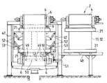
Of the deposition apparatus or film forming equipment 1 not shown in detail for the film forming treatment of the steel strip, FIG. 1 shows a
[0018]
For example, a
[0019]
The
[0020]
The
[0021]
As can be seen from FIG. 2 which is a side view of the apparatus which essentially shows only the inflow slit
[0022]
As can be seen from the equipment composition according to FIG. 4, it is easily possible by being a film-forming tank that allows a cassette-like structure, but five film-forming
[0023]
In the embodiment according to FIG. 5, the
[0024]
In order to disassemble the
[0025]
Furthermore, from Fig. 6-different from the embodiment according to Fig. 3-another embodiment of the device for adjusting the
[0026]
【The invention's effect】
With the configuration according to the present invention as described above, it is possible to configure the deposition apparatus in an extremely compact and easily replaceable manner in a cassette-type structure without requiring a lot of space for equipment. Work is also done without polluting the environment.
[Brief description of the drawings]
FIG. 1 is a longitudinal sectional view of three coating film forming tanks as detailed structures of a film forming facility, in which the vertical wall portions are made of anode plates and provided in parallel with each other, and in this case, these film forming tanks FIG. 2 shows a structural pattern in which two adjacent film-forming tanks surround a deposition chamber, with supply conduit connections leading to their discharge and storage tanks or to a circulation vessel.
FIG. 2 is a side view of a film-forming tank provided in parallel with each other in a cassette-type structure and fixed to each other by a locking member on the end face side.
FIG. 3 is a front view of a film forming tank shown with a closing plate belonging to the left side and the right side and capable of sliding in and out.
FIG. 4 is a side view of a number of film-forming tanks that are placed in the working position of the film-forming equipment and that are equipped with bottom-side support and slide rails for positioning and withdrawing to the side.
FIG. 5 is a front view of details of a film forming tank provided in a splash prevention housing.
FIG. 6 shows a movement mechanism for a sliding plate that can be slid in and out, a movement mechanism for lifting the film formation tank from its built-in position to the extraction level position, and for drawing the film formation tank to the extraction position shown on the right side. It is a front view of the film formation tank shown with this movement mechanism.
FIG. 7 is a detailed view of an anode pair with mutually adjustable anode plates in a steel strip edge with a sliding plate closing plate gap.
[Explanation of symbols]
DESCRIPTION OF SYMBOLS 1
Claims (11)
それぞれの被膜形成槽(2,3)がこれらの被膜形成槽の底部に設けられている支持兼滑りレール(45)により側方へと走出可能であるように構成されていること、および析出室へ電解液を供給するために、供給兼排出導管(28,29)と結合されている転向案内管路(27)が被膜形成槽(2,3)内の頭部側および底部側に設けられていることを特徴とする析出装置。 An apparatus for depositing a metal from an electrolyte containing a metal for coating a steel strip with a metal, the apparatus comprising a film-forming tank provided in parallel with each other, the apparatus Steel strips to be coated within the upper turning roller and / or guide roller are respectively provided vertically relative to one of the coating tanks (2; 3) and the anode plate (11, 11). 12) is guided through the gap between the two outer walls formed as 12) to the lower turning roller and from there to the other upper turning roller and / or guide roller, in each case downward or The steel strip running upwards is acted in the opposite direction to the direction of movement of the steel strip by the electrolyte flow supplied by circulation by the pump, and enters the device. Containing the metal in a manner in which the anode plates (11, 12) adjacent to each other in the coating film formation tanks (2, 3; 3, 2) that are adjacent to each other partition the deposition chamber (13). In an apparatus for depositing a metal from an electrolytic solution,
Each film forming tank (2, 3) is configured to be able to run sideways by a supporting and sliding rail (45) provided at the bottom of these film forming tanks, and a deposition chamber In order to supply the electrolyte solution, turning guide pipes (27) connected to the supply / discharge conduits (28, 29) are provided on the top side and the bottom side in the film forming tank (2, 3). A deposition apparatus characterized by comprising:
Applications Claiming Priority (2)
| Application Number | Priority Date | Filing Date | Title |
|---|---|---|---|
| DE19510667A DE19510667A1 (en) | 1995-03-23 | 1995-03-23 | Separation device for metals from a metal-containing electrolyte |
| DE19510667:9 | 1995-03-23 |
Publications (2)
| Publication Number | Publication Date |
|---|---|
| JPH08269786A JPH08269786A (en) | 1996-10-15 |
| JP3781473B2 true JP3781473B2 (en) | 2006-05-31 |
Family
ID=7757523
Family Applications (1)
| Application Number | Title | Priority Date | Filing Date |
|---|---|---|---|
| JP06317496A Expired - Fee Related JP3781473B2 (en) | 1995-03-23 | 1996-03-19 | Apparatus for depositing metal from an electrolyte containing metal |
Country Status (9)
| Country | Link |
|---|---|
| US (1) | US5718814A (en) |
| EP (1) | EP0733724B2 (en) |
| JP (1) | JP3781473B2 (en) |
| KR (1) | KR100394490B1 (en) |
| CN (1) | CN1152983C (en) |
| AT (1) | ATE168142T1 (en) |
| CA (1) | CA2171378A1 (en) |
| DE (2) | DE19510667A1 (en) |
| TW (1) | TW451002B (en) |
Families Citing this family (2)
| Publication number | Priority date | Publication date | Assignee | Title |
|---|---|---|---|---|
| CN102226289A (en) * | 2011-06-14 | 2011-10-26 | 淮海工学院 | A liquid-phase plasma enhanced nano-composite coating device and its application method |
| CN102409367B (en) * | 2011-12-12 | 2014-04-02 | 云南驰宏锌锗股份有限公司 | Large-area zinc electrolysis anode plate production line |
Family Cites Families (10)
| Publication number | Priority date | Publication date | Assignee | Title |
|---|---|---|---|---|
| US3864235A (en) * | 1971-08-25 | 1975-02-04 | Bobrov S B | Loop electrolyzer |
| US4469564A (en) † | 1982-08-11 | 1984-09-04 | At&T Bell Laboratories | Copper electroplating process |
| US4434040A (en) * | 1982-09-28 | 1984-02-28 | United States Steel Corporation | Vertical-pass electrotreating cell |
| IT1177925B (en) * | 1984-07-24 | 1987-08-26 | Centro Speriment Metallurg | PROCEDURE FOR CONTINUOUS ELECTRODEPOSITION OF METALS WITH HIGH CURRENT DENISTA OF VERTICAL CELLS AND RELEVANT IMPLEMENTATION DEVICE |
| IT1182708B (en) * | 1985-02-08 | 1987-10-05 | Centro Speriment Metallurg | IMPROVEMENT IN VERTICAL CELL DEVICES FOR ELECTRODEPOSITION, IN CONTINUOUS AND HIGH CURRENT DENSITY, OF METALS |
| JPS61190096A (en) * | 1985-02-18 | 1986-08-23 | Nippon Steel Corp | Electroplating installation |
| DE3510592A1 (en) * | 1985-03-23 | 1986-10-02 | Hoesch Stahl AG, 4600 Dortmund | HIGH-SPEED ELECTROLYSIS CELL FOR REFINING BAND-SHAPED GOODS |
| AT394215B (en) * | 1988-11-15 | 1992-02-25 | Andritz Ag Maschf | METHOD FOR ELECTROLYTICALLY PRODUCING A METAL FILM |
| DE3901807A1 (en) * | 1989-01-21 | 1990-07-26 | Roland Schnettler | DEVICE FOR ELECTROLYTICALLY DEPOSITING METALS ON ONE OR BOTH SIDES OF TAPES |
| DE4139066A1 (en) * | 1991-11-28 | 1993-06-03 | Hans Josef May | DEVICE FOR ELECTROLYTIC METAL DEPOSITION ON METAL BANDS |
-
1995
- 1995-03-23 DE DE19510667A patent/DE19510667A1/en not_active Withdrawn
-
1996
- 1996-03-01 TW TW085102475A patent/TW451002B/en not_active IP Right Cessation
- 1996-03-08 CA CA002171378A patent/CA2171378A1/en not_active Abandoned
- 1996-03-13 DE DE59600314T patent/DE59600314D1/en not_active Expired - Fee Related
- 1996-03-13 AT AT96103925T patent/ATE168142T1/en not_active IP Right Cessation
- 1996-03-13 EP EP96103925A patent/EP0733724B2/en not_active Expired - Lifetime
- 1996-03-13 KR KR1019960006631A patent/KR100394490B1/en not_active Expired - Fee Related
- 1996-03-19 JP JP06317496A patent/JP3781473B2/en not_active Expired - Fee Related
- 1996-03-22 CN CNB961073608A patent/CN1152983C/en not_active Expired - Fee Related
- 1996-03-22 US US08/621,780 patent/US5718814A/en not_active Expired - Fee Related
Also Published As
| Publication number | Publication date |
|---|---|
| CN1152983C (en) | 2004-06-09 |
| EP0733724B2 (en) | 2001-07-18 |
| US5718814A (en) | 1998-02-17 |
| KR100394490B1 (en) | 2003-11-17 |
| CN1139710A (en) | 1997-01-08 |
| DE59600314D1 (en) | 1998-08-13 |
| JPH08269786A (en) | 1996-10-15 |
| TW451002B (en) | 2001-08-21 |
| EP0733724A1 (en) | 1996-09-25 |
| ATE168142T1 (en) | 1998-07-15 |
| EP0733724B1 (en) | 1998-07-08 |
| DE19510667A1 (en) | 1996-09-26 |
| CA2171378A1 (en) | 1996-09-24 |
Similar Documents
| Publication | Publication Date | Title |
|---|---|---|
| FI100890B (en) | Apparatus for coating the surface of steel strips with a metal coating | |
| BR112018000773B1 (en) | MULTI WORK BOX SAND MOLD 3D PRINTING DEVICE | |
| CN110027100B (en) | Steam curing device of concrete precast pile | |
| JP3781473B2 (en) | Apparatus for depositing metal from an electrolyte containing metal | |
| KR100749017B1 (en) | Strip casting machine and strip casting machine control method for metal strip manufacturing | |
| CN216785009U (en) | Processing apparatus for processing workpieces | |
| CN217043219U (en) | Processing apparatus for processing workpieces | |
| US5853495A (en) | Process and device for surface treatment of strips with liquids | |
| CN105617725B (en) | Inclined plate sedimentation device and sedimentation basin | |
| CN211645343U (en) | Steel wire quenching cooling device | |
| CN211808477U (en) | Color printing equipment capable of improving ink jet uniformity | |
| CN223907460U (en) | A water distribution outlet algae blocking device | |
| US3468783A (en) | Electroplating apparatus | |
| US4118302A (en) | Cathode structure for use in electrolytic process | |
| CN213623617U (en) | Die cavity cleaning wastewater treatment equipment | |
| CN218361352U (en) | Line rod production is with water cooling spray set | |
| HUT57289A (en) | Horizontal electrolytic metal-coating bath with solving anodes, for electrolytic treating one or both side of steal strips with continuous method, and process for this treating | |
| CN210706510U (en) | Anilox roller belt cleaning device | |
| CN219615036U (en) | Calcium carbonate production waste water recycling system | |
| CN220904417U (en) | Printing ink basin of intaglio printing press | |
| CN212834512U (en) | Water washing printing and dyeing box with air supply type water removing device | |
| CN114322555B (en) | A tin concentrate recyclable smelting system and processing technology thereof | |
| EP0908213B1 (en) | Static filtration plant for liquids | |
| CN113756024B (en) | Novel impregnation production line | |
| CN113882100B (en) | Guide mechanism for dye vat |
Legal Events
| Date | Code | Title | Description |
|---|---|---|---|
| A977 | Report on retrieval |
Free format text: JAPANESE INTERMEDIATE CODE: A971007 Effective date: 20050201 |
|
| A131 | Notification of reasons for refusal |
Free format text: JAPANESE INTERMEDIATE CODE: A131 Effective date: 20050301 |
|
| A601 | Written request for extension of time |
Free format text: JAPANESE INTERMEDIATE CODE: A601 Effective date: 20050531 |
|
| A602 | Written permission of extension of time |
Free format text: JAPANESE INTERMEDIATE CODE: A602 Effective date: 20050606 |
|
| A521 | Request for written amendment filed |
Free format text: JAPANESE INTERMEDIATE CODE: A523 Effective date: 20050624 |
|
| A131 | Notification of reasons for refusal |
Free format text: JAPANESE INTERMEDIATE CODE: A131 Effective date: 20050726 |
|
| A521 | Request for written amendment filed |
Free format text: JAPANESE INTERMEDIATE CODE: A523 Effective date: 20050929 |
|
| A131 | Notification of reasons for refusal |
Free format text: JAPANESE INTERMEDIATE CODE: A131 Effective date: 20060104 |
|
| A521 | Request for written amendment filed |
Free format text: JAPANESE INTERMEDIATE CODE: A523 Effective date: 20060113 |
|
| TRDD | Decision of grant or rejection written | ||
| A01 | Written decision to grant a patent or to grant a registration (utility model) |
Free format text: JAPANESE INTERMEDIATE CODE: A01 Effective date: 20060221 |
|
| A61 | First payment of annual fees (during grant procedure) |
Free format text: JAPANESE INTERMEDIATE CODE: A61 Effective date: 20060307 |
|
| R150 | Certificate of patent or registration of utility model |
Free format text: JAPANESE INTERMEDIATE CODE: R150 |
|
| LAPS | Cancellation because of no payment of annual fees |