JP3781401B2 - Reducing agent for exhaust gas purification catalyst - Google Patents
Reducing agent for exhaust gas purification catalyst Download PDFInfo
- Publication number
- JP3781401B2 JP3781401B2 JP01648399A JP1648399A JP3781401B2 JP 3781401 B2 JP3781401 B2 JP 3781401B2 JP 01648399 A JP01648399 A JP 01648399A JP 1648399 A JP1648399 A JP 1648399A JP 3781401 B2 JP3781401 B2 JP 3781401B2
- Authority
- JP
- Japan
- Prior art keywords
- catalyst
- alcohol
- reducing agent
- exhaust gas
- nox reduction
- Prior art date
- Legal status (The legal status is an assumption and is not a legal conclusion. Google has not performed a legal analysis and makes no representation as to the accuracy of the status listed.)
- Expired - Fee Related
Links
Images
Classifications
-
- F—MECHANICAL ENGINEERING; LIGHTING; HEATING; WEAPONS; BLASTING
- F01—MACHINES OR ENGINES IN GENERAL; ENGINE PLANTS IN GENERAL; STEAM ENGINES
- F01N—GAS-FLOW SILENCERS OR EXHAUST APPARATUS FOR MACHINES OR ENGINES IN GENERAL; GAS-FLOW SILENCERS OR EXHAUST APPARATUS FOR INTERNAL COMBUSTION ENGINES
- F01N3/00—Exhaust or silencing apparatus having means for purifying, rendering innocuous, or otherwise treating exhaust
- F01N3/08—Exhaust or silencing apparatus having means for purifying, rendering innocuous, or otherwise treating exhaust for rendering innocuous
- F01N3/10—Exhaust or silencing apparatus having means for purifying, rendering innocuous, or otherwise treating exhaust for rendering innocuous by thermal or catalytic conversion of noxious components of exhaust
- F01N3/18—Exhaust or silencing apparatus having means for purifying, rendering innocuous, or otherwise treating exhaust for rendering innocuous by thermal or catalytic conversion of noxious components of exhaust characterised by methods of operation; Control
- F01N3/20—Exhaust or silencing apparatus having means for purifying, rendering innocuous, or otherwise treating exhaust for rendering innocuous by thermal or catalytic conversion of noxious components of exhaust characterised by methods of operation; Control specially adapted for catalytic conversion ; Methods of operation or control of catalytic converters
- F01N3/206—Adding periodically or continuously substances to exhaust gases for promoting purification, e.g. catalytic material in liquid form, NOx reducing agents
-
- F—MECHANICAL ENGINEERING; LIGHTING; HEATING; WEAPONS; BLASTING
- F01—MACHINES OR ENGINES IN GENERAL; ENGINE PLANTS IN GENERAL; STEAM ENGINES
- F01N—GAS-FLOW SILENCERS OR EXHAUST APPARATUS FOR MACHINES OR ENGINES IN GENERAL; GAS-FLOW SILENCERS OR EXHAUST APPARATUS FOR INTERNAL COMBUSTION ENGINES
- F01N2610/00—Adding substances to exhaust gases
- F01N2610/02—Adding substances to exhaust gases the substance being ammonia or urea
Landscapes
- Chemical & Material Sciences (AREA)
- Engineering & Computer Science (AREA)
- Chemical Kinetics & Catalysis (AREA)
- Health & Medical Sciences (AREA)
- Toxicology (AREA)
- Combustion & Propulsion (AREA)
- Mechanical Engineering (AREA)
- General Engineering & Computer Science (AREA)
- Exhaust Gas After Treatment (AREA)
- Exhaust Gas Treatment By Means Of Catalyst (AREA)
- Catalysts (AREA)
Description
【0001】
【産業上の利用分野】
本発明は、内燃機関の排ガス中のNOxを触媒により選択還元する際に処理前の排ガス中に導入される還元剤及びその還元剤を用いて排ガス中のNOxを低減する方法に関する。
【0002】
【従来の技術】
内燃機関、例えばディーゼルエンジンにおいて燃焼温度が高い場合にNOxが発生し易いことは良く知られており、そのような場合排ガス中に含まれるNOxを選択的に還元する触媒を用いて排ガスを浄化することが行なわれている。排ガス中にはそのような還元処理のために還元剤として有効に作用する物質の量が希少であるので、NOx還元の促進のために処理前の排ガス中に必要に応じて外部から何らかの還元剤を導入することが行なわれる。この目的のための還元剤としては炭化水素類(例えば軽油)が一般的であるが、尿素がNOx還元剤として注目されてきている。従来排ガス中に尿素を均一に分布させるために尿素を水溶液の形で排気管中のNOx還元触媒の上流側のところで噴射して使用してきた。
【0003】
しかしながら、尿素を溶解するための水自体は排ガス中のNOx還元条件下で還元剤として作用しうるものではなくそのまま大気中へ放出されるから、NOx還元処理反応への実体的あるいは直接的寄与はなく車載重量を徒らに大きくしている。
【0004】
さらには水の凍結点は0℃であり、冬期あるいは寒冷地において尿素水溶液をNOx還元剤で使用するとすれば、凍結する問題があり、その凍結防止のための加温、保温装置手段を設けると、コスト増加、スペース及び重量の増加という好ましくない問題を引き起こす。
【0005】
【発明が解決しようとする課題】
本発明者等は、上記のような従来のNOx還元用尿素還元剤の使用に伴なう諸問題に鑑み、それらを解決、解消すべく研究検討を重ね、さらにはより効率的なNOx低減方法を創出すべく研究を実施して本発明の還元剤及びNOx低減方法を案出した。本発明はアルコール類が比重が小さく(軽量性)、尿素の溶剤として充分な溶解性を示し、かつ排ガス中のNOx用還元剤として機能しうるという知見に基いており、また尿素のアルコール溶液からなるNOx用還元剤を低温から高温までの広い温度範囲にわたって効率的に機能させるための触媒の組み合せの発見にも基いている。
【0006】
【課題を解決するための手段】
本発明は、排ガス中のNOxを触媒により選択還元処理する際に処理前の排ガス中に導入される還元剤であって、尿素のアルコール溶液からなることを特徴とする上記還元剤を提供する。
【0007】
さらに本発明は上記本発明の還元剤を導入した排ガスを最初に尿素によるNOx還元用触媒、次いでアルコールによるNOx還元用触媒と連続的に接触させることからなる排ガス中のNOx低減方法をも提供する。この本発明方法における第2番目の触媒、すなわちアルコールによるNOx還元用触媒から流出する排ガス流中には尿素由来のアンモニアあるいはその誘導体や残留アルコール等が微量存在することもありうるので、そのような第2番目の触媒から流出する排ガス流を、アンモニア及びアルコールを酸化させるための酸化触媒と接触させることも本発明の範囲内である。
【0008】
本発明の還元剤(組成物)を調製するために用いられるアルコール(例えばC1〜C7アルコール、好ましくはC1〜C3アルコール)は低比重であり、また低い凍結点(融点)を有する。本発明のために好ましいアルコールの例であるメタノール、エタノール及びイソプロピルアルコールは、概略の比重が0.80;0.79及び0.786g/ml(20℃)であり、水よりも約20%またはそれ以上軽い。
【0009】
これら3種のアルコールの融点はそれぞれ−94℃;−114℃;及び−90℃であり、使用中に凍結することはない。これらのアルコールは一般に尿素に対して良溶媒であり、尿素を高濃度で溶解させることができる。さらにアルコールは尿素と比較して相対的に低い温度域でNOx還元剤として作用するので、本発明の尿素のアルコール溶液からなる還元剤は、尿素単独水溶液からなる還元剤と対比してほぼ200℃からほぼ450℃の広温度範囲で高いNOx還元作用を果す(実施例参照)。
【0010】
そのような高効率のNOx還元を達成するには、本発明の還元剤をなす成分である尿素及びアルコールのそれぞれの還元作用を誘起するために別々の触媒組成
(構成)を採用すること、ならびにそれらの触媒の排気管系での配置順序を選定することが重要である。かくして本発明では、多様な実験の結果、相対的に高温でNOx還元活性を発現する尿素によるNOx還元用触媒を排気管内で上流側に配置し、そして相対的に低温でNOx還元活性を発現するアルコールによるNOx還元用触媒をその下流側に配置する分離直列配置方式を選択する。
【0011】
本発明における尿素によるNOx還元用触媒は銅イオンでイオン交換されたゼオライトが好ましく、最も好ましくは銅イオン交換ZSM−5であり、実装触媒は、銅イオン交換ゼオライト触媒粉末をバインダー含有スラリーとし、このスラリーで耐火性(例:コージェライト製)ハニカムモノリスをディップコートし、乾燥、焼成することによる公知方法で作成される。
【0012】
本発明におけるアルコールによるNOx還元用触媒は、γ−アルミナ、または銀を担持したアルミナからなるのが好ましい。この触媒も実装されるときには上記と同様に耐火性ハニカムモノリスにディップコートされた形で使用される。
【0013】
上記の尿素によるNOx還元用触媒及びアルコールによるNOx還元用触媒を経て流出するNOx低減処理の済んだ排ガス中には尿素由来のアンモニアや余剰のアルコール等を場合により微量含むことがあるので、そのアルコールによるNOx還元用触媒の下流側の排気管内にそのようなアンモニア及びアルコールを酸化処理して浄化するための酸化触媒(例えばPt、Pd、Ag、Cu、Fe及びそれらの酸化物のうちの少なくとも一つを担持したアルミナ)を配置して、排ガスをさらに処理するのが好ましい。この酸化触媒も前のようなハニカムにディップコートされた形で排気管内に実装される。
【0014】
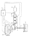
本発明の実施態様例を図1の概念図を参照して説明する。エンジン1からの排気ガスはマニホールドを経て排気管Aに入る。排気管Aの途中には直径を拡大した膨張部分Bが設けられ、ここに上流側から順次に尿素によるNOx還元用触媒被覆ハニカム6、アルコールによるNOx還元用触媒被覆ハニカム7及び(任意に、そして好ましくは)アンモニア及びアルコール酸化用触媒8が直列に収容されている。この触媒収容膨張部分Bの下流側にはマフラ9が続き、排ガスはこれを経て最終的に放出される。
【0015】
本発明による尿素−アルコール還元剤はタンク3内に貯蔵され、そのタンクからパイプがポンプ3及び電磁弁4を経て触媒収容膨張部分Bの上流側のところの排気管壁を貫通し、排気管内中央部まで延在し、その先端部に触媒収容膨張部分Bに向けた還元剤噴射ノズル5が設けられている。
【0016】
エンジン1には回転数センサ10及び負荷センサ11が、マニホールドから還元剤噴射ノズル5に至るまでの排気管中にNOxセンサ12aが、還元剤噴射ノズル5よりも下流で、尿素−NOx還元用触媒被覆ハニカム6の入口付近に排気温センサ13が、そしてアンモニア−アルコール酸化用触媒8とマフラ9との間にNOxセンサ12bが、それぞれ付設され、それらのセンサの検出データ信号は電子制御装置(ECU)Cへ入力され、所定のマップ上で還元剤導入の必要性が認識されると、ECUからポンプ3及び電磁弁4(開)の作動信号が出され、尿素−アルコール還元剤がノズル5から排ガス流内へ噴射され、還元剤担持排ガスはNOx還元用触媒列で効率よく処理される。ECUのマップ上で還元剤導入の必要性が認識されないときにはECUから作動停止信号がポンプ3及び電磁弁4(閉)に送られ、還元剤の噴射は行なわれない。
【0017】
【実施例】
図1に概略示した装置を用いて、本発明による還元剤(メチルアルコール中に60重量%の尿素を溶解した溶液)及び従来の尿素水溶液(尿素濃度60重量%)の排ガスNOx低減性能の比較試験を行なった。ただしアンモニア・アルコール酸化触媒被覆ハニカム8は使用しなかった。
【0018】
(a) 尿素によるNOx還元用触媒の調製
硝酸銅(3.6g)を水(100ml)に溶解した溶液にZSM−5ゼオライト(SiO2/Al2O3=30;20g)を浸漬し、約60℃に維持しながら2日間にわたって撹拌を続け、ZSM−5ゼオライトのイオン交換基を銅イオンで置換させた。この混合液を濾過し、脱イオン水で充分に洗浄し、固液分離して得られたゼオライトケーキを乾燥し(約100℃×2時間)、しかる後、大気中500℃で5時間焼成し、粉砕して150〜100メッシュの粉体とした。この銅イオン交換ZSM−5粉末70重量部、バインダーとしてのアルミナゾル20重量部及び水100重量部を高速ミキサーで撹拌し、均質スラリーとした。コージェライト製円筒ハニカム(セル数400cpi)を上記スラリーに浸漬し、引き上げ、余剰付着スラリーを空気ジェットで吹き払い、乾燥し、ハニカム上に層厚50〜100ミクロンの触媒被覆を生成させた。このハニカムを図1における6として装填した。
【0019】
(b) アルコールによるNOx還元用触媒の調製
γ−アルミナ粉末70重量部、バインダーとしてのアルミナゾル20重量部及び水100重量部を用いて上記(a)の操作(ディップコート法)と同様にして触媒被覆ハニカムを作り、これを図1における7として装填した。
【0020】
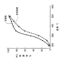
ディーゼルエンジンを1〜13モードで運転し、種々の排気温度におけるNOx低減率を上記2種の還元剤について繰り返し測定し、表1の平均値を得た。

【図面の簡単な説明】
【図1】本発明の一実施態様例の概念図。
【図2】尿素のアルコール溶液からなる還元剤(本発明)と尿素水溶液からなる還元剤(従来技術)とを用いた場合の種々の温度におけるNOx低減率の対比グラフ。
【符号の説明】
1 エンジン
2 尿素−アルコール溶液還元剤タンク
3 ポンプ
4 電磁弁
5 噴射ノズル
6 尿素NOx還元用触媒被覆ハニカム
7 アルコールNOx還元用触媒被覆ハニカム
8 アンモニア・アルコール酸化触媒被覆ハニカム
9 マフラ
10 回転数センサ
11 負荷センサ
12a NOxセンサ
12b NOxセンサ
13 排気温センサ
A 排気管
B 触媒収容膨張部分
C 電子制御装置(ECU)[0001]
[Industrial application fields]
The present invention relates to a reducing agent introduced into exhaust gas before treatment when NOx in exhaust gas of an internal combustion engine is selectively reduced by a catalyst, and a method for reducing NOx in exhaust gas using the reducing agent.
[0002]
[Prior art]
It is well known that NOx is easily generated when the combustion temperature is high in an internal combustion engine, for example, a diesel engine. In such a case, exhaust gas is purified using a catalyst that selectively reduces NOx contained in the exhaust gas. Has been done. Since the amount of a substance that effectively acts as a reducing agent for such reduction treatment is scarce in the exhaust gas, any reducing agent is required from the outside as needed in the exhaust gas before treatment to promote NOx reduction. Is carried out. Hydrocarbons (eg, light oil) are common as reducing agents for this purpose, but urea has been attracting attention as a NOx reducing agent. Conventionally, urea has been used by being injected in the form of an aqueous solution at the upstream side of the NOx reduction catalyst in the exhaust pipe in order to uniformly distribute urea in the exhaust gas.
[0003]
However, since water for dissolving urea itself does not act as a reducing agent under the NOx reduction conditions in exhaust gas and is released into the atmosphere as it is, the substantial or direct contribution to the NOx reduction treatment reaction is Without increasing the weight on the vehicle.
[0004]
Further, the freezing point of water is 0 ° C., and if an aqueous urea solution is used as a NOx reducing agent in winter or cold regions, there is a problem of freezing. If a heating and heat retaining device means for preventing the freezing is provided, Cause undesirable problems of increased cost, space and weight.
[0005]
[Problems to be solved by the invention]
In view of the problems associated with the use of the conventional NOx reducing urea reducing agent as described above, the present inventors have conducted research and studies to solve and solve them, and more efficiently reduce NOx. Research was conducted to create a reducing agent and NOx reduction method of the present invention. The present invention is based on the knowledge that alcohol has a small specific gravity (light weight), exhibits sufficient solubility as a solvent for urea, and can function as a reducing agent for NOx in exhaust gas. This is also based on the discovery of a combination of catalysts for efficiently functioning the reducing agent for NOx over a wide temperature range from low temperature to high temperature.
[0006]
[Means for Solving the Problems]
The present invention provides the above reducing agent, which is a reducing agent that is introduced into the exhaust gas before the treatment when NOx in the exhaust gas is selectively reduced with a catalyst, and is made of an alcohol solution of urea.
[0007]
Furthermore, the present invention also provides a method for reducing NOx in exhaust gas, which comprises continuously contacting the exhaust gas into which the reducing agent of the present invention has been introduced first with a catalyst for NOx reduction with urea and then with a catalyst for NOx reduction with alcohol. . In the exhaust gas stream flowing out from the second catalyst in the method of the present invention, that is, the catalyst for NOx reduction by alcohol, there may be a trace amount of urea-derived ammonia or its derivative, residual alcohol, etc. It is also within the scope of the present invention to contact the exhaust gas stream flowing out of the second catalyst with an oxidation catalyst for oxidizing ammonia and alcohol.
[0008]
The alcohol used to prepare the reducing agent of the present invention (composition) (e.g. C 1 -C 7 alcohols, preferably C 1 -C 3 alcohol) has a low specific gravity and low freezing point (melting point) . Examples of preferred alcohols for the present invention, methanol, ethanol and isopropyl alcohol, have an approximate specific gravity of 0.80; 0.79 and 0.786 g / ml (20 ° C.) and about 20% or less than water. It is lighter than that.
[0009]
These three alcohols have melting points of −94 ° C., −114 ° C., and −90 ° C., respectively, and do not freeze during use. These alcohols are generally good solvents for urea and can dissolve urea at a high concentration. Furthermore, since alcohol acts as a NOx reducing agent in a relatively low temperature range compared to urea, the reducing agent comprising the urea alcohol solution of the present invention is approximately 200 ° C. in comparison with the reducing agent comprising the urea aqueous solution alone. To a high NOx reducing action over a wide temperature range of approximately 450 ° C. (see Examples).
[0010]
In order to achieve such highly efficient NOx reduction, adopting separate catalyst compositions (configurations) to induce the respective reducing actions of urea and alcohol, which are the components of the reducing agent of the present invention, and It is important to select the order of arrangement of these catalysts in the exhaust pipe system. Thus, in the present invention, as a result of various experiments, a NOx reduction catalyst by urea that expresses NOx reduction activity at a relatively high temperature is arranged upstream in the exhaust pipe, and the NOx reduction activity is expressed at a relatively low temperature. A separation serial arrangement method is selected in which a catalyst for NOx reduction with alcohol is arranged downstream thereof.
[0011]
The NOx reduction catalyst with urea in the present invention is preferably a zeolite ion-exchanged with copper ions, most preferably copper ion-exchanged ZSM-5, and the mounting catalyst is a copper-ion exchanged zeolite catalyst powder as a binder-containing slurry. It is prepared by a known method by dip-coating a fire-resistant (eg, cordierite) honeycomb monolith with slurry, drying, and firing.
[0012]
The catalyst for reducing NOx with alcohol in the present invention is preferably composed of γ-alumina or alumina supporting silver. When this catalyst is also mounted, it is used in a dip-coated form on a refractory honeycomb monolith as described above.
[0013]
The exhaust gas that has been subjected to the NOx reduction treatment that flows out through the NOx reduction catalyst using urea and the NOx reduction catalyst using alcohol may contain a small amount of urea-derived ammonia, excess alcohol, or the like. An oxidation catalyst (for example, Pt, Pd, Ag, Cu, Fe and at least one of those oxides) for oxidizing and purifying ammonia and alcohol in the exhaust pipe downstream of the NOx reduction catalyst by It is preferable to further treat the exhaust gas by placing an alumina). This oxidation catalyst is also mounted in the exhaust pipe in the form of dip coating on the honeycomb as before.
[0014]
An embodiment of the present invention will be described with reference to the conceptual diagram of FIG. Exhaust gas from the
[0015]
The urea-alcohol reducing agent according to the present invention is stored in the tank 3, and the pipe from the tank passes through the exhaust pipe wall upstream of the catalyst containing expansion part B via the pump 3 and the electromagnetic valve 4, and the center in the exhaust pipe. The reducing agent injection nozzle 5 is provided at the front end portion of the catalyst containing expansion portion B.
[0016]
The
[0017]
【Example】
Comparison of exhaust gas NOx reduction performance of a reducing agent according to the present invention (a solution of 60% by weight of urea dissolved in methyl alcohol) and a conventional aqueous urea solution (urea concentration of 60% by weight) using the apparatus schematically shown in FIG. A test was conducted. However, the ammonia / alcohol oxidation catalyst-coated
[0018]
(A) Preparation of catalyst for NOx reduction with urea ZSM-5 zeolite (SiO 2 / Al 2 O 3 = 30; 20 g) was immersed in a solution of copper nitrate (3.6 g) dissolved in water (100 ml). Stirring was continued for 2 days while maintaining the temperature at 60 ° C. to replace the ion exchange groups of the ZSM-5 zeolite with copper ions. This mixed solution is filtered, washed thoroughly with deionized water, and the zeolite cake obtained by solid-liquid separation is dried (about 100 ° C. × 2 hours), and then calcined at 500 ° C. in the atmosphere for 5 hours. The powder was pulverized to a powder of 150 to 100 mesh. 70 parts by weight of this copper ion exchanged ZSM-5 powder, 20 parts by weight of alumina sol as a binder and 100 parts by weight of water were stirred with a high-speed mixer to obtain a homogeneous slurry. A cordierite cylindrical honeycomb (
[0019]
(B) Preparation of NOx reduction catalyst with alcohol Catalyst using 70 parts by weight of γ-alumina powder, 20 parts by weight of alumina sol as a binder and 100 parts by weight of water in the same manner as in the above operation (a dip coating method). A coated honeycomb was made and loaded as 7 in FIG.
[0020]
The diesel engine was operated in the 1-13 mode, and the NOx reduction rate at various exhaust temperatures was repeatedly measured for the above two kinds of reducing agents, and the average values in Table 1 were obtained.
[Brief description of the drawings]
FIG. 1 is a conceptual diagram of an embodiment of the present invention.
FIG. 2 is a graph comparing NOx reduction rates at various temperatures when using a reducing agent composed of an alcohol solution of urea (the present invention) and a reducing agent composed of an aqueous urea solution (prior art).
[Explanation of symbols]
DESCRIPTION OF
Claims (4)
尿素のアルコール溶液からなり、該アルコールがメタノール、エタノール、イソプロピルアルコールに代表される炭素数が7までのアルコールまたはそれらの混合物である還元剤を排ガス中に導入し、A reducing agent comprising an alcohol solution of urea, the alcohol being an alcohol having a carbon number up to 7 typified by methanol, ethanol, isopropyl alcohol or a mixture thereof, into the exhaust gas;
該排ガスを、最初に尿素によるNOx還元用触媒、次いでアルコールによるNOx還元用触媒と連続的に接触させることからなる、前記方法。Said process comprising continuously contacting said exhaust gas first with a catalyst for NOx reduction with urea and then with a catalyst for NOx reduction with alcohol.
Priority Applications (1)
| Application Number | Priority Date | Filing Date | Title |
|---|---|---|---|
| JP01648399A JP3781401B2 (en) | 1999-01-26 | 1999-01-26 | Reducing agent for exhaust gas purification catalyst |
Applications Claiming Priority (1)
| Application Number | Priority Date | Filing Date | Title |
|---|---|---|---|
| JP01648399A JP3781401B2 (en) | 1999-01-26 | 1999-01-26 | Reducing agent for exhaust gas purification catalyst |
Publications (2)
| Publication Number | Publication Date |
|---|---|
| JP2000213335A JP2000213335A (en) | 2000-08-02 |
| JP3781401B2 true JP3781401B2 (en) | 2006-05-31 |
Family
ID=11917544
Family Applications (1)
| Application Number | Title | Priority Date | Filing Date |
|---|---|---|---|
| JP01648399A Expired - Fee Related JP3781401B2 (en) | 1999-01-26 | 1999-01-26 | Reducing agent for exhaust gas purification catalyst |
Country Status (1)
| Country | Link |
|---|---|
| JP (1) | JP3781401B2 (en) |
Families Citing this family (7)
| Publication number | Priority date | Publication date | Assignee | Title |
|---|---|---|---|---|
| US7229597B2 (en) | 2003-08-05 | 2007-06-12 | Basfd Catalysts Llc | Catalyzed SCR filter and emission treatment system |
| JP4267534B2 (en) * | 2004-07-23 | 2009-05-27 | 日野自動車株式会社 | Abnormality detection method for exhaust purification system |
| JP2006057578A (en) * | 2004-08-23 | 2006-03-02 | Hino Motors Ltd | Exhaust emission control device |
| US7585490B2 (en) | 2005-04-15 | 2009-09-08 | University Of Iowa Research Foundation | Synthesis and use of nanocrystalline zeolites |
| JP2009035644A (en) | 2007-08-02 | 2009-02-19 | Denso Corp | Antifreeze urea solution for urea selective catalytic reduction (scr) system and urea scr system |
| PL2918330T3 (en) * | 2008-05-07 | 2017-07-31 | Umicore Ag & Co. Kg | Method for reducing nitrogen oxides in hydrocarbon-containing waste gas streams using a scr catalytic converter comprising a molecular sieve |
| GB2485530A (en) * | 2010-11-11 | 2012-05-23 | Johnson Matthey Plc | Catalyst system |
-
1999
- 1999-01-26 JP JP01648399A patent/JP3781401B2/en not_active Expired - Fee Related
Also Published As
| Publication number | Publication date |
|---|---|
| JP2000213335A (en) | 2000-08-02 |
Similar Documents
| Publication | Publication Date | Title |
|---|---|---|
| JP5854995B2 (en) | Gasoline engine exhaust gas treatment system | |
| CN103269773B (en) | For the NO strengthened 2the structural formula diesel oxidation catalyst of generator | |
| JP3440290B2 (en) | Exhaust gas purification method | |
| RU2618058C2 (en) | Catalyzed block carrier | |
| JP6606544B2 (en) | Exhaust system with modified drain NOx trap | |
| CN101410597B (en) | Method of purifying exhaust gas from internal combustion engine | |
| KR20180125168A (en) | Electric elements in exhaust for NOx storage catalysts and SCR systems | |
| EP2113296A2 (en) | Exhaust gas purification method using selective reduction catalyst | |
| JP6794552B2 (en) | Diesel engine exhaust gas purification catalyst | |
| WO2013172128A1 (en) | Exhaust gas purifier | |
| CN107002533B (en) | Exhaust gas aftertreatment device for combustion engine | |
| WO2018025827A1 (en) | Cold start-compatible urea scr system | |
| CN108348855A (en) | Catalytic filter with cigarette ash catalyst and SCR catalyst | |
| BRPI0908461B1 (en) | SUITABLE EMISSION TREATMENT SYSTEM FOR THE TREATMENT OF A DISCHARGE SYSTEM DOWNWARD OF A DIRECT INJECTION GASOLINE ENGINE | |
| JPH11166410A (en) | Exhaust emission control device | |
| CN105683518B (en) | With modified lean combustion NOxThe exhaust system and method for trap | |
| GB2517035A (en) | Catalyzed filter for treating exhaust gas | |
| KR20190132669A (en) | NOx Adsorbent Catalyst | |
| KR20190132674A (en) | NOx Adsorbent Catalyst | |
| JP3781401B2 (en) | Reducing agent for exhaust gas purification catalyst | |
| JP3830566B2 (en) | Exhaust gas purification system | |
| JPH10118454A (en) | Apparatus for purifying exhaust gas | |
| CN112727567B (en) | Particulate filter for diesel engine and application of particulate filter in integrated reduction of NOx and soot emission in cold start stage of diesel engine | |
| JPH06142523A (en) | Waste gas purifying material and waste gas purifying method | |
| WO2022216658A1 (en) | Exhaust treatment method and apparatus having particulate filters and scr |
Legal Events
| Date | Code | Title | Description |
|---|---|---|---|
| A977 | Report on retrieval |
Free format text: JAPANESE INTERMEDIATE CODE: A971007 Effective date: 20050826 |
|
| A131 | Notification of reasons for refusal |
Free format text: JAPANESE INTERMEDIATE CODE: A131 Effective date: 20051201 |
|
| A521 | Written amendment |
Free format text: JAPANESE INTERMEDIATE CODE: A523 Effective date: 20060130 |
|
| TRDD | Decision of grant or rejection written | ||
| A01 | Written decision to grant a patent or to grant a registration (utility model) |
Free format text: JAPANESE INTERMEDIATE CODE: A01 Effective date: 20060302 |
|
| A61 | First payment of annual fees (during grant procedure) |
Free format text: JAPANESE INTERMEDIATE CODE: A61 Effective date: 20060306 |
|
| R150 | Certificate of patent or registration of utility model |
Free format text: JAPANESE INTERMEDIATE CODE: R150 |
|
| FPAY | Renewal fee payment (event date is renewal date of database) |
Free format text: PAYMENT UNTIL: 20090317 Year of fee payment: 3 |
|
| FPAY | Renewal fee payment (event date is renewal date of database) |
Free format text: PAYMENT UNTIL: 20100317 Year of fee payment: 4 |
|
| FPAY | Renewal fee payment (event date is renewal date of database) |
Free format text: PAYMENT UNTIL: 20110317 Year of fee payment: 5 |
|
| FPAY | Renewal fee payment (event date is renewal date of database) |
Free format text: PAYMENT UNTIL: 20110317 Year of fee payment: 5 |
|
| FPAY | Renewal fee payment (event date is renewal date of database) |
Free format text: PAYMENT UNTIL: 20120317 Year of fee payment: 6 |
|
| FPAY | Renewal fee payment (event date is renewal date of database) |
Free format text: PAYMENT UNTIL: 20130317 Year of fee payment: 7 |
|
| FPAY | Renewal fee payment (event date is renewal date of database) |
Free format text: PAYMENT UNTIL: 20130317 Year of fee payment: 7 |
|
| FPAY | Renewal fee payment (event date is renewal date of database) |
Free format text: PAYMENT UNTIL: 20140317 Year of fee payment: 8 |
|
| LAPS | Cancellation because of no payment of annual fees |