JP3780098B2 - Internal combustion engine, internal combustion engine ignition plug, internal combustion engine cylinder head, and internal combustion engine ignition plug manufacturing method - Google Patents
Internal combustion engine, internal combustion engine ignition plug, internal combustion engine cylinder head, and internal combustion engine ignition plug manufacturing method Download PDFInfo
- Publication number
- JP3780098B2 JP3780098B2 JP12441898A JP12441898A JP3780098B2 JP 3780098 B2 JP3780098 B2 JP 3780098B2 JP 12441898 A JP12441898 A JP 12441898A JP 12441898 A JP12441898 A JP 12441898A JP 3780098 B2 JP3780098 B2 JP 3780098B2
- Authority
- JP
- Japan
- Prior art keywords
- plug
- internal combustion
- combustion engine
- cylinder head
- tip
- Prior art date
- Legal status (The legal status is an assumption and is not a legal conclusion. Google has not performed a legal analysis and makes no representation as to the accuracy of the status listed.)
- Expired - Lifetime
Links
Images


Classifications
-
- Y—GENERAL TAGGING OF NEW TECHNOLOGICAL DEVELOPMENTS; GENERAL TAGGING OF CROSS-SECTIONAL TECHNOLOGIES SPANNING OVER SEVERAL SECTIONS OF THE IPC; TECHNICAL SUBJECTS COVERED BY FORMER USPC CROSS-REFERENCE ART COLLECTIONS [XRACs] AND DIGESTS
- Y02—TECHNOLOGIES OR APPLICATIONS FOR MITIGATION OR ADAPTATION AGAINST CLIMATE CHANGE
- Y02T—CLIMATE CHANGE MITIGATION TECHNOLOGIES RELATED TO TRANSPORTATION
- Y02T10/00—Road transport of goods or passengers
- Y02T10/10—Internal combustion engine [ICE] based vehicles
- Y02T10/12—Improving ICE efficiencies
Landscapes
- Ignition Installations For Internal Combustion Engines (AREA)
- Combustion Methods Of Internal-Combustion Engines (AREA)
- Cylinder Crankcases Of Internal Combustion Engines (AREA)
- Gasket Seals (AREA)
- Spark Plugs (AREA)
Description
【0001】
【発明の属する技術分野】
本発明は、内燃機関、これに用いる点火プラグ、シリンダーヘッド、および内燃機関用点火プラグの製造方法に関し、さらに詳しくは、燃費の向上が可能な内燃機関、これに用いる点火プラグ、シリンダーヘッド、および内燃機関用点火プラグの製造方法に関する。
【0002】
【従来の技術】
近年、内燃機関、例えば、自動車用エンジン等の燃費向上のため、希薄燃焼(リーンバーン)や、燃料直接噴射(ダイレクトイジェクション)による内燃機関の駆動が行われるようになってきている。このような内燃機関(以下、単にエンジンとも言う)においては、点火プラグ(以下、単にプラグとも言う)の着火性を向上させて、確実に混合気に着火させることが望まれる。
ところで、従来のエンジンにおいては、シリンダーヘッドに形成するプラグ取付孔に形成した雌ネジ、およびプラグの主体金具の取付ネジ部に形成する雄ねじの位相については、特に規定されていない。従って、プラグ取付孔にプラグをネジ込んだ場合に、シリンダー内に露出する取付ネジ部の先端部に固着された外側電極の周方向位置は、定まらない。つまり、シリンダーヘッドとプラグとの組み合わせにより、外側電極の周方向位置は、360度の範囲でいずれの位置にもなり得るようにされていた。
【0003】
【発明が解決しようとする課題】
しかし、上記したように、リーンバーンや燃料直接噴射による駆動の場合には、着火可能な濃い(燃料比率の高い)混合気の流れ(スワール)が形成され、プラグの中心電極と外側電極との間の放電領域を、そのスワールが通るように設計されるため、外側電極の固着位置がスワールの上流側にあると、濃い混合気が放電領域に流れ込みにくくなり、失火となりやすい。従って、この場合には、A/F(Air/Fuel)値が比較的小さい範囲でしか、エンジンが駆動できず、燃費が低下する。
【0004】
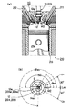
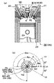
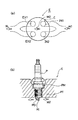
例えば、図22(a)に示すような4バルブエンジンEにおいて、以下のような試験を行った。このエンジンEにおいて、図中右側の2つのバルブIN1,2を吸気(インテーク)側とし、左側2つのバルブEX1,2を排気(エグゾースト)側とする。このとき、図中右側にから供給された矢印で示す混合気M1は、バルブIN1,2からシリンダーC内に導かれて、図中中央を矢印M2で示す左向きのスワールとなって流れ、着火後、バルブEX1,2を通じて矢印で示す排気Nとなって排出される。なお、図22(a)においてはプラグPの記載は省略した。ただし、シリンダーCの中央に記した×印が、点火プラグPの放電領域である。これを、エンジンEの横方向から見ると、図22(b)に示すようであり、スワールM2が、シリンダーヘッドCHに取り付けられたプラグPの中心電極PIと外側電極POの間の放電領域を通るようにされている。
【0005】
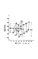
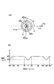
このようなエンジンEを用いて、外側電極POの固着部POaの周方向位置を変えたプラグPを用いて限界A/F値を測定した。まず、1極(外側電極POが1つ)の点火プラグPを用いた場合について説明する。図23(a)に示すようにプラグPの軸方向先端側から見たときに、取付ネジ部先端部PTeの中心Oを通るスワールM2の流線Lmと、取付ネジ部先端部PTeとの交点のうち、上流側の交点Sを基準として、反時計方向に測ったときの取付ネジ部先端部PTeに固着された外側電極POの固着部POaの周方向位置を、角度θ(deg)で示す。
【0006】
すると、図23(b)に示すように、θ=−30〜30の範囲を除けば、限界A/F値はほぼ一定(a1)であったが、θ=−30〜30の範囲では、限界A/F値が低下し、θ=0では、限界A/F値=a2にまで低下する。即ち、この範囲では、比較的リッチな(濃い)混合気でないと作動しないことが判る。これは、外側電極POの固着部POaがスワールM2の上流側にあるために、中心電極PIと外側電極POとの間の放電領域を、スワールM2が通ることが妨げられたためと解される。
従って、あらゆる角度θ、即ち、外側電極POの固着部POaがどの周方向位置の場合であっても、このエンジンEを動作可能とするためには、限界A/F値としてa2の値までしか用いることができないこととなる。
なお、上記限界A/F値の測定方法としては、以下の方法によった。即ち、プラグPを取り付けて角度θを測定しておき、その後、エンジンEを作動させ、徐々に混合気を薄くしてA/F値を上昇させる。すると、プラグPが失火して、エンジンEの回転数が変動し始めるので、その回転数変動が10%となったときのA/F値を限界A/F値とした。これを、プラグPを取り替えることにより、色々な角度θについて測定を行って、図23(b)に示すグラフを得た。
【0007】
同様に、互いに180度異なる位置に固着された2つの外側電極PO1,2を有する2極の点火プラグPを用いた場合について測定した。なお、角度θの決め方は、1極の場合と同様である。即ち、図24(a)に示すようにプラグPの軸方向先端側から見たときに、取付ネジ部先端部PTeの中心Oを通るスワールM2の流線Lmと、取付ネジ部先端部PTeとの交点のうち、上流側の交点Sを基準として、取付ネジ部先端部PTeに固着された外側電極POの固着部POaの周方向位置を角度θ(deg)で示す。
【0008】
すると、図24(b)に示すように、θ=−30〜30およびθ=150〜210(=−150〜−210)の範囲を除けば、限界A/Fの値はほぼ一定(a3)であったが、θ=−30〜30および150〜210の範囲では、限界A/F値が低下し、θ=0および180では、限界A/F値=a4まで低下する。即ち、この範囲では、比較的リッチな(濃い)混合気でないと作動しないことが判る。
従って、あらゆる角度θ、即ち、外側電極PO1,2の固着部PO1a,PO2aがどの周方向位置の場合であっても、このエンジンEを動作可能とするためには、限界A/F値としてa4の値までしか用いることができないこととなる。 ここで、プラグPの外側電極POの位置を所望の位置に調整するため、プラグPの締め付けトルクを調整する方法が考えられるが、プラグの締め付けにおいては、適正な締め付けトルクが定められており(例えば、ISO1919:1988(E) 等)、必ずしも、すべての場合に調整できるとは限らないし、トルク不足や過締め付けの場合には、プラグの機能を果たし得ない場合も生じる。
【0009】
本発明は、上記した問題点に鑑み点されたものであって、薄い混合気(高いA/F値)でも駆動でき、燃費の良い内燃機関、およびそれに適する内燃機関用点火プラグおよびシリンダーヘッドを提供し、さらには、そのような点火プラグの製造方法を提供することを目的とする。
【0010】
【課題を解決するための手段、作用及び効果】
しかしてその解決手段は、テーパ面のプラグ座面を備える径大本体部と、該径大本体部から軸方向に延び、内燃機関用シリンダーヘッドに設けたプラグ取付孔に螺挿するための雄ネジが螺刻された取付ネジ部と、を有する主体金具と、上記取付ネジ部の先端部に固着された1または複数の外側電極と、を備える内燃機関用点火プラグであって、同一品番の任意の上記内燃機関用点火プラグを見たときに、いずれの内燃機関用点火プラグも、上記雄ネジのネジ山の頂、谷底等の特定部位のうち、上記プラグ座面のゲージングプレーンから上記軸方向に所定距離だけ離れた位置にある上記特定部位の周方向位置を基準とし、α(deg)を定数とすると、上記取付ネジ部の先端部のうち、θ(deg)=α−50〜α+50で表される角度範囲を除く、周方向角度範囲内の先端部に、上記外側電極のいずれもが固着されていることを特徴とする内燃機関用点火プラグである。
【0011】
上記構成を有する本発明の点火プラグによれば、テーパ面のプラグ座面でシールを行うコニカルシートタイプの点火プラグであって、同一品番の任意の内燃機関用点火プラグについて、基準からの周方向角度が、θ=α−50〜α+50の角度範囲を除く、周方向角度範囲内の先端部に、外側電極のいずれもが固着されている。即ち、一周360度のうち、100度(−50〜+50)の範囲を除く、残りの260度の範囲内に、いずれの外側電極も固着されている。
このため、シリンダーヘッドのプラグ取付孔に、この点火プラグの雄ネジに適合した雌ネジであって、しかも、その雌ネジの位相が各シリンダーヘッドについて略同一の雌ネジを形成すれば、いずれのシリンダーヘッドに、この点火プラグを螺挿しても、内燃機関内で外側電極固着部の位置が略260度内の範囲に収まる。さらに、本発明の点火プラグはコニカルシートタイプであるので、適正な締め付けトルクを得るときに生ずる回転角のバラツキは小さく、最大でも±20度である。従って、締め付け時の回転角のバラツキを考慮しても、300度(=260+(20−(−20)))の範囲内に外側電極固着部が位置する。つまり、いずれの点火プラグをシリンダーヘッドに取り付けても、外側電極固着部が位置しない範囲として、60度(±30度)の範囲が生じる。
【0012】
そこで、この60度の範囲が、スワールの上流側となるように、シリンダーヘッドの雌ネジおよび点火プラグの雄ねじの位相を定めておけば、この点火プラグを用いた場合に、外側電極の固着部が、点火プラグの中心電極と外側電極との間の放電領域に向かうスワールを妨げないので、この放電領域での放電で確実にスワールに着火させることができる。従って、外側電極の固着部がスワールを妨げる場合を考慮して、濃い混合気で内燃機関を駆動する必要が無く、薄い混合気(高いA/F値)によって内燃機関を駆動できるため、燃費をより向上させることができる。
なお、雄ネジ、雌ネジの位相とは、ネジの特定部位(例えば、ネジ山の頂)が描く螺旋が、ネジの軸に垂直な基準平面(r−θ平面)と交わる交点の基準平面上の角度θを指し、位相が360度異なる場合には、同一のネジ形状となる。
なお、ゲージングプレーンとは、プラグ座面であるテーパ面において、各寸法測定の基準とすべく定められた面で、テーパ面との切断面が所定の直径(例えば、M14×1.25のネジのものでは、φ14.8)となる仮想的な平面を指し、多くの場合ISO等の規格において与えられている。
また、ネジの特定位置は、ネジ山を観察したときに一義的に定められるものであればいずれのものでも良く、例えば、ネジ山の両側斜面を延長し、これが交わった点(線)である山の頂などが挙げられる。
【0013】
さらに、他の解決手段は、軸方向に垂直なプラグ座面を備える径大本体部と、該径大本体部から上記軸方向に延び、内燃機関用シリンダーヘッドに設けたプラグ取付孔に螺挿するための雄ネジが螺刻された取付ネジ部と、を有する主体金具と、上記取付ネジ部の先端部に固着された1または複数の外側電極と、上記プラグ座面と上記シリンダーヘッドとの間に介在するガスケットと、を備える内燃機関用点火プラグであって、同一品番の任意の上記内燃機関用点火プラグを見たときに、いずれの内燃機関用点火プラグも、上記ガスケットが、金属板折曲リングガスケットであり、上記雄ネジのネジ山の頂、谷底等の特定部位のうち、上記プラグ座面から上記軸方向に所定距離だけ離れた位置にある上記特定部位の周方向位置を基準とし、α(deg)を定数とすると、上記取付ネジ部の先端部のうち、θ(deg)=α−90〜α+90で表される角度範囲を除く、周方向角度範囲内の先端部に、上記外側電極のいずれもが固着されていることを特徴とする内燃機関用点火プラグである。
【0014】
上記構成を有する本発明の内燃機関用点火プラグにおいては、シリンダーヘッドとプラグ座面間にガスケットを介在させてシールを行うフラットシートタイプの点火プラグであって、同一品番の任意の内燃機関用点火プラグについて、基準からの周方向角度が、θ=α−90〜α+90の角度範囲を除く、周方向角度範囲内の先端部に、外側電極のいずれもが固着されている。即ち、一周360度のうち、180度(−90〜90)の範囲を除く、残りの180度の範囲内に、いずれの外側電極も固着されている。
このため、シリンダーヘッドのプラグ取付孔に、この点火プラグの雄ネジに適合した雌ネジであって、しかも、その雌ネジの位相が各シリンダーヘッドについて略同一の雌ネジを形成すれば、いずれのシリンダーヘッドに、この点火プラグを螺挿しても、内燃機関内で外側電極固着部の位置が略180度内の範囲に収まる。
【0015】
さらに、上記点火プラグは、フラットシートタイプであり、金属板を折り曲げて中空状に形成した金属板折曲リングガスケットを使用するために、プラグを取付孔に締め付けると、中空のガスケットがつぶれ代の分だけつぶれる。このため、適正な締付トルクで締め付けたときの回転角がおおきくなり、そのバラツキもやや大きく、最大で±60度になるが、締付時の回転角のバラツキを考慮しても、300度(=180+(60-(-60) )の範囲内に外側電極固着部が位置する。つまり、いずれの点火プラグをシリンダーヘッドに取り付けても、外側電極固着部が位置しない範囲として、60度(±30度)の範囲が生じる。
【0016】
そこで、この60度の範囲が、スワールの上流側となるように、シリンダーヘッドの雌ネジおよび点火プラグの雄ねじの位相を定めておけば、この点火プラグを用いた場合に、外側電極の固着部が、点火プラグの中心電極と外側電極との間の放電領域に向かうスワールを妨げないので、この放電領域での放電で確実にスワールに着火させることができる。従って、外側電極の固着部がスワールを妨げる場合を考慮して、濃い混合気低めのA/Fで内燃機関を駆動する必要が無く、薄い混合気(高いA/F値)によっておいて内燃機関を駆動できるため、燃費をより向上させることができる。
【0017】
さらに、他の解決手段は、軸方向に垂直なプラグ座面を備える径大本体部と、該径大本体部から上記軸方向に延び、内燃機関用シリンダーヘッドに設けたプラグ取付孔に螺挿するための雄ネジが螺刻された取付ネジ部と、を有する主体金具と、上記取付ネジ部の先端部に固着された1または複数の外側電極と、上記プラグ座面と上記シリンダーヘッドとの間に介在するガスケットと、を備える内燃機関用点火プラグであって、同一品番の任意の上記内燃機関用点火プラグを見たときに、いずれの内燃機関用点火プラグも、上記ガスケットが、中実Oリングガスケットであり、上記雄ネジのネジ山の頂、谷底等の特定部位のうち、上記プラグ座面から上記軸方向に所定距離だけ離れた位置にある上記特定部位の周方向位置を基準とし、α(deg)を定数とすると、上記取付ネジ部の先端部のうち、θ(deg)=α−55〜α+55で表される角度範囲を除く、周方向角度範囲内の先端部に、上記外側電極のいずれもが固着されていることを特徴とする内燃機関用点火プラグである。
【0018】
上記構成を有する本発明の内燃機関用点火プラグにおいては、シリンダーヘッドとプラグ座面間にガスケットを介在させてシールを行うフラットシートタイプの点火プラグであって、同一品番の任意の内燃機関用点火プラグについて、基準からの周方向角度が、θ=α−55〜α+55の角度範囲を除く、周方向角度範囲内の先端部に、外側電極のいずれもが固着されている。即ち、一周360度のうち、110度(−55〜+55)の範囲を除く、残りの250度の範囲内に、いずれの外側電極も固着されている。
このため、シリンダーヘッドのプラグ取付孔に、この点火プラグの雄ネジに適合した雌ネジであって、しかも、その雌ネジの位相が各シリンダーヘッドについて略同一の雌ネジを形成すれば、いずれのシリンダーヘッドに、この点火プラグを螺挿しても、内燃機関内で外側電極固着部の位置が略250度内の範囲に収まる。
【0019】
さらに、上記点火プラグはフラットシートタイプであるので、ガスケットによってシールを行うのであるが、通常の中空ガスケットは、締め付けによるつぶれ代があるため、適正な締め付けトルクを得るときの回転角およびそのバラツキが大きくなる。そこで、上記点火プラグでは、ガスケットとして、中実Oリングガスケットを用いている。この中実Oリングガスケットは、中実であるため、つぶれ代がごく小さく、適正な締め付けトルクを得るときの回転角のバラツキが小さく、最大でも±25度である。従って、締め付け時の回転角のバラツキを考慮しても、300度(=250+(25−(−25)))の範囲内に外側電極固着部が位置する。いずれの点火プラグをシリンダーヘッドに取り付けても、外側電極固着部が位置しない範囲として、60度(±30度)の範囲が生じる。
【0020】
そこで、この60度の範囲が、スワールの上流側となるように、シリンダーヘッドの雌ネジおよび点火プラグの雄ねじの位相を定めておけば、この点火プラグを用いた場合に、外側電極の固着部が、点火プラグの中心電極と外側電極との間の放電領域に向かうスワールを妨げないので、放電で確実にスワールに着火させることができる。従って、外側電極の固着部がスワールを妨げる場合を考慮して、濃い混合気で内燃機関を駆動する必要が無く、薄い混合気によって内燃機関を駆動できるため、燃費をより向上させることができる。
【0021】
さらに、上記内燃機関用点火プラグであって、前記中実Oリングガスケットは、CuまたはAlからなることを特徴とする内燃機関用点火プラグとすると良い。
【0022】
上記構成を有する本発明の内燃機関用点火プラグにおいては、中実OリングガスケットがCuまたはAlからなるので、適度な柔らかさを有するため、プラグをシリンダーヘッドに螺挿したときに、シール性に優れ、しかも、熱伝導性が高いので、プラグ内部の熱を効率よくシリンダーヘッドに逃がすことができる。
【0023】
さらに、他の解決手段は、プラグ取付孔に雌ネジが螺刻された内燃機関用シリンダーヘッドであって、同一品番の任意の上記内燃機関用シリンダーヘッドを見たときに、いずれの内燃機関用シリンダーヘッドも、プラグ取付座を基準とすると、上記雌ネジの位相が、略同一とされていることを特徴とする内燃機関用シリンダーヘッドである。
【0024】
上記構成を有する本発明の内燃機関用シリンダーヘッドにおいては、雌ネジの位相が、プラグ取付座を基準として、略同一とされているので、ある基準からの周方向角度が、特定範囲内に限定された取付ネジ部の先端部に、外側電極が固着されているような点火プラグを螺挿した場合には、シリンダーヘッドと点火プラグとの任意の組み合わせにおいて、外側電極の固着位置が特定範囲内に限定される。
従って、外側電極の固着位置が、スワールの上流側とならないように、シリンダーヘッドの雌ネジおよび点火プラグの雄ねじの位相を定めておけば、このシリンダーヘッドを用いた場合に、外側電極の固着部が、点火プラグの中心電極と外側電極との間の放電領域に向かうスワールを妨げないので、放電で確実にスワールに着火させることができる。従って、外側電極の固着部がスワールを妨げる場合を考慮して、低めのA/F値で内燃機関を駆動する必要が無く、高いA/F値において内燃機関を駆動できるため、燃費をより向上させることができる。
なお、プラグ取付座を基準とするとは、コニカルシートタイプの点火プラグの場合には、テーパ面のプラグ取付座におけるゲージングプレーンを基準とし、フラットシートタイプの点火プラグの場合には、プラグ取付座の座面そのものを基準とするのが好ましい。
【0025】
他の解決手段は、プラグ取付孔に雌ネジが螺刻された内燃機関用シリンダーヘッドと、主体金具の取付ネジ部が上記プラグ取付孔に所定トルクで螺挿された内燃機関用点火プラグと、を備える内燃機関であって、同一品番の上記シリンダーヘッドと同一品番の上記内燃機関用点火プラグとの任意の組み合わせにおいて、点火プラグの軸方向先端側から見たときに、上記取付ネジ部の先端部の中心を通るスワールの流線と上記先端部との交点のうち、上流側の交点を基準として、上記取付ネジ部の先端部のうち、−30〜30度の角度範囲を除く、周方向角度範囲内の先端部に、一又は複数の外側電極のいずれもが固着されており、上記内燃機関用シリンダーヘッドは前述の内燃機関用シリンダーヘッドである、上記内燃機関用スパークプラグは前述の内燃機関用スパークプラグのうちのいずれかであることを特徴とする内燃機関である。
【0026】
上記構成を有する本発明の内燃機関によれば、同一品番のシリンダーヘッドと点火プラグとの任意の組み合わせにおいて、外側電極の固着部が、−30〜30度を除く、周方向角度範囲内の先端部に固着されている。このため、上記した図23(b)、図24(b)から判るように、外側電極の固着部がプラグの中心電極と外側電極との間の放電領域に向かうスワールを妨げないので、放電で確実にスワールに着火させることができる。従って、外側電極の固着部がスワールを妨げる場合を考慮して、濃い混合気で内燃機関を駆動する必要が無く、薄い混合気(高いA/F値)によって内燃機関を駆動できるため、燃費をより向上させることができる。
【0027】
さらに他の解決手段は内燃機関用点火プラグの製造方法であって、テーパ面のプラグ座面、または軸方向に垂直なプラグ座面を備える径大本体部と、該径大本体部から軸方向に延び、内燃機関に設けたプラグ取付孔に螺挿するための雄ネジが螺刻された取付ネジ部と、を有する主体金具について、上記プラグ座面から上記軸方向に所定距離だけ離れた上記雄ネジのネジ山の頂、谷底等の特定部位の周方向位置を特定し、周方向固着基準位置を割り出す工程と、上記周方向固着基準位置を基準とし、α(deg)を定数とすると、上記取付ネジ部の先端部のうち、プラグ座面がテーパ面である場合には、θ=α−50〜α+50、プラグ座面が軸方向に垂直であり、上記プラグ座面に当接するガスケットが金属折曲リングガスケットの場合には、θ=α−90〜α+90、プラグ座面が軸方向に垂直であり、上記プラグ座面に当接するガスケットが中実Oリングガスケットの場合には、θ=α−55〜α+55、で表される角度範囲を除く、周方向角度範囲内の先端部に、1または複数の外側電極を固着する工程と、を備えることを特徴とする内燃機関用点火プラグの製造方法である。
【0028】
上記構成を有する本発明の内燃機関用点火プラグの製造方法においては、テーパ面のプラグ座面、または軸方向に垂直なプラグ座面から周方向固着基準位置を割り出す工程を備える。さらに、プラグ座面がテーパ面である場合には、この周方向固着基準位置を基準とし、取付ネジ部の先端部のうち、θ=α−50〜α+50で表される角度範囲を除く、周方向角度範囲内の先端部に、外側電極を固着する工程とを備える。また、プラグ座面が軸方向に垂直であり、プラグ座面に当接するガスケットが金属板折曲リングガスケットである場合には、この周方向固着基準位置を基準とし、取付ネジ部の先端部のうち、θ=α−90〜α+90で表される角度範囲を除く、周方向角度範囲内の先端部に、外側電極を固着する工程とを備える。また、プラグ座面が軸方向に垂直であり、プラグ座面に当接するガスケットが中実Oリングガスケットである場合には、この周方向固着基準位置を基準とし、取付ネジ部の先端部のうち、θ=α−55〜α+55で表される角度範囲を除く、周方向角度範囲内の先端部に、外側電極を固着する工程とを備える。
このため、いずれの主体金具においても、外側電極は、周方向固着基準位置を基準として、所定の周方向角度範囲内の先端部に固着される。従って、各シリンダーヘッドのプラグ取付孔に、点火プラグの雄ネジに適合し、かつ、位相が略同一の雌ネジを形成すれば、シリンダーヘッドと点火プラグとの任意の組み合わせにおいて、内燃機関内で外側電極固着部の位置を、所定の角度範囲内に収めることができる。
【0029】
なお、周方向固着基準位置を割り出す工程においては、プラグ座面から軸方向に沿う雄ネジのネジ山の頂、谷底等の特定部位までの距離を測定しつつ、相対的に主体金具を周方向に回転させ、上記特定部位が所定距離になったときの周方向位置を特定し、周方向固着基準位置を割り出すと良い。このようにすると、特定部位の周方向位置を特定するのに、ネジ山の特定部位を追いながら主体金具を相対的に回転させるので、特定部位のプラグ座面からの距離が直線的に変化(増加・減少)するなかで、所定距離にある特定部位の周方向位置を特定することになり、特定が容易になる。ここで、特定部位の周方向位置と周方向固着基準位置とは、同じになるようにしても、ある周方向角度(例えば90度)だけずれていても良い。
また、周方向固着基準位置を割り出す工程においては、プラグ座面から軸方向に所定距離だけ離れた位置での雄ネジのネジ山の形状を観察しつつ、相対的に主体金具を周方向に回転させ、この位置のネジ山の形状が、ネジ山の頂、谷底等の特定部位が観察できる形状となったときの周方向位置を特定し、周方向固着基準位置を割り出すと良い。このようにすると、周方向固着基準位置を割り出すのに、主体金具を相対的に360度回転させれば足りるからである。ここで、特定部位の周方向位置と周方向固着基準位置とは、同じになるようにしても、ある周方向角度(例えば90度)だけずれていても良いのは上記と同じである。
【0030】
さらに上記内燃機関用点火プラグの製造方法であって、前記主体金具の前記プラグ座面がテーパー面であり、前記周方向固着基準位置を割り出す工程が、表面と、裏面と、前記雄ネジが遊嵌可能で、上記表面と裏面の間を少なくとも表面に垂直に貫通する貫通孔と、上記貫通孔と裏面とがなす角部に形成され、上記プラグ座面のテーパ面に適合した所定形状の当接テーパ面と、を有する当接具の上記貫通孔に、前記主体金具の取付ネジ部を挿入し、所定圧力で上記プラグ座面と当接テーパー面とを当接させつつ、前記主体金具を回転させ、上記表面から第2の所定距離だけ離れた位置にある前記雄ネジのネジ山の頂、谷底等の特定部位の周方向位置を特定し、周方向固着基準位置を割り出す工程であることを特徴とする内燃機関用点火プラグの製造方法とするのが好ましい。
【0031】
上記構成を有する本発明の内燃機関用点火プラグの製造方法においては、当接具の貫通孔に、主体金具の取付ネジ部を挿入し、所定圧力でプラグ座面と当接具の当接テーパー面とを当接させつつ、主体金具を回転させ、当接具の表面から第2の所定距離だけ離れた位置にあるネジ山の頂、谷底等の特定部位の周方向位置を特定し、周方向固着基準位置を割り出す。
プラグ座面が、テーパ面であるため、プラグ座面を基準として寸法を測定する場合に、基準であるゲージングプレーンが明確にし難いが、当接具を用い、この表面を基準として測定すれば、容易に測定できる。なお、当接具の当接テーパー面を、コニカルシートタイプの点火プラグに用いるシリンダーヘッドハウジングの寸法規格に適合させるようにするとよい。
【0032】
さらに、上記内燃機関用点火プラグの製造方法であって、周方向固着基準位置を割り出す工程において、前記プラグ座面と当接テーパー面とを所定圧力で当接させるにあたり、接地電極体で前記主体金具を押圧し、前記外側電極を固着する工程において、上記接地電極体に電流を流して、上記主体金具の取付ネジ部の先端部に、上記外側電極を抵抗溶接することを特徴とする内燃機関用点火プラグの製造方法とするのが好ましい。
【0033】
上記構成を有する本発明の内燃機関用点火プラグの製造方法においては、接地電極体で主体金具を押圧して周方向固着基準位置を割り出し、接地電極体に電流を流して、主体金具の取付ネジ部の先端部に、外側電極を抵抗溶接するので、周方向固着基準位置を割り出した後には、直ちに抵抗溶接によって外側電極を先端部に固着できる。従って、容易にかつ短い時間で主体金具に外側電極が固着でき、量産が可能となる。
【0034】
【発明の実施の形態】
(実施形態1)
本発明の実施の形態を図面と共に説明する。
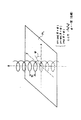
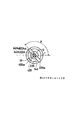
まずその前に、図1に基づき、ネジの形状と位相との関係について説明する。通常のネジは、ネジ径(有効径)やピッチのみで規定される。ところで、ネジの形状は螺旋を描く。つまり、ネジの特定部位、例えばネジ山の頂の座標をたどると、図1に示すように、螺旋を描く。
ここで、螺旋形状は一般に、基準平面PLをx−y(r−θ)平面とし、これに垂直な軸をz軸とすると、x=r・cos(θ+ψ)、y=r・sin(θ+ψ)、z=p(θ+ψ)で表される。ここで、r2=x2+y2 、θはx軸から測った基準平面PL上の角度、ψは定数の位相であり、pはネジのピッチである。この式から判るように、通常のネジの規格において、rやpは規定されているが、位相ψは規定されていないので、螺旋の形状は定まらないことになる。従って、このようなネジを持つ点火プラグとシリンダーヘッドとを組み合わせれば、外側電極固着部の位置は、定まらず、一周360度の範囲内でバラツクことになる。そこで、以下のように、位相ψがある範囲内に限定された雄ネジを持つ点火プラグ、および雌ネジを持つシリンダーヘッドを用いればよい。
【0035】
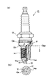
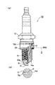
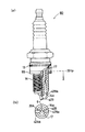
まず、点火プラグについて説明する。図2に示す、本実施形態の点火プラグ10は、外側電極12が1つのみ形成された、いわゆる1極タイプで、主体金具13の径大本体部13aに設けられたテーパ面を構成するプラグ座面13tによってシールを行ういわゆるコニカルシートタイプのものである。このプラグ10は、中心電極16の周囲を取り囲む絶縁碍子17と、その図中下部を保持する主体金具13とを有し、主体金具13は、径大本体部13a、および雄ネジ(M14×1.25)が形成された取付ネジ部14を備え、取付ネジ部14の先端部14aには、外側電極12の固着部12aが固着されている。この外側電極12は、図2(b)に示すように、固着部12aにおいて、リング状の先端部14aに固着され、その先端は、リングの中心に向かって延び、図2(a)に示すように、略L字状に曲げられて中心電極16と所定の放電ギャップを形成するようにされている。
【0036】
本実施形態のプラグ10は、取付ネジ部14の形成されたネジの位相ψと、外側電極14の位置とにある関係を持たせてある。その関係を以下に説明する。
まず、ネジの位相ψの代わりに、プラグ座面13tから所定距離にあるネジの特定部位の位置を特定する。位相ψは、基準平面PLの取り方によって変わるので、現実のプラグ等においては、基準平面PLを定め、位相ψを求めなくとも、ネジの形状と外側電極固着部との相対的な位置関係を決めるだけで、足りるからである。
【0037】
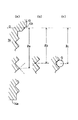
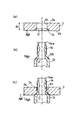
本実施形態のプラグ10はコニカルシートタイプであるので、ISO規格によって、プラグ座面13tからの寸法測定の基準が定められており、具体的には、所定の径D(本例では、φ14.8mm:ISO 2344:1992(E)参照)を有するゲージングプレーン13gpが基準である。そこで、このゲージングプレーン13gpを基準として、ネジ山の雄ネジの特定部位までの距離Zを測定する。例えば、図3(a)では、ネジ山の2つの斜面の延長面(延長線)が交差するネジ山の頂を算出し、ゲージングプレーン13gpまでの距離Zaを算出する。また、図3(b)では、ネジの谷の2つの斜面の延長面(延長線)が交差するネジの谷底を算出し、ゲージングプレーン13gpまでの距離Zbを算出する。図3(c)では、雄ネジの有効径を測定するときに用いる丸棒状ネジゲージGを2つのネジ山の斜面に当接させ、2つのネジ山の斜面の略中央に相当するゲージGの図中右側の頂部を検出し、2つのネジ山の斜面の中央からゲージングプレーン13gpまでの距離Zcを算出する。このような手法により、基準であるゲージングプレーン13gpからネジの特定部位までの距離Zを測定する。なおこれらの測定においては、画像処理技術によってネジ山の頂や谷底などを求めると容易に算出できる。
【0038】
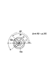
ここで、この距離Zが所定距離、例えば5mmとなる特定部位の位置、例えば、図3(a)に示すような方法によって測定したネジ山の頂までの距離Zaがちょうど5mmとなる位置が、ネジを周方向に一周(360度)観察することによって、検出できる。この周方向位置Tを基準として、図4に示すように、点火プラグ10の先端側から見て、先端部14aの中心Oとを結ぶ基準線O−Tから、外側電極固着部12aまでの角度θを反時計方向に測定する。例えば、外側電極固着部12aが実線で示される位置にある場合には、この固着部12aの周方向角度は、θ1で表される。同様に破線の場合には、θ2で表される。
【0039】
このような測定方法によって、固着部12aの周方向角度θ(deg)を測定したとき、本実施形態のプラグ10は、いずれも、θ=α+50〜α+310の角度範囲内、即ち、θ=α−50〜α+50の範囲を除く周方向角度範囲内に収まるように、外側電極12が固着されている。ここで、αは0〜360の定数である。従って、外側電極12との関係において、取付ネジ部14に形成された雄ネジは、その位相ψがとりうる値(360度)のうち、260度(=310-50=360-(50-(-50)))の範囲に限定された形状となっている。
【0040】
ついで、シリンダーヘッド110について説明する。図5に示すように、このシリンダーヘッド110には、プラグ10を取り付けるためのプラグ取付孔111を備える。この取付孔111の形状は、ISO規格(ISO 2344:1992(E))において与えられた形状とされており、60度のテーパ面とされたプラグ取付座113、および取付ネジ部114(本例では、M14S×1.25)を備える。なお、プラグ取付座113においては、所定の径D(本例では、φ14.8mm)となるゲージングプレーン113gpが各寸法の基準とされている。この取付ネジ部の雌ネジは、ネジの呼ビ(M14)およびピッチ(1.25)のみが与えられているばかりでなく、雌ネジの位相が、各シリンダーヘッド間で略同一に揃えられている。即ち、例えば、この雌ネジを仮想的に延ばしたときに、ゲージングプレーン113gpとネジの特定部分(例えば、ネジ山の頂など)とが交差する位置を見ると、いずれのシリンダーヘッド110に形成された雌ネジについても、略同一の位置で交差するように形成されている。
【0041】
ところで、シリンダーヘッド110に、上記プラグ10を取り付けた場合の、締付トルクTqとプラグの回転角Agとの関係を調査したところ、図6のようになった。即ち、トルク10N・mで締め付けたとき、プラグ10の回転角Agは、10〜33度の範囲内に分布した。また、同様に、15及び20N・mでは、それぞれ18〜40度、および20〜48度の範囲に分布した。適正締付トルク10〜20N・mの範囲全体においてみると、回転角Agは、10〜48度(29±19度)の範囲内に分布し、回転角AgのバラツキG1は、±19度である。従って、コニカルシートタイプのプラグの回転角のバラツキG1は、最大±20度を見込めば足りる。
従って、図7(a)に示すように、上記シリンダーヘッド110を備えるエンジン210に、上記プラグ10を取り付けた場合には、回転角AgのバラツキG1も考慮すると、このプラグ10をその先端側から見たとき、外側電極固着部12aの位置は、θ=α+30(50-20)〜α+330(310+20)の範囲、つまり、300度(=330-30=260+20-(-20 ))の周方向角度範囲内に収まる。即ち、一周のうち、外側電極固着部12aが位置することのない、角度にして60度(=±30度=360-300)の特定の範囲が存在することになる。
【0042】
そこで、インテークバルブ211から入った混合気が、スワールM2となって図示するように(図中右から左に向かって)流れた場合を考える。ここで、先端側から見て、スワールM2が取付ネジ部先端部14aの中心Oを通る流線Lmと、先端部14aとの交点のうち上流側の交点Sを基準として、この特定範囲の中心がこの基準線O−Sに重なるように、プラグ10の雄ネジおよびシリンダーヘッド110の雌ネジの位相を選択する。すると、スワールM2と外側電極12の固着部12aとの関係は、図7(b)に示すようになる。即ち、例えば、実線で示す位置に外側電極固着部12aが位置している場合、交点Sを基準として反時計方向に測った径方向角度θeは、θe1(=180度)で表される。また同様に、破線で示す位置の場合には、それぞれθe2、θe3となる。しかし、基準線O−Sを中心として±30度の範囲(O−U2〜O−U1)内には、外側電極固着部12aが位置せず、θ(deg)=30〜330の範囲内に限定される。
従って、前記したように(図23参照)、外側電極固着部12aがスワールM2の上流側に位置しないので、スワールM2の流れを妨害することが無く、外側電極12と中心電極16との間の放電領域での放電で、確実にスワールM2に着火させることができる。このため、薄い混合気(高いA/F値)でもエンジン210を駆動することができ、燃費を向上させることができる。
【0043】
(実施形態2)
ついで、第2の実施の形態として、図8に示す、対向する2つの外側電極22A,Bを有する2極コニカルシートタイプのプラグ20の場合について説明する。本実施形態は、上記実施形態1に比較して、外側電極が2つ(22A,B)になり、しかも、これらが互いに180度ずれた位置にある点のみ異なるので、異なる部分について説明し、同様な部分は省略する。
このような2極のプラグにおいても、実施形態1と同様に、ゲージングプレーン13gpを基準に、取付ネジ部14の雄ネジの特定部位(例えば、ネジ山の頂)までの距離Z(Za)が、所定距離(例えば、5mm)となる周方向位置Tを見つけだす。ついで、この周方向位置Tを基準として、図9に示すように、点火プラグ20の先端側から見て、先端部14aの中心Oとを結ぶ基準線O−Tから、外側電極固着部22Aaまでの角度θを反時計方向に測定する。
【0044】
このような測定方法によって、固着部22Aa,22Baの周方向角度θ(deg)を測定したとき、本実施形態のプラグ20は、いずれも、θ=α+50〜α+310の角度範囲内に収まるようにされている。従って、外側電極固着部22Aaの周方向角度θは、θ=α+50〜α+130の周方向角度範囲内に、対向する他方の外側電極固着部22Baが、θ=α+230〜310の周方向角度範囲内に収まるように、外側電極22A,22Bが固着されている。ここで、αは0〜360の定数である。従って、外側電極22A,22Bとの関係において、取付ネジ部14に形成された雄ネジは、その位相ψがとりうる値(360度)のうち、50〜130度および230〜310度の範囲に限定された形状となっている。
【0045】
上記した点火プラグ20を、実施形態1において用いたシリンダーヘッド110を備えるエンジン210に取り付けた場合、適正締付トルク10〜20N・mに見込まれる回転角AgのバラツキG1(最大±20度、図6参照)も考慮すると、このプラグ20をその先端側から見たとき、外側電極固着部22Aa,22Baの位置は、それぞれ、θ=α+30(50-20)〜α+150(130+20 )度、およびα+210(230-20)〜α+330(310+20)度の周方向角度範囲内に収まる。即ち、一周のうち、外側電極固着部22Aa,22Baが位置することのない、角度にして60度(=±30度=30(390)-330,210-150)の特定の範囲が2つ存在することになる。
【0046】
そこで、図7(b)に示すように、スワールM2が取付ネジ部先端部14aの中心Oを通る流線Lmと、先端部14aとの交点のうち上流側の交点Sを基準として、この特定範囲の中心がこの基準線O−Sに重なるように、プラグ20の雄ネジおよびシリンダーヘッド110の雌ネジの位相を選択する。すると、基準線O−Sを中心として±30度の範囲内(O−U2〜O−U1)内には、外側電極固着部22Aa,22Baが位置しない。
従って、本実施形態2においても、前記したように(図24参照)、外側電極固着部22Aa,22BaaがスワールM2の上流側に位置しないので、スワールM2の流れを妨害することが無く、外側電極22A,Bと中心電極16との間の放電領域での放電で、確実にスワールM2に着火させることができる。このため、薄い混合気(高いA/F値)でもエンジン210を駆動することができ、燃費を向上させることができる。
【0047】
(実施形態3)
ついで、第3の実施の形態として、図10に示す、1つの外側電極12を有する1極フラットシートタイプのプラグ30の場合について説明する。本実施形態は、上記実施形態1に比較すると、テーパ面のプラグ座面13tではなく、径大本体部13aの図中下端が、軸に垂直で平坦なプラグ座面33fpとされ、図11(a)に示すように、シリンダーヘッド130との間に、金属板を折り曲げて形成した金属板折曲リングガスケット35を介在させてシールするものである。従って、ゲージングプレーン13gpを基準とせず、プラグ座面33fpを基準とする点、および、プラグ座面(テーパ面)13tで直接シールせず、ガスケット35をプラグ座面33fpに当接させる点でのみ異なり、特にプラグ30の先端部における取付ネジ部先端部14aや外側電極12の形状は、実施形態1と同様であるので、異なる部分について説明し、同様な部分は省略する。
【0048】
上記実施形態1と同様に、ネジの位相ψを求めるのではなく、プラグ座面を基準としてネジの特定部位までの距離と測るのであるが、上記実施形態1とは異なり、図12に示すように、径大本体部13aの下端のプラグ座面33fpを基準として測定する。なお、特定部位までの距離として、図12(a)ではネジ山の頂までの距離Za、図12(b)ではネジの谷底までの距離Zb、図12(c)ではゲージGの図中右側の頂部までの距離Zcを測定する様子を示す。
このようにして、実施形態1と同様に、プラグ座面33fpを基準に、取付ネジ部14の雄ネジの特定部位(例えば、ネジ山の頂)までの距離Z(例えば、Za)が、所定距離(例えば、5mm)となる周方向位置T(図4参照)を見つけだす。ついで、この周方向位置Tを基準として、点火プラグ30の先端側から見て、先端部14aの中心Oとを結ぶ基準線O−Tから、外側電極固着部12aまでの角度θを反時計方向に測定する。
【0049】
このような測定方法によって、固着部12aの周方向角度θ(deg)を測定したとき、本実施形態のプラグ30は、いずれも、θ=α+90〜α+270の角度範囲内に収まるように、外側電極12が固着されている。ここで、αは0〜360の定数である。従って、外側電極12との関係において、取付ネジ部14に形成された雄ネジは、その位相ψがとりうる値(360度)のうち、90〜270度の範囲に限定された形状となっている。
【0050】
図11(a)に示すように、規格(ISO 1919:1988(E))によって定められた形状のプラグ取付孔を有するシリンダーヘッド130を用意し、これを備えるエンジン230に、上記した点火プラグ30を取り付ける。この場合、本実施形態では、Fe製の金属板折曲リングガスケット35を用いているので、締付トルクTqとプラグの回転角Agとの関係を調査すると、は、ネジがM14Sの場合、図12のようになった。ここで、シリンダーヘッドがアルミ製の場合の適正トルクは20〜30N・m、鋳鉄製の場合は20〜40N・mとされているので(ISO 1919:1988(E))、その幅の大きな方の適正締付トルク20〜40N・mの範囲において、回転角Agは、160〜275(217.5±57.5 )度の範囲内に分布する。つまり、バラツキG3aは、±57.5度である。また、この他に、現在実用化されているM12S、M10Sの雄ネジをもつプラグについてもそれぞれ調査すると、適正締付トルク10〜15および15〜25N・mの範囲で、回転角Agは、それぞれ190〜266度(228±38度)及び170〜279度(224.5±54.5 度) の範囲内に分布した。つまり、バラツキG3b,G3cは、それぞれ±38度、および54.5度である。従って、これらのバラツキG3a,G3b,G3cの大きさから考えて、金属板折曲リングガスケット35を用いた場合には、回転角AgのバラツキG3は、最大±60度を見込めば足りる。
【0051】
そこで、この回転角AgのバラツキG3(最大±60度)も考慮すると、このプラグ30をその先端側から見たとき、外側電極固着部12aの位置は、それぞれ、θ=α+30(90-60)〜α+330(270+60 )度の周方向角度範囲内に収まる。即ち、一周のうち、外側電極固着部12aが位置することのない、角度にして60度(=±30度=30(390)-330)の特定の範囲が存在することになる。
【0052】
そこで、図11(b)に示すように、スワールM2が取付ネジ部先端部14aの中心Oを通る流線Lmと、先端部14aとの交点のうち上流側の交点Sを基準として、この特定範囲の中心がこの基準線O−Sに重なるように、プラグ30の雄ネジおよびシリンダーヘッド130の雌ネジの位相を選択する。すると、基準線O−Sを中心として±30度の範囲内(O−U2〜O−U1)内には、外側電極固着部12aが位置しない。
従って、前記したように(図23参照)、外側電極固着部12aがスワールM2の上流側に位置しないので、スワールM2の流れを妨害することが無く、外側電極12と中心電極16との間の放電領域での放電で、確実にスワールM2に着火させることができる。このため、薄い混合気でもエンジン210を駆動することができ、燃費を向上させることができる。
【0053】
(実施形態4)
ついで、第4の実施の形態として、図14に示す、2つの外側電極22A,Bを有する2極フラットシートタイプのプラグ40の場合について説明する。本実施形態は、上記実施形態3と同様に、径大本体部13aの図中下端が、軸に垂直なプラグ座面33fpとされ、シリンダーヘッド130(図11(a)参照)との間に、金属板折曲リングガスケット35を介在させてシールするものである。一方、プラグ40の先端部分は、上記実施形態2と同様に、外側電極を2つ(42A,42B)有するが、これらが互いに90度ずれた位置にある点で異なるので、実施形態2および3と異なる部分を中心に説明し、同様な部分は省略する。
【0054】
本実施形態も実施形態3と同様に、径大本体部13aの下端のプラグ座面33fpを基準として特定部位までの距離を測定する(図12参照)。即ち、プラグ座面33fpを基準に、取付ネジ部14の雄ネジの特定部位(例えば、ネジ山の頂)までの距離Z(例えば、Za)が、所定距離(例えば、5mm)となる周方向位置Tを見つけだす。ついで、この周方向位置Tを基準として、図9に示すように、点火プラグ40の先端側から見て、先端部14aの中心Oとを結ぶ基準線O−Tから、外側電極固着部42Aa,42Baまでの角度θを反時計方向に測定する。
【0055】
このような測定方法によって、固着部42Aa,42Baの周方向角度θ(deg)を測定すると、上記実施形態3と同様に、固着部42Aa,42Baはいずれも、θ=α+90〜α+270の角度範囲内に収まるようにされている。つまり、固着部42Aaは、θ=α+90〜α+180の角度範囲内に収まり、他方の外側電極固着部42Baは、θ=α+180〜270の周方向角度範囲内に収まるように、外側電極42A,42Bが固着されている。ここで、αは0〜360の定数である。従って、外側電極42A,42Bとの関係において、取付ネジ部14に形成された雄ネジは、その位相ψがとりうる値(360度)のうち、90度の範囲に限定された形状となっている。
【0056】
図11(a)に示すように、上記した点火プラグ40を、実施形態3において用いたシリンダーヘッド130を備えるエンジン230に取り付けた場合、実施形態3と同様に、Fe製の金属板折曲リングガスケット35を用いているので、図12に示す結果から、回転角AgのバラツキG3は、最大±60度見込まれる。そこで、この回転角AgのバラツキG3(最大±60度)も考慮すると、このプラグ40をその先端側から見たとき、外側電極固着部42Aa,42Baの位置は、それぞれ、30(90-60)〜240(180+60)度、および120(180-60 )〜330(270+60)度の周方向角度範囲内に収まる。即ち、一周のうち、外側電極固着部42Aa,42Baが位置することのない、角度にして60度(=±30度=30(390)-330)の特定の範囲が存在することになる。
【0057】
そこで、図11(b)に示すように、スワールM2が取付ネジ部先端部14aの中心Oを通る流線Lmと、先端部14aとの交点のうち上流側の交点Sを基準として、この特定範囲の中心がこの基準線O−Sに重なるように、プラグ20の雄ネジおよびシリンダーヘッド130の雌ネジの位相を選択する。すると、基準線O−Sを中心として±30度の範囲内(O−U2〜O−U1)内には、外側電極固着部42Aa,42Baが位置しない。
従って、前記したように(図24参照)、外側電極固着部42Aa,42BaがスワールM2の上流側に位置しないので、スワールM2の流れを妨害することが無く、外側電極42A,42Bと中心電極16との間の放電領域での放電で、確実にスワールM2に着火させることができる。このため、高いA/F値までエンジン230を駆動することができ、燃費を向上させることができる。
【0058】
(実施形態5)
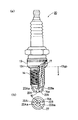
ついで、第5の実施の形態として、図15に示す、1つの外側電極12を有する1極フラットシートタイプのプラグ50の場合について説明する。本実施形態は、上記実施形態3に比較すると、軸に垂直で平坦なプラグ座面33fpに当接するリングガスケットが中実Oリングガスケット55となっている点で異なっているものである。従って、プラグ50の先端部における取付ネジ部先端部14aや外側電極12の形状は、実施形態3と同様であるので、異なる部分について説明し、同様な部分は省略する。
【0059】
実施形態3において、図11を参照して説明したのと同様に、プラグ座面33fpを基準に、取付ネジ部14の雄ネジの特定部位(例えば、ネジ山の頂)までの距離Z(例えば、Za)が、所定距離(例えば、5mm)となる周方向位置T(図4参照)を見つけだす。ついで、この周方向位置Tを基準として、点火プラグ30の先端側から見て、先端部14aの中心Oとを結ぶ基準線O−Tから、外側電極固着部12aまでの角度θを反時計方向に測定する。
【0060】
このような測定方法によって、固着部12aの周方向角度θ(deg)を測定したとき、本実施形態のプラグ50は、いずれも、θ=α+55〜α+305の角度範囲内に収まるように、外側電極12が固着されている。ここで、αは0〜360の定数である。従って、外側電極12との関係において、取付ネジ部14に形成された雄ネジは、その位相ψがとりうる値(360度)のうち、55〜305度の範囲に限定された形状となっている。
【0061】
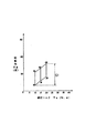
図11(a)に示すように、規格(ISO 1919:1988(E))によって定められた形状のプラグ取付孔を有するシリンダーヘッド130を用意し、これを備えるエンジン250に、上記した点火プラグ50取り付ける。この場合、本実施形態では、上記実施形態3,4で用いた中空の金属板折曲リングガスケットと異なり、Cu製中実Oリングガスケット55を用いているので、締付トルクTqとプラグの回転角Agを調査すると、ネジがM14Sの場合、図16のようになる。ここで、シリンダーヘッドがアルミ製の場合の適正トルクは20〜30N・m、鋳鉄製の場合は20〜40N・mとされているので(ISO 1919:1988(E))、その幅の大きな方の適正締付トルク20〜40N・mの範囲において、回転角Agは、バラツキも含めて15〜57(36±21)度の範囲内に分布する。つまり、回転角のバラツキG5aは、±21度である。
また、この他に実用化されているM12S,M10Sの雄ネジを持つプラグについても、同様に調査すると、適正締付トルク10〜15、15〜25N・mの範囲で、回転角Agは、16〜57(36.5±20.5)度、および18〜62(40±22)度の範囲に分布した。つまり、回転角のバラツキG5b、G5cは、それぞれ±20.5度、および±22度である。したがって、これらのバラツキG5a,G5b,G5cの値から、中実Oリングガスケットを用いた場合の回転角AgのバラツキG5は、最大±25度を見込めば足りる。
【0062】
そこで、この回転角AgのバラツキG5(最大±25度)も考慮すると、このプラグ50をその先端側から見たとき、外側電極固着部12aの位置は、それぞれ、θ=α+30(55-25)〜α+330(305+25 )度の周方向角度範囲内に収まる。即ち、一周のうち、外側電極固着部12aが位置することのない、角度にして60度(=±30度=30(390)-330)の特定の範囲が存在することになる。
【0063】
そこで、図11(b)に示すように、スワールM2が取付ネジ部先端部14aの中心Oを通る流線Lmと、先端部14aとの交点のうち上流側の交点Sを基準として、この特定範囲の中心がこの基準線O−Sに重なるように、プラグ50の雄ネジおよびシリンダーヘッド130の雌ネジの位相を選択する。すると、基準線O−Sを中心として±30度の範囲内(O−U2〜O−U1)内には、外側電極固着部12aが位置しない。
従って、前記したように(図23参照)、外側電極固着部12aがスワールM2の上流側に位置しないので、スワールM2の流れを妨害することが無く、外側電極12と中心電極16との間の放電領域での放電で、確実にスワールM2に着火させることができる。このため、薄い混合気でもエンジン250を駆動することができ、燃費を向上させることができる。
【0064】
(実施形態6)
ついで、第6の実施の形態として、図17に示す、対向する2つの外側電極22A,Bを有する2極フラットシートタイプのプラグ60の場合について説明する。本実施形態は、上記実施形態5と同様に、径大本体部13aの図中下端が、軸に垂直なプラグ座面33fpとされ、シリンダーヘッド130との間に、中実Oリングガスケット55を介在させてシールするものである。一方、プラグ60の先端部分は、上記実施形態2と同様に、外側電極が2つ(22A,22B)になり、しかも、これらが互いに180度ずれた位置にあるので、実施形態2および5と異なる部分を中心に説明し、同様な部分は省略する。
【0065】
本実施形態も実施形態3〜5と同様に、径大本体部13aの下端のプラグ座面33fpを基準として特定部位までの距離を測定する(図12参照)。即ち、プラグ座面33fpを基準に、取付ネジ部14の雄ネジの特定部位(例えば、ネジ山の頂)までの距離Z(例えば、Za)が、所定距離(例えば、5mm)となる周方向位置Tを見つけだす。ついで、この周方向位置Tを基準として、図9に示すように、点火プラグ60の先端側から見て、先端部14aの中心Oとを結ぶ基準線O−Tから、いずれか一方の外側電極固着部22Aaまでの角度θを反時計方向に測定する。
【0066】
このような測定方法によって、固着部22Aaの周方向角度θ(deg)を測定すると、固着部22Aaは、θ=α+55〜α+125の角度範囲内に収まり、他方の外側電極固着部22Baは、θ=α+235〜α+305の周方向角度範囲内に収まるように、外側電極22A,22Bが固着されている。ここで、αは0〜360の定数である。従って、外側電極22A,22Bとの関係において、取付ネジ部14に形成された雄ネジは、その位相ψがとりうる値(360度)のうち、55〜125度および235〜305度の範囲に限定された形状となっている。
【0067】
図11(a)に示すように、上記した点火プラグ60を、実施形態5において用いたシリンダーヘッド130を備えるエンジン250に取り付けた場合、実施形態5と同様に、Cu製の中実Oリングガスケット55を用いているので、図16に示す結果から、回転角AgのバラツキG5は、最大±25度と見込まれる。そこで、この回転角AgのバラツキG5(最大±25度)も考慮すると、このプラグ60をその先端側から見たとき、外側電極固着部22Aa,22Baの位置は、それぞれ、30(55-25)〜150(125+25)度、および210(235-25 )〜330(305+25)度の周方向角度範囲内に収まる。即ち、一周のうち、外側電極固着部22Aa,22Baが位置することのない、角度にして60度(=±30度=30(390)-330,210-150)の特定の範囲が2つ存在することになる。
【0068】
そこで、図11(b)に示すように、スワールM2が取付ネジ部先端部14aの中心Oを通る流線Lmと、先端部14aとの交点のうち上流側の交点Sを基準として、この特定範囲の中心がこの基準線O−Sに重なるように、プラグ60の雄ネジおよびシリンダーヘッド130の雌ネジの位相を選択する。すると、基準線O−Sを中心として±30度の範囲内(O−U2〜O−U1)内には、外側電極固着部22Aa,22Baが位置しない。
従って、前記したように(図23参照)、外側電極固着部22Aa,22BaaがスワールM2の上流側に位置しないので、スワールM2の流れを妨害することが無く、外側電極22A,Bと中心電極16との間の放電領域での放電で、確実にスワールM2に着火させることができる。このため、薄い混合気でもエンジン250を駆動することができ、燃費を向上させることができる。
【0069】
ついで、上記各実施形態で示した点火プラグ10〜60の製造方法について説明する。上記点火プラグ10等は、通常の点火プラグと同様の製法で製造され、外側電極12、22A,22B,42A,42Bを主体金具13の取付ネジ部先端部14aに固着する工程のみ異なるので、異なる部分のみ説明する。まず、コニカルシートタイプの点火プラグ10,20(実施形態1,2)について説明する。
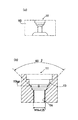
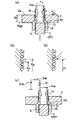
コニカルシートタイプの場合には、上記したように寸法の基準となるゲージングプレーン13gpを簡便に得にくいため、まず、図18(a)に示すように、表面Jaおよびこれに平行な裏面Jbを備え、貫通孔Jhがこの表・裏面Ja,Jb間を垂直に貫通し、貫通孔Jhと裏面Jbとの角部に、当接テーパ面Jtが形成された当接具Jを用意する。この当接テーパ面Jtは、前述したテーパ面のプラグ座面13tに適合した形状に形成され、具体的には、前述したコニカルシールタイプのプラグの規格(例えば、ISO 2344:1992(E))に準じたテーパ面の形状に形成されている。従って、所定の直径D(例えば、14.8mm)を有するゲージングプレーンJgpを基準として寸法を測定することができ、ゲージングプレーンJgpから表面Jaまでの距離は、Z0とされている。
【0070】
この当接具Jの裏面Jb側から、図18(b)に示す、取付ネジ部14が形成された主体金具13を挿入する(図18(c)参照)。この取付ネジ部14の雄ネジは、例えば、転造によって形成され、ネジ形成後、主体金具は、通箱等に集積されるので、雄ネジの位相は定まっていない。当接具Jの貫通孔Jhの直径は、主体金具13の取付ネジ部14のネジ外径よりもやや大きくされているため、取付ネジ部14が遊嵌状に挿入でき、テーパ面となっているプラグ座面13tと当接具Jの当接テーパ面Jtとが当接したところで止まる。これにより、当接具JのゲージングプレーンJgpと主体金具13のゲージングプレーン13gpとが一致する。
【0071】
ついで、図19(a)に示すように、図中下方から、主体金属13内部にCuからなる接地電極体Kを挿入し、図中上方に押し上げて、プラグ座面13tと当接具Jの当接テーパ面Jtとを所定圧力で当接させる。圧力を掛けて両者を当接させるのは、実際にシリンダーヘッド110のプラグ取付孔111に取り付けた場合の圧力に近似した状態で外側電極12の固着部位を決定するため、および、後述する抵抗溶接において、接地電極体Kと主体金具13との間の接触抵抗をできるだけ低くするためである。
接地電極体Kを挿入後、接地電極体Kを軸方向(図中上下方向)に回転させる。すると、図19(b)に示すように、取付ネジ部14は、回転に従って、そのネジ山が、実線で示した状態から破線で示す状態に移動するので、あるネジ山の頂を観察すると、実線で示す状態では、表面Jaからの距離Z1が、Z11であったのに対し、破線で示す状態になると、Z12に変化する。そこで、例えば、Z0=3mmの当接具Jを用いた場合、ちょうど距離Z1=2mmとなる位置で、接地電極体Kや主体金具13の回転を停止させる。これにより、ゲージングプレーン13gpから計測すると、Z0+Z1=3+2=5mmの距離にあるネジ山の頂が検出できたことになる。従って、このようにして、ゲージングプレーン13gpから所定距離(ここでは5mm)にあるネジの特定部位(本例ではネジ山の頂)を検出すれば、常に、各主体金具13のネジの位相を揃えた状態で主体金具13の回転を停止させることができる。
【0072】
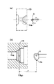
ついで、図19(c)に示すように、停止した状態の主体金具13の取付ネジ部先端部14aに、外側電極12の一端(図中下端)を当接させ、スイッチSWを投入して直流電源Edcから大電流を流し、抵抗溶接によって、先端部14aに外側電極12を固着させる。2極の場合には、180度ずれた位置にも外側電極22(22A,22B)を固着する。このように、接地電極体Kで主体金具13を押し上げたので、回転の停止後、直ちに外側電極12を溶接でき、ピースタイムを短くして、量産をすることができる。
なお、外側電極12を、回転を停止させた状態の主体金具13の先端部14aに対して、常に略同一の位置(例えば、図19(c)では、図中左端)で固着すれば足りる。
【0073】
その他、図19(d)に示すように、常に所定の高さZ1(例えばZ1=2mm)におけるネジの形状を観察すると、回転に従って、実線で示すようにネジの谷となったり、破線で示すようにネジ山の頂となったり形が変化するので、特定部位、例えば、ネジ山の頂の形状となったときに、接地電極体Kや主体金具13の回転を停止させても良い。このようにした場合には、多くとも1回転の間に、所望の形状となるので、検出が早い利点がある。
このようにして、外側電極12を固着した主体金具13は、以降、通常のプラグの組立工程を経て、プラグ10,20となる。
【0074】
上記では、コニカルシートタイプのプラグを用いて説明したが、フラットシートタイプのプラグ30,40、50,60の場合には、基準となるプラグ座面33fpが明確であるので、上記した当接具Jのごとき補助具は不要である。従って、プラグ座面33fpから直接、コニカルシートタイプの場合と同様に、所定距離(例えば、5mm)にあるネジの特定部位(例えば、ネジ山の頂)を検出すれば、常に、各主体金具13のネジの位相を揃えた状態で主体金具13の回転を停止させることができる。以降は、上記と同様にして、外側電極12を抵抗溶接によって固着すればよい。
なお、当接テーパ面Jtを形成しない当接具を補助的に用いて、プラグ座面33fpと裏面とを当接させ、表面からの高さを測定しても良いことは明らかである。
【0075】
ついで、上記各実施形態で示したシリンダーヘッドの製造方法について説明する。上記シリンダーヘッド110、130は、通常のシリンダーヘッドと同様の製法で製造され、プラグ取付孔111の取付ネジ部114の形成方法のみ異なるだけであるので、異なる部分のみ説明する。まず、コニカルシートタイプのプラグ10、20に適合するシリンダーヘッド110について説明する。
まず、公知の手法によって、図20(a)に示すように、鋳鉄製のシリンダーヘッド110を形成する。このシリンダーヘッド110には、前記したように、規格に基づくをプラグ取付孔111が形成されている。但し、プラグ取付ネジ部114のみ形成されておらず、その下孔114aのみ形成されて状態である。雌ネジを形成するには、シリンダーヘッド110を固定し、バイトHをその軸を中心に回転させながら1回転毎に所定ピッチ(本例では、1.25mm)ずつ図中左側に向けて送り、下孔114aを切削して、雌ネジを形成する。
【0076】
この際、図20(b)に示すように、テーパ面のプラグ取付座113の所定径D(本例では、14.8mm)となるゲージングプレーン113gpから、例えば、ちょうどバイトHの刃先Haが図中下向きとなったときの刃先Haまでの距離Fを一定値(例えば、10mm)とし、この状態から、バイトHを回転させると共に、回転に同期させて1回転当たり1ピッチの速度でバイトHを図中左方向に送る。すると、いずれのシリンダーヘッド110においても、下孔114aには、ゲージングプレーン113gpを基準としたときに、一定の位相を持つ螺旋形状の雌ネジが形成されることになる(図5参照)。
【0077】
上記では、コニカルシートタイプのプラグに適合するシリンダーヘッド110の製造方法について説明したが、フラットシートタイプのプラグ30,40、50,60に適合するシリンダーヘッド130の場合には、基準となるプラグ取付座を基準として、同様に雌ネジを形成すればよい。
なお、雌ネジの製造方法は、ネジの位相を各シリンダーヘッド間で略同一にできれば、公知の手法のいずれを用いても良い。
【0078】
以上において、本発明を実施形態に即して説明したが、本発明は上記実施形態に限定されるものではなく、その要旨を逸脱しない範囲で、適宜変更して適用できることはいうまでもない。
例えば、上記実施形態1,2、3,5,6では、外側電極が1極および対向する2極のプラグを示したが、実施形態4にも示すように、外側電極の数および位置はこれに限定されるものではない。例えば、回転角Agのバラツキが±30度(図6参照)の実施形態1,2と同様なコニカルシートタイプのプラグにおいて、図21に示すように、互いに90度ずつずれて形成された3つの外側電極72A,72B,72Cを備える3極のプラグ70を用いても良い。
いずれにしても、プラグ70をエンジンに取り付けたときに、取付時の回転角のバラツキも考慮した上で、スワールM2が取付ネジ部先端部14aの中心Oを通る流線Lmと、先端部14aとの交点のうち上流側の交点Sを基準として、この基準線O−Sを中心とする±30度の範囲(O−U2からO−U1内)に、各外側電極固着部72Aa,72Ba,72Ca等が入らないで、30〜330度の角度範囲内に位置するようにすればよい。
【図面の簡単な説明】
【図1】 ネジの螺旋と位相との関係を説明する説明図である。
【図2】 実施形態1にかかる1極コニカルシートタイプの点火プラグの形状を示す部分破断断面図およびプラグ先端近傍のみを示す底面図である。
【図3】 実施形態1にかかるプラグにおいて、プラグ座面13tのゲージングプレーン13gpからネジの各部位までの距離を測る様子を示す説明図であり、(a)はネジ山の頂、(b)はネジの谷底、(c)は2つのネジ山の斜面の中央、までの距離を測る様子を示す。
【図4】 点火プラグの外側電極固着部の周方向角度位置を計測する方法を示す説明図である。
【図5】 シリンダーヘッドのプラグ取付孔の形状を示す説明図である。
【図6】 コニカルシートタイプのプラグをシリンダーヘッドに取り付けたときの、締付トルクと回転角との関係を示すグラフである。
【図7】 シリンダーヘッドを有するエンジンに点火プラグを取り付けた状態を示す説明図であり、(a)は縦方向の部分破断断面図であり、(b)は点火プラグをその先端側から見た図である。
【図8】 実施形態2にかかる2極コニカルシートタイプの点火プラグの形状を示す部分破断断面図およびプラグ先端近傍のみを示す底面図である。
【図9】 実施形態2にかかる点火プラグの外側電極固着部の周方向角度位置を計測する方法を示す説明図である。
【図10】 実施形態3にかかる金属板折曲リングガスケットを備える1極フラットシートタイプの点火プラグの形状を示す部分破断断面図、およびプラグ先端近傍のみを示す底面図である。
【図11】 シリンダーヘッドを有するエンジンに点火プラグを取り付けた状態を示す説明図であり、(a)は縦方向の部分破断断面図であり、(b)は点火プラグをその先端側から見た図である。
【図12】 実施形態3にかかるプラグにおいて、プラグ座面33fpからネジの各部位までの距離を測る様子を示す説明図であり、(a)はネジ山の頂、(b)はネジの谷底、(c)は2つのネジ山の斜面の中央、までの距離を測る様子を示す。
【図13】 金属板折曲リングガスケットを備えるフラットシートタイプのプラグをシリンダーヘッドに取り付けたときの、締付トルクと回転角との関係解明を示すグラフである。
【図14】 実施形態4にかかる金属板折曲リングガスケットを備える2極フラットシートタイプの点火プラグの形状を示す部分破断断面図、およびプラグ先端近傍のみを示す底面図である。
【図15】 実施形態5にかかる中実Oリングガスケットを備える1極フラットシートタイプの点火プラグの形状を示す部分破断断面図、およびプラグ先端近傍のみを示す底面図である。
【図16】 中実Oリングガスケットを備えるフラットシートタイプのプラグをシリンダーヘッドに取り付けたときの、締付トルクと回転角との関係解明を示すグラフである。
【図17】 実施形態6にかかる中実Oリングガスケットを備える2極フラットシートタイプの点火プラグの形状を示す部分破断断面図、およびプラグ先端近傍のみを示す底面図である。
【図18】 主体金具の周方向固着基準位置を割り出す工程のうち、当接具の貫通孔に主体金具の取付ネジ部を挿入するまでを示す説明図であり、(a)は当接具の断面図を、(b)は主体金具のうちの先端部近傍の断面図を、(c)は当接具の貫通孔に主体金具の取付ネジ部を挿入した状態の断面図を示す。
【図19】 主体金具の周方向固着基準位置を割り出す工程および外側電極を溶接する工程のうち、(a)当接具に挿入された主体金具を回転させる状態を、(b)(d)は回転させた状態でネジの特定部位を検出する様子を、(c)は先端部に外側電極を溶接する様子を示す説明図である。
【図20】 シリンダーヘッドのプラグ取付孔の下孔に雌ネジを形成する状態を示す説明図である。
【図21】 他の実施形態の点火プラグのうち、プラグ先端近傍のみを示す底面図である。
【図22】 エンジンおよび点火プラグと混合気の流れ(スワール)の関係を示す説明図である。(a)はシリンダーの下方から見た状態、(b)は点火プラグとスワールとの関係を示す。
【図23】 1極点火プラグとスワールとの関係を説明する説明図であり、(a)はスワールと外側電極との角度θを説明する説明図であり、(b)は角度θを変えた場合に、限界A/F値の変化を示すグラフである。
【図24】 2極点火プラグとスワールとの関係を説明する説明図であり、(a)はスワールと外側電極との角度θを説明する説明図であり、(b)は角度θを変えた場合に、限界A/F値の変化を示すグラフである。
【符号の説明】
10,20,30,40,50,60 点火プラグ
12,22A,22B,42A,42B 外側電極
12a,22Aa,22Ba,42Aa,42Ba 固着部
13 主体金具
13a 径大本体部
13t,33fp プラグ座面
13gp,113gp,Jgp ゲージングプレーン
14 取付ネジ部
14a 先端部
16 中心電極
17 絶縁碍子
110,130 シリンダーヘッド
111 プラグ取付孔
113 プラグ取付座
114 プラグ取付ネジ部
210,230,250 エンジン[0001]
BACKGROUND OF THE INVENTION
The present invention relates to an internal combustion engine, an ignition plug used therefor, a cylinder head, and a method for manufacturing an internal combustion engine ignition plug, and more particularly, an internal combustion engine capable of improving fuel consumption, an ignition plug used therefor, a cylinder head, and The present invention relates to a method of manufacturing an ignition plug for an internal combustion engine.
[0002]
[Prior art]
In recent years, in order to improve fuel efficiency of internal combustion engines such as automobile engines, the internal combustion engines have been driven by lean burn or direct fuel injection. In such an internal combustion engine (hereinafter also simply referred to as an engine), it is desired to improve the ignitability of a spark plug (hereinafter also simply referred to as a plug) and to reliably ignite an air-fuel mixture.
By the way, in the conventional engine, the phase of the female screw formed in the plug mounting hole formed in the cylinder head and the male screw formed in the mounting screw portion of the metal shell of the plug is not particularly defined. Therefore, when the plug is screwed into the plug mounting hole, the circumferential position of the outer electrode fixed to the tip of the mounting screw exposed in the cylinder cannot be determined. That is, by the combination of the cylinder head and the plug, the circumferential position of the outer electrode can be any position within a range of 360 degrees.
[0003]
[Problems to be solved by the invention]
However, as described above, in the case of driving by lean burn or direct fuel injection, a rich (high fuel ratio) mixture flow (swirl) that can be ignited is formed, and the center electrode and the outer electrode of the plug Since the swirl is designed so that the swirl passes through the discharge region, if the fixing position of the outer electrode is on the upstream side of the swirl, it is difficult for the rich air-fuel mixture to flow into the discharge region, and misfire is likely to occur. Therefore, in this case, the engine can be driven only in a range where the A / F (Air / Fuel) value is relatively small, and the fuel consumption is reduced.
[0004]
For example, the following test was performed on a four-valve engine E as shown in FIG. In this engine E, the two valves IN1, 2 on the right side in the figure are on the intake (intake) side, and the two left valves EX1, 2 are on the exhaust (exhaust) side. At this time, the air-fuel mixture M1 indicated by the arrow supplied from the right side in the figure is led into the cylinder C from the valves IN1 and 2, and flows in the leftward swirl indicated by the arrow M2 in the center in the figure. The exhaust gas N1 is exhausted through the valves EX1 and EX2 as indicated by arrows. In addition, description of the plug P was abbreviate | omitted in Fig.22 (a). However, the x mark in the center of the cylinder C is the discharge region of the spark plug P. When this is viewed from the side of the engine E, it is as shown in FIG. 22 (b), and the swirl M2 has a discharge region between the center electrode PI and the outer electrode PO of the plug P attached to the cylinder head CH. It is made to pass.
[0005]
Using such an engine E, the limit A / F value was measured using the plug P in which the circumferential position of the fixing portion POa of the outer electrode PO was changed. First, the case where the spark plug P having one pole (one outer electrode PO) is used will be described. As shown in FIG. 23 (a), when viewed from the tip end side in the axial direction of the plug P, the intersection of the stream line Lm of the swirl M2 passing through the center O of the tip end portion PTe of the attachment screw portion and the tip end portion PTe of the attachment screw portion. Among them, the circumferential position of the fixed portion POa of the outer electrode PO fixed to the mounting screw tip end portion PTe when measured in the counterclockwise direction with the upstream intersection S as a reference is indicated by an angle θ (deg). .
[0006]
Then, as shown in FIG. 23B, the limit A / F value was almost constant (a1) except for the range of θ = -30 to 30, but in the range of θ = -30 to 30, The limit A / F value decreases, and when θ = 0, the limit A / F value decreases to a2. That is, in this range, it can be understood that the operation is not performed unless the air-fuel mixture is relatively rich. This is considered to be because the swirl M2 is prevented from passing through the discharge region between the center electrode PI and the outer electrode PO because the fixing portion POa of the outer electrode PO is on the upstream side of the swirl M2.
Therefore, in order to enable the engine E to operate at any angle θ, that is, in any circumferential position of the fixing portion POa of the outer electrode PO, the limit A / F value is limited to a2 value. It cannot be used.
In addition, as a measuring method of the limit A / F value, the following method was used. That is, the plug P is attached and the angle θ is measured, and then the engine E is operated, and the air-fuel mixture is gradually thinned to increase the A / F value. Then, the plug P misfires, and the rotational speed of the engine E starts to fluctuate. Therefore, the A / F value when the fluctuation of the rotational speed becomes 10% is set as the limit A / F value. This was measured for various angles θ by replacing the plug P, and the graph shown in FIG. 23B was obtained.
[0007]
Similarly, measurement was performed using a two-pole spark plug P having two outer electrodes PO1, 2 fixed at positions different from each other by 180 degrees. The method for determining the angle θ is the same as in the case of one pole. That is, as shown in FIG. 24A, when viewed from the tip end side in the axial direction of the plug P, the streamline Lm of the swirl M2 passing through the center O of the attachment screw portion tip portion PTe, the attachment screw portion tip portion PTe, The position in the circumferential direction of the fixed portion POa of the outer electrode PO fixed to the mounting screw tip end portion PTe is indicated by an angle θ (deg) with respect to the intersection S on the upstream side.
[0008]
Then, as shown in FIG. 24B, the value of the limit A / F is substantially constant (a3) except for the ranges of θ = −30 to 30 and θ = 150 to 210 (= −150 to −210). However, in the range of θ = -30 to 30 and 150 to 210, the limit A / F value decreases, and in the case of θ = 0 and 180, the limit A / F value decreases to a4. That is, in this range, it can be understood that the operation is not performed unless the air-fuel mixture is relatively rich.
Therefore, in order to enable the engine E to operate at any angle θ, that is, in any circumferential position of the fixing portions PO1a and PO2a of the outer electrodes PO1 and PO2, a4 is set as a limit A / F value. It can only be used up to the value of. Here, in order to adjust the position of the outer electrode PO of the plug P to a desired position, a method of adjusting the tightening torque of the plug P can be considered, but an appropriate tightening torque is determined for tightening the plug ( For example, ISO 1919: 1988 (E) etc.) cannot always be adjusted, and in the case of insufficient torque or excessive tightening, the function of the plug may not be achieved.
[0009]
The present invention has been made in view of the above-described problems. An internal combustion engine that can be driven even with a thin air-fuel mixture (high A / F value) and has good fuel consumption, and an ignition plug and a cylinder head suitable for the internal combustion engine are provided. Furthermore, it aims at providing the manufacturing method of such a spark plug.
001 0 ]
[Means, actions and effects for solving the problems]
But then The solution includes a large-diameter main body portion having a tapered plug seat surface, and a male screw extending in the axial direction from the large-diameter main body portion and screwed into a plug mounting hole provided in a cylinder head for an internal combustion engine. An ignition plug for an internal combustion engine, comprising: a metal shell having an engraved mounting screw portion; and one or a plurality of outer electrodes fixed to a distal end portion of the mounting screw portion. When the internal combustion engine ignition plug is viewed, any internal combustion engine ignition plug is predetermined in the axial direction from the gauging plane of the plug seat surface among specific parts such as the top and bottom of the thread of the male screw. When α (deg) is a constant with the circumferential position of the specific part at a position separated by a distance as a reference, θ (deg) = α−50 to α + 50 of the tip of the mounting screw portion is represented. Circumferential angle, excluding angle range The distal end of the range, an internal combustion engine ignition plug, characterized in that none of the outer electrodes is secured.
001 1 ]
According to the spark plug of the present invention having the above-described configuration, it is a conical seat type spark plug that performs sealing with a tapered plug seat surface, and for any internal combustion engine spark plug of the same product number, the circumferential direction from the reference All of the outer electrodes are fixed to the tip in the circumferential angle range excluding the angle range of θ = α−50 to α + 50. That is, any one of the outer electrodes is fixed within a range of 260 degrees except for a range of 100 degrees (−50 to +50) out of 360 degrees per round.
For this reason, if a female screw that matches the male screw of the ignition plug is formed in the plug mounting hole of the cylinder head, and the female screw phase is substantially the same for each cylinder head, any of the female screws is formed. Even if the spark plug is screwed into the cylinder head, the position of the outer electrode fixing portion is within the range of about 260 degrees in the internal combustion engine. Furthermore, since the spark plug of the present invention is of a conical seat type, the variation in rotational angle that occurs when obtaining an appropriate tightening torque is small, and is ± 20 degrees at the maximum. Therefore, the outer electrode fixing portion is located within a range of 300 degrees (= 260 + (20 − (− 20))) even if the variation in the rotation angle during tightening is taken into consideration. That is, no matter which spark plug is attached to the cylinder head, a range of 60 degrees (± 30 degrees) is generated as a range in which the outer electrode fixing portion is not located.
001 2 ]
Therefore, if the phase of the female screw of the cylinder head and the male screw of the spark plug is determined so that the range of 60 degrees is on the upstream side of the swirl, when this spark plug is used, the fixing portion of the outer electrode is fixed. However, since the swirl toward the discharge region between the center electrode and the outer electrode of the spark plug is not hindered, the swirl can be reliably ignited by the discharge in this discharge region. Therefore, considering the case where the fixed portion of the outer electrode prevents the swirl, it is not necessary to drive the internal combustion engine with a rich air-fuel mixture, and the internal combustion engine can be driven with a thin air-fuel mixture (high A / F value). It can be improved further.
The phase of the male screw and the female screw is on the reference plane at the intersection where the spiral drawn by a specific part of the screw (for example, the top of the thread) intersects the reference plane (r-θ plane) perpendicular to the screw axis. When the phases are different by 360 degrees, they have the same screw shape.
The gauging plane is a surface defined as a reference for measuring each dimension of the taper surface that is a plug seat surface, and the cut surface with the taper surface has a predetermined diameter (for example, a screw having an M14 × 1.25 size). Is a virtual plane of φ14.8), and is often given in standards such as ISO.
Further, the specific position of the screw may be any one as long as it is uniquely determined when the screw thread is observed, for example, a point (line) at which the slopes on both sides of the screw thread are extended and intersected. For example, the top of a mountain.
001 3 ]
Further, another solution is to provide a large-diameter main body having a plug seating surface perpendicular to the axial direction, and the axial extension extending from the large-diameter main body to the plug mounting hole provided in the cylinder head for the internal combustion engine. An attachment screw portion into which a male screw is threaded, and one or a plurality of outer electrodes fixed to the tip of the attachment screw portion, the plug seat surface, and the cylinder head. An ignition plug for an internal combustion engine comprising a gasket interposed therebetween, and when the ignition plug for any internal combustion engine of the same product number is viewed, any of the ignition plugs for the internal combustion engine has a metal plate It is a bent ring gasket, and it is based on the circumferential position of the specific part located at a predetermined distance in the axial direction from the plug seat surface among the specific parts such as the top and bottom of the thread of the male screw. And α ( eg) is a constant, of the tip of the mounting screw, the tip of the outer electrode is placed at the tip within the circumferential angle range excluding the angle range represented by θ (deg) = α−90 to α + 90. All of these are ignition plugs for an internal combustion engine characterized by being fixed.
001 4 ]
The ignition plug for an internal combustion engine of the present invention having the above configuration is a flat sheet type ignition plug that performs sealing by interposing a gasket between the cylinder head and the plug seating surface, and is an ignition for any internal combustion engine of the same product number Regarding the plug, all of the outer electrodes are fixed to the tip portion in the circumferential angle range except the angular range of θ = α−90 to α + 90 in the circumferential angle from the reference. That is, any one of the outer electrodes is fixed in the remaining 180 degrees except for the range of 180 degrees (-90 to 90) out of 360 degrees.
For this reason, if a female screw that matches the male screw of the ignition plug is formed in the plug mounting hole of the cylinder head, and the female screw phase is substantially the same for each cylinder head, any of the female screws is formed. Even if the spark plug is screwed into the cylinder head, the position of the outer electrode fixing portion is within the range of about 180 degrees in the internal combustion engine.
001 5 ]
Further, the spark plug is of a flat sheet type, and when the plug is tightened to the mounting hole in order to use a metal plate bent ring gasket formed by bending a metal plate, the hollow gasket is collapsed. It collapses for minutes. For this reason, the rotation angle when tightened with an appropriate tightening torque is large, and the variation is somewhat large, up to ± 60 degrees. However, even if the variation of the rotation angle during tightening is taken into consideration, the rotation angle is 300 degrees. (= 180 + (60-(-60))) The outer electrode fixing part is located, that is, the outer electrode fixing part is not located no matter which spark plug is attached to the cylinder head. A range of (± 30 degrees) occurs.
001 6 ]
Therefore, if the phase of the female screw of the cylinder head and the male screw of the spark plug is determined so that the range of 60 degrees is on the upstream side of the swirl, when this spark plug is used, the fixing portion of the outer electrode is fixed. However, since the swirl toward the discharge region between the center electrode and the outer electrode of the spark plug is not hindered, the swirl can be reliably ignited by the discharge in this discharge region. Therefore, in consideration of the case where the fixed portion of the outer electrode prevents the swirl, there is no need to drive the internal combustion engine with a rich A / F with a low air-fuel mixture, and the internal combustion engine with a thin air-fuel mixture (high A / F value). The fuel efficiency can be further improved.
001 7 ]
Further, another solution is to provide a large-diameter main body having a plug seating surface perpendicular to the axial direction, and the axial extension extending from the large-diameter main body to the plug mounting hole provided in the cylinder head for the internal combustion engine. An attachment screw portion into which a male screw is threaded, and one or a plurality of outer electrodes fixed to the tip of the attachment screw portion, the plug seat surface, and the cylinder head. An ignition plug for an internal combustion engine comprising a gasket interposed therebetween, and when the ignition plug for any internal combustion engine of the same product number is viewed, the ignition plug for any internal combustion engine is solid. An O-ring gasket, of the specific parts such as the top and bottom of the thread of the male screw, with reference to the circumferential position of the specific part located at a predetermined distance in the axial direction from the plug seat surface. , Α (de ) Is a constant, among the tips of the mounting screw portion, any of the outer electrodes is placed on the tip within the circumferential angle range excluding the angle range represented by θ (deg) = α−55 to α + 55. A spark plug for an internal combustion engine, characterized in that is fixed.
00 18 ]
The ignition plug for an internal combustion engine of the present invention having the above configuration is a flat sheet type ignition plug that performs sealing by interposing a gasket between the cylinder head and the plug seating surface, and is an ignition for any internal combustion engine of the same product number Regarding the plug, all of the outer electrodes are fixed to the distal end portion in the circumferential angle range except the angular range of θ = α−55 to α + 55 in the circumferential angle from the reference. That is, any outer electrode is fixed within the remaining 250 degrees except for 110 degrees (−55 to +55) in the 360 degrees per rotation.
For this reason, if a female screw that matches the male screw of the ignition plug is formed in the plug mounting hole of the cylinder head, and the female screw phase is substantially the same for each cylinder head, any of the female screws is formed. Even if the spark plug is screwed into the cylinder head, the position of the outer electrode fixing portion is within the range of about 250 degrees in the internal combustion engine.
00 19 ]
Furthermore, since the spark plug is a flat sheet type, sealing is performed with a gasket. However, since a normal hollow gasket has a crushing allowance due to tightening, a rotation angle and a variation thereof when obtaining an appropriate tightening torque are obtained. growing. Therefore, the spark plug uses a solid O-ring gasket as the gasket. Since the solid O-ring gasket is solid, the crushing allowance is very small, the variation in the rotation angle when obtaining an appropriate tightening torque is small, and the maximum is ± 25 degrees. Therefore, the outer electrode fixing portion is located within a range of 300 degrees (= 250 + (25 − (− 25))) even if the variation in the rotation angle during tightening is taken into consideration. Regardless of which spark plug is attached to the cylinder head, a range of 60 degrees (± 30 degrees) is generated as a range in which the outer electrode fixing portion is not located.
002 0 ]
Therefore, if the phase of the female screw of the cylinder head and the male screw of the spark plug is determined so that the range of 60 degrees is on the upstream side of the swirl, when this spark plug is used, the fixing portion of the outer electrode is fixed. However, since the swirl toward the discharge region between the center electrode and the outer electrode of the spark plug is not hindered, the swirl can be reliably ignited by the discharge. Therefore, considering the case where the fixed portion of the outer electrode prevents the swirl, it is not necessary to drive the internal combustion engine with a rich air-fuel mixture, and the internal combustion engine can be driven with a thin air-fuel mixture, so that fuel efficiency can be further improved.
002 1 ]
Further, in the ignition plug for an internal combustion engine, the solid O-ring gasket is preferably an ignition plug for an internal combustion engine made of Cu or Al.
002 2 ]
In the ignition plug for an internal combustion engine of the present invention having the above-described configuration, since the solid O-ring gasket is made of Cu or Al, it has an appropriate softness. Therefore, when the plug is screwed into the cylinder head, the sealing performance is improved. Since it is excellent and has high thermal conductivity, the heat inside the plug can be efficiently released to the cylinder head.
002 3 ]
Furthermore, another solution is a cylinder head for an internal combustion engine in which a female screw is screwed into a plug mounting hole, and when any of the internal combustion engine cylinder heads having the same product number is viewed, The cylinder head is also a cylinder head for an internal combustion engine characterized in that the phase of the female screw is substantially the same when the plug mounting seat is used as a reference.
002 4 ]
In the cylinder head for an internal combustion engine of the present invention having the above-described configuration, the phase of the female screw is substantially the same with respect to the plug mounting seat, so the circumferential angle from a certain reference is limited to a specific range. If a spark plug with an outer electrode fixed is screwed into the tip of the mounting screw, the position where the outer electrode is fixed is within a specified range for any combination of cylinder head and spark plug. It is limited to.
Therefore, if the phase of the female screw of the cylinder head and the male screw of the spark plug is determined so that the fixing position of the outer electrode is not on the upstream side of the swirl, when this cylinder head is used, the fixing part of the outer electrode However, since the swirl toward the discharge region between the center electrode and the outer electrode of the spark plug is not hindered, the swirl can be reliably ignited by the discharge. Therefore, it is not necessary to drive the internal combustion engine with a low A / F value and the internal combustion engine can be driven with a high A / F value in consideration of the case where the outer electrode fixing portion prevents the swirl. Can be made.
Note that the plug mounting seat is used as a reference when the spark plug is a conical seat type, with the gauging plane of the plug mounting seat having a tapered surface as the reference, and when the flat seat type spark plug is used, the plug mounting seat The seating surface itself is preferably used as a reference.
002 5 ]
other The solving means includes a cylinder head for an internal combustion engine in which a female screw is threaded into a plug mounting hole, and an ignition plug for an internal combustion engine in which a mounting screw portion of a metal shell is screwed into the plug mounting hole with a predetermined torque. In the internal combustion engine, in any combination of the cylinder head of the same product number and the ignition plug for the internal combustion engine of the same product number, when viewed from the front end side in the axial direction of the spark plug, Out of the intersection of the swirl streamline passing through the center and the tip, the angular range of the circumferential direction excluding the angle range of -30 to 30 degrees out of the tip of the mounting screw portion with reference to the upstream intersection Any one or a plurality of outer electrodes are fixed to the inner tip. The cylinder head for the internal combustion engine is the cylinder head for the internal combustion engine, and the spark plug for the internal combustion engine is any one of the spark plugs for the internal combustion engine. An internal combustion engine characterized by the above.
002 6 ]
According to the internal combustion engine of the present invention having the above-described configuration, in any combination of a cylinder head and a spark plug of the same product number, the outer electrode fixing portion is within a circumferential angle range excluding -30 to 30 degrees. It is fixed to the part. Therefore, as can be seen from FIGS. 23 (b) and 24 (b), the fixed portion of the outer electrode does not hinder the swirl toward the discharge region between the center electrode and the outer electrode of the plug. The swirl can be reliably ignited. Therefore, considering the case where the fixed portion of the outer electrode prevents the swirl, it is not necessary to drive the internal combustion engine with a rich air-fuel mixture, and the internal combustion engine can be driven with a thin air-fuel mixture (high A / F value). It can be improved further.
[0027]
Still another solution is a method of manufacturing a spark plug for an internal combustion engine, wherein the main body portion is provided with a tapered plug seat surface or a plug seat surface perpendicular to the axial direction, and the large diameter main body portion is axially moved. And an attachment screw portion threaded with a male screw to be screwed into a plug attachment hole provided in the internal combustion engine, the metal fitting having a predetermined distance in the axial direction from the plug seat surface Identifying the circumferential position of a specific part such as the top of a male thread, the bottom of a valley, and the like, determining the circumferential fixing reference position, and using α (deg) as a constant with the circumferential fixing reference position as a reference, When the plug seating surface is a tapered surface among the tip portions of the mounting screw portions, θ = α−50 to α + 50, the plug seating surface is perpendicular to the axial direction, and a gasket that contacts the plug seating surface is provided. For metal bent ring gaskets, θ = Α−90 to α + 90, the angle represented by θ = α−55 to α + 55 when the plug seating surface is perpendicular to the axial direction and the gasket contacting the plug seating surface is a solid O-ring gasket And a step of fixing one or a plurality of outer electrodes to a tip portion within a circumferential angle range excluding the range, and a method for manufacturing an ignition plug for an internal combustion engine.
[0028]
The method for manufacturing an ignition plug for an internal combustion engine of the present invention having the above-described configuration includes a step of determining a circumferential fixing reference position from a tapered plug seat surface or a plug seat surface perpendicular to the axial direction. Furthermore, when the plug seating surface is a tapered surface, the circumferential fixing reference position is used as a reference, and the peripheral portion excluding the angle range represented by θ = α−50 to α + 50, of the tip end portion of the mounting screw portion. And a step of fixing the outer electrode to the tip portion within the direction angle range. When the plug seating surface is perpendicular to the axial direction and the gasket that contacts the plug seating surface is a metal plate bent ring gasket, the circumferential fixing reference position is used as a reference, and the tip of the mounting screw portion Among them, a step of fixing the outer electrode to the tip portion in the circumferential angle range excluding the angle range represented by θ = α−90 to α + 90 is provided. Further, when the plug seat surface is perpendicular to the axial direction and the gasket abutting against the plug seat surface is a solid O-ring gasket, the circumferential fixing reference position is used as a reference and the tip of the mounting screw portion , Θ = α−55 to α + 55, and a step of fixing the outer electrode to the tip portion in the circumferential angle range excluding the angle range represented by.
For this reason, in any metal shell, the outer electrode is fixed to the tip portion within a predetermined circumferential angle range with reference to the circumferential fixing reference position. Therefore, in the internal combustion engine, any combination of the cylinder head and the spark plug can be used in the internal combustion engine as long as the male screw of the spark plug and the substantially same phase are formed in the plug mounting hole of each cylinder head. The position of the outer electrode fixing portion can be kept within a predetermined angle range.
[0029]
In the process of determining the circumferential fixing reference position, the metal shell is relatively circumferentially measured while measuring the distance from the plug seat surface to a specific part such as the top of the male screw thread and the bottom of the thread along the axial direction. It is preferable to determine the circumferential position reference position by identifying the circumferential position when the specific part is a predetermined distance. In this way, the metal shell is relatively rotated while following the specific part of the thread to specify the circumferential position of the specific part, so that the distance from the plug seating surface of the specific part changes linearly ( (Increase / decrease), the position in the circumferential direction of the specific part at a predetermined distance is specified, and the specification becomes easy. Here, the circumferential position of the specific part and the circumferential fixing reference position may be the same or may be shifted by a certain circumferential angle (for example, 90 degrees).
Also, in the process of determining the circumferential fixing reference position, the metal shell is relatively rotated in the circumferential direction while observing the shape of the thread of the male screw at a predetermined distance in the axial direction from the plug seat surface. Then, it is preferable to identify the circumferential position when the shape of the thread at this position is such that a specific part such as the top of the thread, the bottom of the valley, etc. can be observed, and to determine the circumferential fixing reference position. This is because it is sufficient to relatively rotate the metal shell 360 degrees to determine the circumferential fixing reference position. Here, the circumferential position of the specific part and the circumferential fixing reference position may be the same or may be shifted by a certain circumferential angle (for example, 90 degrees) as described above.
[0030]
Further, in the method for manufacturing an ignition plug for an internal combustion engine, the plug seating surface of the metal shell is a taper surface, and the step of determining the circumferential fixing reference position includes a front surface, a back surface, and the male screw. A through-hole that penetrates between the front surface and the back surface at least perpendicularly to the front surface and a corner formed by the through-hole and the back surface, and has a predetermined shape that matches the tapered surface of the plug seat surface. An insertion screw portion of the metal shell is inserted into the through hole of the contact tool having a contact taper surface, and the plug metal surface is brought into contact with the plug seat surface and the contact taper surface with a predetermined pressure. Rotating, specifying a circumferential position of a specific portion such as a top of a male thread, a valley bottom, or the like at a position separated from the surface by a second predetermined distance, and determining a circumferential fixing reference position. Ignition plug for internal combustion engine Preferably the manufacturing process.
[0031]
In the method of manufacturing an ignition plug for an internal combustion engine according to the present invention having the above-described configuration, the mounting screw portion of the metal shell is inserted into the through hole of the contact tool, and the contact taper between the plug seat surface and the contact tool is pressed at a predetermined pressure. Rotate the metal shell while making contact with the surface, specify the circumferential position of a specific part such as the top of the screw thread or the bottom of the valley at a second predetermined distance from the surface of the contact tool, Determine the direction fix reference position.
Since the plug seating surface is a tapered surface, when measuring the dimensions based on the plug seating surface, it is difficult to clarify the standard gauging plane, but if you use an abutment tool and measure this surface as a reference, Easy to measure. The contact taper surface of the contact tool may be adapted to the dimensional standard of the cylinder head housing used for the conical seat type spark plug.
[0032]
Furthermore, in the method of manufacturing an ignition plug for an internal combustion engine, in the step of determining the circumferential fixing reference position, the main body is made of the ground electrode body when the plug seat surface and the contact taper surface are brought into contact with each other with a predetermined pressure. An internal combustion engine characterized in that, in the step of pressing the metal fitting and fixing the outer electrode, an electric current is passed through the ground electrode body and the outer electrode is resistance-welded to the tip of the mounting screw portion of the metal shell. It is preferable to use a method for manufacturing a spark plug for use.
[0033]
In the method of manufacturing an ignition plug for an internal combustion engine of the present invention having the above-described configuration, the metal shell is pressed by the ground electrode body to determine the circumferential fixing reference position, a current is passed through the ground electrode body, Since the outer electrode is resistance-welded to the tip of the part, the outer electrode can be fixed to the tip immediately by resistance welding after the circumferential fixing reference position is determined. Therefore, the outer electrode can be fixed to the metal shell easily and in a short time, and mass production becomes possible.
[0034]
DETAILED DESCRIPTION OF THE INVENTION
(Embodiment 1)
Embodiments of the present invention will be described with reference to the drawings.
Before that, the relationship between the screw shape and phase will be described with reference to FIG. A normal screw is defined only by a screw diameter (effective diameter) and a pitch. By the way, the screw shape draws a spiral. That is, when tracing a specific part of the screw, for example, the coordinates of the top of the screw thread, a spiral is drawn as shown in FIG.
Here, in general, when the reference plane PL is the xy (r-θ) plane and the axis perpendicular to this is the z-axis, x = r · cos (θ + ψ), y = r · sin (θ + ψ) ), Z = p (θ + ψ). Where r 2 = X 2 + Y 2 , Θ is an angle on the reference plane PL measured from the x-axis, ψ is a constant phase, and p is a screw pitch. As can be seen from this equation, although r and p are defined in the normal screw standard, but the phase ψ is not defined, the shape of the spiral is not determined. Therefore, when the spark plug having such a screw and the cylinder head are combined, the position of the outer electrode fixing portion is not fixed and varies within a range of 360 degrees. Therefore, as described below, a spark plug having a male screw and a cylinder head having a female screw which are limited within a certain range may be used.
[0035]
First, the spark plug will be described. The
[0036]
The
First, instead of the screw phase ψ, the position of the specific part of the screw at a predetermined distance from the
[0037]
Since the
[0038]
Here, the position of the specific part where the distance Z is a predetermined distance, for example, 5 mm, for example, the position where the distance Za to the top of the screw thread measured by the method shown in FIG. This can be detected by observing the screw once in the circumferential direction (360 degrees). With reference to this circumferential position T, as shown in FIG. 4, the angle from the reference line OT connecting the center O of the
[0039]
When the circumferential angle θ (deg) of the fixing
[0040]
Next, the
[0041]
By the way, when the relationship between the tightening torque Tq and the rotation angle Ag of the plug when the
Therefore, as shown in FIG. 7A, when the
[0042]
Therefore, a case is considered in which the air-fuel mixture entering from the
Therefore, as described above (see FIG. 23), since the outer
[0043]
(Embodiment 2)
Next, as a second embodiment, the case of a two-pole conical
In such a two-pole plug, as in the first embodiment, the distance Z (Za) to the specific part (for example, the top of the screw thread) of the male screw of the mounting
[0044]
When the circumferential direction angle θ (deg) of the fixing portions 22Aa and 22Ba is measured by such a measuring method, the
[0045]
When the above-described
[0046]
Therefore, as shown in FIG. 7 (b), the swirl M2 is identified on the basis of the upstream intersection S of the intersections between the streamline Lm passing through the center O of the mounting
Accordingly, also in the second embodiment, as described above (see FIG. 24), the outer electrode fixing portions 22Aa and 22Baa are not located on the upstream side of the swirl M2, so that the flow of the swirl M2 is not obstructed. The swirl M2 can be reliably ignited by the discharge in the discharge region between 22A and 22B and the
[0047]
(Embodiment 3)
Next, as a third embodiment, a case of a one-pole flat
[0048]
As in the first embodiment, the screw phase ψ is not obtained, but the distance to a specific part of the screw is measured with reference to the plug seat surface. Unlike the first embodiment, as shown in FIG. Further, the measurement is performed with reference to the plug seating surface 33fp at the lower end of the large-diameter
In this manner, similarly to the first embodiment, the distance Z (for example, Za) to the specific part (for example, the top of the thread) of the male screw of the mounting
[0049]
When the circumferential angle θ (deg) of the fixing
[0050]
As shown in FIG. 11 (a), a
[0051]
Therefore, considering the variation G3 (maximum ± 60 degrees) of the rotation angle Ag, when the
[0052]
Therefore, as shown in FIG. 11 (b), the swirl M2 is identified on the basis of the upstream intersection S among the intersections between the streamline Lm passing through the center O of the mounting
Therefore, as described above (see FIG. 23), since the outer
[0053]
(Embodiment 4)
Next, as a fourth embodiment, a case of a two-pole flat
[0054]
In the present embodiment, similarly to the third embodiment, the distance to the specific portion is measured with reference to the plug seat surface 33fp at the lower end of the large-diameter
[0055]
When the circumferential angle θ (deg) of the fixing portions 42Aa and 42Ba is measured by such a measuring method, both the fixing portions 42Aa and 42Ba are within an angle range of θ = α + 90 to α + 270, as in the third embodiment. To fit in. That is, the
[0056]
As shown in FIG. 11A, when the
[0057]
Therefore, as shown in FIG. 11 (b), the swirl M2 is identified on the basis of the upstream intersection S among the intersections between the streamline Lm passing through the center O of the mounting
Therefore, as described above (see FIG. 24), the outer electrode fixing portions 42Aa and 42Ba are not positioned upstream of the swirl M2, so that the flow of the swirl M2 is not obstructed and the
[0058]
(Embodiment 5)
Next, as a fifth embodiment, a case of a one-pole flat
[0059]
In the third embodiment, in the same manner as described with reference to FIG. 11, the distance Z (for example, the top of the screw thread) to the specific portion (for example, the top of the thread) of the mounting
[0060]
When the circumferential angle θ (deg) of the fixing
[0061]
As shown in FIG. 11A, a
In addition, when a plug having a male screw of M12S or M10S that has been put to practical use is examined in the same manner, the rotation angle Ag is 16 within a range of proper tightening torque of 10 to 15, 15 to 25 N · m. It was distributed in the range of ~ 57 (36.5 ± 20.5) degrees and 18-62 (40 ± 22) degrees. That is, the rotation angle variations G5b and G5c are ± 20.5 degrees and ± 22 degrees, respectively. Therefore, from the values of these variations G5a, G5b, and G5c, it is sufficient that the variation G5 of the rotation angle Ag when a solid O-ring gasket is used expects a maximum of ± 25 degrees.
[0062]
Therefore, considering the variation G5 (maximum ± 25 degrees) of the rotation angle Ag, when the
[0063]
Therefore, as shown in FIG. 11 (b), the swirl M2 is identified on the basis of the upstream intersection S among the intersections between the streamline Lm passing through the center O of the mounting
Therefore, as described above (see FIG. 23), since the outer
[0064]
(Embodiment 6)
Next, as a sixth embodiment, a case of a two-pole flat
[0065]
Similarly to the third to fifth embodiments, the present embodiment also measures the distance to the specific part with reference to the plug seating surface 33fp at the lower end of the large diameter
[0066]
When the circumferential angle θ (deg) of the fixing portion 22Aa is measured by such a measuring method, the fixing portion 22Aa falls within the angle range of θ = α + 55 to α + 125, and the other outer electrode fixing portion 22Ba has θ = The
[0067]
As shown in FIG. 11A, when the
[0068]
Therefore, as shown in FIG. 11 (b), the swirl M2 is identified on the basis of the upstream intersection S among the intersections between the streamline Lm passing through the center O of the mounting
Therefore, as described above (see FIG. 23), since the outer electrode fixing portions 22Aa and 22Baa are not located upstream of the swirl M2, the flow of the swirl M2 is not obstructed, and the
[0069]
Next, a method for manufacturing the spark plugs 10 to 60 shown in the above embodiments will be described. The
In the case of the conical sheet type, it is difficult to easily obtain the gauging plane 13gp serving as a reference for the dimensions as described above. First, as shown in FIG. 18A, a front surface Ja and a rear surface Jb parallel to the front surface Ja are provided. A contact tool J in which a through hole Jh vertically penetrates between the front and back surfaces Ja and Jb and a contact taper surface Jt is formed at a corner portion of the through hole Jh and the back surface Jb is prepared. The contact taper surface Jt is formed in a shape suitable for the
[0070]
From the back surface Jb side of the contact tool J, the
[0071]
Next, as shown in FIG. 19A, the ground electrode body K made of Cu is inserted into the
After inserting the ground electrode body K, the ground electrode body K is rotated in the axial direction (vertical direction in the figure). Then, as shown in FIG. 19 (b), the mounting
[0072]
Next, as shown in FIG. 19 (c), one end (the lower end in the figure) of the
Note that it is sufficient that the
[0073]
In addition, as shown in FIG. 19D, when the shape of the screw at a predetermined height Z1 (for example, Z1 = 2 mm) is always observed, it becomes a screw trough as shown by a solid line or indicated by a broken line according to the rotation. In this way, the shape of the top of the screw thread changes or the shape changes, so that the rotation of the ground electrode body K and the
Thus, the
[0074]
In the above description, the conical seat type plug is used. However, in the case of the flat sheet type plugs 30, 40, 50, 60, the reference plug seat surface 33fp is clear. An auxiliary tool such as J is not required. Accordingly, as in the case of the conical seat type, directly from the plug seat surface 33fp, if a specific part of a screw (for example, the top of a screw thread) at a predetermined distance (for example, 5 mm) is detected, each
It is obvious that the height from the front surface may be measured by using the contact tool that does not form the contact taper surface Jt as a supplementary contact between the plug seat surface 33fp and the back surface.
[0075]
Next, a method for manufacturing the cylinder head shown in the above embodiments will be described. The cylinder heads 110 and 130 are manufactured by the same manufacturing method as that of a normal cylinder head, and only the method of forming the mounting
First, as shown in FIG. 20A, a cast
[0076]
At this time, as shown in FIG. 20 (b), for example, the cutting edge Ha of the bite H is illustrated from the gauging plane 113gp having a predetermined diameter D (14.8 mm in this example) of the
[0077]
In the above, the manufacturing method of the
As a method for manufacturing the female screw, any known method may be used as long as the phase of the screw can be made substantially the same between the cylinder heads.
[0078]
In the above, the present invention has been described with reference to the embodiments. However, the present invention is not limited to the above embodiments, and it is needless to say that the present invention can be appropriately modified and applied without departing from the gist thereof.
For example, in the first, second, third, fifth, and sixth embodiments described above, the outer electrode has a single pole and a two-pole plug facing each other. It is not limited to. For example, in a conical sheet type plug similar to Embodiments 1 and 2 with a variation in the rotation angle Ag of ± 30 degrees (see FIG. 6), as shown in FIG. A three-
In any case, when the
[Brief description of the drawings]
FIG. 1 is an explanatory diagram illustrating a relationship between a screw spiral and a phase;
FIG. 2 is a partially cutaway sectional view showing the shape of a one-pole conical sheet type ignition plug according to Embodiment 1 and a bottom view showing only the vicinity of the plug tip.
FIGS. 3A and 3B are explanatory diagrams showing how the distance from the gauging plane 13gp of the
FIG. 4 is an explanatory view showing a method for measuring a circumferential angle position of an outer electrode fixing portion of a spark plug.
FIG. 5 is an explanatory view showing a shape of a plug mounting hole of a cylinder head.
FIG. 6 is a graph showing a relationship between a tightening torque and a rotation angle when a conical sheet type plug is attached to a cylinder head.
FIG. 7 is an explanatory view showing a state where an ignition plug is attached to an engine having a cylinder head, (a) is a partially broken sectional view in a vertical direction, and (b) is a view of the ignition plug as viewed from the tip side thereof. FIG.
FIG. 8 is a partially cutaway sectional view showing the shape of a two-pole conical sheet type spark plug according to a second embodiment and a bottom view showing only the vicinity of the plug tip.
FIG. 9 is an explanatory diagram showing a method of measuring the circumferential angular position of the outer electrode fixing portion of the spark plug according to the second embodiment.
FIG. 10 is a partially broken sectional view showing the shape of a one-pole flat sheet type ignition plug including a metal plate bent ring gasket according to a third embodiment, and a bottom view showing only the vicinity of the plug tip.
FIGS. 11A and 11B are explanatory views showing a state where an ignition plug is attached to an engine having a cylinder head, FIG. 11A is a partially broken sectional view in a vertical direction, and FIG. 11B is a view of the ignition plug as viewed from the tip side thereof. FIG.
FIGS. 12A and 12B are explanatory views showing a state in which the distance from the plug seating surface 33fp to each part of the screw is measured in the plug according to the third embodiment, wherein FIG. 12A is a top of a screw thread, and FIG. 12B is a bottom of a screw; (C) shows how to measure the distance to the center of the slope of the two screw threads.
FIG. 13 is a graph showing the elucidation of the relationship between tightening torque and rotation angle when a flat sheet type plug having a metal plate bent ring gasket is attached to a cylinder head.
FIG. 14 is a partially cutaway sectional view showing the shape of a two-pole flat sheet type ignition plug including a metal plate bent ring gasket according to a fourth embodiment, and a bottom view showing only the vicinity of the plug tip.
FIG. 15 is a partially cutaway sectional view showing the shape of a one-pole flat sheet type ignition plug including a solid O-ring gasket according to a fifth embodiment, and a bottom view showing only the vicinity of the plug tip.
FIG. 16 is a graph showing the elucidation of the relationship between the tightening torque and the rotation angle when a flat sheet type plug having a solid O-ring gasket is attached to the cylinder head.
FIG. 17 is a partially cutaway sectional view showing the shape of a two-pole flat sheet type ignition plug including a solid O-ring gasket according to a sixth embodiment, and a bottom view showing only the vicinity of the plug tip.
FIG. 18 is an explanatory diagram showing the process of determining the reference fixing position in the circumferential direction of the metal shell until the mounting screw portion of the metal shell is inserted into the through hole of the contact tool. FIG. Sectional view, (b) shows a sectional view of the vicinity of the tip of the metallic shell, and (c) shows a sectional view in a state in which the mounting screw portion of the metallic shell is inserted into the through hole of the contact tool.
19 (a) and 19 (b) show a state in which the metal shell inserted in the abutment tool is rotated in (a) the step of determining the circumferential fixing reference position of the metal shell and the step of welding the outer electrode; It is explanatory drawing which shows a mode that the specific site | part of a screw is detected in the rotated state, and a mode that an outer electrode is welded to a front-end | tip part.
FIG. 20 is an explanatory view showing a state in which a female screw is formed in a pilot hole of a plug mounting hole of a cylinder head.
FIG. 21 is a bottom view showing only the vicinity of a plug tip among spark plugs of another embodiment.
FIG. 22 is an explanatory diagram showing the relationship between the engine and spark plug and the flow of air-fuel mixture (swirl). (A) is the state seen from the lower side of a cylinder, (b) shows the relationship between a spark plug and a swirl.
FIGS. 23A and 23B are explanatory diagrams for explaining the relationship between the one-pole spark plug and the swirl. FIG. 23A is an explanatory diagram for explaining the angle θ between the swirl and the outer electrode. FIG. It is a graph which shows the change of a limit A / F value in the case.
FIG. 24 is an explanatory diagram for explaining the relationship between a bipolar spark plug and a swirl, (a) is an explanatory diagram for explaining the angle θ between the swirl and the outer electrode, and (b) is a diagram in which the angle θ is changed. It is a graph which shows the change of a limit A / F value in the case.
[Explanation of symbols]
10, 20, 30, 40, 50, 60 Spark plug
12, 22A, 22B, 42A, 42B outer electrode
12a, 22Aa, 22Ba, 42Aa, 42Ba fixing part
13 Metal shell
13a Large diameter body
13t, 33fp plug seating surface
13gp, 113gp, Jgp gauging plane
14 Mounting screw
14a Tip
16 Center electrode
17 Insulator
110,130 cylinder head
111 Plug mounting hole
113 Plug mounting seat
114 Plug mounting screw
210, 230, 250 engine
Claims (9)
上記取付ネジ部の先端部に固着された1または複数の外側電極と、を備える
内燃機関用点火プラグであって、
同一品番の任意の上記内燃機関用点火プラグを見たときに、いずれの内燃機関用点火プラグも、
上記雄ネジのネジ山の頂、谷底等の特定部位のうち、上記プラグ座面のゲージングプレーンから上記軸方向に所定距離だけ離れた位置にある上記特定部位の周方向位置を基準とし、α(deg)を定数とすると、上記取付ネジ部の先端部のうち、θ(deg)=α−50〜α+50で表される角度範囲を除く、周方向角度範囲内の先端部に、上記外側電極のいずれもが固着されていること
を特徴とする内燃機関用点火プラグ。A large-diameter main body portion having a tapered plug seat surface, and an attachment threaded with a male screw extending in the axial direction from the large-diameter main body portion and screwed into a plug mounting hole provided in a cylinder head for an internal combustion engine A metal shell having a thread portion;
An internal combustion engine ignition plug comprising: one or a plurality of outer electrodes fixed to the tip of the mounting screw portion;
When looking at any of the above internal combustion engine spark plugs of the same product number,
Of the specific parts such as the top and valley bottom of the thread of the male screw, the circumferential position of the specific part located at a predetermined distance in the axial direction from the gauging plane of the plug seat surface is defined as α ( deg) is a constant, of the tip of the mounting screw portion, the tip of the outer electrode is placed at the tip in the circumferential angle range excluding the angle range represented by θ (deg) = α−50 to α + 50. A spark plug for an internal combustion engine, characterized in that both are fixed.
上記取付ネジ部の先端部に固着された1または複数の外側電極と、
上記プラグ座面と上記シリンダーヘッドとの間に介在するガスケットと、を備える
内燃機関用点火プラグであって、
同一品番の任意の上記内燃機関用点火プラグを見たときに、いずれの内燃機関用点火プラグも、
上記ガスケットが、金属板折曲リングガスケットであり、
上記雄ネジのネジ山の頂、谷底等の特定部位のうち、上記プラグ座面から上記軸方向に所定距離だけ離れた位置にある上記特定部位の周方向位置を基準とし、α(deg)を定数とすると、上記取付ネジ部の先端部のうち、θ(deg)=α−90〜α+90で表される角度範囲を除く、周方向角度範囲内の先端部に、上記外側電極のいずれもが固着されていること
を特徴とする内燃機関用点火プラグ。A large-diameter main body portion having a plug seating surface perpendicular to the axial direction, and a male screw extending from the large-diameter main body portion in the axial direction and screwed into a plug mounting hole provided in a cylinder head for an internal combustion engine is threaded. A metal fitting having a mounting screw portion,
One or more outer electrodes fixed to the tip of the mounting screw portion;
An ignition plug for an internal combustion engine comprising a gasket interposed between the plug seating surface and the cylinder head,
When looking at any of the above internal combustion engine spark plugs of the same product number,
The gasket is a metal plate bent ring gasket,
Of the specific parts such as the top and valley bottom of the male screw thread, α (deg) is determined based on the circumferential position of the specific part located at a predetermined distance in the axial direction from the plug seat surface. Assuming that a constant, out of the tip of the mounting screw portion, except for the angle range represented by θ (deg) = α−90 to α + 90, any of the outer electrodes is placed on the tip in the circumferential angle range. A spark plug for an internal combustion engine characterized by being fixed.
上記取付ネジ部の先端部に固着された1または複数の外側電極と、
上記プラグ座面と上記シリンダーヘッドとの間に介在するガスケットと、を備える
内燃機関用点火プラグであって、
同一品番の任意の上記内燃機関用点火プラグを見たときに、いずれの内燃機関用点火プラグも、
上記ガスケットが、中実Oリングガスケットであり、
上記雄ネジのネジ山の頂、谷底等の特定部位のうち、上記プラグ座面から上記軸方向に所定距離だけ離れた位置にある上記特定部位の周方向位置を基準とし、α(deg)を定数とすると、上記取付ネジ部の先端部のうち、θ(deg)=α−55〜α+55で表される角度範囲を除く、周方向角度範囲内の先端部に、上記外側電極のいずれもが固着されていること
を特徴とする内燃機関用点火プラグ。A large-diameter main body portion having a plug seating surface perpendicular to the axial direction, and a male screw extending from the large-diameter main body portion in the axial direction and screwed into a plug mounting hole provided in a cylinder head for an internal combustion engine is threaded. A metal fitting having a mounting screw portion,
One or more outer electrodes fixed to the tip of the mounting screw portion;
An ignition plug for an internal combustion engine comprising a gasket interposed between the plug seating surface and the cylinder head,
When looking at any of the above internal combustion engine spark plugs of the same product number,
The gasket is a solid O-ring gasket,
Of the specific parts such as the top and valley bottom of the male screw thread, α (deg) is determined based on the circumferential position of the specific part located at a predetermined distance in the axial direction from the plug seat surface. Assuming that a constant, out of the tip end portion of the mounting screw portion, except for the angle range represented by θ (deg) = α−55 to α + 55, any of the outer electrodes is placed at the tip end portion in the circumferential angle range. A spark plug for an internal combustion engine characterized by being fixed.
前記中実Oリングガスケットは、CuまたはAlからなること
を特徴とする内燃機関用点火プラグ。An internal combustion engine ignition plug according to claim 4,
The ignition plug for an internal combustion engine, wherein the solid O-ring gasket is made of Cu or Al.
同一品番の任意の上記内燃機関用シリンダーヘッドを見たときに、いずれの内燃機関用シリンダーヘッドも、
プラグ取付座を基準とすると、上記雌ネジの位相が、略同一とされていること
を特徴とする内燃機関用シリンダーヘッド。A cylinder head for an internal combustion engine in which a female screw is threaded into a plug mounting hole,
When looking at any cylinder head for an internal combustion engine of the same part number, any cylinder head for an internal combustion engine
A cylinder head for an internal combustion engine, wherein the phase of the female screw is substantially the same with respect to the plug mounting seat.
主体金具の取付ネジ部が上記プラグ取付孔に所定トルクで螺挿された内燃機関用点火プラグと、を備える
内燃機関であって、
同一品番の上記シリンダーヘッドと同一品番の上記内燃機関用点火プラグとの任意の組み合わせにおいて、
点火プラグの軸方向先端側から見たときに、上記取付ネジ部の先端部の中心を通るスワールの流線と上記先端部との交点のうち、上流側の交点を基準として、上記取付ネジ部の先端部のうち、−30〜30度の角度範囲を除く、周方向角度範囲内の先端部に、一又は複数の外側電極のいずれもが固着されており、
上記内燃機関用シリンダーヘッドは、請求項5に記載の内燃機関用シリンダーヘッドであり、
上記内燃機関用点火プラグは、請求項1〜4のいずれか1項に記載の内燃機関用点火プラグであること
を特徴とする内燃機関。A cylinder head for an internal combustion engine in which a female screw is threaded into the plug mounting hole;
An internal combustion engine comprising an internal combustion engine ignition plug in which a mounting screw portion of a metal shell is screwed into the plug mounting hole with a predetermined torque,
In any combination of the cylinder head of the same product number and the ignition plug for the internal combustion engine of the same product number,
When viewed from the front end side of the spark plug in the axial direction, the mounting screw portion is based on the upstream intersection of the swirl streamlines passing through the center of the tip of the mounting screw portion and the tip. Any one or a plurality of outer electrodes are fixed to the tip in the circumferential angle range excluding the angle range of -30 to 30 degrees .
The cylinder head for an internal combustion engine is the cylinder head for an internal combustion engine according to claim 5,
The internal combustion engine, wherein the internal combustion engine spark plug is the internal combustion engine spark plug according to any one of claims 1 to 4 .
テーパ面のプラグ座面、または軸方向に垂直なプラグ座面を備える径大本体部と、該径大本体部から軸方向に延び、内燃機関に設けたプラグ取付孔に螺挿するための雄ネジが螺刻された取付ネジ部と、を有する主体金具について、上記プラグ座面から上記軸方向に所定距離だけ離れた上記雄ネジのネジ山の頂、谷底等の特定部位の周方向位置を特定し、周方向固着基準位置を割り出す工程と、
上記周方向固着基準位置を基準とし、α(deg)を定数とすると、上記取付ネジ部の先端部のうち、プラグ座面がテーパ面である場合には、θ=α−50〜α+50、プラグ座面が軸方向に垂直であり、上記プラグ座面に当接するガスケットが金属板折曲リングガスケットの場合には、θ=α−90〜α+90、プラグ座面が軸方向に垂直であり、上記プラグ座面に当接するガスケットが中実Oリングガスケットの場合には、θ=α−55〜α+55、で表される角度範囲を除く、周方向角度範囲内の先端部に、1または複数の外側電極を固着する工程と、を備えること
を特徴とする内燃機関用点火プラグの製造方法。A method for manufacturing a spark plug for an internal combustion engine, comprising:
A large-diameter main body provided with a plug seat surface having a tapered surface or a plug seat surface perpendicular to the axial direction, and a male extending axially from the large-diameter main body portion and screwed into a plug mounting hole provided in the internal combustion engine. A mounting metal part having a screw threaded, and a circumferential position of a specific part such as a top of a male thread, a bottom of a valley, or the like, which is separated from the plug seat surface by a predetermined distance in the axial direction from the plug seat surface. Identifying and determining a circumferential fixing reference position;
When α (deg) is a constant with the circumferential fixing reference position as a reference, if the plug seating surface is a tapered surface among the tips of the mounting screw portion, θ = α−50 to α + 50, plug When the seat surface is perpendicular to the axial direction and the gasket abutting against the plug seat surface is a metal plate bent ring gasket, θ = α−90 to α + 90, the plug seat surface is perpendicular to the axial direction, and When the gasket abutting on the plug seating surface is a solid O-ring gasket, one or more outsides are provided at the tip in the circumferential angle range excluding the angle range represented by θ = α−55 to α + 55. A method of manufacturing a spark plug for an internal combustion engine, comprising: fixing an electrode.
前記主体金具の前記プラグ座面がテーパー面であり、
前記周方向固着基準位置を割り出す工程が、
表面と、裏面と、前記雄ネジが遊嵌可能で、上記表面と裏面の間を少なくとも表面に垂直に貫通する貫通孔と、上記貫通孔と裏面とがなす角部に形成され、上記プラグ座面のテーパ面に適合した所定形状の当接テーパ面と、を有する当接具の上記貫通孔に、前記主体金具の取付ネジ部を挿入し、所定圧力で上記プラグ座面と当接テーパー面とを当接させつつ、前記主体金具を回転させ、上記表面から第2の所定距離だけ離れた位置にある前記雄ネジのネジ山の頂、谷底等の特定部位の周方向位置を特定し、周方向固着基準位置を割り出す工程であること
を特徴とする内燃機関用点火プラグの製造方法。It is a manufacturing method of the ignition plug for internal-combustion engines according to claim 7,
The plug seating surface of the metal shell is a tapered surface;
Determining the circumferential fixing reference position,
The plug seat is formed on a front surface, a back surface, a male hole capable of loosely fitting the male screw, a through hole penetrating at least perpendicularly to the surface between the front surface and the back surface, and a corner formed by the through hole and the back surface. A mounting screw portion of the metal shell is inserted into the through hole of the contact tool having a predetermined shape contact taper surface adapted to the taper surface of the surface, and the plug seat surface and the contact taper surface with a predetermined pressure And rotating the metal shell to identify the circumferential position of a specific part such as the top of the male screw, the bottom of the valley, etc. at a position separated from the surface by a second predetermined distance, A method of manufacturing a spark plug for an internal combustion engine, characterized in that it is a step of determining a circumferential fixing reference position.
前記周方向固着基準位置を割り出す工程において、
前記プラグ座面と当接テーパー面とを所定圧力で当接させるにあたり、接地電極体で前記主体金具を押圧し、
前記外側電極を固着する工程において、上記接地電極体に電流を流して、上記主体金具の取付ネジ部の先端部に、上記外側電極を抵抗溶接すること
を特徴とする内燃機関用点火プラグの製造方法。A method for manufacturing a spark plug for an internal combustion engine according to claim 8,
In the step of determining the circumferential fixing reference position,
In contacting the plug seat surface and the contact taper surface with a predetermined pressure, the metal shell is pressed with a ground electrode body,
In the step of fixing the outer electrode, a current is passed through the ground electrode body, and the outer electrode is resistance-welded to the distal end portion of the mounting screw portion of the metal shell. Method.
Priority Applications (1)
| Application Number | Priority Date | Filing Date | Title |
|---|---|---|---|
| JP12441898A JP3780098B2 (en) | 1998-05-07 | 1998-05-07 | Internal combustion engine, internal combustion engine ignition plug, internal combustion engine cylinder head, and internal combustion engine ignition plug manufacturing method |
Applications Claiming Priority (1)
| Application Number | Priority Date | Filing Date | Title |
|---|---|---|---|
| JP12441898A JP3780098B2 (en) | 1998-05-07 | 1998-05-07 | Internal combustion engine, internal combustion engine ignition plug, internal combustion engine cylinder head, and internal combustion engine ignition plug manufacturing method |
Publications (2)
| Publication Number | Publication Date |
|---|---|
| JPH11324878A JPH11324878A (en) | 1999-11-26 |
| JP3780098B2 true JP3780098B2 (en) | 2006-05-31 |
Family
ID=14884996
Family Applications (1)
| Application Number | Title | Priority Date | Filing Date |
|---|---|---|---|
| JP12441898A Expired - Lifetime JP3780098B2 (en) | 1998-05-07 | 1998-05-07 | Internal combustion engine, internal combustion engine ignition plug, internal combustion engine cylinder head, and internal combustion engine ignition plug manufacturing method |
Country Status (1)
| Country | Link |
|---|---|
| JP (1) | JP3780098B2 (en) |
Families Citing this family (5)
| Publication number | Priority date | Publication date | Assignee | Title |
|---|---|---|---|---|
| WO2012147503A1 (en) * | 2011-04-28 | 2012-11-01 | 日本特殊陶業株式会社 | Spark plug and assembling structure thereof |
| JP5163773B2 (en) * | 2011-05-12 | 2013-03-13 | 日産自動車株式会社 | Quality control method and quality control gauge and quality control gauge set for screw parts |
| JP5906670B2 (en) | 2011-11-01 | 2016-04-20 | 株式会社デンソー | Spark plug for internal combustion engine and mounting structure thereof |
| JP5751137B2 (en) | 2011-11-01 | 2015-07-22 | 株式会社デンソー | Spark plug for internal combustion engine and mounting structure thereof |
| JP5870629B2 (en) | 2011-11-02 | 2016-03-01 | 株式会社デンソー | Spark plug for internal combustion engine and mounting structure thereof |
-
1998
- 1998-05-07 JP JP12441898A patent/JP3780098B2/en not_active Expired - Lifetime
Also Published As
| Publication number | Publication date |
|---|---|
| JPH11324878A (en) | 1999-11-26 |
Similar Documents
| Publication | Publication Date | Title |
|---|---|---|
| US20110193471A1 (en) | Spark plug and manufacturing method therefor | |
| JP5331112B2 (en) | Spark plug for internal combustion engine | |
| JP2002324650A (en) | Spark plug and manufacturing method thereof | |
| JP4426495B2 (en) | Spark plug for internal combustion engine | |
| JPWO2008102842A1 (en) | Spark plug and internal combustion engine provided with spark plug | |
| JP5331256B2 (en) | Spark plug and its assembly structure | |
| US9263856B2 (en) | Electrode for a spark plug and method for its production | |
| JP3780098B2 (en) | Internal combustion engine, internal combustion engine ignition plug, internal combustion engine cylinder head, and internal combustion engine ignition plug manufacturing method | |
| CN101981770B (en) | Spark plug for internal combustion engine | |
| JP4092826B2 (en) | Spark plug and manufacturing method thereof | |
| EP2330700B1 (en) | Spark plug | |
| US8952602B2 (en) | Spark plug | |
| JP4716971B2 (en) | Spark plug for internal combustion engine | |
| US9948067B2 (en) | Spark plug | |
| EP2963745B1 (en) | Spark plug | |
| JP2012164644A (en) | Spark plug | |
| JP4469489B2 (en) | Spark plug | |
| JP2000068030A (en) | Spark plug, cylinder head and internal combustion engine | |
| JP3503075B2 (en) | Spark plug for internal combustion engine | |
| JP2014038773A (en) | Spark plug | |
| JP2017117733A (en) | Spark plug | |
| JP4303146B2 (en) | Spark plug | |
| JP7647414B2 (en) | Spark plugs for internal combustion engines | |
| JP7632327B2 (en) | Spark plugs for internal combustion engines | |
| JP2006073205A (en) | Spark plug |
Legal Events
| Date | Code | Title | Description |
|---|---|---|---|
| A977 | Report on retrieval |
Free format text: JAPANESE INTERMEDIATE CODE: A971007 Effective date: 20050831 |
|
| A131 | Notification of reasons for refusal |
Free format text: JAPANESE INTERMEDIATE CODE: A131 Effective date: 20051018 |
|
| A521 | Written amendment |
Free format text: JAPANESE INTERMEDIATE CODE: A523 Effective date: 20051215 |
|
| TRDD | Decision of grant or rejection written | ||
| A01 | Written decision to grant a patent or to grant a registration (utility model) |
Free format text: JAPANESE INTERMEDIATE CODE: A01 Effective date: 20060214 |
|
| A61 | First payment of annual fees (during grant procedure) |
Free format text: JAPANESE INTERMEDIATE CODE: A61 Effective date: 20060306 |
|
| R150 | Certificate of patent or registration of utility model |
Free format text: JAPANESE INTERMEDIATE CODE: R150 |
|
| FPAY | Renewal fee payment (event date is renewal date of database) |
Free format text: PAYMENT UNTIL: 20090310 Year of fee payment: 3 |
|
| FPAY | Renewal fee payment (event date is renewal date of database) |
Free format text: PAYMENT UNTIL: 20100310 Year of fee payment: 4 |
|
| FPAY | Renewal fee payment (event date is renewal date of database) |
Free format text: PAYMENT UNTIL: 20100310 Year of fee payment: 4 |
|
| FPAY | Renewal fee payment (event date is renewal date of database) |
Free format text: PAYMENT UNTIL: 20110310 Year of fee payment: 5 |
|
| FPAY | Renewal fee payment (event date is renewal date of database) |
Free format text: PAYMENT UNTIL: 20110310 Year of fee payment: 5 |
|
| FPAY | Renewal fee payment (event date is renewal date of database) |
Free format text: PAYMENT UNTIL: 20120310 Year of fee payment: 6 |
|
| FPAY | Renewal fee payment (event date is renewal date of database) |
Free format text: PAYMENT UNTIL: 20120310 Year of fee payment: 6 |
|
| FPAY | Renewal fee payment (event date is renewal date of database) |
Free format text: PAYMENT UNTIL: 20120310 Year of fee payment: 6 |
|
| FPAY | Renewal fee payment (event date is renewal date of database) |
Free format text: PAYMENT UNTIL: 20130310 Year of fee payment: 7 |
|
| FPAY | Renewal fee payment (event date is renewal date of database) |
Free format text: PAYMENT UNTIL: 20130310 Year of fee payment: 7 |
|
| FPAY | Renewal fee payment (event date is renewal date of database) |
Free format text: PAYMENT UNTIL: 20140310 Year of fee payment: 8 |
|
| R250 | Receipt of annual fees |
Free format text: JAPANESE INTERMEDIATE CODE: R250 |
|
| R250 | Receipt of annual fees |
Free format text: JAPANESE INTERMEDIATE CODE: R250 |
|
| R250 | Receipt of annual fees |
Free format text: JAPANESE INTERMEDIATE CODE: R250 |
|
| R250 | Receipt of annual fees |
Free format text: JAPANESE INTERMEDIATE CODE: R250 |
|
| R250 | Receipt of annual fees |
Free format text: JAPANESE INTERMEDIATE CODE: R250 |
|
| EXPY | Cancellation because of completion of term |