JP3776460B2 - Lid with lid holding knob - Google Patents
Lid with lid holding knob Download PDFInfo
- Publication number
- JP3776460B2 JP3776460B2 JP52525198A JP52525198A JP3776460B2 JP 3776460 B2 JP3776460 B2 JP 3776460B2 JP 52525198 A JP52525198 A JP 52525198A JP 52525198 A JP52525198 A JP 52525198A JP 3776460 B2 JP3776460 B2 JP 3776460B2
- Authority
- JP
- Japan
- Prior art keywords
- lid
- knob
- holding
- notch
- recess
- Prior art date
- Legal status (The legal status is an assumption and is not a legal conclusion. Google has not performed a legal analysis and makes no representation as to the accuracy of the status listed.)
- Expired - Fee Related
Links
Images


Classifications
-
- A—HUMAN NECESSITIES
- A47—FURNITURE; DOMESTIC ARTICLES OR APPLIANCES; COFFEE MILLS; SPICE MILLS; SUCTION CLEANERS IN GENERAL
- A47J—KITCHEN EQUIPMENT; COFFEE MILLS; SPICE MILLS; APPARATUS FOR MAKING BEVERAGES
- A47J45/00—Devices for fastening or gripping kitchen utensils or crockery
- A47J45/06—Handles for hollow-ware articles
- A47J45/07—Handles for hollow-ware articles of detachable type
- A47J45/074—Knobs, e.g. for lids
-
- Y—GENERAL TAGGING OF NEW TECHNOLOGICAL DEVELOPMENTS; GENERAL TAGGING OF CROSS-SECTIONAL TECHNOLOGIES SPANNING OVER SEVERAL SECTIONS OF THE IPC; TECHNICAL SUBJECTS COVERED BY FORMER USPC CROSS-REFERENCE ART COLLECTIONS [XRACs] AND DIGESTS
- Y10—TECHNICAL SUBJECTS COVERED BY FORMER USPC
- Y10S—TECHNICAL SUBJECTS COVERED BY FORMER USPC CROSS-REFERENCE ART COLLECTIONS [XRACs] AND DIGESTS
- Y10S220/00—Receptacles
- Y10S220/912—Cookware, i.e. pots and pans
Landscapes
- Engineering & Computer Science (AREA)
- Food Science & Technology (AREA)
- Cookers (AREA)
- Casings For Electric Apparatus (AREA)
- Sampling And Sample Adjustment (AREA)
Description
技術分野
本発明は、調理器具などの蓋であって、蓋保持用ノブを有する蓋に関する。
背景技術
ねじによって、蓋に取り付けられる手持ち用ノブを有する蓋は、既に存在する。そのうちのあるものは、蒸気を逃すための孔を含んでいる。
これらの保持用ノブは、蓋全体の大きさを増大させたり、蓋相互の積み重ねを困難にしたりする等の不利点を有する。
また、一般的に、ねじは、保持用ノブの中心部分にねじ込まれ、そして、蒸気逃がし孔は、当該ノブの周辺部に設けられる。従って、上記ノブを、蓋にねじ込むことによって、当該ノブの蒸気逃し孔を、蓋の蒸気排出孔に整合させるためには、上記ノブを回転させる必要がある。
本発明の目的は、上記拘束を取り払って、組立て及び使用法の点で、極めて簡単化された蓋と、当該蓋を保持するためのノブとを提案することである。
本発明の目的である蓋は、当該蓋を保持するためのノブと、当該ノブを上記蓋に固着させるための継ぎ手手段とを含む
発明の開示
本発明によれば、上記継ぎ手手段は、突起物と、ノッチとを含む。当該ノッチは、上記突起物が、当該ノッチ内に入り込むための入口部分と、上記突起物を当該ノッチ内に保持するための保持部分とを有する。上記蓋と上記ノブが互いに相対的に動かされると、上記突起物は、上記入口部分と上記保持部分との間で、動く。
従って、組立て体は、単に上記ノブと蓋とを、互いに相対的に動かすことによって、その組立て及び分解が可能にされる。このことによって提供されるものが、可動保持ノブである。当該可動保持ノブは、多くの長所、即ち、蓋の掃除が簡単化されることや、収納または持ち運び時に、特に、蓋を積み重ねることによって、全体の嵩高を減らせること等の長所を有する。
蓋と上記ノブとは、モジュール化された一つの組立て体を形成する。ここで、一つの保持用ノブを、蓋の材料や形状如何に拘わらずに、様々の相互に相違する蓋に対して用いることができる。
本発明の一つの望ましい態様において、蓋は、凹部を有し、そして、ノブは、上記凹部に対して実質的に相補的な形状を有する部分を有し、当該部分は、上記ノッチの上記入口部分と上記保持部分との間で、上記凹部上を動くことができるようにされる。従って、蓋と上記ノブ双方の互いに相補的な形状は、上記ノブが蓋に取り付けられる際、当該ノブをガイドする。
このことが、上記ノッチ内への上記突起物の進入と、その中での当該突起物の保持とを容易化する。
上記保持用ノブが、当該ノブの中心軸の回りに回転させられる時に、望ましくは、上記突起物は、上記ノッチの上記入口部分と上記保持部分との間で動かされる。
蓋への上記ノブの銃剣形式の回転取り付け法によって、容易に取り外し可能ではあるが、使用者が上記保持用ノブによって蓋を取り扱う際の信頼性が極めて高い取り付けが行われる。
本発明のもう一つ別の態様において、蓋保持用ノブを特徴付けている点は、当該ノブが突起物を含み、当該突起物が蓋のノッチに係合するようにされると言う点である。
本発明のその他の特徴および利点は、以下の説明からより明らかにされる。
【図面の簡単な説明】
本発明に対して制限を加えるためのものでは無い実施例として与えられる添付図面において、
−図1Aは、本発明に従った保持用ノブを有する蓋の第一実施例の断面図であり、
−図1Bは、図1Aの保持用ノブの底面図であり、
−図1Cは、図1Aの蓋の平面図であり、
−図2Aは、一部を立面図で示した本発明に従った保持用ノブを有する蓋の第二実施例の断面図であり、
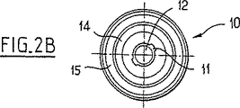
−図2Bは、図2Aの保持用ノブの底面図であり、
−図2Cは、図2Aの蓋の底面図であり、そして
−図3は、図2Aの実施例の一つの変形例の一構成部品の斜視図である。
発明を実施するための最良の形態
最初に、図1A,1Bおよび1Cを参照しながら、本発明の第一実施例を説明する。
本発明に従った蓋1は、保持用ノブ10を含む。当該ノブ10は、継ぎ手手段によって、取り外し自在に固着される。当該継ぎ手手段は、少なくとも一つの突起物11と、一つのノッチ21とを含み、当該ノッチ21内に突起物11が係合する。
図1Cに示される通り、ノッチ21は、突起物11が当該ノッチ21内に入り込むための入口部分21aと、突起物11を当該ノッチ21内に保持するための保持部分21bとを有する。
突起物11は、拡大端11aと、本体11bとを有する。当該拡大端11aは、ノッチ21の入口部分21aを通過することができ、上記本体11bは、上記拡大端11aよりも断面積が小さく、ノッチの保持部分21b内を動くことができる。上記突起物の拡大端11aは、ノッチの保持部分21bを通過することができないので、上記保持用ノブを蓋上に維持する。
この実施例において、固着手段は、同じ二つの突起物11と、対応する二つのノッチ21とを含む。
固着は、蓋1に対して、上記ノブを相対的に回転させることによって達成される。その際、ノッチ21は、共通円上に位置し、当該円の中心は、蓋1の中心である。
上記保持用ノブ10が、自己の中心軸10aの回りに回転させられると、突起物11は、ノッチ21に係合し、それ故、上記保持用ノブは、上記蓋の中心に位置決めされて、当該蓋の重さを更に良好に分布させる。
蓋1は、凹部24を有し、そして、ノブ10は、凹部24に対して実質的に相補的な形状を有する部分14を有し、当該部分14は、上記ノッチ21の上記入口部分21aと上記保持部分21bとの間で、上記凹部24上を動くことができるようにされる。
凹部24は、蓋1の上面に押圧形成されて、円錐台形状を有する。ノブ10は、凹部24に対して相補的な形状の円錐台部分14を有する。
蓋1は更に、肩部25を、円錐台形状の凹部24と、蓋1の残りの部分との間に含む。そして、保持用ノブ10は、相補的な形状の円錐台部分14の回りに環状平坦部15を有する。上記継ぎ手手段11、21は、環状平坦部15と、肩部25とに取り付けられる。
ノブ10が蓋1に取り付けられる際に、ノブ10と蓋1の互いに相補的な形状によって、当該ノブの回転がガイドされる。
上記突起物は、保持用ノブ10の上記環状平坦部15に存在する。
上記ノッチは、上記蓋の肩部25に位置するので、保持用ノブ10が取り外されると、蓋1から突き出るものが全く無くなる。
望ましくは、保持用ノブ10は、更に自己の中心に、蒸気排出孔を含む。そして、望ましくは、蓋1は、対応中央開口22を含み、当該開口22を通して、調理時の蒸気を逃す。
図2A,2Bおよび2Cに示される第二実施例において、上記継ぎ手手段は、保持用ノブ10と蓋1との中心部に位置する。第一実施例のそれと同じ構成部分は、図面において、同じ参照数字で示され、再説明されることはない。
ノブ10は、二つの突起物11を有する。当該突起物11は、その中央垂直軸10aに対して、半径方向に伸びる。
従って、二つの突起物11が存在する。当該突起物11は、ノブ10の端16上に突起物を形成し、望ましくは、相互に反対方向に形成される。
蓋1は、実質的に円形の開口部を含む。当該開口部が形成するものは、ノッチと、各々の入口部分21aと、各々の保持部分21bである。上記入口部分21aは、ノブ10の突起物11を挿入するためのものであって、一つの扇形から構成される。上記保持部分21bは、もう一つ別の扇形から構成され、上記入口部分21aよりも小さな半径を有する。
各々の突起物11は、ノブ10の上記軸線10aからある距離だけ伸びる。当該距離は、入口部分21aによって形成される扇形の半径に実質的に等しく、保持部分21bによって形成される扇形の半径よりも大きい。
この実施例において、上記ノッチは、二つの向かい合う入口部分21aを、二つの向かい合う保持部分21bに隣接させた状態で有する。
上記蓋にノブ10が固着される時、突起物11は、入口部分21aを通過した後、蓋1の下方で、回転させられて、ノッチ21の保持部分21bと同じ高さにされる。
この実施例において、保持用ノブ10は、同じようにして、突起物11を、入口部分21a内に挿入して、蓋1に対して回転させることによって、ノッチ21の保持部分21bの全体に渡って、蓋1の下方で固着される。
蓋のノッチ21の中心部は、開口部22を含む。当該開口部22は、調理時の蒸気を逃し、ノブ10内部の通路12に対応する。当該通路12は、蓋の下方で、自己の端16において開口する。一つの排気孔17がノブに設けられ、当該排気孔17を通して、蒸気が逃される。
図3に示される通り、ノッチ21を、インサート30に形成することができる。当該インサート30は、蓋1の開口部22内に固着され、そして当該蓋よりも厚みを有する。
弾性的な突起物33によって、環状のインサート30を嵌め込むことによって、又は、当該インサート30を糊付けすることによって、又は、当該インサート30を機械的にカールさせることによって、当該環状のインサート30を、蓋内の中央開口部22の縁部に固着することができる。
当該インサート30は、ノッチ21が蓋に直接的に形成されることによって生ずる鋭い縁部の存在を避けることができると共に、当該蓋の厚みについての拘束を取り払う。
当該インサートは、上記ノブを固着する際に上記において説明された通り、二つのノッチ21を有する。当該インサートは、金属またはプラスチック材料から作られる。
インサート30は又一方、別の二つのノッチ34を有する。当該ノッチ34は、上記ノッチ21と同じであり、特に、蓋を収納するために、蓋1の下側に保持用ノブを固着可能にする。
各々のノッチ34は、上記ノッチ21の入口部21aと共通の入口部を有すると共に、当該入口部21aに関して上記ノッチ21の保持部21bとは対称的な位置に配置される保持部を有する。これらのノッチ21a、34の保持部は、上記インサート30の厚さの範囲内で、互いに逆の関係に配置される。即ち、ノッチ21の保持部21bは、インサート30の下部に配置され、そして、ノッチ34の保持部は、インサート30が蓋1に固着される時、当該インサート30の上部に配置される。
ノブ10が蓋1に固着される時に、突起物11は、インサート30の上部から下部に向かって、上記入り口部21aを通過し、次いで、上記保持部21bの下方で旋回させられる。ノブ10が、上記蓋の下側に固着される時、突起物11は、インサート30の下部から上部に向かって、上記入り口部21aを通過し、次いで、ノッチ34の保持部の上方で旋回させられる。
当然のことながら、本発明の範囲を逸脱することなく上記実施例に対して、多くの改変を加えることが可能である。
例えば、上記ノブを、蓋に固着させる際に、当該ノブを、蓋の直線形状のノッチ内に平行移動させることによって固着させることができる。
上記ノブの一つの突起物に、非復帰部材を追加することによって、最初に当該ノブを蓋にロックさせる際に、所定の角度上の閾値をこえた後で、初めて、当該ノブを恒久的に蓋に固着させることができる。
上記ノブ10は、同じくフープまたは握手の形状をも取り得る。TECHNICAL FIELD The present invention relates to a lid for a cooking utensil or the like and having a lid holding knob.
There is already a lid with a hand-held knob that is attached to the lid by means of a background screw. Some of them contain holes for escape of steam.
These holding knobs have disadvantages such as increasing the overall size of the lid and making it difficult to stack the lids together.
In general, the screw is screwed into the central portion of the holding knob, and the steam escape hole is provided in the peripheral portion of the knob. Accordingly, in order to align the steam escape hole of the knob with the steam discharge hole of the lid by screwing the knob into the lid, it is necessary to rotate the knob.
The object of the present invention is to propose a lid that is very simplified in terms of assembly and use and a knob for holding the lid, removing the constraints.
SUMMARY OF THE INVENTION According to the present invention, the lid includes a knob for holding the lid and joint means for fixing the knob to the lid. And a notch. The notch has an inlet portion for allowing the protrusion to enter the notch and a holding portion for holding the protrusion in the notch. When the lid and the knob are moved relative to each other, the protrusion moves between the inlet portion and the holding portion.
Thus, the assembly can be assembled and disassembled simply by moving the knob and lid relative to each other. What is provided by this is a movable holding knob. The movable holding knob has many advantages, that is, the cleaning of the lid is simplified, and the overall bulkiness can be reduced by storing the lids, particularly by stacking the lids.
The lid and the knob form a modular assembly. Here, one holding knob can be used for various different lids regardless of the material and shape of the lid.
In one preferred embodiment of the present invention, the lid has a recess and the knob has a portion having a shape that is substantially complementary to the recess, the portion being the inlet of the notch. It is possible to move on the recess between the part and the holding part. Thus, the complementary shapes of both the lid and the knob guide the knob when the knob is attached to the lid.
This facilitates entry of the projection into the notch and retention of the projection therein.
Desirably, the protrusion is moved between the inlet portion of the notch and the holding portion when the holding knob is rotated about the central axis of the knob.
Although it can be easily removed by the bayonet-type rotary mounting method of the knob to the lid, the user can mount the lid with extremely high reliability when handling the lid with the holding knob.
In another aspect of the invention, a lid retention knob is characterized in that the knob includes a protrusion that is adapted to engage the notch of the lid. is there.
Other features and advantages of the present invention will become more apparent from the following description.
[Brief description of the drawings]
In the accompanying drawings, given by way of example and not intended to limit the invention,
FIG. 1A is a cross-sectional view of a first embodiment of a lid with a holding knob according to the present invention;
-Fig. 1B is a bottom view of the holding knob of Fig. 1A;
FIG. 1C is a plan view of the lid of FIG. 1A;
-Fig. 2A is a cross-sectional view of a second embodiment of a lid with a holding knob according to the invention, partly in elevation,
-Fig. 2B is a bottom view of the holding knob of Fig. 2A;
FIG. 2C is a bottom view of the lid of FIG. 2A, and FIG. 3 is a perspective view of one component of one variation of the embodiment of FIG. 2A.
BEST MODE FOR CARRYING OUT THE INVENTION First, a first embodiment of the present invention will be described with reference to FIGS. 1A, 1B and 1C.
The
As shown in FIG. 1C, the
The
In this embodiment, the fixing means includes the same two
Adherence is achieved by rotating the knob relative to the
When the
The
The
The
When the
The protrusion is present on the annular
Since the notch is located in the
Desirably, the holding
In the second embodiment shown in FIGS. 2A, 2B and 2C, the joint means is located at the center of the holding
The
Accordingly, there are two
The
Each
In this embodiment, the notch has two opposing
When the
In this embodiment, in the same manner, the holding
The central portion of the
As shown in FIG. 3, a
By fitting the
The
The insert has two
The
Each
When the
Naturally, many modifications can be made to the above examples without departing from the scope of the invention.
For example, when the knob is fixed to the lid, the knob can be fixed by translating into the linear notch of the lid.
By adding a non-returning member to one protrusion of the knob, the knob is only permanently locked after the predetermined angular threshold is exceeded when the knob is first locked to the lid. Can be secured to the lid.
The
Claims (10)
前記蓋(1)は、凹部(24)と、前記凹部(24)と前記蓋(1)の残りの部分との間に位置する肩部(25)とを有し、
前記保持用ノブ(10)は、前記凹部(24)と実質的に相補的な形状部分(14)を有すると共に、前記相補的な形状部分(14)の回りに環状平坦部(15)を有し、
前記継ぎ手手段(11、12)は、前記環状平坦部(15)と前記肩部(25)とに取り付けられ、
前記保持用ノブ(10)は、前記ノッチ(21)の前記入口部分(21a)と保持部分(21b)との間で、前記凹部(24)上を動くようにされ、前記保持用ノブ(10)が取り外されると、蓋(1)から突き出るものが全く無くなることを特徴とする蓋。 A retaining knob (10), the retaining knob (10) be composed from projections for fixing to the lid (1) and (11) a notch (21) and the coupling means (11, 21) comprising the notches (21) includes an inlet portion (21a) of said projections (11) passes when entering the notch (21) in, for holding the projection (11) in said notch (21) in and a retaining portion (21b) for, when said knob (10) and the lid (1) is moved relative to each other, said projections (11), wherein the inlet portion of the notch (21) a minute (21a) and the holding portion partial lid moves between (21b) (1),
The lid (1) has a recess (24) and a shoulder (25) located between the recess (24) and the rest of the lid (1);
The holding knob (10) has a shape portion (14) substantially complementary to the recess (24), and an annular flat portion (15) around the complementary shape portion (14). And
The joint means (11, 12) are attached to the annular flat part (15) and the shoulder part (25),
The holding knob (10) is adapted to move on the recess (24) between the inlet portion (21a) and the holding portion (21b) of the notch (21), and the holding knob (10 When the) is removed, nothing protrudes from the lid (1).
前記蓋(1)は、前記継ぎ手手段(11、12)を収容する凹部(24)と、前記凹部(24)と前記蓋(1)の残りの部分との間に位置する肩部(25)とを有し、前記保持用ノブ(10)は、前記凹部(24)と実質的に相補的な形状部分(14)を有し、
前記継ぎ手手段(11、12)は、前記保持用ノブ(10)と蓋(11)の中央部に位置し、
前記保持用ノブ(10)は、前記ノッチ(21)の前記入口部分(21a)と保持部(21b)との間で、前記凹部(24)上を動くようにされ、前記保持用ノブ(10)が取り外されると、蓋(1)から突き出るものが全く無くなることを特徴とする蓋。 And hold knob (10), the retaining knob (10) consisted from the lid protrusion for fixing (1) (11) and notches (21) joint means including a (11, 21) The notch (21) holds the protrusion (11) in the notch (21) and the inlet portion (21a) through which the protrusion (11) passes when entering the notch (21). Holding part (21b) for the projection, and when the knob (10) and the lid (1) are moved relative to each other, the protrusion (11) is inserted into the inlet of the notch (21). A lid (1) moving between a part (21a) and said holding part (21b),
The lid (1) includes a recess (24) for accommodating the joint means (11, 12), and a shoulder (25) positioned between the recess (24) and the remaining portion of the lid (1). The holding knob (10) has a shaped portion (14) substantially complementary to the recess (24);
The joint means (11, 12) is located at the center of the holding knob (10) and the lid (11),
The holding knob (10) is adapted to move on the recess (24) between the inlet portion (21a) and the holding portion (21b) of the notch (21), and the holding knob (10 When the) is removed, nothing protrudes from the lid (1).
Applications Claiming Priority (1)
| Application Number | Priority Date | Filing Date | Title |
|---|---|---|---|
| PCT/FR1996/001934 WO1998024351A1 (en) | 1996-12-04 | 1996-12-04 | Cover with prehensile button |
Publications (2)
| Publication Number | Publication Date |
|---|---|
| JP2001505458A JP2001505458A (en) | 2001-04-24 |
| JP3776460B2 true JP3776460B2 (en) | 2006-05-17 |
Family
ID=9489277
Family Applications (1)
| Application Number | Title | Priority Date | Filing Date |
|---|---|---|---|
| JP52525198A Expired - Fee Related JP3776460B2 (en) | 1996-12-04 | 1996-12-04 | Lid with lid holding knob |
Country Status (7)
| Country | Link |
|---|---|
| US (1) | US6193096B1 (en) |
| EP (1) | EP0942675B1 (en) |
| JP (1) | JP3776460B2 (en) |
| CA (1) | CA2272622C (en) |
| DE (1) | DE69610999T2 (en) |
| ES (1) | ES2153607T3 (en) |
| WO (1) | WO1998024351A1 (en) |
Families Citing this family (6)
| Publication number | Priority date | Publication date | Assignee | Title |
|---|---|---|---|---|
| US7409888B2 (en) * | 2002-12-09 | 2008-08-12 | Bendix Commercial Vehicle Systems, Llc | Cover for parking brake control valve button |
| US8336728B2 (en) * | 2008-04-21 | 2012-12-25 | Rexam Beverage Can Company | Ventable resealing can end closure |
| US8235235B1 (en) | 2008-10-24 | 2012-08-07 | Honda Motor Co., Ltd. | Limit switch cover with magnetic breakaway |
| USD637489S1 (en) | 2010-12-10 | 2011-05-10 | Pactiv Corporation | Pull grip feature of a container lid |
| USD638704S1 (en) | 2010-12-10 | 2011-05-31 | Pactiv Corporation | Container lid |
| ITRM20130198A1 (en) * | 2013-04-03 | 2014-10-04 | Facs S A | APPLIANCE FOR COOKING AND MAINTENANCE IN FOOD OF FOOD. |
Family Cites Families (9)
| Publication number | Priority date | Publication date | Assignee | Title |
|---|---|---|---|---|
| US2733052A (en) * | 1956-01-31 | Closure for mixing vessel | ||
| US1759771A (en) | 1929-02-21 | 1930-05-20 | Otto B Willi | Knob-attaching device |
| US2590395A (en) * | 1949-10-13 | 1952-03-25 | Buckeye Aluminum Company | Cover knob |
| US3278074A (en) * | 1964-11-05 | 1966-10-11 | Yamazaki Masaru | Detachable container handle |
| AT387708B (en) | 1986-03-18 | 1989-03-10 | Meister Alfred | Handle for lids and similar container covers |
| DE9211060U1 (en) * | 1992-08-18 | 1992-12-03 | Synkrona Ag, Stans | Fastening device for a handle element of a cooking or serving dish |
| DE4231360C2 (en) * | 1992-09-18 | 1995-01-19 | Hans Kuehl | Device for releasably attaching a handle to a handle carrier |
| US5584414A (en) * | 1994-10-11 | 1996-12-17 | Res Manufacturing Co. | Thermally-insulating cookware articles |
| US5771783A (en) * | 1995-09-22 | 1998-06-30 | Uss; Tom | Cookware top |
-
1996
- 1996-12-04 EP EP96941697A patent/EP0942675B1/en not_active Expired - Lifetime
- 1996-12-04 JP JP52525198A patent/JP3776460B2/en not_active Expired - Fee Related
- 1996-12-04 WO PCT/FR1996/001934 patent/WO1998024351A1/en active IP Right Grant
- 1996-12-04 DE DE69610999T patent/DE69610999T2/en not_active Expired - Lifetime
- 1996-12-04 ES ES96941697T patent/ES2153607T3/en not_active Expired - Lifetime
- 1996-12-04 CA CA002272622A patent/CA2272622C/en not_active Expired - Fee Related
- 1996-12-04 US US09/308,688 patent/US6193096B1/en not_active Expired - Lifetime
Also Published As
| Publication number | Publication date |
|---|---|
| EP0942675A1 (en) | 1999-09-22 |
| EP0942675B1 (en) | 2000-11-15 |
| JP2001505458A (en) | 2001-04-24 |
| CA2272622A1 (en) | 1998-06-11 |
| DE69610999D1 (en) | 2000-12-21 |
| US6193096B1 (en) | 2001-02-27 |
| ES2153607T3 (en) | 2001-03-01 |
| DE69610999T2 (en) | 2001-03-29 |
| WO1998024351A1 (en) | 1998-06-11 |
| CA2272622C (en) | 2005-11-22 |
Similar Documents
| Publication | Publication Date | Title |
|---|---|---|
| US4291801A (en) | Video cassette storage container | |
| JP3776460B2 (en) | Lid with lid holding knob | |
| JPH10216026A (en) | Handle grip | |
| US20020011494A1 (en) | Splash proof lid assembly | |
| RU2003112674A (en) | ELECTRIC HOUSEHOLD VESSEL FOR COOKING, CLOSED BY A REMOVABLE TURNING COVER | |
| KR20020067552A (en) | A pressure cooker appliance with removable handles | |
| USD400055S (en) | Portable muffin/cupcake pan with dome cover | |
| JP2002031836A (en) | Lens fixture | |
| RU2184473C2 (en) | Cover with handle (versions) | |
| JP2005235994A (en) | Wafer tray | |
| GB2157257A (en) | Handle for a container | |
| JP2008125585A (en) | Fragrance storage vessel | |
| EP0070938A2 (en) | Spinning reel housing with an improved access opening and removable cap | |
| USD390356S (en) | Combined contact lens case and solution dispenser | |
| KR100589274B1 (en) | stopper of glove box | |
| JPH0234647Y2 (en) | ||
| JP2554839Y2 (en) | Drum can lid opening and closing device | |
| WO2019053275A1 (en) | Locking mechanism | |
| JPH0747029Y2 (en) | Waterproof structure of microphone fixing part | |
| US6785062B1 (en) | Ophthalmic self-inspection device | |
| GB2084031A (en) | Connecting sections of a toy racing track | |
| KR200253402Y1 (en) | Bottle cap | |
| JPS6236759Y2 (en) | ||
| TWM642000U (en) | Tab locking assembly structure and cup lid structure | |
| JPH0668167U (en) | Disk adapter |
Legal Events
| Date | Code | Title | Description |
|---|---|---|---|
| A621 | Written request for application examination |
Free format text: JAPANESE INTERMEDIATE CODE: A621 Effective date: 20031201 |
|
| A131 | Notification of reasons for refusal |
Free format text: JAPANESE INTERMEDIATE CODE: A131 Effective date: 20050510 |
|
| A601 | Written request for extension of time |
Free format text: JAPANESE INTERMEDIATE CODE: A601 Effective date: 20050712 |
|
| A602 | Written permission of extension of time |
Free format text: JAPANESE INTERMEDIATE CODE: A602 Effective date: 20050822 |
|
| A521 | Request for written amendment filed |
Free format text: JAPANESE INTERMEDIATE CODE: A523 Effective date: 20051004 |
|
| TRDD | Decision of grant or rejection written | ||
| A01 | Written decision to grant a patent or to grant a registration (utility model) |
Free format text: JAPANESE INTERMEDIATE CODE: A01 Effective date: 20060124 |
|
| A61 | First payment of annual fees (during grant procedure) |
Free format text: JAPANESE INTERMEDIATE CODE: A61 Effective date: 20060223 |
|
| R150 | Certificate of patent or registration of utility model |
Free format text: JAPANESE INTERMEDIATE CODE: R150 |
|
| FPAY | Renewal fee payment (event date is renewal date of database) |
Free format text: PAYMENT UNTIL: 20100303 Year of fee payment: 4 |
|
| FPAY | Renewal fee payment (event date is renewal date of database) |
Free format text: PAYMENT UNTIL: 20110303 Year of fee payment: 5 |
|
| FPAY | Renewal fee payment (event date is renewal date of database) |
Free format text: PAYMENT UNTIL: 20120303 Year of fee payment: 6 |
|
| FPAY | Renewal fee payment (event date is renewal date of database) |
Free format text: PAYMENT UNTIL: 20130303 Year of fee payment: 7 |
|
| FPAY | Renewal fee payment (event date is renewal date of database) |
Free format text: PAYMENT UNTIL: 20130303 Year of fee payment: 7 |
|
| FPAY | Renewal fee payment (event date is renewal date of database) |
Free format text: PAYMENT UNTIL: 20140303 Year of fee payment: 8 |
|
| LAPS | Cancellation because of no payment of annual fees |