JP3775580B2 - Image processing apparatus and method, recording medium, and program - Google Patents
Image processing apparatus and method, recording medium, and program Download PDFInfo
- Publication number
- JP3775580B2 JP3775580B2 JP2001355866A JP2001355866A JP3775580B2 JP 3775580 B2 JP3775580 B2 JP 3775580B2 JP 2001355866 A JP2001355866 A JP 2001355866A JP 2001355866 A JP2001355866 A JP 2001355866A JP 3775580 B2 JP3775580 B2 JP 3775580B2
- Authority
- JP
- Japan
- Prior art keywords
- texture data
- control step
- value
- logarithm
- data corresponding
- Prior art date
- Legal status (The legal status is an assumption and is not a legal conclusion. Google has not performed a legal analysis and makes no representation as to the accuracy of the status listed.)
- Expired - Fee Related
Links
Images


Classifications
-
- G—PHYSICS
- G06—COMPUTING; CALCULATING OR COUNTING
- G06T—IMAGE DATA PROCESSING OR GENERATION, IN GENERAL
- G06T15/00—3D [Three Dimensional] image rendering
- G06T15/04—Texture mapping
-
- G—PHYSICS
- G06—COMPUTING; CALCULATING OR COUNTING
- G06T—IMAGE DATA PROCESSING OR GENERATION, IN GENERAL
- G06T2210/00—Indexing scheme for image generation or computer graphics
- G06T2210/36—Level of detail
Landscapes
- Engineering & Computer Science (AREA)
- Computer Graphics (AREA)
- Physics & Mathematics (AREA)
- General Physics & Mathematics (AREA)
- Theoretical Computer Science (AREA)
- Image Generation (AREA)
Description
【0001】
【発明の属する技術分野】
本発明は、画像処理装置および方法、記録媒体、並びにプログラムに関し、特に、簡単な構成の装置で、lodを算出することができるようにした画像処理装置および方法、記録媒体、並びにプログラムに関する。
【0002】
【従来の技術】
コンピュータグラフィックスにおいて、3次元の図形(モデル)を描画する際に、そのモデルの表面に、あらかじめ用意しておいた2次元画像(以下、テクスチャと称する)を貼り付け、質感の高い画像を生成することができるテクスチャマッピングという手法がある。
【0003】
ここで、テクスチャマッピングの基本的な原理を図1および図2を参照してその概略を説明する。
【0004】
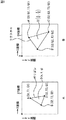
図1AのXY座標は、テクスチャが貼り付けられるモデルが写像される座標である。
【0005】
描画されるモデルは、図1Aに示すような三角形のポリゴンの集合により形成される。モデルを形成する各ポリゴンの頂点A,B,Cには、3次元座標の座標値(Sn,Tn,Qn,但しn=1,2,3)が与えられる。なお、以下において、その図示は省略するが、この3次元の座標をテクスチャ座標と称する。
【0006】
ポリゴンの内部のD点の座標値(s,t,q)は、点A,B,Cのテクスチャ座標値を線形補間して得られる。座標(s,t)は、張り合わせのイメージパターンを示すテクスチャの同次座標(s,t)で、同次項qは、簡単にいうと、拡大縮小率のようなものである。
【0007】
なお、上述した(s,t,q),(Sn,Tn,Qn)などのテクスチャ座標値は、描画するモデルを構成する個々のポリゴンに対して与えられるものであり、変数である。また、テクスチャ座標のポリゴンの頂点座標値(Sn,Tn,Qn,但しn=1,2,3)は、XY座標値(X、Y)に対応し、ポリゴンの内部の画素のテクスチャ座標値(s,t,q)は、XY座標値(x、y)に対応する。
【0008】
図1BのUV座標は、描画するモデルのポリゴンに貼り付けられるテクスチャの2次元座標である。図1Bのテクスチャの点A',B',C',D'のUV座標値(u,v)は、ポリゴンの同次座標(Sn,Tn)を同次項Qで乗算した(Sn/Qn,Tn/Qn)となる。また図1Bのテクスチャは、点A',B',C',D'が、XY座標に写像されたポリゴンの点A,B,C,Dと対応するようにポリゴンに貼り付けられる。
【0009】
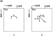
図2Bは、XY座標を構成する単位画素のX軸方向の辺素dx(図2A)がUV座標上では如何なる変位に対応するかを示したもので、XY座標の辺素dxは、UV座標のU軸方向にdu/dx、V軸方向にdv/dxの変位量に対応していることを表している。すなわち、du/dxとdv/dxは、XY座標で(dx)変化したときのUV座標でのuの変位量とvの変化量である。Y軸方向の辺素dy(図示せず)に対応するUV座標上の変位についても同様である。
【0010】
ところで、このテクスチャマッピングを行う際の、高画質を得る手法としてMIPMAPフィルタリング(Multum in parvo mapping )が知られている。MIPMAPフィルタリングについては、Advanced Animation and Rendering Techniques (page.140) 出版社 : ADDISON WESLEYなどに詳しく述べられている。
【0011】
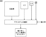
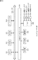
MIPMAPフィルタリングは、図3に示すように、複数の異なる縮小率(図3の例では、1/1、1/2、1/4、1/8)のそれぞれに対応した、複数のフィルタ処理がなされたテクスチャデータ(元画像、1/2画像、1/4画像、1/8画像)を予め用意し、各画素の縮小率に応じた最適なテクスチャデータを選択し使用するものである。すなわち、これにより、イメージの縮小に伴う情報欠落に起因するエイリアシングの影響を抑制でき、高画質を得ることができる。
【0012】
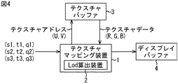
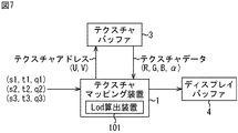
図4は、MIPMAPフィルタリングを行うテクスチャマッピング装置1の利用例を示している。
【0013】
テクスチャバッファ3には、図3に示したような、複数の異なる縮小率のそれぞれに対応した、複数のフィルタ処理がなされたテクスチャデータが記憶されている。
【0014】
テクスチャマッピング装置1は、ポリゴンの画素の縮小率を表すlod(Level Of Detail)を算出する。テクスチャマッピング装置1は、算出したlodに対応する画像をテクスチャバッファ3から読み出し、ディスプレイバッファ4に出力して記憶させる。ディスプレイバッファ4の記録内容に基づく画像が、図示せぬ表示部に表示される。
【0015】
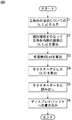
テクスチャマッピング装置1の動作を、図5のフローチャートを参照して説明する。
【0016】
ステップS1において、テクスチャマッピング装置1は、ポリゴン(図1A)の各頂点ついての同次座標および同次項を示す(s1 ,t1 ,q1 )、(s2 ,t2 ,q2)、および(s3 ,t3 ,q3 )を入力する。
【0017】
次に、ステップS2において、テクスチャマッピング装置1は、入力した各頂点の(s1 ,t1 .q1 )、(s2 ,t2 ,q2 )、および(s3 ,t3 ,q3 )を線形補間して、ポリゴンの内部の各画素の同次座標および同次項を示す(s,t,q)を求める。
【0018】
ステップS3において、テクスチャマッピング装置1は、内蔵したlod算出装置2において、ポリゴンの内部の各画素の(s,t,q)から、各画素のlodを算出する。
【0019】
ここでは、式(1)に示すように、2を底とする、各画素の(s,t,q)の縮小率を1/nとした場合のnの対数で表すことができる。従って、縮小率が1/1,1/2,1/4,1/8・・・のとき、0,1,2,3,・・・となる。
【数1】
![]()
縮小率(1/n)のnは、式(2)で求めることができる。
【数2】

なお、式(2)中の、du/dxとdv/dxは、XY座標で(dx)変化したときのUV座標でのuの変位量とvの変化量であり(図2B)、du/dyとdv/dyは、XY座標で(dy)変化したときのUV座標でのuの変位量とvの変化量であり、それらは、式(3)に従って算出される。したがって、nは、式(4)で求めることができる。
【数3】
式(3),(4)中、dS/dx、dT/dx、およびdQ/dxは、X方向の1画素当たりの(S,T,Q)の差分を、dS/dy、dT/dy、およびdQ/dyは、Y方向の1画素当たりの(S,T,Q)の差分を表している。USIZEは、テクスチャの幅(U方向の長さ)を表し、VSIZEは、テクスチャの高さ(V方向の長さ)を表す。
【0023】
従って、lodは、結局、式(1)に式(4)が代入された式(5)が演算されることにより算出される。
【数5】
図6は、式(5)を演算して、lodを算出するlod算出装置2の構成例を表している。
【0025】
除算器11は、入力されたQで、1を除算し(1/Qを演算し)、その除算結果を、乗算器12、乗算器13、回路21(乗算器32,34)、回路22(乗算器42,44)、回路24(乗算器52,54)、および回路25(乗算器62,64)に出力する。
【0026】
乗算器12は、Sと1/Qを乗算し、その乗算結果を、回路21(乗算器35)、および回路22(乗算器45)に出力する。乗算器13は、Tと1/Qを乗算し、その乗算結果を、回路24(乗算器55)、および回路25(乗算器65)に出力する。
【0027】
乗算器31乃至絶対値検出器37からなる回路21は、式(5)の符号Aに対応する部分(以下、部分Aと称する。他の部分についても同様とする)を演算し、乗算器41乃至絶対値検出器47からなる回路22は、式(5)の部分Cを演算し、演算結果を、それぞれ最大値検出器23に出力する。最大値検出器23は、回路21からの値(部分Aの値)と回路22からの値(部分Cの値)のうちの大きい方を検出し、その検出結果を最大値検出器27に出力する。
【0028】
乗算器51乃至絶対値検出器57からなる回路24は、式(5)の部分Bを演算し、乗算器61乃至絶対値検出器67からなる回路25は、部分Dを演算し、演算結果を、それぞれ最大値検出器26に出力する。最大値検出器26は、回路24からの値(部分Bの値)と回路25からの値(部分Dの値)のうちの大きい方を検出し、その検出結果を最大値検出器27に出力する。
【0029】
最大値検出器27は、最大値検出器23からの値と最大値検出器26からの値のうちの大きい方を検出し、その検出結果を対数演算器28に出力する。対数演算器28は、2を底とする最大値検出器27からの値の対数を演算し、その演算結果(式(5)全体の演算結果)を、lodとしてディスプレイバッファ4(図4)に出力する。
【0030】
次に、ステップS4において、テクスチャマッピング装置1は、各画素の(s,t,q)について、sデータをqデータで除算したuデータと、tデータをqデータで除算したvデータとを算出し、テクスチャ座標データ(u,v)を算出する。
【0031】
ステップS5において、テクスチャマッピング装置1は、lod算出装置2で算出したlodと、テクスチャ座標データ(u,v)とから、テクスチャバッファ3における物理アドレスであるテクスチャアドレス(U,V)を求め、テクスチャバッファ3に出力し、テクスチャデータ(R,G,B)を読み出す。
【0032】
次に、ステップS6において、テクスチャマッピング装置1は、ステップS5で読み出しテクスチャデータに所定の処理を施した画素データをディスプレイバッファ4に書き込む。
【0033】
その後、処理は終了する。
【0034】
以上のようにして、テクスチャバッファ3に記憶されている、複数の異なる縮小率のそれぞれに対応した複数のテクスチャデータのうち、lodに対応したテクスチャデータについてのアクセスが実現される。
【0035】
【発明が解決しようとする課題】
ところで、式(5)の部分A乃至部分Dには、Q2の除算が行われる。その結果、lod算出装置2の構成は、図6で示したように、除算器(図6の例の場合、1個の除算器11)の他、多くの乗算器が必要となり(図6の例の場合、22個の乗算器が必要となり)、lod算出装置2の規模が大きくなるの課題があった。
【0036】
本発明はこのような状況に鑑みてなされたものであり、簡単な構成の装置で、lodを算出することができるようにするものである。
【0037】
【課題を解決するための手段】
本発明の画像処理装置は、所定の縮小率に対応した複数のテクスチャデータを記憶する記憶手段と、単位図形の画素の縮小率を、除算を含まない所定の式の演算結果に基づいて決定する決定手段と、決定手段により決定された縮小率に対応するテクスチャデータを、記憶手段から取得する取得手段と、取得手段により取得されたテクスチャデータを単位図形に対応付ける対応付け手段とを備え、決定手段は、式に含まれる2を底とする、任意の値Wの対数の演算を、2を底とする、値Wの浮動小数点の数値である2 e ×mの対数を演算することで行うことを特徴とする。
【0039】
決定手段は、1<m<2において、2を底とする2e×mの対数を、e、(m−1)、およびlog2mとm−1の差分値に基づいて算出することができる。
【0040】
決定手段は、mと、mに対応する差分値からなるテーブルを記憶しており、2を底とする2e×mの対数を、e、(m−1)、およびテーブルにおいてmに対応する差分値に基づいて算出することができる。
【0041】
本発明の画像処理方法は、所定の縮小率に対応した複数のテクスチャデータを記憶する記憶ステップと、単位図形の画素の縮小率を、除算を含まない所定の式の演算結果に基づいて決定する決定ステップと、決定ステップの処理で決定された縮小率に対応するテクスチャデータを、記憶制御ステップの処理で記憶された複数のテクスチャデータから取得する取得ステップと、取得ステップの処理で取得されたテクスチャデータを単位図形に対応付ける対応付けステップとを含み、決定ステップは、式に含まれる2を底とする、任意の値Wの対数の演算を、2を底とする、値Wの浮動小数点の数値である2 e ×mの対数を演算することで行うことを特徴とする。
【0042】
本発明の記録媒体のプログラムは、所定の縮小率に対応した複数のテクスチャデータの記憶を制御する記憶制御ステップと、単位図形の画素の縮小率の、除算を含まない所定の式の演算結果に基づく決定を制御する決定制御ステップと、決定制御ステップの処理で決定された縮小率に対応するテクスチャデータの、記憶制御ステップの処理で記憶された複数のテクスチャデータからの取得を制御する取得制御ステップと、取得制御ステップの処理で取得されたテクスチャデータの、単位図形に対する対応付けを制御する対応付け制御ステップとを含み、決定制御ステップは、式に含まれる2を底とする、任意の値Wの対数の演算を、2を底とする、値Wの浮動小数点の数値である2 e ×mの対数を演算することで行うことを特徴とする。
【0043】
本発明のプログラムは、所定の縮小率に対応した複数のテクスチャデータの記憶を制御する記憶制御ステップと、単位図形の画素の縮小率の、除算を含まない所定の式の演算結果に基づく決定を制御する決定制御ステップと、決定制御ステップの処理で決定された縮小率に対応するテクスチャデータの、記憶制御ステップの処理で記憶された複数のテクスチャデータからの取得を制御する取得制御ステップと、取得制御ステップの処理で取得されたテクスチャデータの単位図形に対する対応付けを制御する対応付け制御ステップとを含み、決定制御ステップは、式に含まれる2を底とする、任意の値Wの対数の演算を、2を底とする、値Wの浮動小数点の数値である2 e ×mの対数を演算することで行うを処理をコンピュータに実行させることを特徴とする。
【0044】
本発明の画像処理装置および方法、並びにプログラムにおいては、所定の縮小率に対応した複数のテクスチャデータが記憶され、単位図形の画素の縮小率が、除算を含まない所定の式の演算結果に基づいて決定され、決定された縮小率に対応するテクスチャデータが、記憶された複数のテクスチャデータから取得され、取得されたテクスチャデータが単位図形に対応付けられ、単位図形の画素の縮小率の決定は、式に含まれる2を底とする、任意の値Wの対数の演算が、2を底とする、値Wの浮動小数点の数値である2 e ×mの対数を演算することで行われる。
【0045】
【発明の実施の形態】
図7は、本発明を適用したテクスチャマッピング装置1の利用例を示している。このテクスチャマッピング装置1には、図4のlod算出装置2に代えて、lod算出装置101が設けられている。
【0046】
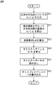
次に、このテクスチャマッピング装置1の動作を、図8のフローチャートを参照して説明する。
【0047】
ステップS11,S12、およびステップS14乃至ステップS16においては、図5のステップS1,S2、およびステップS4乃至ステップS6における場合と同様の処理が実行されるので、その説明は省略する。
【0048】
ステップS13において、lod算出装置101は、ポリゴンの内部の各画素の(s,t,q)から、式(6)を演算して、lodを算出する。
【数6】
式(6)は、図4のlod算出装置2において、lodを算出するために演算された式(5)が、除算を含まないように展開されたもので、正確には、式(5)を式(7)のように展開した後、さらに式(6)のように展開したものである。
【数7】
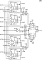
図9は、lod算出装置101の構成例を表している。このlod算出装置101には、乗算器が、図4のlod算出装置2には、22個設けられていたのに対して、9個しか存在せず、装置の小型化が図られている。
【0051】
図9の回路111A乃至111Cのそれぞれは、2個の乗算器、1個の減算器、および1個の絶対値検出器から構成されている。
【0052】
乗算器121−1乃至絶対値検出器121−4からなる回路111Aは、式(6)の部分Aを演算し、その演算結果を、最大値検出器111Cに出力する。すなわち、乗算器121−1は、dS/dxとQを乗算し、乗算器121−2は、dQ/dxとSを乗算し、その乗算結果を、それぞれ減算器121−3に出力する。減算器121−3は、乗算器121−1からの乗算結果から、乗算器121−2からの乗算結果を減算して、その減算結果を、絶対値検出器121−4に出力する。絶対値検出器121−4は、減算器121−3からの減算結果の絶対値を検出し、その検出結果を、最大値検出器111Cに出力する。
【0053】
乗算器122−1乃至絶対値検出器122−4からなる回路111Bは、式(6)の部分Bを演算し、その演算結果を最大値検出器111Cに出力する。
【0054】
最大値検出器111Cは、回路111Aからの演算結果(式(6)の部分Aの値)と、回路111Bからの演算結果(式(6)の部分Bの値)のうちの大きい方を検出し、対数演算器111Dに出力する。すなわち、最大値検出器111Cは、式(6)の部分Cを演算する。
【0055】
対数演算器111Dは、2を底とする最大値検出器111Cからの値の対数を演算し(式(6)の部分Dを演算し)、その演算結果を、加算器131に出力する。
【0056】
対数演算器111Eは、2を底とするUSIZEの対数を演算し(式(6)の部分Eを演算し)、その演算結果を、減算器132に出力する。
【0057】
乗算器111Fは、Qの二乗を演算し(式(6)の部分Fを演算し)、その演算結果を、対数演算器111Gに出力する。対数演算器111Gは、2を底とするQの二乗の対数を演算し(部分Gを演算し)、その演算結果を、減算器132および減算器133に出力する。
【0058】
対数演算器111Hは、2を底とするVSIZEの対数を演算し(式(6)の部分Hを演算し)、その演算結果を、減算器133に出力する。
【0059】
乗算器123−1乃至絶対値検出器123−4からなる回路111Iは、式(6)の部分Iを演算し、乗算器124−1乃至絶対値検出器124−4からなる回路111Jは、部分Jを演算し、その演算結果を、それぞれ最大値検出器111Kに出力する。
【0060】
最大値検出器111Kは、回路111Iからの演算結果(式(6)の部分Iの値)と、回路111Jからの演算結果(式(6)の部分Jの値)のうちの大きい方を検出し(部分Kを演算し)、対数演算器111Lに出力する。対数演算器111Lは、2を底とする最大値検出器111Kからの値の対数を演算し(部分Lを演算し)、その演算結果を、加算器134に出力する。
【0061】
減算器132は、対数演算器111Eからの値から、対数演算器111Gからの値を減算して、その減算結果を、加算器131に出力する。加算器131は、対数演算器111Dからの値と減算器132からの値を加算して、その加算結果を、最大値検出器135に出力する。
【0062】
減算器133は、対数演算器111Hからの値から対数演算器111Gからの値を減算し、その減算結果を、加算器134に出力する。
【0063】
加算器134は、対数演算器111Lからの値と、減算器133からの値とを加算し、その加算結果を、最大値検出器135に出力する。
【0064】
最大値検出器135は、加算器131からの値と、加算器134からの値のうちの大きい方を検出し、その検出結果(式(6)全体の演算結果)を、lodとして、ディスプレイバッファ4に出力する。
【0065】
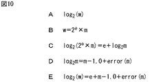
ところで、対数演算器111D,E,G,H,Lは、図10Aの式に示すように、2を底とする、入力された値(以下、値Wと称する)の対数を演算するが、lod算出装置101への入力値は、浮動小数の数値であるので、ここでは浮動小数点の数値の対数演算が行われる。
【0066】
以下に、この浮動小数点の数値の対数演算について説明する。
【0067】
値Wの浮動小数点の数値は、図10Bに示すように表現され、それの、図10Cの左辺のように、2を底とする対数をとると、図10Cの右辺が得られる。
【0068】
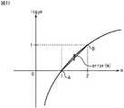
ところで、図10Cの右辺の第2項(log2m)の軌跡は、図11に示すようになる。すなわち、図10Cの右辺の第2項は、1<m<2の範囲において、図11中、点Aと点Bを通る直線に近似することができるので、図10Dの式が成り立つ。
【0069】
図10Dの式中のerror(m)は、図10Cの右辺の第2項と、図11の点Aと点Bを通る直線との差分である(log2mと(m−1.0)の差分である)。
【0070】
すなわち、対数演算器は、1<m<2においては、値Wの浮動小数点の数値を構成するeとm、並びにmに対応するerror(m)を得て、図10Dを図10Cの右辺に代入することで(結局、図10Eの右辺を演算することで)、図10Aの対数の値を得ることができる。
【0071】
なお、error(m)(図10D,Eの式、図11)は、mに1対1に対応するので、この例の場合、対数演算器は、mとerror(m)とが1体1に対応付けられた対応テーブル(詳細は後述するが、正確には、m-1とerror(m)とが1体1に対応付けられた対応テーブル)を記憶しているものとし、値Wのmに対応するerror(m)をその対応テーブルから取得するものとする。
【0072】
また、ここでの、e、(m−1.0)、およびerror(m)の加算(図10Eの右辺の演算)は、eは、整数であり、(m−1.0)+error(m)は、1<m<2の下では、少数点以下の値となるので、この例の場合、図12に示すように、eを4ビットで表して整数部に設定し、(m−1.0+error(m))を4ビットで表して小数部に設定することで行われる。すなわち、lodは、4ビットの整数部と4ビットの小数部からなる。
【0073】
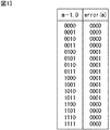
また、(m−1.0)とerror(m)の加算は、m−1.0を表す4ビットと、error(m)を表す4ビットを加算することで行われる。すなわち、この例の場合、対応テーブルには、図13に示すように、小数点以下の数値としての(m−1.0)を表す4ビットと、それに対応する小数点以下の数値としてのerror(m)を表す4ビットが対応して設定されている。m−1.0が0または1、すなわち、mが1または2に近い値であればあるほど、図11に示すように、error(m)は小さいものとなっている。
【0074】
例えば、m−1.0が、値0.5であるとき(m=1.5であるとき)、m−1.0を表す4ビットは”1000”であるので、その”1000”と、対応テーブルにおいてm−1.0の欄の”1000”に対応して設定されているerror(m)の欄の”0001”とが加算され、その加算結果である”1001”が小数部となる。
【0075】
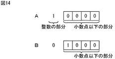
なお、値1を、図14Aに示すように、整数を表す1ビットと、小数点以下の数値を表す4ビットで表した場合、値0.5は、図14Bのように、図14Aの整数を表す1ビットに設定された1を、図中右方向に1ビット分シフトしたものとなるので(1を1/2したものであるので)、値0.5は、”1000”となる。
【0076】
上述した一連の処理は、ハードウエアにより実現させることもできるが、ソフトウエアにより実現させることもできる。一連の処理をソフトウエアにより実現する場合には、そのソフトウエアを構成するプログラムがコンピュータにインストールされ、そのプログラムがコンピュータで実行されることより、上述したlod算出装置101が機能的に実現される。
【0077】
図15は、上述のようなlod算出装置101として機能するコンピュータ501の一実施の形態の構成を示すブロック図である。CPU(Central Processing Unit)511にはバス515を介して入出力インタフェース516が接続されており、CPU511は、入出力インタフェース516を介して、ユーザから、キーボード、マウスなどよりなる入力部518から指令が入力されると、例えば、ROM(Read Only Memory)512、ハードディスク514、またはドライブ520に装着される磁気ディスク531、光ディスク532、光磁気ディスク533、若しくは半導体メモリ534などの記録媒体に格納されているプログラムを、RAM(Random Access Memory)513にロードして実行する。これにより、上述した各種の処理が行われる。さらに、CPU511は、その処理結果を、例えば、入出力インタフェース516を介して、LCD(Liquid Crystal Display)などよりなる出力部517に必要に応じて出力する。なお、プログラムは、ハードディスク514やROM512に予め記憶しておき、コンピュータ501と一体的にユーザに提供したり、磁気ディスク531、光ディスク532、光磁気ディスク533,半導体メモリ534等のパッケージメディアとして提供したり、衛星、ネットワーク等から通信部519を介してハードディスク514に提供することができる。
【0078】
なお、本明細書において、記録媒体により提供されるプログラムを記述するステップは、記載された順序に沿って時系列的に行われる処理はもちろん、必ずしも時系列的に処理されなくとも、並列的あるいは個別に実行される処理をも含むものである。
【0079】
また、本明細書において、システムとは、複数の装置により構成される装置全体を表すものである。
【0080】
【発明の効果】
本発明によれば、装置を簡単な構成にすることができる。
【図面の簡単な説明】
【図1】テクスチャマッピングの原理を説明する図である。
【図2】テクスチャマッピングの原理を説明する他の図である。
【図3】 MIPMAPフィルタリングの原理を説明する図である。
【図4】従来のテクスチャマッピング装置の構成例を示すブロック図である。
【図5】図4のテクスチャマッピング装置の動作を説明するフローチャートである。
【図6】図4のlod算出装置2の構成例を示すブロック図である。
【図7】本発明を適用したテクスチャマッピング装置の構成例を示すブロック図である。
【図8】図7のテクスチャマッピング装置の動作を説明するフローチャートである。
【図9】図7のlod算出装置の構成例を示すブロック図である。
【図10】図7のlod算出装置におけるlod算出方法について説明する図である。
【図11】 log2mとmの関係を示す図である。
【図12】 lodのデータ構成を説明する図である。
【図13】対応テーブルを説明する図である。
【図14】小数部を説明する図である。
【図15】パーソナルコンピュータ501の構成例を示すブロック図である。
【符号の説明】
1 テクスチャマッピング装置, 3 テクスチャバッファ, 4 ディスプレイバッファ, 101 lod算出装置, 111A 回路, 111B 回路, 111C 最大値検出器, 111D 対数演算器, 111E 対数演算器, 111F 乗算器, 111G 対数演算器, 111H 対数演算器,111I 回路, 111J 回路, 111K 最大値検出器, 111L対数演算器, 131 加算器, 132 減算器, 133 減算器, 134 加算器, 135 最大値検出器[0001]
BACKGROUND OF THE INVENTION
The present invention relates to an image processing apparatus and method, a recording medium, and a program, and more particularly, to an image processing apparatus and method, a recording medium, and a program that can calculate lod with a simple configuration apparatus.
[0002]
[Prior art]
In computer graphics, when drawing a three-dimensional figure (model), a two-dimensional image (hereinafter referred to as texture) prepared in advance is pasted on the surface of the model to generate a high-quality image. There is a technique called texture mapping that can be done.
[0003]
Here, the basic principle of texture mapping will be outlined with reference to FIGS.
[0004]
The XY coordinates in FIG. 1A are coordinates to which the model to which the texture is attached is mapped.
[0005]
The model to be drawn is formed by a set of triangular polygons as shown in FIG. 1A. Three-dimensional coordinate values (Sn, Tn, Qn, where n = 1, 2, 3) are given to the vertices A, B, and C of each polygon forming the model. In the following, although not shown, the three-dimensional coordinates are referred to as texture coordinates.
[0006]
The coordinate value (s, t, q) of point D inside the polygon is obtained by linearly interpolating the texture coordinate values of points A, B, and C. The coordinates (s, t) are the homogeneous coordinates (s, t) of the texture indicating the image pattern of pasting, and the homogeneous term q is simply like an enlargement / reduction ratio.
[0007]
The texture coordinate values such as (s, t, q) and (Sn, Tn, Qn) described above are given to the individual polygons constituting the model to be drawn and are variables. In addition, the vertex coordinate values (Sn, Tn, Qn, where n = 1, 2, 3) of the texture coordinate polygon correspond to the XY coordinate values (X, Y), and the texture coordinate value ( s, t, q) corresponds to XY coordinate values (x, y).
[0008]
The UV coordinates in FIG. 1B are the two-dimensional coordinates of the texture pasted on the polygon of the model to be drawn. The UV coordinate values (u, v) of the texture points A ′, B ′, C ′, D ′ in FIG. 1B are multiplied by the homogeneous coordinates Q of the polygons (Sn, Tn) (Sn / Qn, Tn / Qn). 1B is pasted on the polygon so that the points A ′, B ′, C ′, D ′ correspond to the points A, B, C, D of the polygon mapped to the XY coordinates.
[0009]
FIG. 2B shows how the side element dx in the X-axis direction (FIG. 2A) of the unit pixel constituting the XY coordinate corresponds to the UV coordinate, and the side element dx of the XY coordinate indicates the UV coordinate. This corresponds to a displacement amount of du / dx in the U-axis direction and dv / dx in the V-axis direction. That is, du / dx and dv / dx are the amount of displacement of u and the amount of change of v in the UV coordinates when (dx) changes in the XY coordinates. The same applies to the displacement on the UV coordinate corresponding to the side element dy (not shown) in the Y-axis direction.
[0010]
Incidentally, MIPMAP filtering (Multum in parvo mapping) is known as a technique for obtaining high image quality when performing this texture mapping. MIPMAP filtering is described in detail in Advanced Animation and Rendering Techniques (page 140) Publisher: ADDISON WESLEY.
[0011]
As shown in FIG. 3, the MIPMAP filtering includes a plurality of filter processes corresponding to each of a plurality of different reduction ratios (1/1, 1/2, 1/4, 1/8 in the example of FIG. 3). Prepared texture data (original image, 1/2 image, 1/4 image, 1/8 image) is prepared in advance, and optimum texture data corresponding to the reduction ratio of each pixel is selected and used. That is, it is possible to suppress the influence of aliasing due to information loss accompanying image reduction, and to obtain high image quality.
[0012]
FIG. 4 shows a usage example of the
[0013]
The texture buffer 3 stores texture data subjected to a plurality of filter processes corresponding to a plurality of different reduction ratios as shown in FIG.
[0014]
The
[0015]
The operation of the
[0016]
In step S1, the
[0017]
Next, in step S2, the
[0018]
In step S <b> 3, the
[0019]
Here, as shown in Expression (1), it can be expressed by the logarithm of n when the reduction rate of (s, t, q) of each pixel is 1 / n with 2 as the base. Therefore, when the reduction ratio is 1/1, 1/2, 1/4, 1/8..., 0, 1, 2, 3,.
[Expression 1]
![]()
N of the reduction ratio (1 / n) can be obtained by Expression (2).
[Expression 2]
In the equation (2), du / dx and dv / dx are the amount of displacement of u and the amount of change of v in the UV coordinates when (dx) changes in the XY coordinates (FIG. 2B), and du / dy and dv / dy are the amount of displacement of u and the amount of change of v in the UV coordinates when (dy) changes in the XY coordinates, and are calculated according to Equation (3). Therefore, n can be obtained by Expression (4).
[Equation 3]
In equations (3) and (4), dS / dx, dT / dx, and dQ / dx are the differences in (S, T, Q) per pixel in the X direction, dS / dy, dT / dy, And dQ / dy represent the difference of (S, T, Q) per pixel in the Y direction. USIZE represents the width of the texture (length in the U direction), and VSIZE represents the height of the texture (length in the V direction).
[0023]
Therefore, lod is finally calculated by calculating Expression (5) in which Expression (4) is substituted into Expression (1).
[Equation 5]
FIG. 6 illustrates a configuration example of the
[0025]
The divider 11
[0026]
The
[0027]
The
[0028]
The
[0029]
The
[0030]
Next, in step S4, the
[0031]
In step S5, the
[0032]
Next, in step S <b> 6, the
[0033]
Thereafter, the process ends.
[0034]
As described above, the access to the texture data corresponding to the lod among the plurality of texture data corresponding to each of the plurality of different reduction ratios stored in the texture buffer 3 is realized.
[0035]
[Problems to be solved by the invention]
By the way, the part A to the part D of the formula (5) include Q2Is divided. As a result, the configuration of the
[0036]
The present invention has been made in view of such a situation, and makes it possible to calculate lod with an apparatus having a simple configuration.
[0037]
[Means for Solving the Problems]
The image processing apparatus according to the present invention determines a storage unit that stores a plurality of texture data corresponding to a predetermined reduction ratio, and a reduction ratio of a pixel of a unit graphic based on a calculation result of a predetermined expression that does not include division. A determination unit, an acquisition unit for acquiring texture data corresponding to the reduction ratio determined by the determination unit from the storage unit, and an association unit for associating the texture data acquired by the acquisition unit with a unit graphic;The determination means is a floating-
[0039]
The determination means is 2 with 2 as the base when 1 <m <2.eThe logarithm of xm, e, (m−1), and log2It can be calculated based on the difference value between m and m-1.
[0040]
The determining means stores a table made up of m and a difference value corresponding to m, with 2 being the
[0041]
According to the image processing method of the present invention, a storage step for storing a plurality of texture data corresponding to a predetermined reduction ratio and a reduction ratio of a pixel of a unit graphic are determined based on a calculation result of a predetermined expression not including division. A determination step, an acquisition step of acquiring texture data corresponding to the reduction ratio determined in the processing of the determination step from a plurality of texture data stored in the processing of the storage control step, and a texture acquired in the processing of the acquisition step An association step of associating data with the unit figure,The decision step is a logarithmic operation of an arbitrary value W with 2 as a base included in the formula, and is a floating-
[0042]
The recording medium program according to the present invention includes a storage control step for controlling storage of a plurality of texture data corresponding to a predetermined reduction ratio, and a calculation result of a predetermined expression that does not include division of the pixel figure reduction ratio. A determination control step for controlling the determination based on, and an acquisition control step for controlling the acquisition of the texture data corresponding to the reduction ratio determined in the processing of the determination control step from the plurality of texture data stored in the processing of the storage control step And an association control step for controlling the association of the texture data acquired in the acquisition control step with the unit graphic,The decision control step is a logarithmic operation of an arbitrary value W, with 2 as a base included in the expression, and is a floating-
[0043]
The program of the present invention determines a storage control step for controlling storage of a plurality of texture data corresponding to a predetermined reduction ratio, and determines a reduction ratio of a pixel of a unit graphic based on a calculation result of a predetermined expression not including division. A determination control step for controlling, an acquisition control step for controlling acquisition of the texture data corresponding to the reduction ratio determined in the processing of the determination control step from a plurality of texture data stored in the processing of the storage control step, and acquisition An association control step for controlling the association of the texture data acquired in the process of the control step with the unit graphic,The decision control step is a logarithmic operation of an arbitrary value W, with 2 as a base included in the expression, and is a floating-
[0044]
In the image processing apparatus, method, and program of the present invention, a plurality of texture data corresponding to a predetermined reduction ratio is stored, and the reduction ratio of the pixel of the unit graphic is based on a calculation result of a predetermined expression not including division. Texture data corresponding to the determined reduction ratio is acquired from the plurality of stored texture data, the acquired texture data is associated with the unit graphic,Determination of the reduction ratio of the pixel of the unit graphic is a floating point value of the value W, where the logarithm operation of an arbitrary value W with 2 as the base included in the equation is 2 e This is done by calculating the logarithm of × m.
[0045]
DETAILED DESCRIPTION OF THE INVENTION
FIG. 7 shows an example of use of the
[0046]
Next, the operation of the
[0047]
In steps S11 and S12 and steps S14 to S16, the same processes as those in steps S1 and S2 and steps S4 to S6 of FIG.
[0048]
In step S <b> 13, the
[Formula 6]
Expression (6) is an expression (5) calculated to calculate lod in the
[Expression 7]
FIG. 9 illustrates a configuration example of the
[0051]
Each of the
[0052]
The
[0053]
A
[0054]
The maximum value detector 111C detects the larger of the calculation result from the
[0055]
The logarithmic calculator 111D calculates the logarithm of the value from the maximum value detector 111C with 2 as the base (calculates the part D of the equation (6)), and outputs the calculation result to the
[0056]
The
[0057]
[0058]
The
[0059]
The circuit 111I composed of the multiplier 123-1 to the absolute value detector 123-4 calculates the part I of the equation (6), and the
[0060]
The
[0061]
The
[0062]
The
[0063]
The
[0064]
The
[0065]
By the way, the logarithmic calculators 111D, E, G, H, and L calculate the logarithm of the input value (hereinafter referred to as the value W) with 2 as the base, as shown in the equation of FIG. 10A. Since the input value to the
[0066]
In the following, the logarithmic operation of this floating point number will be described.
[0067]
The floating point value of the value W is expressed as shown in FIG. 10B, and the right side of FIG. 10C is obtained by taking the logarithm with 2 as the base, as in the left side of FIG. 10C.
[0068]
By the way, the second term on the right side of FIG.2The trajectory of m) is as shown in FIG. That is, the second term on the right side of FIG. 10C can be approximated to a straight line passing through point A and point B in FIG. 11 within the range of 1 <m <2, and therefore the equation of FIG. 10D is established.
[0069]
Error (m) in the equation of FIG. 10D is the difference between the second term on the right side of FIG. 10C and the straight line passing through points A and B in FIG.2m is the difference between (m−1.0)).
[0070]
That is, when 1 <m <2, the logarithm calculator obtains e and m that constitute the floating-point value of the value W, and error (m) corresponding to m, and FIG. 10D is displayed on the right side of FIG. 10C. By substituting (after all, the right side of FIG. 10E is calculated), the logarithmic value of FIG. 10A can be obtained.
[0071]
Note that error (m) (the equations in FIGS. 10D and 10E, FIG. 11) corresponds to m on a one-to-one basis. Therefore, in this example, the logarithmic calculator has one m and error (m). Is stored in a correspondence table (details will be described later, to be precise, a correspondence table in which m-1 and error (m) are associated with one body 1). It is assumed that error (m) corresponding to m is acquired from the correspondence table.
[0072]
In addition, in the addition of e, (m−1.0), and error (m) (the calculation on the right side of FIG. 10E), e is an integer, and (m−1.0) + error (m) is 1 Since the value is less than the decimal point under <m <2, in this example, as shown in FIG. 12, e is represented by 4 bits and set to the integer part, and (m−1.0 + error (m) ) Is represented by 4 bits and set to the decimal part. That is, lod consists of a 4-bit integer part and a 4-bit decimal part.
[0073]
The addition of (m-1.0) and error (m) is performed by adding 4 bits representing m-1.0 and 4 bits representing error (m). That is, in this example, as shown in FIG. 13, the correspondence table includes 4 bits representing (m−1.0) as a numerical value after the decimal point and error (m) as a numerical value corresponding to the decimal point. The corresponding 4 bits are set. As m-1.0 is 0 or 1, that is, m is a value closer to 1 or 2, error (m) is smaller as shown in FIG.
[0074]
For example, when m-1.0 is a value of 0.5 (when m = 1.5), since the 4 bits representing m-1.0 are “1000”, “1000” is represented by m in the correspondence table. “0001” in the column of error (m) set corresponding to “1000” in the column of −1.0 is added, and “1001” which is the addition result becomes a decimal part.
[0075]
When the
[0076]
The series of processes described above can be realized by hardware, but can also be realized by software. When the series of processing is realized by software, a program constituting the software is installed in a computer, and the program is executed by the computer, so that the above-described
[0077]
FIG. 15 is a block diagram illustrating a configuration of an embodiment of a computer 501 that functions as the
[0078]
In the present specification, the step of describing the program provided by the recording medium is not limited to the processing performed in chronological order according to the described order, but is not necessarily performed in chronological order. It also includes processes that are executed individually.
[0079]
Further, in this specification, the system represents the entire apparatus constituted by a plurality of apparatuses.
[0080]
【The invention's effect】
According to the present invention,The apparatus can have a simple configuration.
[Brief description of the drawings]
FIG. 1 is a diagram for explaining the principle of texture mapping.
FIG. 2 is another diagram illustrating the principle of texture mapping.
FIG. 3 is a diagram illustrating the principle of MIPMAP filtering.
FIG. 4 is a block diagram illustrating a configuration example of a conventional texture mapping apparatus.
FIG. 5 is a flowchart for explaining the operation of the texture mapping apparatus of FIG. 4;
6 is a block diagram illustrating a configuration example of a
FIG. 7 is a block diagram illustrating a configuration example of a texture mapping apparatus to which the present invention is applied.
FIG. 8 is a flowchart for explaining the operation of the texture mapping apparatus in FIG. 7;
9 is a block diagram illustrating a configuration example of the lod calculation device in FIG. 7;
10 is a diagram for explaining a lod calculation method in the lod calculation apparatus of FIG. 7;
FIG. 11 log2It is a figure which shows the relationship between m and m.
FIG. 12 is a diagram illustrating a data configuration of lod.
FIG. 13 is a diagram for explaining a correspondence table;
FIG. 14 is a diagram illustrating a decimal part.
15 is a block diagram illustrating a configuration example of a personal computer 501. FIG.
[Explanation of symbols]
1 texture mapping device, 3 texture buffer, 4 display buffer, 101 lod calculation device, 111A circuit, 111B circuit, 111C maximum value detector, 111D logarithmic calculator, 111E logarithmic calculator, 111F multiplier, 111G logarithmic calculator, 111H Logarithmic calculator, 111I circuit, 111J circuit, 111K maximum value detector, 111L logarithmic calculator, 131 adder, 132 subtractor, 133 subtractor, 134 adder, 135 maximum value detector
Claims (6)
所定の縮小率に対応した複数のテクスチャデータを記憶する記憶手段と、
前記単位図形の画素の縮小率を、除算を含まない所定の式の演算結果に基づいて決定する決定手段と、
前記決定手段により決定された前記縮小率に対応する前記テクスチャデータを、前記記憶手段から取得する取得手段と、
前記取得手段により取得された前記テクスチャデータを前記単位図形に対応付ける対応付け手段と
を備え、
前記決定手段は、前記式に含まれる2を底とする、任意の値Wの対数の演算を、2を底とする、前記値Wの浮動小数点の数値である2 e ×mの対数を演算することで行う
ことを特徴とする画像処理装置。In an image processing apparatus for determining a reduction rate for each pixel of a plurality of unit graphics forming a model, and associating texture data corresponding to the determined reduction rate with the unit graphic,
Storage means for storing a plurality of texture data corresponding to a predetermined reduction ratio;
Determining means for determining a reduction rate of the pixel of the unit graphic based on a calculation result of a predetermined expression not including division;
Obtaining means for obtaining the texture data corresponding to the reduction ratio determined by the determining means from the storage means;
Association means for associating the texture data acquired by the acquisition means with the unit graphic;
The determining means calculates a logarithm of an arbitrary value W with 2 as a base included in the formula, and calculates a logarithm of 2 e × m that is a floating point value of the value W with a base of 2. An image processing apparatus characterized in that the processing is performed .
ことを特徴とする請求項1に記載の画像処理装置。The determining means calculates the logarithm of 2 e × m with 2 as the base when 1 <m <2, based on e, (m−1), and a difference value between log 2 m and m−1. The image processing apparatus according to claim 1.
ことを特徴とする請求項1に記載の画像処理装置。The determining means stores a table including m and the difference value corresponding to m, and the logarithm of 2 e × m with 2 as a base is expressed as e, the (m−1), and the The image processing apparatus according to claim 1, wherein calculation is performed based on the difference value corresponding to the m in the table.
所定の縮小率に対応した複数のテクスチャデータを記憶する記憶ステップと、
前記単位図形の画素の縮小率を、除算を含まない所定の式の演算結果に基づいて決定する決定ステップと、
前記決定ステップの処理で決定された前記縮小率に対応する前記テクスチャデータを、前記記憶制御ステップの処理で記憶された前記複数のテクスチャデータから取得する取得ステップと、
前記取得ステップの処理で取得された前記テクスチャデータを前記単位図形に対応付ける対応付けステップと
を含み、
前記決定ステップは、前記式に含まれる2を底とする、任意の値Wの対数の演算を、2を底とする、前記値Wの浮動小数点の数値である2 e ×mの対数を演算することで行う
ことを特徴とする画像処理方法。In the image processing method of the image processing apparatus for determining a reduction rate for each pixel of a plurality of unit graphics forming a model, and associating texture data corresponding to the determined reduction rate with the unit graphic,
A storage step of storing a plurality of texture data corresponding to a predetermined reduction ratio;
A determination step of determining a reduction rate of the pixel of the unit graphic based on a calculation result of a predetermined expression not including division;
An acquisition step of acquiring the texture data corresponding to the reduction ratio determined in the processing of the determination step from the plurality of texture data stored in the processing of the storage control step;
Associating the texture data acquired in the processing of the acquisition step with the unit graphic; and
The determination step calculates a logarithm of an arbitrary value W with 2 as a base included in the formula, and calculates a logarithm of 2 e × m that is a floating point value of the value W with 2 as a base. An image processing method characterized by being performed .
所定の縮小率に対応した複数のテクスチャデータの記憶を制御する記憶制御ステップと、
前記単位図形の画素の縮小率の、除算を含まない所定の式の演算結果に基づく決定を制御する決定制御ステップと、
前記決定制御ステップの処理で決定された前記縮小率に対応する前記テクスチャデータの、前記記憶制御ステップの処理で記憶された前記複数のテクスチャデータからの取得を制御する取得制御ステップと、
前記取得制御ステップの処理で取得された前記テクスチャデータの、前記単位図形に対する対応付けを制御する対応付け制御ステップと
を含み、
前記決定制御ステップは、前記式に含まれる2を底とする、任意の値Wの対数の演算を、2を底とする、前記値Wの浮動小数点の数値である2 e ×mの対数を演算することで行う
ことを特徴とするコンピュータが読み取り可能なプログラムが記録されている記録媒体。A program for an image processing apparatus that determines a reduction rate for each pixel of a plurality of unit graphics forming a model, and associates texture data corresponding to the determined reduction rate with the unit graphic,
A storage control step for controlling storage of a plurality of texture data corresponding to a predetermined reduction ratio;
A determination control step for controlling determination of a reduction ratio of the pixel of the unit graphic based on a calculation result of a predetermined expression not including division;
An acquisition control step for controlling acquisition of the texture data corresponding to the reduction ratio determined in the determination control step processing from the plurality of texture data stored in the storage control step processing;
An association control step for controlling the association of the texture data acquired in the acquisition control step with the unit graphic;
The determination control step calculates a logarithm of an arbitrary value W with 2 as a base included in the formula, and calculates a logarithm of 2 e × m that is a floating point value of the value W with 2 as a base. recording medium from which a computer readable program which is characterized in that by calculating is recorded.
所定の縮小率に対応した複数のテクスチャデータの記憶を制御する記憶制御ステップと、
前記単位図形の画素の縮小率の、除算を含まない所定の式の演算結果に基づく決定を制御する決定制御ステップと、
前記決定制御ステップの処理で決定された前記縮小率に対応する前記テクスチャデータの、前記記憶制御ステップの処理で記憶された前記複数のテクスチャデータからの取得を制御する取得制御ステップと、
前記取得制御ステップの処理で取得された前記テクスチャデータの前記単位図形に対する対応付けを制御する対応付け制御ステップと
を含み、
前記決定制御ステップは、前記式に含まれる2を底とする、任意の値Wの対数の演算を、2を底とする、前記値Wの浮動小数点の数値である2 e ×mの対数を演算することで行う
を処理をコンピュータに実行させることを特徴とするプログラム。A program for an image processing apparatus that determines a reduction rate for each pixel of a plurality of unit graphics forming a model, and associates texture data corresponding to the determined reduction rate with the unit graphic,
A storage control step for controlling storage of a plurality of texture data corresponding to a predetermined reduction ratio;
A determination control step for controlling determination of a reduction ratio of the pixel of the unit graphic based on a calculation result of a predetermined expression not including division;
An acquisition control step for controlling acquisition of the texture data corresponding to the reduction ratio determined in the determination control step processing from the plurality of texture data stored in the storage control step processing;
An association control step for controlling the association of the texture data acquired in the process of the acquisition control step with the unit graphic,
The determination control step calculates a logarithm of an arbitrary value W with 2 as a base included in the formula, and calculates a logarithm of 2 e × m that is a floating point value of the value W with 2 as a base. A program characterized by causing a computer to execute processing performed by calculation .
Priority Applications (2)
| Application Number | Priority Date | Filing Date | Title |
|---|---|---|---|
| JP2001355866A JP3775580B2 (en) | 2001-11-21 | 2001-11-21 | Image processing apparatus and method, recording medium, and program |
| US10/299,297 US7151862B2 (en) | 2001-11-21 | 2002-11-19 | Image processing apparatus and method, storage medium, and program |
Applications Claiming Priority (1)
| Application Number | Priority Date | Filing Date | Title |
|---|---|---|---|
| JP2001355866A JP3775580B2 (en) | 2001-11-21 | 2001-11-21 | Image processing apparatus and method, recording medium, and program |
Publications (2)
| Publication Number | Publication Date |
|---|---|
| JP2003157445A JP2003157445A (en) | 2003-05-30 |
| JP3775580B2 true JP3775580B2 (en) | 2006-05-17 |
Family
ID=19167490
Family Applications (1)
| Application Number | Title | Priority Date | Filing Date |
|---|---|---|---|
| JP2001355866A Expired - Fee Related JP3775580B2 (en) | 2001-11-21 | 2001-11-21 | Image processing apparatus and method, recording medium, and program |
Country Status (2)
| Country | Link |
|---|---|
| US (1) | US7151862B2 (en) |
| JP (1) | JP3775580B2 (en) |
Families Citing this family (4)
| Publication number | Priority date | Publication date | Assignee | Title |
|---|---|---|---|---|
| JP4140575B2 (en) * | 2004-07-30 | 2008-08-27 | ソニー株式会社 | Image deformation device, image deformation circuit, and image deformation method |
| JP4462132B2 (en) | 2005-07-04 | 2010-05-12 | ソニー株式会社 | Image special effects device, graphics processor, program |
| US8106918B2 (en) * | 2007-05-01 | 2012-01-31 | Vivante Corporation | Apparatus and method for texture level of detail computation |
| US8207980B2 (en) * | 2007-05-01 | 2012-06-26 | Vivante Corporation | Coordinate computations for non-power of 2 texture maps |
Family Cites Families (8)
| Publication number | Priority date | Publication date | Assignee | Title |
|---|---|---|---|---|
| JP3082289B2 (en) * | 1991-05-14 | 2000-08-28 | 富士ゼロックス株式会社 | Image processing device |
| JP2637931B2 (en) * | 1994-12-01 | 1997-08-06 | インターナショナル・ビジネス・マシーンズ・コーポレイション | Computer system for texture mapping |
| KR100214332B1 (en) * | 1996-09-02 | 1999-08-02 | 윤종용 | Method for changing image ratio |
| JP4069486B2 (en) * | 1998-03-17 | 2008-04-02 | ソニー株式会社 | Memory circuit control device and graphic operation device |
| JP4300650B2 (en) * | 1999-09-07 | 2009-07-22 | ソニー株式会社 | Arithmetic processing circuit and method and image processing apparatus |
| JP3502024B2 (en) * | 1999-09-10 | 2004-03-02 | 株式会社ソニー・コンピュータエンタテインメント | Image processing apparatus, recording medium, and image processing method |
| JP3352982B2 (en) * | 1999-09-14 | 2002-12-03 | 株式会社スクウェア | Rendering method and device, game device, and computer-readable recording medium for storing program for rendering three-dimensional model |
| JP4568950B2 (en) * | 2000-02-29 | 2010-10-27 | ソニー株式会社 | Graphics drawing device |
-
2001
- 2001-11-21 JP JP2001355866A patent/JP3775580B2/en not_active Expired - Fee Related
-
2002
- 2002-11-19 US US10/299,297 patent/US7151862B2/en not_active Expired - Fee Related
Also Published As
| Publication number | Publication date |
|---|---|
| US20030117399A1 (en) | 2003-06-26 |
| US7151862B2 (en) | 2006-12-19 |
| JP2003157445A (en) | 2003-05-30 |
Similar Documents
| Publication | Publication Date | Title |
|---|---|---|
| US11830143B2 (en) | Tessellation method using recursive sub-division of triangles | |
| US20070008333A1 (en) | Texture filter using parallel processing to improve multiple mode filter performance in a computer graphics environment | |
| EP0875860B1 (en) | Precise gradient calculation system and method for a texture mapping system of a computer graphics system | |
| EP0447222A2 (en) | Gradient calculation for texture mapping | |
| CN104732479B (en) | Resizing an image | |
| US5625768A (en) | Method and apparatus for correcting errors in pixel characteristics when interpolating polygons into a pixel grid | |
| US20140071124A1 (en) | Image processing apparatus | |
| JPH1115984A (en) | Picture processor and picture processing method | |
| JP6104914B2 (en) | Fast texture search using texture coordinate derivatives | |
| US6476819B1 (en) | Apparatus and method for assigning shrinkage factor during texture mapping operations | |
| JP3775580B2 (en) | Image processing apparatus and method, recording medium, and program | |
| EP1704535B1 (en) | Method of rendering graphical objects | |
| US7015930B2 (en) | Method and apparatus for interpolating pixel parameters based on a plurality of vertex values | |
| JP2670875B2 (en) | Device for displaying parametric function using adaptive forward difference and integer arithmetic and method for realizing using integer arithmetic | |
| US6850244B2 (en) | Apparatus and method for gradient mapping in a graphics processing system | |
| KR100429092B1 (en) | Graphic image processing method and apparatus | |
| EP1988510B1 (en) | Coordinate Computations for Non-Power of 2 Texture Maps | |
| CN115917606A (en) | High order texture filtering | |
| JP2000187726A (en) | Data interpolation method and its device and storage medium | |
| US6460063B1 (en) | Division circuit and graphic display processing apparatus | |
| US8400461B1 (en) | Polygon kernels for image processing | |
| JPH087123A (en) | Method and device for processing three-dimensional image | |
| TW449729B (en) | Effective test ahead method and structure for Z buffer in 3D graphics | |
| JPH11509661A (en) | Method and apparatus for graphics mapping a surface to a two-dimensional image | |
| CN115063509A (en) | Rasterization method and device based on DAA straight line representation and storage medium |
Legal Events
| Date | Code | Title | Description |
|---|---|---|---|
| A977 | Report on retrieval |
Free format text: JAPANESE INTERMEDIATE CODE: A971007 Effective date: 20051021 |
|
| A131 | Notification of reasons for refusal |
Free format text: JAPANESE INTERMEDIATE CODE: A131 Effective date: 20051028 |
|
| A521 | Written amendment |
Free format text: JAPANESE INTERMEDIATE CODE: A523 Effective date: 20051227 |
|
| TRDD | Decision of grant or rejection written | ||
| A01 | Written decision to grant a patent or to grant a registration (utility model) |
Free format text: JAPANESE INTERMEDIATE CODE: A01 Effective date: 20060202 |
|
| A61 | First payment of annual fees (during grant procedure) |
Free format text: JAPANESE INTERMEDIATE CODE: A61 Effective date: 20060215 |
|
| LAPS | Cancellation because of no payment of annual fees |