JP3774952B2 - Lighting device and control method thereof - Google Patents
Lighting device and control method thereof Download PDFInfo
- Publication number
- JP3774952B2 JP3774952B2 JP25648896A JP25648896A JP3774952B2 JP 3774952 B2 JP3774952 B2 JP 3774952B2 JP 25648896 A JP25648896 A JP 25648896A JP 25648896 A JP25648896 A JP 25648896A JP 3774952 B2 JP3774952 B2 JP 3774952B2
- Authority
- JP
- Japan
- Prior art keywords
- illuminance sensor
- illuminance
- output
- amplifier
- signal
- Prior art date
- Legal status (The legal status is an assumption and is not a legal conclusion. Google has not performed a legal analysis and makes no representation as to the accuracy of the status listed.)
- Expired - Lifetime
Links
Images


Description
【0001】
【発明の属する技術分野】
この発明は、室内面の反射率に応じて室内の明るさをコントロールする照明装置に関するものである。
【0002】
【従来の技術】
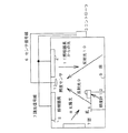
図1は、照明装置を示した図である。図1の照明装置は、照明に使用される電力を節約する目的で設置されるものであり、照度センサ1、照明器具2、コントローラ3から構成される。
【0003】
次に、照明装置の動作について説明する。一般的に、照明器具2は室内を明るくするためのものであり、明るさを変化させる機能つまり、調光機能を持っている。また、この照度センサ1は、照明器具2の光や太陽光8によって変化する室内の照度を検出するものであり、天井に設置される。なお、一般的な室内の照度は、床や机上面に設置された照度計12によって測定されるが、この天井に設置された照度センサ1が検出する照度とは、照明器具からの光11や太陽光8が、机4や床5で反射された反射光9、10の照度であり、この反射光9、10の照度結果からコントローラ3が机上面照度を算出する。なお、照度センサ1は検出した照度を直流電圧に変換し、その直流電圧を照度センサ信号としてセンサ信号線6を介してコントローラ3に送る。
【0004】
次に、コントローラ3は、照度センサ1からセンサ信号線6を介して送られてきた照度センサ信号をもとに目標照度に必要電力の演算を行い、その演算結果に応じて照明器具2の電力(照明出力)を制御する。
【0005】
また、図7は従来のコントローラと照度センサの接続関係を示した図である。この図に示されるように、コントローラ3と照度センサ1間は、センサ電源線20、センサ信号線6、GND線21の3線で接続されている。なお、センサ電源線20は照度センサ1を動作させるのに必要な電圧(DC8または12V)をコントローラ3から照度センサ1に対して送電するための線である。また、センサ信号線6は、照度センサ1が検出した照度を電圧信号(DC0〜5V)として照度センサ1からコントローラ3に伝送するための線である。また、GND線21は、照度センサ電源の電圧(DC8または12V)と照度センサ信号(DC0〜5V)の基準となる0V基準を定める線である。
【0006】
なお、この図7に示されるように、コントローラ3には照度設定ボリューム27が存在し、この照度設定ボリューム27は、図1に示された照明装置において、その部屋の使用者が必要とする室内の照度を設定する目的で設けられている。
【0007】
また、図8は図7のコントローラの運転機能部をブロック図化したものである。なお、この図の照度設定ボリューム27を回すと、室内の照度を変化させることができる。これは、以下に示す動作による。まず、照度設定ボリューム27を回すと、コントローラ内部の運転機能部75のA/D変換器33に供給される直流電圧が変化する。次に、(DC0〜5V)A/D変換器33では照度設定ボリューム27が設定した直流電圧(DC0〜5V)を256段階のデジタル値に変換し、この変換したデジタル値を演算部34に送る。
【0008】
一方、照度センサ1からは、照度センサ信号31(DC0〜5V)が運転機能部75のA/D変換器32に入力されるので、この入力された照度センサ信号(DC0〜5V)をA/D変換器32が256段階のデジタル値に変換し、この変換したデジタル値を演算部34に送る。
【0009】
次に、演算部34は、A/D変換器32によってデジタル値に変換された照度センサ信号と、A/D変換器33によってデジタル値に変換された照度設定ボリューム27の電圧値とを比較し、その比較結果を調光信号出力部36に送る。次に、その比較結果に応じた調光信号(PWM信号等)により、調光信号出力部36が照明器具2の電力を制御する。
【0010】
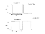
なお、このPWM信号は図11に示されるように、一定の周期(1ms等)を保ちながらそのパルス幅を変化させる信号であり、照明器具2の調光をするためのものである。即ち、この図のパルス波形111のように、パルス幅を狭くすると、照明器具2の消費電力が大きくなり、明るく点灯し、反対にパルス波形112のように、パルス幅を広くすると、照明器具2の消費電力が小さくなり、暗く点灯する。このようなPWM信号を用いて照明器具の消費電力を制御することをPWM制御という。
【0011】
なお、図5は、前述した照明装置の通常制御動作(反射面の反射率を調整した後の動作)を具体的に示したフローチャートであり、この図を用いて詳細に説明する。まず、照度センサ1がコントローラ3に対して室内の照度に応じた照度センサ信号Mを出力する。(ステップT1,T2)
次に、コントローラ3が照度センサ1から送られてきた照度センサ信号Mを読み込む。(ステップT3)
また、コントローラ3は、照度設定ボリューム27が設定した電圧値Vを読み込む。(ステップT4)
【0012】
次に、コントローラ内の演算部34が、ステップT3,T4で読み込んだ照度センサ信号電圧値Mと照度設定ボリューム電圧値Vを比較し、この比較結果を調光信号出力部に送る。次に、調光信号出力部は、この比較結果に基づいて、照度センサ信号Mと照度設定ボリューム電圧値Vが等しければ、照明器具2に対して、現在の電力、点灯率(照明器具2の最大出力点灯電力を100としたときにいくつになるかの割合を示す値)を継続するように、調光信号を出力し、照明器具2の電力を制御する。(ステップT5,T6)
【0013】
なお、等しくない場合で、照度センサ信号が大きければ、(つまり、現在の室内照度が照度設定ボリュームで設定した目標照度より明るければ)コントローラ3の調光信号出力部36は、点灯率を所定値だけ下げるように照明器具2に対して調光信号を送り、照明器具2の電力を制御する。(ステップT7、T8)
また、反対に照度センサ信号が小さければ(つまり、現在の室内照度が照度設定ボリューム27で設定した目標の照度より暗ければ)調光信号出力部36は、点灯率を所定値だけ上げるように照明器具2に対して調光信号を送り、照明器具2の電力を制御する。(ステップT7、T9)
【0014】
なお、この時、太陽光8が室内に入っても、この入った明るさに相当する出力電圧を加味して照度センサ1が現状の室内照度を出力し、この出力結果に基づいて調光信号出力部36が照明器具2の電力を制御するため、太陽光8の入室有無に関係なく常に設定値になることは言うまでもない。
【0015】
以上説明したように、ステップT3からステップT9までの動作を繰り返すことにより、照度設定ボリューム27で設定された電圧値に、照度センサ1からの出力電圧が近づくように、照明器具2の出力電力が制御されるので、室内の明るさは照度設定値の明るさに維持される。また、照明器具2の照明出力は100%点灯ではなく、コントローラ3から調光信号線7を介して照明器具2に送られてくる調光信号に応じた点灯率(5〜100%点灯)に制御するため、消費電力が節約できる。
【0016】
しかしながら、このような従来の照明装置では、後述するように、照度センサからコントローラの演算部に出力される照度センサの信号出力電圧が、部屋の環境(室内の間取りや、室内の色や、材質等による反射率の相違)により変化しても、その変化反射率に対応した電圧を出力するため、即ち、室内照度が同じ照度でないにも関わらず、反射率の変化により、同じ照度であると判断して照明器の電力を制御すると言う問題があった。これは、図1で説明したように照度センサが照度として実際に検出しているものが、照明器具の光11や太陽光8が机4や床5で反射した反射光9、10をも含めて検出しているからである。つまり照明器具からの光11や太陽光8が一定であっても、机4や床5の色、材質の変化によって机4や床5の反射率(机上面、床面で観測される光の何%が反射するかを示す値)が変化すると、その変化に対応して反射光9、10の強度が変化し、その変化の影響を受けて、照度センサ1からコントローラ3に送られる照度センサの出力信号電圧が変化するからである。
【0017】
なお、このような反射現象が実際の照明装置に与える影響としては、2つ考えられる。その1つめの影響としては、反射率が高すぎる場合である。一般的に、照度センサの出力電圧と照度制御範囲との関係を設計する場合には、照度センサが使用される室内環境を予想し、ある決められた照度制御範囲内(例えば2000lx以下)で、かつ反射率以下(例えば反射率40%以下)であれば、照度センサからコントローラに出力される照度信号電圧値が0〜5Vの範囲内になるように設定される。しかし、実際の使用環境の反射率が想定した反射率範囲を超えて高くなった場合(例えば反射率50%の場合)には、図9に示すように、実際の室内照度が最大制御照度値(2000lx)以下の1800lxであっても、照度センサ1が検出して出力する信号の電圧値が反射光の影響によって最大電圧5Vを出力してしまい、1800lx以上の照度制御ができないと言う問題である。
【0018】
次に、このような問題が発生する原因について図9を用いて詳細に説明する。なお、この図9は反射率が高すぎる場合の制御照度と照度センサ電圧の関係を示した図で、この図において、縦軸は照度センサ信号電圧、横軸は照度である。また、この図に示すように、設計反射率の上限を40%とした場合は、グラフ線92に示すように、照度2000lxで、照度センサからは、丁度5Vの信号電圧が出力される。しかし、前述したように、反射率が50%になると、グラフ線93のようになり、2000lxに達する前に、照度センサ1の出力信号電圧が5Vになってしまい、この5Vの電圧を出力する。即ち、室内照度が1800〜2000lxの間では、照度センサ1は出力電圧信号として5Vを出力し続けるため、実際の室内照度が1800lxにも関わらず、コントローラ3が2000lxであると判断して、照明器2の電力を制御する。
【0019】
このように、反射率40%の場合には、照度設定ボリューム27の設定電圧を4.75Vにすれば、図9のグラフ線92からもわかるように、室内照度を1900lxにできる。しかし、反射率50%の場合には、照度設定ボリューム27の設定電圧をどのように設定しても、室内照度は1900lxにならない。これは照度設定電圧をどのように設定しても、室内照度が1800lx以上では、前述したように、照度センサ1の出力信号電圧が常に5Vを出力するため、室内照度は1800lx止まりとなる。つまりコントローラ3は室内照度を0〜1800lxの範囲内で制御するためである。
【0020】
次に、2つ目の問題点としては、逆に反射率が低すぎる場合である。前述したように、照度センサ信号の出力電圧は、0〜5Vで、その電圧を図8のA/D変換器32が256段階(0〜256)のデジタル値に変換し、この変換結果をコントローラ3の演算部34へ送信するので、コントローラ3の演算部34は、照度センサ信号を5/256V単位で設定電圧と比較して照明器の制御電力を演算する。
【0021】
なお、この反射率が低い場合の照度センサの信号電圧と室内照度の関係を図10に示す。この図に示されるように、反射率が40%の場合は、グラフ101で、2000lxで5Vの出力電圧が照度センサ信号としてコントローラのA/D変換器33に出力される。この出力された照度センサ信号電圧5VをA/D変換器33が256段階に変換するため、5/256Vとなる。一方、この256段階の電圧に対応して、照度も2000/256lx=7.8lxとなる。従って、7.8lx単位で室内照度を制御することになる。また、反射率10%の場合は、グラフ102に示すように、照度センサから出力される信号電圧が5Vとなるのは、室内照度が8000lxの時であるから、5/256Vに対応した照度は、8000/256lx=31lxとなる。従って、室内照度を31lx単位で制御することになる。
【0022】
以上説明したように、従来の照明装置では、反射率の変化により、室内照度を7.8lx単位、または31lxの単位で制御するようになる。なお、31lx照度単位で照明器の電力を制御すると、急に暗くなったり、明るくなったりする。
【0023】
従って、このような現象を避けるために、従来の照明装置には、図7に示すように、増幅率切換スイッチ73が設けられており、この増幅率切換スイッチ73を使用者が反射率の変化に応じて操作し、照度センサの増幅器71の増幅率を変えて、その反射率(この例では40%)に対応した照度センサの出力信号電圧と照度値との関係を再設定し直して、最適な照度単位で制御することになる。
【0024】
以下に、再設定以降の動作について説明する。まず、増幅率切換スイッチ73を操作し、照度センサ1を駆動する電圧を出力する電源切換部74から、例えば8Vまたは12Vのいずれかが出力され、センサ電源線20を介して増幅率切換部72に送られる。なお、この時、増幅率切換部72に、例えば8Vが送られた時は、反射率40%において1000lxで5Vを出力する基準とした増幅率(割合)で電力を制御し、また、12Vが送られた時は、反射率40%において、3000lxで5Vを出力する基準とした増幅率で制御するようにしておくと。これらの基準値を基にして各反射率に応じて照明器の電力を制御するようになるため、例えば、8Vにセットした時は、反射率が10〜30%の範囲で変化しても、最適な照度単位で制御するようになる。また、12Vにセットした時は、反射率が30〜50%の範囲で変化しても、最適な照度単位で制御するようになる。このように増幅率を切り換えて、従来の照明装置は、反射率10〜50%の範囲を最適な照度単位で制御できるようにしている。
【0025】
【発明が解決しようとする課題】
以上のようにな従来の照明装置では、室内の各壁面や調度品の各反射率に応じて照度センサの増幅率を使用者が切り換えなければ、10lx以下の最適な照度単位で制御できないと言う問題点があった。また、部屋の中が白色系なら設定A(8V)、濃色系なら設定B(12V)と取り扱い説明書に記載したり、切換部に表示したりしなければならないと言う問題点があった。
【0026】
この発明は、以上のような問題点を解決するためになされたもので、人手を介することなく、簡単に最適な照度単位で制御する信頼性が高く、使い勝手の良い照明装置を得ることを目的とする。
【0027】
【課題を解決するための手段】
この発明に関わる照明装置においては、室内に設けられた照明器と、室内の明るさを検出する照度センサと、この照度センサの出力電圧が予め設定された基準出力電圧に近づくように、前記照度センサの出力電圧の増幅率を調整する増幅器制御部と、前記増幅率の調整時に所定の電力で前記照明器を点灯するとともに、調整後の照度センサの出力電圧に基づき前記照明器の電力を制御する調光信号出力部とを備えたものである。
【0028】
また、室内に設けられた照明器と、室内の明るさを検出する照度センサと、この照度センサの検出結果を増幅する増幅器と、この増幅器から出力される出力信号に基づいて照明器の電力を制御する調光信号出力部と、前記増幅器の増幅率を調整する増幅器制御部と、調整モード信号を出力する動作モード制御部とを具備し、前記動作モード制御部から出力される調整モード信号に応じて、前記調光信号出力部は前記照明器の電力が所定の電力となるように制御し、前記増幅器制御部は前記増幅器の出力が予め設定された基準出力電圧に近づくように増幅率を調整するものである。
【0029】
また、前記照度センサを複数備え、前記動作モード制御部から出力される調整モード信号に応じて前記複数の照度センサのそれぞれに対応する増幅器の増幅率を調整するものである。
【0030】
また、前記増幅器制御部が、前記照度センサに設けられたものである。
【0031】
また、前記増幅器の出力と予め設定された基準値とを前記動作モード制御部で比較し、異なるときには調整モード信号を前記増幅器制御部へ出力し、前記増幅器制御部は前記増幅器の出力が予め設定された基準値に近づくように前記増幅器の増幅率を調整するものである。
【0032】
また、前記調整モード信号が、照度センサの駆動電圧であるものである。
【0033】
また、電源投入したときに、前記照度センサの出力電圧の増幅率を調整するものである。
【0034】
また、前記調整モード信号に基づいて調整表示をする表示部を具備したものである。
【0035】
また、照明器により室内を所定の明るさにするステップと、照度センサが前記所定の明るさに応じた電圧信号を出力するステップと、増幅器制御部が前記所定の明るさに応じた前記照度センサの出力電圧と基準出力電圧との比較結果に基づき前記照度センサの出力電圧の増幅率を調整するステップと、調光信号出力部が前記増幅器制御部による調整後の照度センサの出力電圧に基づき前記照明器の電力を制御するステップとを有する照明装置の制御方法に関するものである。
【0036】
【発明の実施の形態】
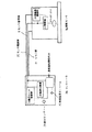
実施の形態1.図2は本発明の照明装置の実施の形態1におけるコントローラと照度センサの接続関係を示した図であり、この図に示されるように、照度センサ1bは、22は室内の明るさ(照明器の照度)を電圧信号に変換して出力するフォトダイオード22と、このフォトダイオード22の出力電圧を増幅する増幅器23と、この増幅器23の増幅率を変える増幅器制御部とで構成されている。また、コントローラ3bは、運転又は調整のいずれかの信号を後述する通常運転機能部28の調光信号選択部35及び電源切換部26を介してセンサの増幅器制御部24へ送信する動作モード制御部25と、この動作モード制御部25からの動作モード信号である運転・調整モード信号に基づいて、調整信号が出力されている時は調整信号であり、センサ駆動電圧となる例えば8Vを、また、運転信号が出力されている時は運転信号であり、センサ駆動電圧となる例えば12Vを、センサ電源線20を介して照度センサ1bの増幅器制御部24へ送信する電源切換部と、照度センサ1bからの出力信号電圧と照度設定ボリューム27の設定電圧とを比較して照明器2の電力を制御する通常運転機能部28と、で構成されている。
【0037】
また、この通常運転機能部28は、図3の通常運転機能部のブロック図に示すように、照度センサ1bからの電圧信号31を256段階のデジタル値に変換するA/D変換器32と、照度設定ボリューム27の設定電圧を256段階のデジタル値に変換するA/D変換器33と、これらのA/D変換器32、33が変換した結果を比較演算する演算部34と、前述の動作モード制御部25からの送信信号に基づいて、調整信号が送信された時は、所定の電力(例えば80%の電力)を出力するように、運転信号が送信された時は、演算部34の演算結果を出力するように指示する調光信号選択部35と、この調光信号選択部35の指示結果に基づいて照明器2の電力を制御する調光信号出力部36と、を具備している。
【0038】
なお、コントローラ、照度センサ、及び照明器具の各接続配線は従来の技術で説明した通りであり、説明を割愛する。
【0039】
次に、このように構成された本発明の実施の形態1の動作について、図4を用いて説明する。なお、この図4は本発明の実施の形態1における照度制御装置のフローチャート図である。
【0040】
まず、太陽光が入らない状態で、電源が投入されると、コントローラの動作モード制御部25は調整信号である8Vを、通常運転機能部28内の調光信号選択部35へ送信する。この送信信号に基づいて調光信号選択部35は、定格電力の80%で照明器2を点灯させる調整信号を調光信号出力部36へ送信する。これにより、調光信号出力部36は照明器2の電力を制御するので、室内は80%相当の明るさになる。(ステップS1、S2)
【0041】
次に、照度センサ1bは、この明るさに相当する照度センサ信号Mである照度信号電圧をセンサ信号線6を介してコントローラの動作モード制御部25に出力する。(ステップS3)
【0042】
次に、動作モード制御部25は、照度センサ1bからの照度センサ信号Mを読み込み。(ステップS4)
この読み込んだ照度センサ信号Mと予め設定された基準出力電圧信号(3V)とを比較し、この比較結果で、照度センサ信号Mと設定基準電圧信号(3V)との差が無ければ、即ち、同じであれば、センサの増幅器制御部24及び調光信号選択部35へ調整完了信号(通常運転信号)である12Vを送信するステップ11に移る。しかし、この比較結果で、照度センサ信号Mと設定基準電圧信号(3V)とに差が有れば、センサの増幅器制御部24及び調光信号選択部35へ調整信号である8Vを送信するステップ6に移る。(ステップS5)
【0043】
次に、ステップ6に移って上記内容が処理されると、次のステップS7では、この送信された調整信号である8Vに基づいて、コントローラが照明器の定格電力80%の明るさを維持しながら、一方、センサの増幅器制御部24は照度センサ信号Mと設定基準電圧信号(3V)との差、又は大小を比較する。この比較結果で、照度センサ信号Mが設定基準電圧信号(3V)より大きい時には、ステップS9に移り、小さい時にはステップS8に移る。
【0044】
次に、ステップS8に移ると、増幅器制御部24が照度センサ出力信号の増幅率を所定値だけ上げて、その後ステップS3に戻る。また、ステップS9に移ると、照度センサ出力信号の増幅率を所定値だけ下げて、その後ステップS3に戻る。このようなステップS3からS9までの繰り返しにより、照度センサ1の出力信号を徐々に3Vに近づけていき、ステップS5からステップS11(調整完了後の動作)に移るようにする。
【0045】
なお、前述のステップS5からステップS11に移ると、センサの増幅器制御部24及び調光信号選択部35へ調整完了信号(通常運転信号)である12Vが送信されるので、調光信号選択部35は調光信号出力部36に80%電力の出力解除命令を送ると共に、調光信号選択部35は演算部34の演算結果に応じた調光信号を調光信号出力部36に出力するようになる。即ち、図5のフローチャートに示した通常運転制御を開始する。(ステップS12,S13)
【0046】
なお、この説明では、センサ信号線6等にのったノイズの増幅を避けて調整の信頼性を向上させるため、増幅器制御部24を照度センサに設けたが、ノイズ対策をすれば、コントローラ内に設けても良いことは言うまでもない。
【0047】
また、設定基準出力電圧(3V)にある幅を持たせ、設定基準出力電圧範囲(例えば2.9〜3.1V)として判断するようにすれば、調整時間が短くなり、スピーディに調整できるようなることは、自明である。
【0048】
また、照度センサ信号Mと設定基準電圧信号(3V)との差に応じて、増幅率を変えるようにすると、調整時間が短くなり、スピーディに調整できるようなることは、自明である。
【0049】
また、調整モード信号が、照度センサの駆動電圧であるので、調整モード信号を送信する専用配線が不要となる。
【0050】
また、調整運転から通常運転に入ったら、調整運転から通常運転になったことを示す表示ランプ(図2中の29)を点灯するようにすると、運転状態がすぐに分かる使い勝手の良い照明装置が得られる。
【0051】
以上説明したように、この発明では、コントローラの動作モード制御部が電源投入により調整モード信号を運転機能部へ送信し、この送信結果に基づいて運転機能部が照明器の電力を所定値に制御し、この制御結果における照度センサからの出力電圧と予め設定された基準出力電圧範囲とを増幅器制御部が比較して照度センサの出力電圧を調整してから、コントローラが照度センサの出力電圧に基づいて照明器の電力を制御するので、室内の床や壁等の反射面の反射率が色、材質等により変化しても、この変化した反射率に対応して室内の照度を精度良く制御する信頼性が高く、使い勝手の良い照明装置が得られる。
【0052】
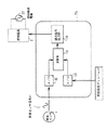
実施の形態2.図6は、この発明の実施の形態2における概略構成図であり、この図に示したように、この実施の形態2においては、1台のコントローラ3bで、各部屋に設けられた各照度センサ1b,1cからの信号に基づいて各部屋の照明器2の電力を制御し、各部屋の明るさを制御するものである。
【0053】
次に、この制御動作について説明する。まず、コントローラ3bは各照度センサ1b、1cからセンサ信号線6、66を介して送られてくる照度センサ信号を所定時間毎(例えば、3秒間隔毎)にそれぞれ交互に読みとる。
【0054】
次に、この交互読みとりのタイミングをずらした間に、コントローラ3bはそれぞれの照度センサ1b、1cの出力信号電圧を調整する。即ち、実施の形態1で説明したと同じ一連の調整動作をする。その後、その調整後のセンサ出力電圧と設定ボリューム値に基づいて各部屋内の照明器2、62の電力をそれぞれ制御し、各部屋の明るさを制御する。
【0055】
なお、このように交互に読みとって各部屋の明るさを制御する時は、各部屋の明るさは次の照度センサの出力電圧を読みとるまで、前の明るさを維持する手段を有しているのは言うまでもない。
【0056】
即ち、コントローラ3bは第1の部屋の照度センサ1bからの照度センサ信号に応じたPWM信号を調光信号線7を介して照明器具2に出力して照明器具2の電力を制御し、また同様に、第2の部屋の照度センサ1cからの照度センサ信号に応じたPWM信号を調光信号線66を介して照明器具62に出力して照明器具62の電力を制御する。
【0057】
なお、この実施の形態2では、部屋の数を2つで説明したが、2つ以上の部屋でも制御できることは言うまでもない。
【0058】
また、このようにすると、1台のコントローラで複数の部屋の明るさを制御できるようになるので、少ない構成部品で最適な室内照度を維持する経済的で、信頼性の高い照明装置が得られる。
【0059】
【発明の効果】
この発明は、以上説明したように構成されているので、以下に示すような効果を奏する。
【0060】
室内に設けられた照明器と、室内の明るさを検出する照度センサと、この照度センサの出力電圧が予め設定された基準出力電圧に近づくように、前記照度センサの出力電圧の増幅率を調整する増幅器制御部と、前記増幅率の調整時に所定の電力で前記照明器を点灯するとともに、調整後の照度センサの出力電圧に基づき前記照明器の電力を制御する調光信号出力部とを備えたので、室内の床や壁等の反射面の反射率が色、材質等により変化しても、この変化した反射面に対応して室内の照度を精度良く制御する信頼性が高く、使い勝手の良い照明装置が得られる。
【0061】
また、室内に設けられた照明器と、室内の明るさを検出する照度センサと、この照度センサの検出結果を増幅する増幅器と、この増幅器から出力される出力信号に基づいて照明器の電力を制御する調光信号出力部と、前記増幅器の増幅率を調整する増幅器制御部と、調整モード信号を出力する動作モード制御部とを具備し、前記動作モード制御部から出力される調整モード信号に応じて、前記調光信号出力部は前記照明器の電力が所定の電力となるように制御し、前記増幅器制御部は前記増幅器の出力が予め設定された基準出力電圧に近づくように増幅率を調整するので、室内の床や壁等の反射面の反射率が色、材質等により変化しても、この変化した反射面に対応して室内の照度を精度良く制御する信頼性が高く、使い勝手の良い照明装置が得られる。
【0062】
また、照度センサを複数備え、動作モード制御部から出力される調整モード信号に応じて複数の照度センサのそれぞれに対応する増幅器の増幅率を調整するので、少ない構成部品で最適な室内照度を維持する経済的で、信頼性の高い照明装置が得られる。
【0063】
また、増幅器制御部が、照度センサに設けられたので、センサ信号線等に重畳したノイズが増幅されて出力されないため、更に精度良く最適な室内照度を維持する信頼性の高い照明装置が得られる。
【0064】
また、増幅器の出力と予め設定された基準値とを動作モード制御部で比較し、異なるときには調整モード信号を前記増幅器制御部へ出力し、増幅器制御部は増幅器の出力が予め設定された基準値に近づくように前記増幅器の増幅率を調整するので、室内の床や壁等の反射面の反射率が色、材質等により変化しても、この変化した反射面に対応して室内の照度を精度良く制御する信頼性が高く、使い勝手の良い照明装置が得られる。
【0065】
また、調整モード信号が、照度センサの駆動電圧であるので、調整モード信号を送信する専用配線を不要とした経済的な照明装置が得られる。
【0066】
また、電源投入したときに前記照度センサの出力電圧の増幅率を調整するので、室内の床や壁等の反射面の反射率が色、材質等により変化しても、この変化した反射率に対応して室内の照度を精度良く制御する信頼性が高く、使い勝手の良い照明装置が得られる。
【0067】
また、調光モード信号に基づいて調整運転表示をする表示部を具備したので、運転状態がすぐに分かる使い勝手のよい照明装置が得られる。
【0068】
また、照明器により室内を所定の明るさにするステップと、照度センサが前記所定の明るさに応じた電圧信号を出力するステップと、増幅器制御部が前記所定の明るさに応じた前記照度センサの出力電圧と基準出力電圧との比較結果に基づき前記照度センサの出力電圧の増幅率を調整するステップと、調光信号出力部が前記増幅器制御部による調整後の照度センサの出力電圧に基づき前記照明器の電力を制御するステップとを有するので、室内の床や壁等の反射面の反射率が色、材質等により変化しても、この変化した反射率に対応 して室内の照度を精度良く制御する信頼性が高く、使い勝手の良い照明装置が得られる。
【図面の簡単な説明】
【図1】 照明装置を示す図である。
【図2】 本発明のコントローラと照度センサを示したものである。
【図3】 本発明のコントローラにおける通常運転機能部のブロック図である。
【図4】 本発明の照度センサ増幅率の調整動作を示すフローチャートである
【図5】 本発明及び従来の照明装置の制御動作を示すフローチャートである。
【図6】 本発明の実施の形態2における照明装置を2部屋に適用した場合の概略構成図である。
【図7】 従来の照明装置における照度センサとコントローラとの関係を示した図である。
【図8】 従来の照明装置における通常運転機能部のブロック図である。
【図9】 反射率が高すぎる場合の照度と照度センサ信号との関係を示したグラフである。
【図10】 反射率が低すぎる場合の照度と照度センサ信号との関係を示したグラフである。
【図11】 PWM信号の波形図である。
【符号の説明】
1:照度センサ 1a:照度センサ(従来例)
1b:照度センサ(発明例) 2:照明器具
3:コントローラ 3a:コントローラ(従来例)
3b:コントローラ(発明例) 4:机
5:床 6:センサ信号線
7:窓 8:太陽光
9:反射光 10:反射光
11:照明器具からの光 12:照度計
20:センサ電源線 21:GND線
22:フォトダイオード 23:増幅器
24:増幅器制御部 25:動作モード制御部
26:電源切換部 27:照度設定ボリューム
28:通常運転機能部 29:表示ランプ
31:照度センサ信号 32:A/D変換器
33:A/D変換器 34:演算部
35:調光信号選択部 36:調光信号出力部
37:照明器具電源 61:照度センサ
62:照明器具 63:机
64:床 65:センサ信号線
66:調光信号線 71:増幅器
72:増幅率切換部 73:増幅率切換スイッチ
74:電源切換部 75:通常運転機能部
91:目標照度 92:反射率40%のグラフ
93:反射率50%のグラフ 101:反射率40%のグラフ
102:反射率10%のグラフ 103:反射率20%のグラフ
111:パルス波形 112:パルス波形[0001]
BACKGROUND OF THE INVENTION
This invention controls the brightness of the room according to the reflectance of the indoor surface.-The present invention relates to a lighting device.
[0002]
[Prior art]
FIG. 1 is a diagram illustrating a lighting device. The lighting device of FIG. 1 is installed for the purpose of saving power used for lighting, and includes an illuminance sensor 1, a
[0003]
Next, the operation of the lighting device will be described. In general, the
[0004]
Next, the controller 3 calculates the required power for the target illuminance based on the illuminance sensor signal sent from the illuminance sensor 1 via the sensor signal line 6, and the power of the
[0005]
FIG. 7 is a diagram showing a connection relationship between a conventional controller and an illuminance sensor. As shown in this figure, the controller 3 and the illuminance sensor 1 are connected by three lines of a sensor power line 20, a sensor signal line 6, and a GND line 21. The sensor power supply line 20 is a line for transmitting a voltage (
[0006]
As shown in FIG. 7, the controller 3 has an illuminance setting volume 27. The illuminance setting volume 27 is a room required by the user of the room in the lighting device shown in FIG. It is provided for the purpose of setting the illuminance.
[0007]
FIG. 8 shows the control of FIG.-The driving function partblockIt is a diagram. Note that the illuminance in the room can be changed by turning the illuminance setting volume 27 in this figure. This is due to the following operations. First, when the illuminance setting volume 27 is turned, the DC voltage supplied to the A /
[0008]
On the other hand, since the illuminance sensor signal 31 (DC 0 to 5 V) is input from the illuminance sensor 1 to the A /
[0009]
Next, the calculation unit 34A / DAn illuminance sensor signal converted into a digital value by the
[0010]
As shown in FIG. 11, the PWM signal is a signal for changing the pulse width while maintaining a constant period (1 ms or the like), and is for dimming the
[0011]
FIG. 5 is a flowchart specifically showing the normal control operation (operation after adjusting the reflectance of the reflecting surface) of the above-described lighting device, and will be described in detail with reference to this drawing. First, the illuminance sensor 1 outputs an illuminance sensor signal M corresponding to the illuminance in the room to the controller 3. (Steps T1, T2)
Next, the controller 3 reads the illuminance sensor signal M sent from the illuminance sensor 1. (Step T3)
Further, the controller 3 reads the voltage value V set by the illuminance setting volume 27. (Step T4)
[0012]
Next, the
[0013]
If the illuminance sensor signal is large in a case where they are not equal (that is, if the current room illuminance is brighter than the target illuminance set by the illuminance setting volume), the dimming
Conversely, if the illuminance sensor signal is small (that is, if the current room illuminance is darker than the target illuminance set by the illuminance setting volume 27), the dimming
[0014]
At this time, even if sunlight 8 enters the room, the illuminance sensor 1 outputs the current room illuminance in consideration of the output voltage corresponding to the entered brightness, and the dimming signal is based on the output result. Since the
[0015]
As described above, the output power of the
[0016]
However, in such a conventional lighting device, as will be described later, the signal output voltage of the illuminance sensor output from the illuminance sensor to the calculation unit of the controller is the room environment (room layout, indoor color, material, etc. In order to output a voltage corresponding to the changed reflectivity even if it changes due to the difference in reflectivity due to, etc., that is, the same illuminance due to the change in reflectivity even though the room illuminance is not the same illuminance There was a problem of judging and controlling the power of the illuminator. As shown in FIG. 1, the illuminance sensor actually detected as illuminance includes the reflected light 9 and 10 reflected from the
[0017]
There are two possible effects of such a reflection phenomenon on an actual lighting device. The first effect is when the reflectivity is too high. Generally, when designing the relationship between the output voltage of the illuminance sensor and the illuminance control range, the indoor environment in which the illuminance sensor is used is predicted, and within a predetermined illuminance control range (for example, 2000 lx or less), And if it is below reflectance (for example, reflectance 40% or less), it sets so that the illumination signal voltage value output to a controller from an illumination sensor may be in the range of 0-5V. However, when the reflectance in the actual usage environment is higher than the assumed reflectance range (for example, when the reflectance is 50%), the actual room illuminance is the maximum control illuminance value as shown in FIG. Even if it is 1800 lx of (2000 lx) or less, the voltage value of the signal detected and output by the illuminance sensor 1 outputs a maximum voltage of 5 V due to the influence of reflected light, so that the illuminance control of 1800 lx or more cannot be performed. is there.
[0018]
Next, the cause of such a problem will be described in detail with reference to FIG. FIG. 9 is a diagram showing the relationship between the control illuminance and the illuminance sensor voltage when the reflectance is too high. In this figure, the vertical axis represents the illuminance sensor signal voltage and the horizontal axis represents the illuminance. As shown in this figure, when the upper limit of the design reflectivity is 40%, a signal voltage of exactly 5 V is output from the illuminance sensor at an illuminance of 2000 lx as shown by the graph line 92. However, as described above, when the reflectance reaches 50%, the graph line 93 appears, and before reaching 2000 lx, the output signal voltage of the illuminance sensor 1 becomes 5 V, and this 5 V voltage is output. . That is, when the room illuminance is between 1800 and 2000 lx, the illuminance sensor 1 continues to output 5 V as the output voltage signal.-It is determined that La 3 is 2000 lx, and the power of the
[0019]
Thus, in the case of a reflectance of 40%, if the set voltage of the illuminance setting volume 27 is set to 4.75 V, the room illuminance can be set to 1900 lx as can be seen from the graph line 92 in FIG. However, when the reflectance is 50%, the room illuminance does not become 1900 lx no matter how the setting voltage of the illuminance setting volume 27 is set. This means that no matter how the illuminance setting voltage is set, if the room illuminance is 1800 lx or more, the output signal voltage of the illuminance sensor 1 always outputs 5 V as described above, and therefore the room illuminance stops at 1800 lx. In other words, control-This is because LA 3 controls the room illuminance within the range of 0 to 1800 lx.
[0020]
The second problem is when the reflectance is too low. As described above, the output voltage of the illuminance sensor signal is 0 to 5 V, and the A /
[0021]
FIG. 10 shows the relationship between the signal voltage of the illuminance sensor and the room illuminance when the reflectance is low. As shown in this figure, when the reflectance is 40%, an output voltage of 5 V at 2000 lx is output to the A /
[0022]
As described above, in the conventional lighting device, the room illuminance is controlled in units of 7.8 lx or 31 lx by changing the reflectance. Note that when the power of the illuminator is controlled in units of 31 lx illuminance, it suddenly becomes dark or bright.
[0023]
Therefore, in order to avoid such a phenomenon, the conventional illumination apparatus is provided with an amplification factor changeover switch 73 as shown in FIG. And changing the amplification factor of the illuminance sensor amplifier 71 to reset the relationship between the output signal voltage of the illuminance sensor corresponding to the reflectance (40% in this example) and the illuminance value, It will be controlled in the optimal illuminance unit.
[0024]
The operation after resetting will be described below. First, either 8 V or 12 V, for example, is output from the power supply switching unit 74 that operates the amplification factor switching switch 73 and outputs a voltage for driving the illuminance sensor 1, and the amplification factor switching unit 72 via the sensor power supply line 20. Sent to. At this time, for example, when 8V is sent to the amplification factor switching unit 72, the power is controlled by the amplification factor (ratio) based on the output of 5V at 1000 lx at a reflectance of 40%, and 12V is When sent, 3000 at a reflectance of 40%lIt is assumed that control is performed with an amplification factor based on which 5V is output at x. Since the power of the illuminator is controlled according to each reflectance based on these reference values, for example, when set to 8 V, even if the reflectance changes in the range of 10 to 30%, It will be controlled in the optimal illuminance unit. Moreover, when set to 12V, even if the reflectance changes within a range of 30 to 50%, the control is performed in an optimum illuminance unit. By switching the amplification factor in this way, the conventional illumination device can control the range of the reflectance of 10 to 50% in an optimum illuminance unit.
[0025]
[Problems to be solved by the invention]
In the conventional lighting apparatus as described above, it cannot be controlled in an optimum illuminance unit of 10 lx or less unless the user switches the amplification factor of the illuminance sensor according to the reflectance of each wall surface or furniture in the room. There was a problem. In addition, if the room is white, setting A (8V), if it is dark, setting B (12V) must be described in the instruction manual or displayed on the switching section. .
[0026]
The present invention has been made to solve the above-described problems, and an object of the present invention is to obtain a lighting device that is highly reliable and easy to use and can be easily controlled in an optimal illuminance unit without human intervention. And
[0027]
[Means for Solving the Problems]
In the lighting device according to the present invention, the illuminator provided in the room, the illuminance sensor for detecting the brightness of the room, and the illuminance so that the output voltage of the illuminance sensor approaches a preset reference output voltage. An amplifier controller that adjusts the amplification factor of the output voltage of the sensor, and lights the illuminator with a predetermined power when the amplification factor is adjusted, and controls the power of the illuminator based on the adjusted output voltage of the illuminance sensor And a dimming signal output unit.
[0028]
In addition, an illuminator provided in the room, an illuminance sensor that detects the brightness of the room, an amplifier that amplifies the detection result of the illuminance sensor, and the power of the illuminator based on an output signal output from the amplifier A dimming signal output unit for controlling, an amplifier control unit for adjusting the amplification factor of the amplifier, and an operation mode control unit for outputting an adjustment mode signal, and the adjustment mode signal output from the operation mode control unit Accordingly, the dimming signal output unit controls the power of the illuminator to be a predetermined power, and the amplifier control unit adjusts the amplification factor so that the output of the amplifier approaches a preset reference output voltage. To be adjusted.
[0029]
A plurality of the illuminance sensors are provided, and an amplification factor of an amplifier corresponding to each of the plurality of illuminance sensors is adjusted according to an adjustment mode signal output from the operation mode control unit.
[0030]
The amplifier controller is provided in the illuminance sensor.
[0031]
Further, the output of the amplifier and a preset reference value are compared by the operation mode control unit, and when they are different, an adjustment mode signal is output to the amplifier control unit, and the amplifier control unit sets the output of the amplifier in advance. The amplification factor of the amplifier is adjusted so as to approach the set reference value.
[0032]
The adjustment mode signal is a driving voltage of the illuminance sensor.
[0033]
Further, when the power is turned on, the amplification factor of the output voltage of the illuminance sensor is adjusted.
[0034]
Also, an adjustment display is made based on the adjustment mode signal.Has a displayIt is a thing.
[0035]
A step of lighting the room with a predetermined brightness by an illuminator; a step of outputting a voltage signal according to the predetermined brightness of the illuminance sensor; and an illuminance sensor according to which the amplifier control unit corresponds to the predetermined brightness. Adjusting the amplification factor of the output voltage of the illuminance sensor based on the comparison result between the output voltage of the illuminance sensor and the reference output voltage, and the dimming signal output unit based on the output voltage of the illuminance sensor adjusted by the amplifier control unit The control method of the illuminating device which has the step which controls the electric power of an illuminator.
[0036]
DETAILED DESCRIPTION OF THE INVENTION
Embodiment 1 FIG. FIG. 2 is a diagram showing a connection relationship between the controller and the illuminance sensor in the first embodiment of the illumination device of the present invention. As shown in this figure, the
[0037]
Also thisNormalThe driving function unit 28 converts the voltage signal 31 from the
[0038]
In addition, each connection wiring of a controller, an illumination intensity sensor, and a lighting fixture is as having demonstrated with the prior art, and omits description.
[0039]
Next, the operation of the first embodiment of the present invention configured as described above will be described with reference to FIG. FIG. 4 is a flowchart of the illuminance control apparatus according to Embodiment 1 of the present invention.
[0040]
First, if the power is turned on without sunlight, the control-The operation mode control unit 25 of LA transmits 8V as an adjustment signal to the dimming
[0041]
Next, the
[0042]
Next, the operation mode control unit 25 reads the illuminance sensor signal M from the
The read illuminance sensor signal M is compared with a preset reference output voltage signal (3V), and if the comparison result shows that there is no difference between the illuminance sensor signal M and the set reference voltage signal (3V), that is, If they are the same, the process proceeds to step 11 in which 12V that is an adjustment completion signal (normal operation signal) is transmitted to the amplifier control unit 24 and the dimming
[0043]
Next, when the above contents are processed in step 6, in the next step S7, the control is performed based on the transmitted adjustment signal 8V.-On the other hand, the amplifier control unit 24 of the sensor compares the difference or magnitude between the illuminance sensor signal M and the set reference voltage signal (3V) while maintaining the brightness of the rated power of 80% of the illuminator. As a result of the comparison, when the illuminance sensor signal M is larger than the set reference voltage signal (3V), the process proceeds to step S9, and when smaller, the process proceeds to step S8.
[0044]
Next, in step S8, the amplifier control unit 24 increases the amplification factor of the illuminance sensor output signal by a predetermined value, and then returns to step S3. In step S9, the gain of the illuminance sensor output signal is decreased by a predetermined value, and then the process returns to step S3. By repeating such steps S3 to S9, the output signal of the illuminance sensor 1 is gradually brought close to 3V, and the process proceeds from step S5 to step S11 (operation after completion of adjustment).
[0045]
When the process proceeds from step S5 to step S11, 12V, which is an adjustment completion signal (normal operation signal), is transmitted to the amplifier control unit 24 and the dimming
[0046]
In this description, the amplifier control unit 24 is provided in the illuminance sensor in order to improve the reliability of the adjustment by avoiding the amplification of noise on the sensor signal line 6 and the like.-Needless to say, it may be provided in the rack.
[0047]
In addition, if the setting reference output voltage (3V) has a certain width and is determined as the setting reference output voltage range (for example, 2.9 to 3.1V), the adjustment time is shortened and the speed is reduced.-It is self-evident that you can make adjustments.
[0048]
Further, if the amplification factor is changed according to the difference between the illuminance sensor signal M and the set reference voltage signal (3V), the adjustment time is shortened and the speed is increased.-It is self-evident that you can make adjustments.
[0049]
Further, since the adjustment mode signal is a driving voltage for the illuminance sensor, a dedicated wiring for transmitting the adjustment mode signal is not necessary.
[0050]
In addition, when the normal operation is started from the adjustment operation, if a display lamp (29 in FIG. 2) indicating that the adjustment operation is changed to the normal operation is turned on, an easy-to-use lighting device that can immediately know the operation state is provided. can get.
[0051]
As described above, in the present invention, the control-The operation mode control unit of the controller transmits an adjustment mode signal to the operation function unit when the power is turned on, and the operation function unit controls the power of the illuminator to a predetermined value based on the transmission result. The amplifier controller compares the output voltage with a preset reference output voltage range and adjusts the output voltage of the illuminance sensor.-Since LA controls the power of the illuminator based on the output voltage of the illuminance sensor, even if the reflectivity of the reflective surface such as the floor or wall in the room changes depending on the color, material, etc., it corresponds to this changed reflectivity. A highly reliable and easy-to-use lighting device that accurately controls indoor illuminance can be obtained.
[0052]
Embodiment 2.FIG. 6 is a schematic configuration diagram according to the second embodiment of the present invention. As shown in FIG. 6, in this second embodiment, each illuminance sensor provided in each room by one controller 3b. Based on the signals from 1b and 1c, the power of the
[0053]
Next, this control operation will be described. First, the controller 3b alternately reads illuminance sensor signals sent from the
[0054]
Next, this alternate reading timeminGThe controller 3b adjusts the output signal voltage of each of the
[0055]
When controlling the brightness of each room by alternately reading in this way, the brightness of each room has means for maintaining the previous brightness until the output voltage of the next illuminance sensor is read. Needless to say.
[0056]
That is, the controller 3b outputs a PWM signal corresponding to the illuminance sensor signal from the
[0057]
In the second embodiment, the number of rooms has been described as two, but it goes without saying that it is possible to control two or more rooms.
[0058]
In addition, since the brightness of a plurality of rooms can be controlled by a single controller in this way, an economical and highly reliable lighting device can be obtained that maintains optimum room illuminance with a small number of components. .
[0059]
【The invention's effect】
Since the present invention is configured as described above, the following effects can be obtained.
[0060]
Adjust the amplification factor of the output voltage of the illuminance sensor so that the illuminator provided in the room, the illuminance sensor that detects the brightness of the room, and the output voltage of the illuminance sensor approach the preset reference output voltage And a dimming signal output unit that controls the power of the illuminator on the basis of the output voltage of the illuminance sensor after adjustment. Therefore, even if the reflectance of the reflective surface such as the floor or wall in the room changes depending on the color, material, etc., it is highly reliable and convenient to control the illuminance in the room with accuracy corresponding to the changed reflective surface. A lighting device is obtained.
[0061]
In addition, an illuminator provided in the room, an illuminance sensor that detects the brightness of the room, an amplifier that amplifies the detection result of the illuminance sensor, and the power of the illuminator based on an output signal output from the amplifier A dimming signal output unit for controlling, an amplifier control unit for adjusting the amplification factor of the amplifier, and an operation mode control unit for outputting an adjustment mode signal, and the adjustment mode signal output from the operation mode control unit Accordingly, the dimming signal output unit controls the power of the illuminator to be a predetermined power, and the amplifier control unit adjusts the amplification factor so that the output of the amplifier approaches a preset reference output voltage. Therefore, even if the reflectance of the reflective surface such as the floor or wall in the room changes depending on the color, material, etc., it is highly reliable to control the illuminance in the room with accuracy corresponding to the changed reflective surface, and is easy to use. Fine lighting equipment Obtained.
[0062]
In addition, multiple illuminance sensors are provided, and the amplification factor of the amplifier corresponding to each of the multiple illuminance sensors is adjusted according to the adjustment mode signal output from the operation mode control unit, so that the optimum indoor illuminance can be maintained with a small number of components. An economical and reliable lighting device can be obtained.
[0063]
In addition, since the amplifier control unit is provided in the illuminance sensor, the sensor signal line, etc.Superimposed onSince the noise is not amplified and output, a highly reliable lighting device that maintains the optimum indoor illuminance with higher accuracy can be obtained.
[0064]
Further, the output of the amplifier is compared with a preset reference value by the operation mode control unit, and when they are different, the adjustment mode signal is output to the amplifier control unit, and the amplifier control unit outputs the reference value of the amplifier set in advance. Since the amplification factor of the amplifier is adjusted so as to be closer to, even if the reflectance of the reflective surface such as the floor or wall in the room changes depending on the color, material, etc., the illuminance in the room can be accurately adjusted according to the changed reflective surface. A highly reliable lighting device with high control reliability and high usability can be obtained.
[0065]
Further, since the adjustment mode signal is the driving voltage of the illuminance sensor, an economical illumination device that does not require a dedicated wiring for transmitting the adjustment mode signal can be obtained.
[0066]
In addition, since the amplification factor of the output voltage of the illuminance sensor is adjusted when the power is turned on, even if the reflectance of the reflective surface such as the floor or wall in the room changes depending on the color, material, etc., this changed reflectance is supported. Thus, a highly reliable and easy-to-use lighting device that accurately controls the illuminance in the room can be obtained.
[0067]
Moreover, since the display part which performs adjustment driving | operation display based on the light control mode signal was comprised, the illuminating device with the ease of use which can understand a driving | running state immediately is obtained.
[0068]
A step of lighting the room with a predetermined brightness by an illuminator; a step of outputting a voltage signal according to the predetermined brightness of the illuminance sensor; and an illuminance sensor according to which the amplifier control unit corresponds to the predetermined brightness. Adjusting the amplification factor of the output voltage of the illuminance sensor based on the comparison result between the output voltage of the illuminance sensor and the reference output voltage, and the dimming signal output unit based on the output voltage of the illuminance sensor adjusted by the amplifier control unit To control the power of the illuminator, even if the reflectance of the reflective surface such as the floor or wall in the room changes depending on the color, material, etc. Thus, a highly reliable and easy-to-use lighting device that accurately controls the illuminance in the room can be obtained.
[Brief description of the drawings]
FIG. 1 is a diagram showing a lighting device.
FIG. 2 shows a controller and an illuminance sensor according to the present invention.
FIG. 3 is a block diagram of a normal operation function unit in the controller of the present invention.
FIG. 4 is a flowchart showing an adjustment operation of the illuminance sensor gain of the present invention.
FIG. 5 is a flowchart showing a control operation of the present invention and a conventional lighting device.
FIG. 6 is a schematic configuration diagram in the case where the lighting apparatus according to
FIG. 7 is a diagram showing a relationship between an illuminance sensor and a controller in a conventional lighting device.
FIG. 8 is a block diagram of a normal operation function unit in a conventional lighting device.
FIG. 9 is a graph showing the relationship between the illuminance and the illuminance sensor signal when the reflectance is too high.
FIG. 10 is a graph showing the relationship between the illuminance and the illuminance sensor signal when the reflectance is too low.
FIG. 11 is a waveform diagram of a PWM signal.
[Explanation of symbols]
1: Illuminance sensor 1a: Illuminance sensor (conventional example)
1b: Illuminance sensor (invention example) 2: Lighting equipment
3: Controller 3a: Controller (conventional example)
3b: Controller (invention example) 4: Desk
5: Floor 6: Sensor signal line
7: Window 8: Sunlight
9: Reflected light 10: Reflected light
11: Light from lighting equipment 12: Illuminance meter
20: Sensor power line 21: GND line
22: Photodiode 23: Amplifier
24: Amplifier control unit 25: Operation mode control unit
26: Power supply switching unit 27: Illuminance setting volume
28: Normal operation function section 29: Indicator lamp
31: Illuminance sensor signal 32: A / D converter
33: A / D converter 34: Calculation unit
35: Dimming signal selection unit 36: Dimming signal output unit
37: Lighting fixture power supply 61: Illuminance sensor
62: Lighting equipment 63: Desk
64: Floor 65: Sensor signal line
66: Dimming signal line 71: Amplifier
72: Amplification rate switching unit 73: Amplification rate switching switch
74: Power supply switching unit 75: Normal operation function unit
91: Graph of target illuminance 92: Reflectance 40%
93: Graph with 50% reflectivity 101: Graph with 40% reflectivity
102: Graph with 10% reflectivity 103: Graph with 20% reflectivity
111: Pulse waveform 112: Pulse waveform
Claims (9)
Priority Applications (1)
| Application Number | Priority Date | Filing Date | Title |
|---|---|---|---|
| JP25648896A JP3774952B2 (en) | 1996-09-27 | 1996-09-27 | Lighting device and control method thereof |
Applications Claiming Priority (1)
| Application Number | Priority Date | Filing Date | Title |
|---|---|---|---|
| JP25648896A JP3774952B2 (en) | 1996-09-27 | 1996-09-27 | Lighting device and control method thereof |
Publications (2)
| Publication Number | Publication Date |
|---|---|
| JPH10106757A JPH10106757A (en) | 1998-04-24 |
| JP3774952B2 true JP3774952B2 (en) | 2006-05-17 |
Family
ID=17293343
Family Applications (1)
| Application Number | Title | Priority Date | Filing Date |
|---|---|---|---|
| JP25648896A Expired - Lifetime JP3774952B2 (en) | 1996-09-27 | 1996-09-27 | Lighting device and control method thereof |
Country Status (1)
| Country | Link |
|---|---|
| JP (1) | JP3774952B2 (en) |
Families Citing this family (7)
| Publication number | Priority date | Publication date | Assignee | Title |
|---|---|---|---|---|
| JP4734745B2 (en) * | 2001-03-30 | 2011-07-27 | 学校法人東海大学 | Lighting system |
| JP4590327B2 (en) * | 2005-08-29 | 2010-12-01 | 京都電機器株式会社 | Discharge lamp lighting device |
| JP5180926B2 (en) * | 2009-07-27 | 2013-04-10 | パナソニック株式会社 | Lighting control system |
| JP5592637B2 (en) * | 2009-11-25 | 2014-09-17 | パナソニック株式会社 | Lighting control device, lighting control system, and lighting control device |
| JP2011204643A (en) * | 2010-03-26 | 2011-10-13 | Panasonic Electric Works Co Ltd | Lighting system |
| JP5624366B2 (en) * | 2010-05-26 | 2014-11-12 | パナソニック株式会社 | Lighting system |
| KR102589610B1 (en) * | 2014-11-25 | 2023-10-13 | 오르보테크 엘티디. | Illumination intensity control for inspection system |
-
1996
- 1996-09-27 JP JP25648896A patent/JP3774952B2/en not_active Expired - Lifetime
Also Published As
| Publication number | Publication date |
|---|---|
| JPH10106757A (en) | 1998-04-24 |
Similar Documents
| Publication | Publication Date | Title |
|---|---|---|
| US5406173A (en) | Apparatus and method for adjusting lights according to the level of ambient light | |
| JP3774952B2 (en) | Lighting device and control method thereof | |
| JP3954183B2 (en) | Automatic illumination control device | |
| JP2745379B2 (en) | Fluorescent lighting dimming system | |
| JPH0896968A (en) | Lighting system | |
| JP2003347068A (en) | Lighting control device | |
| JPH11238579A (en) | Lighting system | |
| JP3867449B2 (en) | Lighting device | |
| EP2278419A1 (en) | Motion detector and load control unit | |
| JPH11251073A (en) | Light modulating device | |
| JPH10270178A (en) | Illuminating device | |
| JPH0969391A (en) | Illumination lighting device | |
| JP3788099B2 (en) | Lighting system | |
| JPH1140374A (en) | Lighting control device | |
| JPH11144882A (en) | Automatic luminance setting method in illumination control system | |
| JP2002299076A (en) | Lighting system | |
| JP2567540Y2 (en) | Lighting equipment | |
| JPH05152077A (en) | Automatic dimming system | |
| JPH07147192A (en) | Lighting control device | |
| JP2008010202A (en) | Lighting control device | |
| JPH10125476A (en) | Illumination controller | |
| JPH0696866A (en) | Illumination control system | |
| JPH0714679A (en) | Automatic lighting/extinguishing controller for illuminating lamp | |
| JPH09250800A (en) | Controlling device of air conditioner | |
| JPH09306675A (en) | Lighting system |
Legal Events
| Date | Code | Title | Description |
|---|---|---|---|
| A521 | Written amendment |
Free format text: JAPANESE INTERMEDIATE CODE: A523 Effective date: 20040130 |
|
| RD01 | Notification of change of attorney |
Free format text: JAPANESE INTERMEDIATE CODE: A7421 Effective date: 20040715 |
|
| A977 | Report on retrieval |
Free format text: JAPANESE INTERMEDIATE CODE: A971007 Effective date: 20060124 |
|
| TRDD | Decision of grant or rejection written | ||
| A01 | Written decision to grant a patent or to grant a registration (utility model) |
Free format text: JAPANESE INTERMEDIATE CODE: A01 Effective date: 20060131 |
|
| A61 | First payment of annual fees (during grant procedure) |
Free format text: JAPANESE INTERMEDIATE CODE: A61 Effective date: 20060213 |
|
| FPAY | Renewal fee payment (event date is renewal date of database) |
Free format text: PAYMENT UNTIL: 20100303 Year of fee payment: 4 |
|
| FPAY | Renewal fee payment (event date is renewal date of database) |
Free format text: PAYMENT UNTIL: 20100303 Year of fee payment: 4 |
|
| FPAY | Renewal fee payment (event date is renewal date of database) |
Free format text: PAYMENT UNTIL: 20110303 Year of fee payment: 5 |
|
| FPAY | Renewal fee payment (event date is renewal date of database) |
Free format text: PAYMENT UNTIL: 20110303 Year of fee payment: 5 |
|
| FPAY | Renewal fee payment (event date is renewal date of database) |
Free format text: PAYMENT UNTIL: 20120303 Year of fee payment: 6 |
|
| FPAY | Renewal fee payment (event date is renewal date of database) |
Free format text: PAYMENT UNTIL: 20130303 Year of fee payment: 7 |