JP3774635B2 - Electrical connector with cover case - Google Patents
Electrical connector with cover case Download PDFInfo
- Publication number
- JP3774635B2 JP3774635B2 JP2001063356A JP2001063356A JP3774635B2 JP 3774635 B2 JP3774635 B2 JP 3774635B2 JP 2001063356 A JP2001063356 A JP 2001063356A JP 2001063356 A JP2001063356 A JP 2001063356A JP 3774635 B2 JP3774635 B2 JP 3774635B2
- Authority
- JP
- Japan
- Prior art keywords
- locking
- cover case
- arm
- metal body
- electrical connector
- Prior art date
- Legal status (The legal status is an assumption and is not a legal conclusion. Google has not performed a legal analysis and makes no representation as to the accuracy of the status listed.)
- Expired - Fee Related
Links
Images


Landscapes
- Details Of Connecting Devices For Male And Female Coupling (AREA)
- Manufacturing Of Electrical Connectors (AREA)
- Connector Housings Or Holding Contact Members (AREA)
Description
【0001】
【発明の属する技術分野】
本発明はカバーケースを有する電気コネクタに関する。
【0002】
【従来の技術】
この種の電気コネクタとしては、特開平11−149957に開示されているものが知られている。
【0003】
この公知のコネクタは、添付図面の図5に見られるような、絶縁材をモールド成形して作られた円筒のカバーケース50を有している。この例では、端子を保持せるハウジングの周面に金属板を屈曲して作られたシールドケースが組立てられ、その組立体(図示せず)が上記カバーケース50の開口部51を経て矢印Aの方向から挿入組立される。上記カバーケース50には、ケースの肉厚方向に貫通せる係止孔52が複数位置に形成されており、これに対応した位置でシールドケースを切り起して形成された係止爪が上記係止孔52と係止して、組立体の抜け防止がなされる。又、上記カバーケース50には、相手コネクタとの係合ロック用にシールドケースが有するロック腕を押圧してロック解除するロック腕54が上記カバーケース50の側部に設けられている。
【0004】
【発明が解決しようとする課題】
しかしながら、上述した公知のコネクタにあっては、カバーケースに貫通した係止孔を形成するために不具合をもたらす。
【0005】
先ず、外観上、係止孔が露呈していて見栄えが良くない。
【0006】
次に、係止孔を形成することによる強度低下を防止するために、カバーケースを少なくとも局部的に肉厚なものにせねばならない。しかし、これにも限界がある。
【0007】
さらには、係止孔に汚れ物質が溜まりやすい。
【0008】
本発明は、かかる不具合を解消し、係止孔の無いカバーケースをもつ電気コネクタを提供することを目的とする。
【0009】
【課題を解決するための手段】
本発明に係る電気コネクタは、端子を保持する絶縁ハウジングに金属体を取りつけられて形成する半組立体が、筒状の一体成形カバーケースへ開口から挿入組立されて成り、上記半組立体とカバーケースが互いに抜け防止を図る係止手段を備えている。
【0010】
かかる電気コネクタにおいて、本発明では、金属体は金属板を打抜きそして屈曲加工することにより一部材として作られていて反挿入方向に延びる係止腕を有し、該係止腕は側方への可撓性を有すると共に該係止腕の延出方向先端部に係止部を備え、カバーケースは内面に上記係止部が係止するための係止突出部が設けられ、上記係止部と係止突出部は、互いの当接時に上記係止腕が係止部にて弾性撓み変形して係止位置へもたらされた後に弾性変形が解除されて原形に回復することにより、金属体とカバーケースが互いに係止し合って抜け防止され、上記金属体が相手コネクタとのロックをなす弾性撓み可能なロック腕を有し、カバーケースが該ロック腕を押圧してロック解除を行う解除腕を有し、カバーケースは該解除腕に可撓性を付与するためスリットが解除腕を境界付けるように形成されており、該解除腕を介してロック腕を押圧して該ロック腕に撓み変形を与えることにより相手コネクタとのロック解除が可能となっていることを特徴としている。
【0011】
このような本発明によると、ハウジングに金属体が取りつけられて形成する半組立体がカバーケースへ挿入組立てされると、上記半組立体の金属体に設けられた係止部がカバーケース内面の係止突出部と係止し合い、抜けが防止される。カバーケースの係止突出部は内面に形成されているので、外面には孔や突部等がなく平坦であり、カバーケースの外観は損なわれることなく、又、孔がないので強度低下や汚れ物質の進入ということもない。金属体は係止部が係止孔であっても、材質が金属なので、強度低下は殆んどない。又、加工も容易になされる。
【0012】
本発明において、上記金属体はハウジングの周囲の少なくとも一部に組立てられているようにすることができる。
【0014】
係止突出部は、複数位置に設けられる場合、これらがカバーケースの内面のうちの一つの平面上に位置していることが、カバーケースの製造上好ましい。
【0015】
上記のコネクタは、金属体が相手コネクタとのロックをなす弾性撓み可能なロック腕を有し、カバーケースが該ロック腕を押圧してロック解除を行う解除腕を有し、カバーケースは該解除腕に可撓性を付与するためスリットが解除腕を境界付けるように形成されており、該解除腕を介してロック腕を押圧して該ロック腕に撓み変形を与えることによりロック解除が可能となっている電気コネクタに適用可能である。
【0017】
【発明の実施の形態】
以下、添付図面の図1ないし図4にもとづき、本発明の実施の形態を説明する。
【0018】
<第一実施形態>
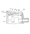
図1において、電気コネクタは、端子(図示せず)を保持せるハウジング1、これに取付けられる金属体10そして電気絶縁材から成るカバーケース20を有している。
【0019】
ハウジング1は、前部(図にて左部)に相手コネクタとの嵌合のための嵌合凹部2,3が形成されており、この中に端子が配設されている。該ハウジング1の中間部には、該ハウジング1がカバーケース20内に挿入されるとき、その挿入方向位置を定めるためのフランジ部4を有し、カバーケース20の前端面と当接するようになっており、又、後部には後方に延出する板状の腕部5が設けられ、カバーケース20への挿入に際して案内されるようになっている。該腕部5の側面には、係止突起6が設けられている。この係止突起6は、ハウジング1が金属体へ上方から組込まれる際のロックを行うもので、上端面が段状の係止面6A、そして下部が相手方係止孔に入り込むための斜面状の導入面6Bが形成されている。
【0020】
金属体10は、金属板を打ち抜きそして屈曲成形加工して作られており、底板部11と側板部12とを有して略U字状をなしている。底板部11の前部には切り起しにより形成された二つの起立部13が対向して設けられていて、この起立部13に窓状の係止孔13Aが形成されている。この起立部13は上記ハウジング1の腕部5の外側面に接する位置にあり、係止孔13Aはこの腕部5に設けられた既述の係止突起6が嵌まり込み係止する形状そして寸法となっている。又、底板部11の両側の中間側部には係止腕14が設けられている。該係止腕14は前方に向け延びていて側方に可撓性を有している。この係止腕14には、前方に向け外側へ拡がる斜面14Aと該斜面14Aの前端部位置に段状の係止部14Bとが形成されている。上記斜面14Aは、この金属体10がカバーケース20内へ挿入されたときに係止腕14を内方へ撓ませる力をカバーケースから受け、又、係止部14Bはこの撓みが解除されたときカバーケースの対応係止部と係止する機能をそれぞれ有する。
【0021】
さらに、上記底板部11には、後部に窓状の係止孔15が形成されている。この係止孔15も、金属体10がカバーケース20内に挿入されたとき、カバーケース20の対応係止突出部と係止する機能を有する。
【0022】
又、上記底板部11は、側板部12との連絡部16がL字状に屈曲され上方にもち上がるように成形されている。これは、金属体10がカバーケース20内へ挿入される際に、この連絡部16の下方に、対応部位(後述の下案内部26)との干渉を回避する空間を形成するためのものである。
【0023】
上記金属体10の側板部12の前部には、前方に延出するロック腕17が設けられている。該ロック腕17は、相手コネクタ(図示せず)との接続の際に、内方に撓んで相手コネクタの相当部位に係止する翼状の係止爪17Aが側方に突出して設けられている。
【0024】
カバーケース20は、絶縁材からモールド成形により横長な角筒状に作られている。該カバーケース20の上下面は平坦で孔などは形成されていない。該カバーケース20の前部は角筒状の開口部21を形成し、後部には、ケーブルを通すスリーブ部22が設けられている。又、両側の側部には内方に向け可撓性を有する解除腕23が設けられている。該解除腕23は、該解除腕の後部における根元部を除いて周囲にスリット24を形成することにより弾性撓みが可能となっている。側方に若干膨出して、該解除腕23を内方へ押す押圧部23Aが形成されている。この解除腕23は、押圧部23Aでの押圧力を受けて内方へ撓み、これによって上記金属体10のロック腕17を同方向へ押すことにより撓みを生じせしめ、ロックを解除するものである。二つの解除腕23の内面間距離は、上記金属体10の二つの側板部12の外面間距離と略等しくなっている。
【0025】
上記解除腕23の内面上部とカバーケース20の内底面には、前後に延びるレール状の上案内部25と下案内部26とがそれぞれ設けられている。この上案内部25と下案内部26とは、両者の間で、上記金属体10の側板部12の上縁と下縁とを案内する役を担っている。そして上記下案内部26には、前後方向中間部に溝部26Aが形成され、又、該溝部26Aの前端近傍に、丸味を帯びた段部26Bが形成されている。この段部26Bと上記溝部26Aの前端面が係止突出部を形成する。
【0026】
さらに、上記カバーケース20の内底面の後部(奥部)には、もう一種の係止突出部27が形成されている。該係止突出部27は、既述の金属体10の係止孔15と係止するもので、前面が斜面部27A、そして後面はカバーケース内底面に直角な段状の係止面27Bを形成している。
【0027】
かかる本実施形態の電気コネクタは、次の要領で組み立てられる。
1 )先ず、端子を保持せるハウジング1へ金属体10取り付けて半組立体を形成する。ハウジング1は、図1に一点鎖線Pで示されるごとく、上方から金属体1上に配置され、ハウジング1の係止突起6が金属体10の係止孔13Aに弾性的に嵌まり込み、ここで互いが固定される。端子へのケーブルの結線は、ハウジングと金属体との組み立ての前あるいは後に行われる。
2 )次に、ケーブルをスリーブ部22内へ通し、ハウジング1と金属体10との半組立体を、図1の一点鎖線Qのごとく、カバーケース20の中へ挿入する。
3 ) 半組立体のカバーケース20への挿入は、金属体10の側板部12がカバーケース20の上案内部25と下案内部26との間で案内されながら進行し、所定位置まで行われる。その際、金属体10の係止腕14は斜面14Aにてカバーケース20の段部26Bからの押圧力を受けて内方に撓み、又、係止孔15の後縁部は係止突出部27の斜面部27Aからの力を受けて上方へ撓み、挿入の進行を可能とする。又、カバーケース20が薄くできているときには、内底面自体が撓みを生じ係止突出部27が変位し、係止孔15との係合を容易にする。
4 )挿入が所定位置まで達すると、係止腕14そして係止孔15の後縁部の撓みは解除され、係止腕14は係止部14Bが溝26Aの前端面と、係止孔15は前縁部が係止面27Bとそれぞれ係止して、金属体10はカバーケース20からの抜けが防止される。
【0028】
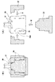
<第二実施形態>
図2に示す第二実施形態は、図1の第一実施形態における金属体10の係止腕14を変形したこと、第一実施形態の係止孔15がないこと、において特徴がある。なお、図2にて図1のものと共通部位には同一符号を付しその説明を省略する。
【0029】
係止腕34は、きわめて簡単な形状をなしていて、前方に直状に延びており、肩部34Aが丸味をもっていて、該肩部34Aが図1における斜面14Aの機能を有している。
【0030】
前出の実施形態では、カバーケースとの係止は金属体との間でなされていたが、ハウジングとの間でも、重複して係止させることも可能である。
【0031】
ハウジング1は、第一実施形態の場合同様、図3に示されるように、ハウジングの係止突起6と金属体10係止孔13Aとの間の係止により、金属体10とで半組立体を形成する。このハウジング1は、腕部5の下腕部に、側方に突出し前方に延びる図1に見られる金属体10の係止腕14と同様の形状の係止腕7が設けられている。この係止腕7は、図1の係止腕14と同様、カバーケース20の溝26Aの前端面と係止する。又、ハウジング1は、後部に板状部8が延出して設けられ、ここに係止孔9が形成されている。この係止孔9は、カバーケース20の係止突出部27と係止する。したがって、図1のカバーケース20がそのまま使える。
【0032】
又、本例では、金属体10が側板部12の後部にU字状曲部18を有していて、この曲部18を介して起立部13と連通している。
【0033】
図4には、前出の実施形態におけるカバーケース20の製造方法が示されている。
【0034】
筒状のカバーケース20を樹脂によりモールド成形するには、カバーケース20の外形面を定めるための外金型(図示せず)と、図4(A)に図示の第一スライド金型31そして二つの第二スライド金型32とを用いる。
【0035】
上記第一スライド金型31はカバーケースの開口部の方向Qから外金型内へ挿入され、二つの第二スライド金型32は側方向Rから挿入される。したがって、第一スライド金型31と第二スライド金型32は、それらの挿入方向前端面が、カバーケースに設けられる下案内部26と係止突出部27を形成するように段状に形状づけられている。その際、第二スライド金型32は、カバーケースの解除腕23の上下に形成されるスリット24(図1参照)から挿入される。
【0036】
かくして、図4(B)のごとく、カバーケースをモールド成形した後、方向Q、Rと逆方向に第一スライド金型31、第二スライド金型32を抜き出し、外金型から製品としてのカバーケースを取り出す。
【0037】
【発明の効果】
以上のように、本発明は、ハウジングとシールド体としての金属体とから成る半組立体が、カバーケースの内面に設けられた係止突部と係止して抜け止めがなされるようにしたので、カバーケースには、従来のもののような係止孔は形成されず、見栄えが良く、強度低下がなく、そして汚れ物質の進入阻止を向上させることができ、コネクタとしての商品価値を高める。
【図面の簡単な説明】
【図1】本発明の第一実施形態のコネクタを示し、組立前の斜視図である。
【図2】第二実施形態の金属体及びカバーケースを示す横断面図である。
【図3】 第一実施形態の変形例としてのコネクタを示し、組立前の斜視図である。
【図4】カバーケースの成形のための金型を示し、(A)は金型の組込み前、(B)は金型の組込み後の成形時を示す。
【図5】従来のコネクタ用カバーケースを示す斜視図である。
【符号の説明】
1 ハウジング
10 金属体
14,15 係止部
15 係合孔
17 ロック腕
20 カバーケース
23 解除腕
24 スリット
26,27 係止突出部[0001]
BACKGROUND OF THE INVENTION
The present invention relates to an electrical connector having a cover case.
[0002]
[Prior art]
As this type of electrical connector, one disclosed in JP-A-11-149957 is known.
[0003]
This known connector has a
[0004]
[Problems to be solved by the invention]
However, the above-described known connector causes a problem because the locking hole penetrating the cover case is formed.
[0005]
First, in terms of appearance, the locking holes are exposed and the appearance is not good.
[0006]
Next, in order to prevent a decrease in strength due to the formation of the locking hole, the cover case must be at least locally thick. However, this also has a limit.
[0007]
Furthermore, dirt substances tend to accumulate in the locking holes.
[0008]
An object of the present invention is to provide an electrical connector having a cover case that eliminates such problems and does not have a locking hole.
[0009]
[Means for Solving the Problems]
Electrical connector according to the present invention, subassembly to form attached to the metal body in an insulating housing that holds the terminal is comprised are inserted assembled from the opening to the cylindrical molded cover case, the subassemblies and the cover The case is provided with locking means for preventing the cases from coming off from each other.
[0010]
In such an electrical connector, in the present invention, the metal body is formed as one member by punching and bending a metal plate, and has a locking arm extending in the anti-insertion direction. The cover case is provided with a locking portion at the distal end in the extending direction of the locking arm, and the cover case is provided with a locking projection for locking the locking portion on the inner surface. a locking protrusion, by restoring the is released elastic deformation original shape after being brought to the locking position the locking arm when contacting each other is elastically flexural deformation at the engaging portion, the metal The body and the cover case engage with each other to prevent the metal case from being pulled out , and the metal body has an elastically bendable lock arm that locks with the mating connector, and the cover case presses the lock arm to release the lock. Has a release arm, and the cover case gives the release arm flexibility Because slits releasing arm is formed so as to bound the, and can unlock the mating connector by by pressing the lock arms through the release arm give resiliently deformed the locking arm It is characterized by that.
[0011]
According to the present invention, when the semi-assembly formed by attaching the metal body to the housing is inserted into the cover case and assembled, the locking portion provided on the metal body of the semi-assembly is formed on the inner surface of the cover case. Locking with the locking protrusions prevents slipping out. Since the locking projection of the cover case is formed on the inner surface, the outer surface is flat without holes or protrusions, etc., and the appearance of the cover case is not impaired, and there is no hole, so strength is reduced and dirt There is no entry of material. Even if the locking part is a locking hole, the metal body is made of metal, so that there is almost no decrease in strength. Processing is also easy.
[0012]
In the present invention, the metal body may be assembled to at least a part of the periphery of the housing.
[0014]
When the locking protrusions are provided at a plurality of positions, it is preferable in manufacturing the cover case that they are positioned on one plane of the inner surface of the cover case.
[0015]
The connector has an elastically bendable lock arm in which the metal body locks with the mating connector, the cover case has a release arm that releases the lock by pressing the lock arm, and the cover case is released The slit is formed so that the release arm is bounded to give flexibility to the arm, and the lock arm can be unlocked by pressing the lock arm through the release arm to give the deformation to the lock arm. Applicable to electrical connectors.
[0017]
DETAILED DESCRIPTION OF THE INVENTION
Hereinafter, embodiments of the present invention will be described with reference to FIGS. 1 to 4 of the accompanying drawings.
[0018]
<First embodiment>
In FIG. 1, the electrical connector has a
[0019]
The
[0020]
The
[0021]
Further, the
[0022]
The
[0023]
A
[0024]
The
[0025]
A rail-shaped
[0026]
Further, another type of locking
[0027]
Such an electrical connector of this embodiment is assembled in the following manner.
1) First, the mounting
2) Next, the cable passing into the
3 ) The insertion of the semi- assembly into the
4) When the insertion reaches a predetermined position, the deflection of the trailing edge of the locking
[0028]
<Second embodiment>
The second embodiment shown in FIG. 2 is characterized in that the locking
[0029]
Locking
[0030]
In the above embodiment, the cover case is locked with the metal body, but it is also possible to lock the cover case with the housing .
[0031]
As in the case of the first embodiment, as shown in FIG. 3 , the
[0032]
In this example , the
[0033]
FIG. 4 shows a method for manufacturing the
[0034]
In order to mold the
[0035]
The
[0036]
Thus, as shown in FIG. 4B, after the cover case is molded, the
[0037]
【The invention's effect】
As described above, according to the present invention, the semi- assembly composed of the housing and the metal body as the shield body is locked with the locking protrusion provided on the inner surface of the cover case so as to be prevented from coming off. since, in the cover case, the locking hole, such as a conventional one not formed, appearance is good, no strength reduction, and stain is able to improve the entrance block of material, increase the commercial value of the connector .
[Brief description of the drawings]
FIG. 1 shows a connector according to a first embodiment of the present invention and is a perspective view before assembly.
FIG. 2 is a cross-sectional view showing a metal body and a cover case of a second embodiment.
FIG. 3 shows a connector as a modification of the first embodiment, and is a perspective view before assembly.
4A and 4B show a mold for molding a cover case, where FIG. 4A shows a state before the mold is assembled, and FIG. 4B shows a molding time after the mold is assembled.
FIG. 5 is a perspective view showing a conventional connector cover case.
[Explanation of symbols]
DESCRIPTION OF
Claims (3)
Priority Applications (1)
| Application Number | Priority Date | Filing Date | Title |
|---|---|---|---|
| JP2001063356A JP3774635B2 (en) | 2001-03-07 | 2001-03-07 | Electrical connector with cover case |
Applications Claiming Priority (1)
| Application Number | Priority Date | Filing Date | Title |
|---|---|---|---|
| JP2001063356A JP3774635B2 (en) | 2001-03-07 | 2001-03-07 | Electrical connector with cover case |
Publications (2)
| Publication Number | Publication Date |
|---|---|
| JP2002270279A JP2002270279A (en) | 2002-09-20 |
| JP3774635B2 true JP3774635B2 (en) | 2006-05-17 |
Family
ID=18922365
Family Applications (1)
| Application Number | Title | Priority Date | Filing Date |
|---|---|---|---|
| JP2001063356A Expired - Fee Related JP3774635B2 (en) | 2001-03-07 | 2001-03-07 | Electrical connector with cover case |
Country Status (1)
| Country | Link |
|---|---|
| JP (1) | JP3774635B2 (en) |
Families Citing this family (4)
| Publication number | Priority date | Publication date | Assignee | Title |
|---|---|---|---|---|
| US7311526B2 (en) | 2005-09-26 | 2007-12-25 | Apple Inc. | Magnetic connector for electronic device |
| US8888500B2 (en) | 2011-06-30 | 2014-11-18 | Apple Inc. | Robust magnetic connector |
| US9065205B2 (en) | 2011-08-11 | 2015-06-23 | Apple Inc. | Connector insert having a cable crimp portion with protrusions and a receptacle having label in the front |
| US11424573B2 (en) | 2020-09-24 | 2022-08-23 | Apple Inc. | Magnetic connectors with self-centering floating contacts |
-
2001
- 2001-03-07 JP JP2001063356A patent/JP3774635B2/en not_active Expired - Fee Related
Also Published As
| Publication number | Publication date |
|---|---|
| JP2002270279A (en) | 2002-09-20 |
Similar Documents
| Publication | Publication Date | Title |
|---|---|---|
| JP2907373B2 (en) | Connector lock connection detection structure | |
| US6244880B1 (en) | Low-insertion force connector | |
| US6280262B1 (en) | Connector | |
| JP3301329B2 (en) | connector | |
| JPH04127976U (en) | connector | |
| JPH10112355A (en) | Rattling prevention structure for electrical connectors | |
| EP1091451A2 (en) | Connector | |
| JP3101203B2 (en) | Electrical connector with retainer | |
| JP3337008B2 (en) | connector | |
| JP3311228B2 (en) | Connector with terminal lock | |
| JP3774635B2 (en) | Electrical connector with cover case | |
| EP3879637B1 (en) | Connector lock structure | |
| JP3247073B2 (en) | Double locking member for connector | |
| JP3741350B2 (en) | Half-mating prevention connector | |
| KR20240076679A (en) | Connector | |
| JP5217602B2 (en) | connector | |
| JPH0945411A (en) | Connector with holder | |
| JPH10189118A (en) | Terminal fixing structure to housing | |
| JP3702748B2 (en) | connector | |
| JP5129792B2 (en) | Electrical connector assembly | |
| EP1162695A1 (en) | Connector for a flat cable | |
| JP4076691B2 (en) | Double locking connector | |
| JPH1140262A (en) | connector | |
| JP3193271B2 (en) | connector | |
| US20240235081A1 (en) | Electrical connection device |
Legal Events
| Date | Code | Title | Description |
|---|---|---|---|
| A621 | Written request for application examination |
Free format text: JAPANESE INTERMEDIATE CODE: A621 Effective date: 20030116 |
|
| A977 | Report on retrieval |
Free format text: JAPANESE INTERMEDIATE CODE: A971007 Effective date: 20050218 |
|
| A131 | Notification of reasons for refusal |
Free format text: JAPANESE INTERMEDIATE CODE: A131 Effective date: 20050616 |
|
| A521 | Written amendment |
Free format text: JAPANESE INTERMEDIATE CODE: A523 Effective date: 20050801 |
|
| A131 | Notification of reasons for refusal |
Free format text: JAPANESE INTERMEDIATE CODE: A131 Effective date: 20051026 |
|
| A521 | Written amendment |
Free format text: JAPANESE INTERMEDIATE CODE: A523 Effective date: 20051226 |
|
| TRDD | Decision of grant or rejection written | ||
| A01 | Written decision to grant a patent or to grant a registration (utility model) |
Free format text: JAPANESE INTERMEDIATE CODE: A01 Effective date: 20060127 |
|
| A61 | First payment of annual fees (during grant procedure) |
Free format text: JAPANESE INTERMEDIATE CODE: A61 Effective date: 20060220 |
|
| R150 | Certificate of patent or registration of utility model |
Free format text: JAPANESE INTERMEDIATE CODE: R150 |
|
| FPAY | Renewal fee payment (event date is renewal date of database) |
Free format text: PAYMENT UNTIL: 20090224 Year of fee payment: 3 |
|
| FPAY | Renewal fee payment (event date is renewal date of database) |
Free format text: PAYMENT UNTIL: 20120224 Year of fee payment: 6 |
|
| FPAY | Renewal fee payment (event date is renewal date of database) |
Free format text: PAYMENT UNTIL: 20120224 Year of fee payment: 6 |
|
| FPAY | Renewal fee payment (event date is renewal date of database) |
Free format text: PAYMENT UNTIL: 20120224 Year of fee payment: 6 |
|
| LAPS | Cancellation because of no payment of annual fees |