JP3774591B2 - Retry sequence learning method and magnetic disk apparatus to which the learning method is applied - Google Patents
Retry sequence learning method and magnetic disk apparatus to which the learning method is applied Download PDFInfo
- Publication number
- JP3774591B2 JP3774591B2 JP18777699A JP18777699A JP3774591B2 JP 3774591 B2 JP3774591 B2 JP 3774591B2 JP 18777699 A JP18777699 A JP 18777699A JP 18777699 A JP18777699 A JP 18777699A JP 3774591 B2 JP3774591 B2 JP 3774591B2
- Authority
- JP
- Japan
- Prior art keywords
- retry
- magnetic disk
- steps
- read
- error
- Prior art date
- Legal status (The legal status is an assumption and is not a legal conclusion. Google has not performed a legal analysis and makes no representation as to the accuracy of the status listed.)
- Expired - Fee Related
Links
Images


Landscapes
- Digital Magnetic Recording (AREA)
Description
【0001】
【発明の属する技術分野】
本発明は、リードエラーが発生した場合のリトライシーケンス学習方法及びこの学習方法を適用した磁気ディスク装置に関する。
【0002】
【従来の技術】
一般に磁気ディスク装置は、リードデータにエラーが発生した場合、このエラーを回復するためにエラー回復コードであるECCを使用したデータ訂正を行い、このECCによってもデータを訂正できなかった場合にはデータのリトライリードを行っている。
【0003】
このデータのエラーを引き起こす要因としては、ランダムなノイズによるS/N比の劣化の他に、(1)ディスク上の欠陥、(2)Thermal Asperity(熱障害;TA)、(3)オフトラックライト、(4)波形変動、(5)動作環境の変動によるリード信号波形の特性変化などが挙げられる。
【0004】
前記(1)ディスク上の欠陥は、大きさや範囲によっては欠陥部分でのデータエラーだけでなく、振幅変化による再生回路の自動振幅調整機能(AGC)や位相同期ループ(PLL)が誤動作してリード波形とデータ復号クロックにずれが生じ、バースト的なエラーを招くこともある。特に近年では高記録密度化(高BPI化)が進み、従来では問題にならなかったサイズの小さな欠陥が問題となってきている。
【0005】
前記(2)TAは、リードヘッドに磁気抵抗効果素子(MR素子)を使用している場合に見られる現象である。このMR素子は、外部磁界によって素子の持つ磁化の向きが変化すると素子の抵抗が変化する磁気抵抗効果を利用し、MR素子に一定のバイアス電流を流し、前記抵抗の変化による素子の電圧変化を出力信号として得るものであり、前記TAは、磁気ディスク上に突起などに前記MR素子が接触して摩擦により素子の温度が上昇し、金属材料であるMR素子の抵抗が変化して本来の信号成分にその熱による抵抗変化分が重畳し波形を本来あるべき形から変形させる現象である。
【0006】
前記(3)波形変動は、ライトヘッドによるライト磁界(書き込み時の磁界)がリードヘッドに影響を及ぼすことによって発生し易く、前記データ書き込み時にライト磁界がリードヘッド中の磁区構造を一時的に異なる構造へと遷移させ、出力振幅の変化や波形の上下非対称を引き起こす現象である。
【0007】
前記(4)オフトラックライトは、本来ライトされるべき位置からオフセットした位置にデータトラックが書き込まれる現象であり、オフセットしたトラックのみでなく隣接トラックにも影響を与える現象である。このトラック位置を本来の位置からオフセットして書き込んだ場合、当然正しい位置でデータを読んでも期待したリード信号波形は得られないためエラーレートの劣化を招く。このオフセットライトは、今後さらにトラック密度が増大すればますます問題となる現象である。
【0008】
(5)前記動作環境が引き起こす現象は、例えば高温や低気圧状態でヘッドの浮上量が変化し、これによりリード波形の分解能が変化することが挙げられる。現在主流となっているパーシャルレスポンスと呼ばれる信号処理方式では、分解能の変化による等化誤差はエラーレートに大きな劣化を生じる。
【0009】
この様にリードエラーにはさまざまな要因があり、エラー発生時に再読込を行うリトライリードにより、その要因を想定してさまざまなエラー回避方法が実行される。このエラー回避方法をエラー要因対応に次に説明する。
【0010】
(1)ディスク上欠陥に対するエラー回避方法:
このエラー回避方法は、欠陥が通常のデータ範囲に存在するか同期を取るためのPLO SYNC部に存在するかによって異なるが、前者の場合は再生回路のゲイン変更を行なったりデータ復号方式を切り替えたりする方法が採られ、後者の場合PLLの引き込みタイミングを変更するなどの処置が採られる。
【0011】
(2)TAに対するエラー回避方法:
このTAの影響を軽減するためのエラー回避方法は、TAの応答が信号成分の周波数に比べて遅いことを利用し、ハイパスフィルタ(HPF)のカットオフ周波数を上げることによってリード波形からTA成分を除去する方法が採られる。またAGC(自動利得制御回路)やPLL(Phase Locked Loop:データセパレータ回路)がTA波形に応答することによってエラーが後続の部分まで伝搬するのを防ぐために、AGCやPLLの動作をホールドする方法が併せて行われる。
【0012】
(3)波形変動に対するエラー回避方法:
この波形変動の回避方法は、ライトヘッドによる磁界がリードヘッドに影響を及ぼすことに起因するため、再びライトヘッドから磁界を発生させてリードヘッドを安定な磁区構造に戻す方法が採られている。
この回避方法においては、リードデータを壊さないよう一度データの書かれていないトラックにシークしてライト電流を流しヘッドの磁区構造を安定状態に戻した後、再度目標のトラックにシークし直してリードを実行する必要がある。この復旧のためのライト動作は、データをライトするためではなく単にライト磁界を発生させるためだけのライトであるためダミーライトと呼ばれる。
【0013】
(4)オフトラックライトに対するエラー回避方法:
この回避方法は、オフトラックして書き込んでしてしまったデータトラックに対して前記オフセット分だけ本来のリード位置からずらした位置での読込を行えば良く、オフセット方向やその値が分からないために、いくつかのオフセット値でリトライリードを行なうことによって行われる。
【0014】
(5)その他のエラー回避方法:
この回避方法は、特定の要因に対するエラー回復方法ではないが、R/Wチャネルによって発行される、エラーが発生したと推定される場所に関する情報を利用し、ソフトウェアでより効果的なエラー訂正を行なうイレージャ訂正などが挙げられる。
【0015】
このように従来技術による磁気ディスク装置には、エラー回復方法を含んださまざまなリトライステップがリトライシーケンスとして登録されており、リードエラーが発生した場合に実行される。このリトライステップの実行順序は、エラー要因の発生頻度やそのステップを実行するのに要する時間を考慮し、最初にオフセットリード、次にダミーライト、次にフィルタ設定の変更といったように実行の順序が装置構成時に決定されたまま固定している。
【0016】
従って従来技術による磁気ディスク装置は、エラー要因によってはエラー回復に有効なステップがリトライシーケンスの末尾の方に登録されており、無駄なリトライステップを多数実行した後でなければエラー回復をすることができず、エラーの回復までに時間を費やすと言う不具合があった。
【0017】
従来技術においては、前記不具合を解決するために、例えば特開平10−134528号公報に記載されている如く、リトライシーケンスに登録されたリトライステップを複数のステップを含むグループに分割しておき、エラー発生時にはエラーの種類を判別し、判別されたエラーの種類に応じてグループ内から特定のリトライステップを選択的に実行することにより無駄なリトライステップを避ける方法が提案されている。
【0018】
この方法を図1を参照して説明する。図1は、前記公報中に示されたエラー回復プロシージャのステップ例である。図に示すステップは、大別して、どのようなタイプのエラーにおいても実行するステップ1〜4のグループと、エラータイプにしたがって選択的に実行するために区分けされた複数のグループA以降とに分けられる。前記ステップ1〜4のグループは、前回と同条件にて再読込を行うSYNC1〜2と、トラック位置をずらして再読込を行うオフトラック1〜2のステップとから構成される。
【0019】
前記グループAは、TA用にAGCをホールドするステップ5,サーボエラー用にデータ・スレショルド調整を行うステップ6,ミスリード用にサーボ・スレショルド調整を行うステップ7とから構成され、グループBは、TA用にバタフライ・シークを行うステップ8,サーボエラー用にオフトラックシークを行うステップ9,ミスリード用にMRバイアスの変更を行うステップ10とから構成されている。
【0020】
前記各グループにはTAエラー回復用、サーボ・エラー回復用、およびその他の読み取り不良(ミス・リード)エラー回復用の3つのステップが含まれ、本例においてTAエラーが発生した場合には、ステップ1、2、3、4、5、8、11が順次実行され、サーボ・エラーの場合には、1、2、3、4、6、9、12が順次実行され、ミス・リードの場合には、1、2、3、4、7、10、13が順次実行される。
【0021】
【発明が解決しようとする課題】
前述の公報中に示された無駄なリトライステップを避ける方法は、リトライシーケンスに入る前にエラーの要因を特定する必要があるが、前述したようにエラー要因は多種存在し、TAを除いた他のエラー要因をリトライシーケンスに入る前に特定することは困難であるため、ほとんどのリードエラーはミス・リード回復用のステップをグループ順に実行することとなり、実質的に無駄なステップを避けることは困難であると言う不具合があった。
【0022】
本発明の目的は、前記従来技術による不具合を除去することであり、無駄なリトライステップの実行を防止することができるリトライシーケンス学習方法及び該学習方法を適用した磁気ディスク装置を提供することである。
【0023】
【課題を解決するための手段】
前記目的を達成するため本発明は、磁気ディスクに書き込んだデータを再生し、リードエラーが発生した際に所定のステップを含むシーケンスに従ってリトライを行う磁気ディスク装置のリトライシーケンス学習方法であって、リトライシーケンスでのステップの順序を可変とし、該ステップの実行順序を、過去に行われたリトライシーケンスにおいてデータに誤りなくリードできたステップから優先的に実行することを第1の特徴とする。
【0024】
更に本発明は、磁気ディスクに書き込んだデータを再生し、リードエラーが発生した際に所定のステップを含むシーケンスに従ってリトライを行う磁気ディスク装置において、リトライシーケンスでのステップの順序を可変とし、該ステップの実行順序を、過去に行われたリトライシーケンスにおいてデータに誤りなくリードできたステップから優先的に実行することを第2の特徴とする。
【0025】
また本発明は、データを記録する磁気ディスクと、該磁気ディスクに対しデータの記録再生を行う磁気ヘッドと、該磁気ヘッドを用いてデータの記録再生を行う記録再生回路と、複数のステップを含むリトライシーケンスを記憶する不揮発性メモリと、書き換え可能なメモリとを含み、 磁気ディスクに書き込んだデータを再生し、リードエラーが発生した際に前記リトライシーケンスに従ってリトライを行う磁気ディスク装置において、前記磁気ディスクからリードしたデータにエラーがあった場合、前記不揮発性メモリに記憶したリトライシーケンスによる所定順序の複数のステップによるリトライを実行し、該リトライにおいてデータに誤りなくリードできたステップの順序を書き換え可能なメモリに記憶し、次のリードエラーが発生した際に前記書き換え可能なメモリに記憶した順序で複数のステップを実行してリトライすることを第3の特徴とする。
【0026】
【発明の実施の形態】
以下、本発明によるリトライシーケンス学習方法及び該学習方法を適用した磁気ディスク装置を図面を参照して詳細に説明する。図2は、本発明が適用される磁気ディスク装置の機構を説明するための図である。
図2に示す磁気ディスク装置は、スピンドル21に回転自在に保持された磁気ディスク22と、該磁気ディスク22上に位置してキャリッジに保持され且つボイスコイルモータ(VCM) 23により回動される磁気ヘッド24と、該磁気ヘッド24によりデータの記録再生を行う記録再生回路の機能の一部を担うリード・ライト(R/W) IC 25と、これら回路機構を収納する筐体20とを備える。
【0027】
この磁気ディスク装置は、スピンドル21の回転により磁気ディスク22を所定回転数回転した状態で、ボイスコイルモータ23が駆動することにより磁気ヘッド25を磁気ディスク24上の任意のトラックに位置決めし、リード・ライトIC25によりデータの記録再生を行う様に構成されている。
【0028】
前記磁気ヘッド24でリードしたアナログ信号は、リード・ライトIC25を通じてR/Wチャネルに送られデジタルデータへ再生される。ライト・リードされるデータにはエラーをチェックするためのコードが付加されており、データを再生した際にそれがライトしたデータと正しいかどうか判定できる。リードしたデータに誤りがあると判定された場合、データ訂正やリトライリードが実行される。
【0029】
本実施形態では、エラーを回復するための複数のリトライシーケンス及びこの学習方法は磁気ディスク装置構成時にROMなどの不揮発性メモリ上に格納されている。
【0030】
このエラー回復を行うステップは、例えば図3に示す如く、各ステップにはretry[n](0〜n)という名前が割り当てられ、例えばretry[0]は単純な再リード,retry[1]は−1タップヘッド位置をずらしたオフセットリード,retry[2]は+1タップヘッド位置をずらしたオフセットリード,retry[3]は−2タップヘッド位置をずらしたオフセットリード,retry[4]は+2タップヘッド位置をずらしたオフセットリード,retry[5]はEQ係数を変更した再リード、retry[6]はPLLをホールドした状態の再リード,retry[7]はAGCをホールドした状態の再リード,retry[8]はMR素子用のダミーライト,retry[9]はAGCのゲインを変更した状態の再リード,retry[10]はHPFの周波数(fc)を変更した再リード,retry[11]はイレージャを訂正した再リードを行うことを表している。即ち図3は、使用される(n+1)個のステップ有るエラー回復の一例が、それぞれretry[ ]というステップ名で割り当てられていることを説明する図である。
【0031】
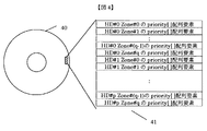
本実施形態によるエラーを回復するための複数のリトライシーケンス及びこの学習方法を次に図4を参照して説明する。図4は、本実施形態による磁気ディスク40上にリトライの優先順位を記述した配列priority[]の要素が表41のように保存されている様子を示す。
【0032】
この保存されている配列要素は、前回の磁気ディスク装置動作時の全ての条件によるリトライリードを行った結果に基づくリトライシーケンス学習結果であり、例えばヘッド番号0(HD#0)のゾーン番号0(Zone#0)の如く各磁気ヘッド及び磁気ディスク上のゾーン毎に配列要素を割り当てる。本例ではゾーン数(q+1)、ヘッド本数(p+1)としている。
【0033】
本実施形態は、磁気ディスク装置起動時には前記配列要素を磁気ディスクから読み込み、例えばRAMなどの書き換え可能なメモリ上にpriority[ ]配列の要素として記憶する。例えばあるゾーン・ヘッドに関してディスク上にpriority[ ]が「1、3、4、0、5、10、9、…」と保存されていた場合、書き換え可能なメモリには図5のようにpriority[0]=1、priority[1]=3、priority[2]=4、priority[3]=0、priority[4]=5、priority[5]=10、priority[6]=9、…と記憶する。
【0034】
図6はエラーが発生した場合のリトライ手順と、その結果を元に次回のリトライステップ順序を変更する様子を示したフローチャートである。ここではエラー回復を行うステップを表した図3を元に説明を行なうためにリトライステップ数が(n+1)個の場合として説明する。
【0035】
本処理は、まずエラーが発生しリトライシーケンスに入ると、まずk=0をセットし(ステップ60)、次いでpriority[k]すなわちpriority[0]に該当するリトライステップを実行する(ステップ61)。このリトライステップは、priority[0]が”1”であるため、まずretry[1]が実行される、即ち図2の「−1タップオフセットリード」のステップが行われる。
【0036】
次に本処理は、前記ステップ61によりリトライが成功したか否かを判定し(ステップ62)、ここでリトライリードに成功しなかった場合はステップ63にフローが進み、ここで既に決められた全ステップのリトライが実行されたかが判断される。決められた回数のリトライステップを実行してもエラーを回復できなかった場合にはステップ64に示したようにリトライ失敗となる。
【0037】
まだ決められた全ステップのリトライを実行していなかった場合(ステップ63のYes)、kの値に”1”を加算して再びステップ61に戻る。
このステップ65によりkの値がインクリメントされ、今度のステップ61ではpriority[1]に示されたステップ、ここでの例ではretry[3]が実行される、即ち図3に示した「−2タップオフセットリード」が実行される。
以降リトライリードに成功(ステップ62のYES)するか、決められた回数のリトライが実行される(ステップ63のNo)まで、同様の手順が繰り返される。
【0038】
ここでは、k=4までのリトライステップでリードに成功しなかったものとし、ステップ65までフローが進んだと仮定すると、本ステップ65でkがインクリメントされk=5となり、ステップ61へ戻り、ステップ62においてretry[priority[5]]=retry[10]すなわち「HPFのfc変更」が実行され、再リードが行われる。
【0039】
このステップでリードに成功したとするとステップ66へと進み、最初のリトライステップでリードに成功していれば、リトライステップ順序の変更は行なわれずリトライ終了(ステップ67)となるが、k=0でないため次のステップ68へと進み、次回のリトライのためにステップ順序の変更が行われる。
【0040】
このステップ順序の変更は、今回リードに成功した「HPFのfc変更」が次回のリトライ時に最初(k=0)に実行されるようにするため、図5のpriority[0]を10に変更する必要がある。これがステップ68中のpriority[0]=priority[k]である。また、このときに元のpriority[0]の情報が失われないように、一時的にtempという変数に避難させている。これがステップ68中の(temp=priority[0])である。
【0041】
以下の操作では今回の1〜k−1番目のステップが、次回の2〜k番目に実行されるようにpriority[ ]配列の内容を操作している。k+1番目以降のリトライステップ順序には変更は加えられない。
本処理は、以上の手順を全て実行するとリトライの終了となる(ステップ69)。
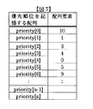
【0042】
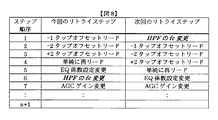
上記の操作の結果priority[]配列要素順序は、当初の図5のものから図7に示す如く変更され、次回のリトライ時にはステップの実行順序は図8に示す如く、今回のリトライが「−1タップオフセットリード」から開始していたものを次回においては「HPFのfcの変更」から開始する様に変更する。
【0043】
従って本実施形態によれば、リトライに要する時間を各ステップで同じとすると、この例の場合、次回のリトライでは成功までに要する時間を今回と比べて1/6に短縮することができる。即ち、本発明は、リトライシーケンスでのステップの順序を可変とし、その順序を、過去に行われたリトライシーケンスにおいてデータに誤りなくリードできたステップから優先的に実行する、換言すればリトライシーケンスで実行されるステップの順序を過去にどのステップが効果的に作用したかに応じて学習する機能を有することにより、無駄なリトライステップが実行されるのを避けることができる。
【0044】
次に本発明の他の実施形態であるリトライステップの回数を学習する手順について説明する。
図9は、前記図4に示したリトライステップの他の例を示し、磁気ディスク90上に各リトライステップの回数を記述した配列time[]の要素が表91のように保存されている様子を示す。
【0045】
ここに保存されている配列要素は、ゾーン数(q+1)、ヘッド本数(p+1)の例における、前回の磁気ディスク装置動作時のリトライシーケンス学習結果である。前記実施形態同様に磁気ディスク装置起動時にはこれが磁気ディスク上からリードされ、例えばRAMなどの書き換え可能なメモリ上のtime[]に例えば図10の如く記憶される。例えばあるゾーン・ヘッドに関してディスク上にtime[]が「2、1、1、3、2、1、1、…」と保存されていた場合、書き換え可能なメモリ上には図10のようにtime[0]=2、time[1]=1、time[2]=1、time[3]=3、time[4]=2、time[5]=1、time[6]=1、…と記憶される。
【0046】
図11、はエラーが発生した場合のリトライ手順と、その結果を元に次回のリトライステップ回数を変更する様子を示したフローチャートである。ここではリトライステップ数が(n+1)個の場合を仮定した。
【0047】
本処理は、エラーが発生しリトライシーケンスに入ると、まずk=0をセットし(ステップ20)、次いでretry[0],retry[1],…,retry[n]がリトライに成功するまで順番に実行される。この時それぞれのリトライステップは、それぞれ図11中の符号110部分のループに示すようにtime[0],time[1],…time[n]回ずつ繰り返し実行される。
【0048】
前記符号110部分の処理は、lにtime[0]をセットし(ステップ20)、次いで前記lが0より大きいか判定し(ステップ21)、retry[0]のステップ、ここではpriority[0]が”1”であるためretry[1](図2の「−1タップオフセットリード」)のステップを実行し(ステップ23)、リードの成功有無を判定し(ステップ24)、成功しない場合はlから1を減算(ステップ25)してから前記ステップ22に戻り、リトライに成功するまで順番に再度ステップ23によるretry[1]〜retry[n]がリトライに成功するまで順番に実行される。
【0049】
以下前述の図3と図10を例に説明すると、「単純に再リード」がtime[0]として2回、「−1タップオフセットリード」がtime[1]回として1回、「+1タップオフセットリード」がtime[2]回として1回、「−2タップオフセットリード」がtime[3]回として回、…のように実行される。
【0050】
ここで例えば「−2タップオフセットリード」でリトライに成功したとすると、図11のステップ111によりリトライステップの次回のリトライシーケンスでの回数が変更される。本例のステップ111では今回の回数+1回となる場合を示したが、ここは他の値に設定しても良い。上記の手順の結果により図10に示したリトライ回数を記憶する配列の要素を図12のように変化させる。
【0051】
これにより本実施形態は、各ステップの回数を可変とし、過去に行われたリトライシーケンスの結果に応じてその回数を学習させる、即ち過去のリトライシーケンスでエラーなくリードできたステップの回数を他のステップより多数回実行することにより、リトライの成功率を向上させることができる。
【0052】
尚、図11に示した実施形態では省略したが、ステップあたりの最大リトライ回数に上限を与え、ある特定のステップだけにより時間の消費を防止することが考えられる。この場合、リトライシーケンスが繰り返し実行され、全てのリトライの回数が上限に張り付くと、各ステップ間の回数に優劣がなくなってしまうため、この対策として、例えば全ステップのリトライ回数の合計を管理し、合計回数がある値を超え場合、リトライに成功したステップの回数を増やす時に他のステップの回数を減らす様にすることが考えられる。この場合には、リトライ回数が0になり実行されないステップができるのを避けるため、リトライ回数の下限も例えば1と決めておく必要がある。
【0053】
本発明は、前述の2つの実施形態を組み合わし、リトライステップの順序と回数を共に変更することもできる。
図13は、この前記2つの実施形態を組み合わしたリトライ手順と、リトライ結果を元にリトライステップの順序と回数を変更する手順を表すフローチャートである。
【0054】
本処理は、エラーが発生しリトライシーケンスに入ると、まずk=0をセットし(ステップ31)、次いでlにtime[priority[k]]にk=0をセットし(ステップ32)、次いで前記lが0より大きいか判定し(ステップ33)、time[priority[0]]のステップを実行する(ステップ34)。ここではpriority[0]が”1”であるためretry[1](図2の「−1タップオフセットリード」)のステップを実行し(ステップ34)、リードの成功有無を判定し(ステップ35)、成功しない場合はlから1を減算(ステップ36)してから前記ステップ33に戻り、リトライに成功するまで順番に再度ステップ24によるretry[priority[1]]〜retry[priority[n]]がリトライに成功するまで順番に実行される。
ここで前記ステップ33において前記lが0より小さいと判定され(ステップ33のNO)、kがnより小さいとき(ステップ37におけるYES)、kに1を加算してステップ32に戻って処理を続行する。
【0055】
このように本発明は、無駄なリトライステップが実行されるのを避けるために、リトライシーケンスでのステップの順序を可変とし、その順序を、過去に行われたリトライシーケンスにおいてデータに誤りなくリードできたステップから優先的に実行することにより、リトライシーケンスで実行されるステップの順序を過去にどのステップが効果的に作用したかに応じて学習することができる。
【0056】
またステップ順序だけでなく、各ステップの回数を可変とし、過去に行われたリトライシーケンスの結果に応じてその回数を学習させ、過去のリトライシーケンスでエラーなくリードできたステップの回数を他のステップより多数回実行することによりリトライの成功率を向上することができる。
【0057】
尚、本発明は次に述べる実施形態としても表すことができる。
<実施形態1> データを記録するための磁気ディスクと、該磁気ディスクに対しデータの記録・再生を行う磁気ヘッドと、該磁気ヘッドに接続されたデータの記録再生回路と、該磁気ディスクと該磁気ヘッドおよび該記録再生回路の動作を制御する制御回路と、該制御回路の動作手順を記憶する不揮発性メモリと、書き換え可能なメモリからなる磁気ディスク装置で、該磁気ディスク装置は少なくとも2本のヘッドを有するか、あるいは少なくとも2つのゾーンに分割されており、該磁気ディスクから該磁気ヘッドを用いてリードしたデータに誤りがあった場合にはリトライシーケンスが実行され、該リトライシーケンスは少なくとも2種類のリトライステップを有し、該リトライステップは前記不揮発性メモリに保持されており、該リトライシーケンスで実行されるリトライステップの順序あるいは各リトライステップの回数あるいはリトライステップの順序および回数は起動時にはあらかじめ定められており、磁気ディスク装置の起動後にリトライシーケンスで実行されるリトライステップの順序あるいは各リトライステップの回数あるいはリトライステップの順序および回数が変化可能であり、該リトライステップの順序あるいは各リトライステップの回数あるいはリトライステップの順序および回数が前記書き換え可能なメモリに記憶されていることを特徴とする磁気ディスク装置。
【0058】
<実施形態2> リトライシーケンスで実行されるリトライステップの順序が、直前までに実行されたリトライシーケンスにおいて、どのリトライステップでデータに誤りなくリードできたかに応じて変化することを特徴とする実施形態1記載の磁気ディスク装置。
<実施形態3> 直前に実行されたリトライシーケンスにおいてデータに誤りなくリードできたリトライステップが、その直後のリトライシーケンス時に最初に実行されることを特徴とする実施形態1又は2記載の磁気ディスク装置。
<実施形態4> リトライシーケンスで実行されるリトライステップの順序が、ヘッドあるいはゾーンあるいはヘッドおよびゾーン毎に変化可能であることを特徴とする実施形態1記載のの磁気ディスク装置。
<実施形態5> 磁気ディスク装置起動後に変化したリトライシーケンスで実行されるリトライステップの順序を、磁気ディスク上に保存することを特徴とする実施形態1記載の磁気ディスク装置。
<実施形態6> 磁気ディスク装置を起動後最初のリトライシーケンスでのリトライステップの実行順序は、実施形態5で磁気ディスク上に保存された順序に従うことを特徴とする実施形態1記載の磁気ディスク装置。
【0059】
<実施形態7> リトライシーケンスで実行される各リトライステップの回数が、直前までに実行されたリトライシーケンスにおいてどのリトライステップでデータに誤りなくリードできたかに応じて変化することを特徴とする実施形態1記載の磁気ディスク装置。
【0060】
<実施形態8> リトライシーケンスで実行される各リトライステップの回数が、ヘッドあるいはゾーンあるいはヘッドおよびゾーン毎に変化可能であることを特徴とする実施形態1又は2記載の磁気ディスク装置。
<実施形態9> 磁気ディスク装置起動後に変化したリトライシーケンスで実行される各リトライステップの回数を、磁気ディスク上に保存することを特徴とする実施形態1記載の磁気ディスク装置。
<実施形態10> 磁気ディスク装置を起動後最初のリトライシーケンスでの各リトライステップの回数は、実施形態9で磁気ディスク上に保存された順序に従うことを特徴とする実施形態1記載の磁気ディスク装置。
【0061】
【発明の効果】
本発明を利用すれば、エラーに対して最も有効なエラー回復ステップが優先的にかつ多数回実行されるために、リトライの成功率向上とパフォーマンスの低下を最小限に抑えることが可能となる。またゾーンおよびヘッド毎にリトライステップ実行順序および回数が独立であるため、学習したためのパフォーマンス低下を抑えることが可能である。
【0062】
さらに学習したリトライ順序および回数を保存しておくことによって、次回起動時には直後からリトライ学習効果を有効に利用できる。
【図面の簡単な説明】
【図1】従来技術による磁気ディスク装置のリトライシーケンスを説明するための図。
【図2】本発明の一実施形態による磁気ディスク装置の機構を示す図。
【図3】本発明の一実施形態による不揮発性メモリ上に格納されるエラー回復を行うステップを説明するための図。
【図4】本発実施形態によりリトライステップの実行順序を示すpriority[ ]配列が、ディスク上にゾーンおよびヘッド毎に保存されていることを説明するための図。
【図5】本発実施形態によるRAM上に記憶されているあるゾーン・ヘッドのpriority[ ]の配列要素を説明するための図。
【図6】本発実施形態によるリードエラーが発生した場合に実行されるリトライステップ手順と、そのリトライ結果を元に次回のリトライステップ実行順序を変更する手順を説明するためのフローチャート図。
【図7】本発実施形態によりリトライが実行された後に、RAM上に記憶されたpriority[ ]が変化した一動作例を説明するための図。
【図8】本発実施形態によるリトライの前後でのリトライステップ実行順序変化の一動作例を説明するための図。
【図9】本発明の他の発実施形態によるリトライステップの回数を示すtime[ ]配列が、ディスク上にゾーンおよびヘッド毎に保存されていることを説明するための図。
【図10】他の実施形態によるRAM上に記憶されているあるゾーン・ヘッドのtime[ ]の配列要素を説明するための図。
【図11】他の実施形態によるリードエラーが発生した場合に実行されるリトライステップ手順と、そのリトライ結果を元に次回のリトライステップ回数を変更する手順を説明するためのフローチャート図。
【図12】他の実施形態によるリトライが実行された後に、RAM上に記憶されたtime[ ]が変化した一動作例を説明するための図。
【図13】他の実施形態によるリードエラーが発生した場合に実行されるリトライステップ手順と、そのリトライ結果を元に次回のリトライステップの順序および回数を変更する手順を説明するためのフローチャート図。
【符号の説明】
20:磁気ディスク装置筐体、21:スピンドル、22:磁気ディスク、23:ボイスコイルモーター(VCM)、24:磁気ヘッド、25:リードライト(R/W) IC、40:磁気ディスク、41:磁気ディスク上にライトされたpriority[ ]の配列要素、90:磁気ディスク、91:磁気ディスク上にライトされたtime[ ]の配列要素。[0001]
BACKGROUND OF THE INVENTION
The present invention relates to a retry sequence learning method when a read error occurs and a magnetic disk device to which the learning method is applied.
[0002]
[Prior art]
In general, when an error occurs in read data, the magnetic disk unit performs data correction using ECC, which is an error recovery code, in order to recover this error. Retry lead is done.
[0003]
Factors that cause this data error include (1) Defect on disk, (2) Thermal Asperity (TA), (3) Off-track write, in addition to S / N ratio degradation due to random noise. (4) Waveform fluctuation, (5) Change in characteristics of read signal waveform due to fluctuation in operating environment, and the like.
[0004]
(1) Depending on the size and range, the defect on the disk is not only caused by a data error at the defective part, but also by an automatic amplitude adjustment function (AGC) or a phase locked loop (PLL) of the reproduction circuit due to an amplitude change. There may be a deviation between the waveform and the data decoding clock, resulting in bursty errors. In particular, in recent years, recording density has increased (higher BPI), and defects of small size that have not been a problem in the past have become a problem.
[0005]
(2) TA is a phenomenon seen when a magnetoresistive effect element (MR element) is used in the read head. This MR element utilizes the magnetoresistive effect that changes the resistance of the element when the magnetization direction of the element changes due to an external magnetic field, and allows a constant bias current to flow through the MR element, thereby changing the voltage of the element due to the change in resistance. The TA is obtained as an output signal. The TA is the original signal when the MR element comes into contact with a protrusion on the magnetic disk, the temperature of the element rises due to friction, and the resistance of the MR element, which is a metal material, changes. This is a phenomenon in which the resistance change due to the heat is superimposed on the component and the waveform is deformed from the original shape.
[0006]
The (3) waveform variation is likely to occur when a write magnetic field (write magnetic field) by the write head affects the read head, and the write magnetic field temporarily changes the magnetic domain structure in the read head during the data write. This is a phenomenon that causes a transition to a structure and causes a change in output amplitude and a vertical asymmetry of the waveform.
[0007]
The (4) off-track write is a phenomenon in which a data track is written at a position that is offset from the position to be originally written, and is a phenomenon that affects not only the offset track but also an adjacent track. If the track position is written with an offset from the original position, the expected read signal waveform cannot be obtained even if the data is read at the correct position, so that the error rate is deteriorated. This offset light is a phenomenon that becomes more problematic as the track density further increases in the future.
[0008]
(5) The phenomenon caused by the operating environment is, for example, that the flying height of the head changes at a high temperature or low atmospheric pressure, thereby changing the resolution of the read waveform. In a signal processing method called partial response, which is currently mainstream, an equalization error due to a change in resolution causes a large deterioration in error rate.
[0009]
As described above, there are various factors in the read error, and various error avoiding methods are executed by assuming the cause by retry reading in which rereading is performed when an error occurs. This error avoidance method will be described next in response to error factors.
[0010]
(1) Error avoidance method for defects on disk:
This error avoidance method differs depending on whether the defect exists in the normal data range or in the PLO SYNC section for synchronization, but in the former case, the gain of the reproduction circuit is changed or the data decoding method is switched. In the latter case, measures such as changing the pull-in timing of the PLL are taken.
[0011]
(2) Error avoidance method for TA:
The error avoidance method to reduce the influence of this TA uses the fact that the response of TA is slower than the frequency of the signal component. By increasing the cutoff frequency of the high pass filter (HPF), the TA component is removed from the lead waveform. The method of removing is taken. There is also a method to hold the operation of AGC and PLL in order to prevent the error from propagating to the following part by AGC (automatic gain control circuit) and PLL (Phase Locked Loop: data separator circuit) responding to the TA waveform. It is done together.
[0012]
(3) Error avoidance method for waveform fluctuation:
Since this method of avoiding the waveform fluctuation is caused by the magnetic field generated by the write head affecting the read head, a method of returning the read head to a stable magnetic domain structure by generating a magnetic field from the write head again is employed.
In this workaround, seek to the track where data has not been written once to avoid damage to the read data, flow the write current, return the magnetic domain structure of the head to a stable state, and seek again to the target track. Need to run. The write operation for recovery is called dummy write because it is a write for generating a write magnetic field, not for writing data.
[0013]
(4) Error avoidance method for off-track light:
In order to avoid this, the data track that has been written off-track may be read at a position shifted from the original read position by the offset, and the offset direction and its value are not known. This is done by performing a retry read with several offset values.
[0014]
(5) Other error avoidance methods:
This workaround is not an error recovery method for a specific factor, but uses the information about the place where the error is presumed issued by the R / W channel to perform more effective error correction in software. Examples include erasure correction.
[0015]
Thus, in the conventional magnetic disk apparatus, various retry steps including an error recovery method are registered as a retry sequence, which is executed when a read error occurs. The execution order of this retry step takes into account the frequency of error factors and the time required to execute that step, and the order of execution is first such as offset read, then dummy write, and then filter setting change. It is fixed as determined at the time of device configuration.
[0016]
Therefore, in the magnetic disk device according to the prior art, a step effective for error recovery is registered toward the end of the retry sequence depending on the error factor, and error recovery can be performed only after many unnecessary retry steps are executed. There was a problem that it was not possible to spend time to recover from the error.
[0017]
In the prior art, in order to solve the above problem, for example, as described in Japanese Patent Application Laid-Open No. 10-134528, the retry steps registered in the retry sequence are divided into groups including a plurality of steps. A method has been proposed in which the type of error is determined when an error occurs, and a specific retry step is selectively executed from within the group in accordance with the determined error type, thereby avoiding an unnecessary retry step.
[0018]
This method will be described with reference to FIG. FIG. 1 is a step example of the error recovery procedure shown in the publication. The steps shown in the figure can be broadly divided into groups of
[0019]
The group A is composed of
[0020]
Each group includes three steps for TA error recovery, servo error recovery, and other read error (miss read) error recovery. If a TA error occurs in this example, the steps are: 1, 2, 3, 4, 5, 8, and 11 are executed sequentially. In the case of a servo error, 1, 2, 3, 4, 6, 9, and 12 are executed sequentially, and in the case of a miss read 1, 2, 3, 4, 7, 10, 13 are sequentially executed.
[0021]
[Problems to be solved by the invention]
The method for avoiding the useless retry step shown in the above publication needs to identify the cause of the error before entering the retry sequence. However, as described above, there are various error factors, and other than TA is excluded. Since it is difficult to identify the cause of error before entering the retry sequence, most read errors will be executed in the group order of miss / read recovery, and it is difficult to avoid the useless steps in practice. There was a problem that it was.
[0022]
An object of the present invention is to eliminate a defect caused by the above-described conventional technique, and to provide a retry sequence learning method capable of preventing execution of a useless retry step and a magnetic disk device to which the learning method is applied. .
[0023]
[Means for Solving the Problems]
In order to achieve the above object, the present invention provides a retry sequence learning method for a magnetic disk device that reproduces data written on a magnetic disk and performs a retry according to a sequence including a predetermined step when a read error occurs. The first feature is that the order of the steps in the sequence is variable, and the execution order of the steps is executed preferentially from the steps that could read the data without error in the retry sequence performed in the past.
[0024]
Further, according to the present invention, in a magnetic disk device that reproduces data written on a magnetic disk and performs a retry in accordance with a sequence including a predetermined step when a read error occurs, the order of the steps in the retry sequence is variable. The second feature is that the execution order is executed preferentially from the step in which the data can be read without error in the retry sequence performed in the past.
[0025]
The present invention also includes a magnetic disk for recording data, a magnetic head for recording / reproducing data on the magnetic disk, a recording / reproducing circuit for recording / reproducing data using the magnetic head, and a plurality of steps. A magnetic disk device including a non-volatile memory for storing a retry sequence and a rewritable memory, which reproduces data written to the magnetic disk and performs a retry according to the retry sequence when a read error occurs. When there is an error in the data read from the memory, the retry by a plurality of steps in a predetermined order by the retry sequence stored in the nonvolatile memory can be executed, and the order of the steps that can be read without error in the retry can be rewritten The next read error occurs. A third feature is that a plurality of steps are executed in the order stored in the rewritable memory and retries are performed.
[0026]
DETAILED DESCRIPTION OF THE INVENTION
Hereinafter, a retry sequence learning method according to the present invention and a magnetic disk device to which the learning method is applied will be described in detail with reference to the drawings. FIG. 2 is a diagram for explaining the mechanism of the magnetic disk device to which the present invention is applied.
The magnetic disk apparatus shown in FIG. 2 has a
[0027]
In this magnetic disk apparatus, the
[0028]
The analog signal read by the
[0029]
In this embodiment, a plurality of retry sequences for recovering errors and this learning method are stored in a nonvolatile memory such as a ROM when the magnetic disk device is configured.
[0030]
In this error recovery step, for example, as shown in FIG. 3, each step is assigned a name of retry [n] (0 to n), for example, retry [0] is a simple reread, and retry [1] is −1 tap head position offset offset, retry [2] is +1 tap head position offset read, retry [3] is offset tap head position offset offset, retry [4] is +2 tap head Offset read with shifted position, retry [5] is reread with the EQ coefficient changed, retry [6] is reread with the PLL held, retry [7] is reread with the AGC held, retry [ 8] is a dummy write for the MR element, and retry [9] is a state in which the gain of AGC is changed. Re-read, retry [10] is of the HPF frequency (f c ) And reread [11] indicating that the erasure has been corrected. That is, FIG. 3 is a diagram for explaining that an example of error recovery having (n + 1) steps used is assigned with a step name of retry [].
[0031]
A plurality of retry sequences and a learning method for recovering an error according to the present embodiment will now be described with reference to FIG. FIG. 4 shows a state in which the elements of the array priority [] describing the retry priority are stored as shown in Table 41 on the
[0032]
This stored array element is a retry sequence learning result based on the result of retry read under all conditions during the previous magnetic disk device operation. For example, zone number 0 (head number 0 (HD # 0)) As in Zone # 0), array elements are assigned to each magnetic head and each zone on the magnetic disk. In this example, the number of zones (q + 1) and the number of heads (p + 1) are used.
[0033]
In the present embodiment, when the magnetic disk device is activated, the array elements are read from the magnetic disk and stored as elements of the priority [] array on a rewritable memory such as a RAM. For example, when priority [] is stored as “1, 3, 4, 0, 5, 10, 9,...” On a disk with respect to a certain zone head, the priority [] is stored in the rewritable memory as shown in FIG. 0] = 1, priority [1] = 3, priority [2] = 4, priority [3] = 0, priority [4] = 5, priority [5] = 10, priority [6] = 9, etc. To do.
[0034]
FIG. 6 is a flowchart showing a retry procedure when an error occurs and how the next retry step order is changed based on the result. Here, in order to explain based on FIG. 3 showing steps for performing error recovery, a case where the number of retry steps is (n + 1) will be described.
[0035]
In this process, when an error occurs and the retry sequence is entered, k = 0 is first set (step 60), and then a retry step corresponding to priority [k], that is, priority [0] is executed (step 61). In this retry step, since priority [0] is “1”, first, retry [1] is executed, that is, the step of “−1 tap offset read” in FIG. 2 is performed.
[0036]
Next, in this process, it is determined whether or not the retry is successful in step 61 (step 62). If the retry read is not successful, the flow proceeds to step 63, where all the already determined values are determined. It is determined whether a step retry has been executed. If the error cannot be recovered after executing the predetermined number of retry steps, the retry fails as shown in
[0037]
If retry of all determined steps has not been executed yet (Yes in step 63), “1” is added to the value of k, and the process returns to step 61 again.
In
Thereafter, the same procedure is repeated until the retry read succeeds (YES in step 62) or until the determined number of retries is executed (No in step 63).
[0038]
Here, it is assumed that the read is not successful in the retry step up to k = 4, and assuming that the flow has advanced to step 65, k is incremented in this
[0039]
If the read succeeds in this step, the process proceeds to step 66. If the read succeeds in the first retry step, the retry step order is not changed and the retry ends (step 67), but k = 0 is not satisfied. Therefore, the process proceeds to the
[0040]
This step order is changed by changing the priority [0] in FIG. 5 to 10 so that “HP fc change”, which was successfully read this time, is executed first (k = 0) at the next retry. There is a need. This is priority [0] = priority [k] in
[0041]
In the following operations, the contents of the priority [] array are manipulated so that the 1st to (k-1) th steps of this time are executed the next 2nd to kth times. No change is made to the order of the retry steps after the (k + 1) th.
In this process, when all the above procedures are executed, the retry is completed (step 69).
[0042]
As a result of the above operation, the priority [] array element order is changed from the initial one shown in FIG. 5 as shown in FIG. 7, and at the next retry, the execution order of the steps is as shown in FIG. What started from “tap offset read” is changed to start from “change of fc of HPF” next time.
[0043]
Therefore, according to the present embodiment, assuming that the time required for retry is the same in each step, in this example, the time required for success in the next retry can be reduced to 1/6 compared to this time. That is, according to the present invention, the order of steps in the retry sequence is made variable, and the order is preferentially executed from the step in which data could be read without error in the retry sequence performed in the past, in other words, in the retry sequence. By having a function of learning the order of steps to be executed according to which steps have effectively acted in the past, it is possible to avoid performing unnecessary retry steps.
[0044]
Next, a procedure for learning the number of retry steps according to another embodiment of the present invention will be described.
FIG. 9 shows another example of the retry step shown in FIG. 4 and shows how elements of the array time [] describing the number of retry steps are stored on the
[0045]
The array elements stored here are the retry sequence learning results during the previous operation of the magnetic disk device in the example of the number of zones (q + 1) and the number of heads (p + 1). As in the above-described embodiment, when the magnetic disk device is started, it is read from the magnetic disk and stored in time [] on a rewritable memory such as a RAM as shown in FIG. For example, when time [] is stored as “2, 1, 1, 3, 2, 1, 1,...” On the disk for a certain zone head, the time is displayed on the rewritable memory as shown in FIG. [0] = 2, time [1] = 1, time [2] = 1, time [3] = 3, time [4] = 2, time [5] = 1, time [6] = 1, and so on. Remembered.
[0046]
FIG. 11 is a flowchart showing a retry procedure when an error occurs and how the next retry step number is changed based on the result. Here, it is assumed that the number of retry steps is (n + 1).
[0047]
In this processing, when an error occurs and the retry sequence is entered, k = 0 is first set (step 20), and then retry [0], retry [1],..., Retry [n] are sequentially executed until retry is successful. To be executed. At this time, the respective retry steps are repeatedly executed time [0], time [1],... Time [n] times as shown in the loop of the
[0048]
In the processing of the
[0049]
3 and FIG. 10 described above as an example, “simply reread” is twice as time [0], “−1 tap offset read” is once as time [1], “+1 tap offset” “Read” is executed once as time [2] times, “−2 tap offset read” is executed as time [3] times, and so on.
[0050]
Here, for example, if the retry is successful with “−2 tap offset read”, the number of times in the next retry sequence of the retry step is changed in
[0051]
As a result, in the present embodiment, the number of times of each step is made variable, and the number of steps is learned according to the result of the retry sequence performed in the past. By executing the number of times more than the step, the success rate of the retry can be improved.
[0052]
Although omitted in the embodiment shown in FIG. 11, it is conceivable that an upper limit is given to the maximum number of retries per step, and time consumption is prevented only by a specific step. In this case, if the retry sequence is repeatedly executed and the number of times of all retries sticks to the upper limit, the number of times between each step is no longer superior or inferior, so as a countermeasure, for example, the total number of retries for all steps is managed, When the total number of times exceeds a certain value, it is conceivable to reduce the number of other steps when increasing the number of steps successfully retried. In this case, the lower limit of the number of retries must be determined to be 1, for example, in order to avoid a step that is not executed because the number of retries is 0.
[0053]
In the present invention, the two embodiments described above can be combined to change both the order and the number of retry steps.
FIG. 13 is a flowchart showing a retry procedure combining the two embodiments and a procedure for changing the order and number of retry steps based on the retry result.
[0054]
When an error occurs and the retry sequence is entered, first, k = 0 is set (step 31), then l [time [priority [k]] is set to k = 0 (step 32), It is determined whether l is greater than 0 (step 33), and the step of time [priority [0]] is executed (step 34). In this case, since priority [0] is “1”, the step of retry [1] (“−1 tap offset read” in FIG. 2) is executed (step 34), and the success or failure of the read is determined (step 35). If not successful, 1 is subtracted from 1 (step 36), and then the process returns to step 33, and the retry [priority [1]] to retry [priority [n]] in
Here, when it is determined in step 33 that l is smaller than 0 (NO in step 33) and k is smaller than n (YES in step 37), 1 is added to k and the process returns to step 32 to continue the process. To do.
[0055]
Thus, the present invention makes it possible to change the order of steps in the retry sequence in order to avoid performing unnecessary retry steps, and to read the order without error in the retry sequence performed in the past. By executing preferentially from the steps, it is possible to learn the order of steps executed in the retry sequence according to which step has effectively acted in the past.
[0056]
In addition to the step order, the number of steps can be made variable, and the number of steps can be learned according to the result of the retry sequence performed in the past. The success rate of retries can be improved by executing more times.
[0057]
The present invention can also be expressed as an embodiment described below.
First Embodiment A magnetic disk for recording data, a magnetic head for recording / reproducing data on the magnetic disk, a data recording / reproducing circuit connected to the magnetic head, the magnetic disk, and the magnetic disk A magnetic disk device comprising a control circuit for controlling the operation of the magnetic head and the recording / reproducing circuit, a non-volatile memory for storing the operation procedure of the control circuit, and a rewritable memory. The magnetic disk device comprises at least two magnetic disk devices. If there is an error in the data read from the magnetic disk using the magnetic head, the retry sequence is executed, and there are at least two types of retry sequences. The retry step is held in the nonvolatile memory, and the retry step The order of retry steps executed in the sequence, the number of retry steps, or the order and number of retry steps are predetermined at the time of startup, and the order of retry steps executed in the retry sequence after starting the magnetic disk device The number of retry steps or the order and number of retry steps can be changed, and the order of the retry steps or the number of retry steps or the order and number of retry steps are stored in the rewritable memory. Magnetic disk unit to be used.
[0058]
<
<Third Embodiment> The magnetic disk device according to the first or second embodiment, wherein a retry step in which data can be read without error in the retry sequence executed immediately before is executed first in the retry sequence immediately thereafter. .
<Fourth Embodiment> The magnetic disk device according to the first embodiment, wherein the order of the retry steps executed in the retry sequence can be changed for each head or zone or for each head and zone.
<Fifth Embodiment> The magnetic disk device according to the first embodiment, wherein the order of the retry steps executed in the retry sequence changed after the magnetic disk device is started is stored on the magnetic disk.
<Sixth Embodiment> The magnetic disk device according to the first embodiment, wherein the execution order of the retry steps in the first retry sequence after starting the magnetic disk device follows the order stored on the magnetic disk in the fifth embodiment. .
[0059]
<
[0060]
<
<Ninth Embodiment> The magnetic disk device according to the first embodiment, wherein the number of retry steps executed in the retry sequence changed after the magnetic disk device is started is stored on the magnetic disk.
<
[0061]
【The invention's effect】
If the present invention is used, the most effective error recovery step for an error is executed preferentially and many times, so that it is possible to minimize the retry success rate and performance degradation. Further, since the retry step execution order and the number of times are independent for each zone and head, it is possible to suppress the performance degradation due to learning.
[0062]
Further, by storing the learned retry order and number of times, the retry learning effect can be used effectively immediately after the next activation.
[Brief description of the drawings]
FIG. 1 is a diagram for explaining a retry sequence of a magnetic disk device according to the prior art.
FIG. 2 is a diagram showing a mechanism of a magnetic disk device according to an embodiment of the present invention.
FIG. 3 is a diagram for explaining steps of performing error recovery stored on a nonvolatile memory according to an embodiment of the present invention;
FIG. 4 is a diagram for explaining that a priority [] array indicating the execution order of retry steps is stored for each zone and head on the disk according to the present embodiment;
FIG. 5 is a diagram for explaining an array element of a priority [] of a certain zone head stored on a RAM according to the present embodiment;
FIG. 6 is a flowchart for explaining a retry step procedure executed when a read error occurs according to the present embodiment and a procedure for changing the next retry step execution order based on the retry result;
FIG. 7 is a diagram for explaining an operation example in which priority [] stored in a RAM is changed after a retry is executed according to the present embodiment;
FIG. 8 is a view for explaining an operation example of a retry step execution order change before and after a retry according to the present embodiment;
FIG. 9 is a diagram for explaining that a time [] array indicating the number of retry steps according to another embodiment of the present invention is stored on the disk for each zone and head.
FIG. 10 is a diagram for explaining an array element of time [] of a certain zone head stored on a RAM according to another embodiment;
FIG. 11 is a flowchart for explaining a retry step procedure executed when a read error occurs according to another embodiment and a procedure for changing the next retry step number based on the retry result.
FIG. 12 is a diagram for explaining an operation example in which time [] stored in a RAM is changed after a retry according to another embodiment is executed.
FIG. 13 is a flowchart for explaining a retry step procedure executed when a read error occurs according to another embodiment and a procedure for changing the order and number of times of the next retry step based on the retry result.
[Explanation of symbols]
20: Magnetic disk device housing, 21: Spindle, 22: Magnetic disk, 23: Voice coil motor (VCM), 24: Magnetic head, 25: Read / write (R / W) IC, 40: Magnetic disk, 41: Magnetic Array element of priority [] written on the disk, 90: magnetic disk, 91: array element of time [] written on the magnetic disk.
Claims (3)
よる所定順序の複数のステップによるリトライを実行し、該リトライにおいてデータに誤りなくリードできたステップの回数を書き換え可能なメモリに記憶し、次のリードエラーが発生した際に前記書き換え可能なメモリに記憶したステップの回数を他のステップより多数回実行してリトライすることを特徴とする磁気ディスク装置。A magnetic disk for recording data, a magnetic head for recording / reproducing data on the magnetic disk, a recording / reproducing circuit for recording / reproducing data using the magnetic head, and a retry sequence including a plurality of steps are stored. In a magnetic disk device that includes a nonvolatile memory and a rewritable memory, reproduces data written to the magnetic disk, and performs a retry according to the retry sequence when a read error occurs, the data read from the magnetic disk If there is an error, the run by the retry sequence stored in the nonvolatile memory a retry by a plurality of steps of predetermined order, stored in a rewritable memory the number of steps made without error read the data in the retry, When the next read error occurs, A magnetic disk device characterized in that a retry is performed by executing the number of steps stored in a replaceable memory more times than other steps .
Priority Applications (1)
| Application Number | Priority Date | Filing Date | Title |
|---|---|---|---|
| JP18777699A JP3774591B2 (en) | 1999-07-01 | 1999-07-01 | Retry sequence learning method and magnetic disk apparatus to which the learning method is applied |
Applications Claiming Priority (1)
| Application Number | Priority Date | Filing Date | Title |
|---|---|---|---|
| JP18777699A JP3774591B2 (en) | 1999-07-01 | 1999-07-01 | Retry sequence learning method and magnetic disk apparatus to which the learning method is applied |
Publications (2)
| Publication Number | Publication Date |
|---|---|
| JP2001014811A JP2001014811A (en) | 2001-01-19 |
| JP3774591B2 true JP3774591B2 (en) | 2006-05-17 |
Family
ID=16212026
Family Applications (1)
| Application Number | Title | Priority Date | Filing Date |
|---|---|---|---|
| JP18777699A Expired - Fee Related JP3774591B2 (en) | 1999-07-01 | 1999-07-01 | Retry sequence learning method and magnetic disk apparatus to which the learning method is applied |
Country Status (1)
| Country | Link |
|---|---|
| JP (1) | JP3774591B2 (en) |
Families Citing this family (3)
| Publication number | Priority date | Publication date | Assignee | Title |
|---|---|---|---|---|
| JP2006338734A (en) | 2005-05-31 | 2006-12-14 | Hitachi Global Storage Technologies Netherlands Bv | Data storage device and error recovery method |
| JP2008065771A (en) | 2006-09-11 | 2008-03-21 | Fujitsu Ltd | Slew rate control device, storage device, and slew rate control method |
| JP2010123205A (en) * | 2008-11-20 | 2010-06-03 | Sony Corp | Reproduction apparatus and reproduction method |
-
1999
- 1999-07-01 JP JP18777699A patent/JP3774591B2/en not_active Expired - Fee Related
Also Published As
| Publication number | Publication date |
|---|---|
| JP2001014811A (en) | 2001-01-19 |
Similar Documents
| Publication | Publication Date | Title |
|---|---|---|
| US7843660B1 (en) | Disk drive adjusting erasure window based on a number of non-read data sectors during a retry operation | |
| US6687078B1 (en) | Disk drive for writing micro-jog values along the centerline of a reserved track and for writing user data offset from the centerline of a data track | |
| US6545830B1 (en) | Disk drive storing test pattern in calibration sectors that are longer than user data sectors for zone parameter calibration | |
| US7990648B1 (en) | Disk drive margining read channel using predictable disturbance samples generated as a function of a written pattern | |
| US7948699B2 (en) | Systems and methods for equalizer optimization in a storage access retry | |
| US6981205B2 (en) | Data storage apparatus, read data processor, and read data processing method | |
| KR100233319B1 (en) | How to run an error recovery procedure | |
| US10748567B1 (en) | Data storage device aborting write operation based on accumulated track squeeze metric for adjacent data track | |
| JP2004014090A (en) | Data playback device, playback method, and circuit for controlling playback device | |
| US5812752A (en) | Method and apparatus for error recovery in a disk drive | |
| JP2001524243A (en) | Redundant sync fields to improve disk drive read performance | |
| JP4660612B2 (en) | Information reproducing apparatus and information reproducing method | |
| US7941729B2 (en) | Data storage device and error processing method in its read processing | |
| US9881643B1 (en) | Data storage device generating extended redundancy to compensate for track squeeze | |
| US9437242B1 (en) | Data storage device employing different frequency preambles in adjacent data tracks | |
| KR20000047527A (en) | Disk drive capable of rereading same signal from disk in case of error in read signal | |
| JP3774591B2 (en) | Retry sequence learning method and magnetic disk apparatus to which the learning method is applied | |
| US9997186B1 (en) | Data storage device using performance margin to back off fly height | |
| KR20020033108A (en) | Audio-visual disk drive optimized for response to an off-course head during a write command | |
| JP2001014606A (en) | Magnetic disk drive | |
| US20020023248A1 (en) | Medium defect detection method and data storage apparatus | |
| US6972917B2 (en) | Signal processing technique for preventing delay in read time from retry operations | |
| US7167961B2 (en) | Single head disk drive having backup system information and method of recording and/or reading system information thereof | |
| JP2001118343A (en) | Magnetic disk drive | |
| US10109314B1 (en) | Storage device and control method |
Legal Events
| Date | Code | Title | Description |
|---|---|---|---|
| A977 | Report on retrieval |
Free format text: JAPANESE INTERMEDIATE CODE: A971007 Effective date: 20050628 |
|
| A131 | Notification of reasons for refusal |
Free format text: JAPANESE INTERMEDIATE CODE: A131 Effective date: 20050712 |
|
| A521 | Written amendment |
Free format text: JAPANESE INTERMEDIATE CODE: A523 Effective date: 20050825 |
|
| TRDD | Decision of grant or rejection written | ||
| A01 | Written decision to grant a patent or to grant a registration (utility model) |
Free format text: JAPANESE INTERMEDIATE CODE: A01 Effective date: 20060207 |
|
| A61 | First payment of annual fees (during grant procedure) |
Free format text: JAPANESE INTERMEDIATE CODE: A61 Effective date: 20060220 |
|
| R150 | Certificate of patent or registration of utility model |
Free format text: JAPANESE INTERMEDIATE CODE: R150 |
|
| FPAY | Renewal fee payment (event date is renewal date of database) |
Free format text: PAYMENT UNTIL: 20090224 Year of fee payment: 3 |
|
| FPAY | Renewal fee payment (event date is renewal date of database) |
Free format text: PAYMENT UNTIL: 20100224 Year of fee payment: 4 |
|
| FPAY | Renewal fee payment (event date is renewal date of database) |
Free format text: PAYMENT UNTIL: 20100224 Year of fee payment: 4 |
|
| FPAY | Renewal fee payment (event date is renewal date of database) |
Free format text: PAYMENT UNTIL: 20110224 Year of fee payment: 5 |
|
| FPAY | Renewal fee payment (event date is renewal date of database) |
Free format text: PAYMENT UNTIL: 20120224 Year of fee payment: 6 |
|
| FPAY | Renewal fee payment (event date is renewal date of database) |
Free format text: PAYMENT UNTIL: 20120224 Year of fee payment: 6 |
|
| FPAY | Renewal fee payment (event date is renewal date of database) |
Free format text: PAYMENT UNTIL: 20130224 Year of fee payment: 7 |
|
| S533 | Written request for registration of change of name |
Free format text: JAPANESE INTERMEDIATE CODE: R313533 |
|
| FPAY | Renewal fee payment (event date is renewal date of database) |
Free format text: PAYMENT UNTIL: 20130224 Year of fee payment: 7 |
|
| R350 | Written notification of registration of transfer |
Free format text: JAPANESE INTERMEDIATE CODE: R350 |
|
| LAPS | Cancellation because of no payment of annual fees |