JP3774580B2 - Voice input device - Google Patents
Voice input device Download PDFInfo
- Publication number
- JP3774580B2 JP3774580B2 JP33845498A JP33845498A JP3774580B2 JP 3774580 B2 JP3774580 B2 JP 3774580B2 JP 33845498 A JP33845498 A JP 33845498A JP 33845498 A JP33845498 A JP 33845498A JP 3774580 B2 JP3774580 B2 JP 3774580B2
- Authority
- JP
- Japan
- Prior art keywords
- filter
- filter coefficient
- speaker
- ambient noise
- voice
- Prior art date
- Legal status (The legal status is an assumption and is not a legal conclusion. Google has not performed a legal analysis and makes no representation as to the accuracy of the status listed.)
- Expired - Fee Related
Links
- 238000004364 calculation method Methods 0.000 claims description 33
- 230000003044 adaptive effect Effects 0.000 claims description 30
- 230000005236 sound signal Effects 0.000 claims description 18
- 230000005540 biological transmission Effects 0.000 claims description 10
- 230000002093 peripheral effect Effects 0.000 claims description 2
- 238000000034 method Methods 0.000 description 13
- 238000010586 diagram Methods 0.000 description 2
- 230000003111 delayed effect Effects 0.000 description 1
- 238000001514 detection method Methods 0.000 description 1
- 230000000694 effects Effects 0.000 description 1
- 238000011022 operating instruction Methods 0.000 description 1
- 230000009466 transformation Effects 0.000 description 1
Images

Classifications
-
- G—PHYSICS
- G01—MEASURING; TESTING
- G01C—MEASURING DISTANCES, LEVELS OR BEARINGS; SURVEYING; NAVIGATION; GYROSCOPIC INSTRUMENTS; PHOTOGRAMMETRY OR VIDEOGRAMMETRY
- G01C21/00—Navigation; Navigational instruments not provided for in groups G01C1/00 - G01C19/00
- G01C21/26—Navigation; Navigational instruments not provided for in groups G01C1/00 - G01C19/00 specially adapted for navigation in a road network
- G01C21/34—Route searching; Route guidance
- G01C21/36—Input/output arrangements for on-board computers
- G01C21/3605—Destination input or retrieval
- G01C21/3608—Destination input or retrieval using speech input, e.g. using speech recognition
-
- G—PHYSICS
- G10—MUSICAL INSTRUMENTS; ACOUSTICS
- G10L—SPEECH ANALYSIS TECHNIQUES OR SPEECH SYNTHESIS; SPEECH RECOGNITION; SPEECH OR VOICE PROCESSING TECHNIQUES; SPEECH OR AUDIO CODING OR DECODING
- G10L21/00—Speech or voice signal processing techniques to produce another audible or non-audible signal, e.g. visual or tactile, in order to modify its quality or its intelligibility
- G10L21/02—Speech enhancement, e.g. noise reduction or echo cancellation
- G10L21/0208—Noise filtering
-
- G—PHYSICS
- G10—MUSICAL INSTRUMENTS; ACOUSTICS
- G10L—SPEECH ANALYSIS TECHNIQUES OR SPEECH SYNTHESIS; SPEECH RECOGNITION; SPEECH OR VOICE PROCESSING TECHNIQUES; SPEECH OR AUDIO CODING OR DECODING
- G10L15/00—Speech recognition
- G10L15/20—Speech recognition techniques specially adapted for robustness in adverse environments, e.g. in noise, of stress induced speech
Landscapes
- Engineering & Computer Science (AREA)
- Radar, Positioning & Navigation (AREA)
- Physics & Mathematics (AREA)
- Remote Sensing (AREA)
- Health & Medical Sciences (AREA)
- Acoustics & Sound (AREA)
- Audiology, Speech & Language Pathology (AREA)
- Human Computer Interaction (AREA)
- Artificial Intelligence (AREA)
- General Health & Medical Sciences (AREA)
- Automation & Control Theory (AREA)
- General Physics & Mathematics (AREA)
- Computational Linguistics (AREA)
- Quality & Reliability (AREA)
- Signal Processing (AREA)
- Multimedia (AREA)
- Soundproofing, Sound Blocking, And Sound Damping (AREA)
- Circuit For Audible Band Transducer (AREA)
- Fittings On The Vehicle Exterior For Carrying Loads, And Devices For Holding Or Mounting Articles (AREA)
Description
【0001】
【発明の属する技術分野】
本発明は、マイクロホンによって集音した音声の中から各種の雑音を除去する音声入力システムに関する。
【0002】
【従来の技術】
最近の車載用機器、例えばナビゲーション装置やオーディオ機器に各種の操作指示を与える方法としては、利用者が操作パネルやリモートコントロール(リモコン)ユニットに備わった各種のキーを押下する方法の他に、利用者によって発せられた操作音声の内容を音声認識することによって行う方法がある。音声認識装置を用いて操作指示を行う場合には、操作キーの配置等を覚える必要がなく、しかも走行中に車両が振動した状態でキーの操作を行わないですむため、操作の簡略化が可能であり、特に最近ではプロセッサの高速化等に伴って車載用機器についても用いられることが多い。
【0003】
このような音声認識装置による認識率を低下させる要因の代表的なものには、ロードノイズやエンジンノイズ等の走行に伴って生じる車室内自動車ノイズと、車室内のオーディオ装置から出力されるオーディオ音がある。利用者の音声にこれらのノイズやオーディオ音が重畳されると、音声認識装置ではそれらを区別して利用者の音声に対してのみ音声認識処理を行うことができないため、正確な音声認識処理を行うことが困難となる。このため、従来は、適応マイクロホンアレイ技術を用いてロードノイズを低減したり、トークスイッチが押下されたときにオーディオ音の出力を中断あるいは音量を下げたりして、音声認識の対象となる音声信号に重畳される各種のノイズやオーディオ音を低減する工夫を行っている。
【0004】
【発明が解決しようとする課題】
ところで、上述したようにトークスイッチを押下したときにオーディオ音の出力を中断したり、オーディオ音の音量を下げて対策を行った場合には、頻繁に音声認識処理を行ったときにオーディオ音が断続することになるため、利用者による聴取を妨げるという問題がある。
【0005】
特に、音声入力によって車載用機器の操作を行っている利用者以外に搭乗者は、この操作とは無関係にオーディオ音を聴取している場合もあるため、聴取しているオーディオ音が頻繁に断続されると不快であり、認識対象となる入力音声以外の発生音を断続することなく入力音声を抽出することができる手法が望まれている。
【0006】
本発明は、このような点に鑑みて創作されたものであり、その目的は、入力音声以外の発生音を断続することなく入力音声を抽出することができる音声入力システムを提供することにある。
【0007】
【課題を解決するための手段】
上述した課題を解決するために、本発明の音声入力装置は、集音手段から出力される音声信号に含まれる周辺雑音成分を、適応フィルタを用いて除去する周辺雑音除去手段と、この周辺雑音が除去された後の音声信号からスピーカの出力成分を除去するスピーカ音声除去手段とを有しており、音声信号から周辺雑音成分とスピーカ音成分(例えばスピーカから出力されるオーディオ音声)を除去して、利用者が発声した音声のみを抽出することができ、その際にスピーカの音量等を下げる等の操作を行う必要がない。
【0008】
具体的には、上述した集音手段は第1および第2のマイクロホンを有しており、周辺雑音除去手段は、第1のマイクロホンから出力されたノイズ信号を第2のマイクロホンから出力されたノイズ信号により模擬する適応フィルタと、これら2つのノイズ信号の差分を計算する第1の演算手段とを有している。適応フィルタを用いることにより、2つのマイクロホンから出力されるノイズ信号を一致させることができるため、これら2つの信号の差分を求めることにより、周辺雑音成分をキャンセルすることができ、この周辺雑音成分が除去された音声信号を得ることができる。
【0009】
また、上述したスピーカ音声除去手段は、スピーカおよび周辺雑音除去手段を介した伝達系の特性を模擬するフィルタと、周辺雑音除去手段を介した信号とフィルタを介した信号との差分を計算する第2の演算手段とを有している。スピーカから出力されるオーディオ音声等の伝達系の特性がフィルタによって模擬されるため、スピーカから実際に出力される音声に対応する信号と等価な信号をフィルタによって生成することができるため、スピーカの出力音成分をキャンセルすることができ、この出力音成分が除去された音声信号を得ることができる。
【0010】
また、集音手段に対する音声入力のタイミングが指示された場合に、適応フィルタのフィルタ係数の更新動作を停止するとともに、この更新動作が停止された適応フィルタのフィルタ係数に基づいてフィルタのフィルタ係数を計算することが好ましい。適応フィルタのフィルタ係数が固定されると、周辺雑音除去手段を介した音響伝達系の特性が固定化されるため、この特性を模擬するフィルタのフィルタ係数を計算により求めることができる。
【0011】
【発明の実施の形態】
以下、本発明を適用した一実施形態の音声入力装置について、図面を参照しながら説明する。
図1は、本実施形態の音声入力装置の構成を示す図である。同図に示す本実施形態の音声入力装置1は、2つのマイクロホン10、12、周辺雑音除去部20、スピーカ音声除去部40、トークスイッチ50を含んで構成されており、利用者がマイクロホン10、12に向かって車載用のナビゲーション装置(図示せず)等に対する操作音声を発声したときに、マイクロホン10、12から出力される音声信号に含まれる各種の雑音を除去して音声認識装置90に入力する。マイクロホン10、12から出力される音声信号に含まれる各種の雑音としては、エンジンの回転音や道路上を走行するために生じる走行雑音等からなる周辺雑音と、オーディオ機器100に接続されたスピーカ102から車室内に放出されマイクロホン10、12によって集音されるオーディオ音とを考慮するものとする。
【0012】
マイクロホン10、12は、利用者が発声した操作音声を集音可能な車室内の所定位置に設置されている。例えば、主に運転者が操作音声を発するものとすると、運転席前方のサンバイザーなどに所定間隔(例えば15cm間隔)で設置される。
【0013】
周辺雑音除去部20は、マイクロホン10、12から出力される音声信号に含まれる周辺雑音を除去するためのものであり、遅延素子22、適応フィルタ24、LMSアルゴリズム処理部26、演算部28、フィルタ係数格納部30を含んで構成されている。
【0014】
遅延素子22は、一方のマイクロホン10から出力される音声信号d1を所定時間遅延した信号Y1を出力する。例えば、伝達特性Z-mを有するFIR(Finite Impulse Response )型のデジタルフィルタであり、遅延時間tに対応するタップ係数を1に設定し、それ以外のタップ係数を0に設定することにより実現される。
【0015】
また、適応フィルタ24は、フィルタ係数(タップ係数)W1を有するFIR型のデジタルフィルタであり、他方のマイクロホン12から出力される音声信号d2に対して所定の適応等化処理を行う。このフィルタ係数W1は、LMS(Least Mean Square)アルゴリズム処理部26によって更新される。
【0016】
LMSアルゴリズム処理部26は、マイクロホン12から出力される音声信号と演算部28から出力される差分信号Y3(後述する)が入力されており、LMSアルゴリズムを用いることにより、演算部28から出力される差分信号Y3(後述する)のパワーが最小となるように、上述した適応フィルタ24のフィルタ係数W1を更新する。
【0017】
演算部28は、一方のマイクロホン10から出力される音声信号d1と他方のマイクロホン12から出力される音声信号d2との差分を計算して、差分信号Y3を出力する。上述したLMSアルゴリズム処理部26によってこの差分信号Y3のパワーが最小となるように適応フィルタ24のフィルタ係数W1が設定されるため、遅延素子22から出力される遅延後の信号Y1を打ち消すように適応フィルタ24の出力信号Y2の振幅、位相が制御される。演算部28から出力される差分信号Y3は、周辺雑音除去部20の出力信号として後段のスピーカ音声除去部40に入力される。
【0018】
フィルタ係数格納部30は、所定のタイミングにおける適応フィルタ24のフィルタ係数W1を格納する。具体的には、利用者によってトークスイッチ50が押下されると、LMSアルゴリズム処理部26による適応フィルタ24のフィルタ係数W1の更新動作が所定時間中断され、このときのフィルタ係数W1がフィルタ係数格納部30に格納される。また、フィルタ係数格納部30には、スピーカ102から一方のマイクロホン10までの伝達特性CS1と、他方のマイクロホン12までの伝達特性CS2が格納されている。これらの伝達特性CS1、CS2は、あらかじめ測定されたものが用意されている。例えば、車両購入時に利用者の操作によって伝達特性CS1、CS2が測定され、車種別にあらかじめ用意されている伝達特性CS1、CS2の中から本実施形態の音声入力装置1が搭載された車種に適合したものが選択され、フィルタ係数格納部30に格納される。
【0019】
また、図1に示したスピーカ音声除去部40は、周辺雑音除去部20の出力信号Y3に含まれるオーディオ音を除去するためのものであり、フィルタ42、フィルタ係数計算部44、演算部46を含んで構成されている。
【0020】
フィルタ42は、フィルタ係数W2を有するFIR型のデジタルフィルタであり、オーディオ機器100から出力されるオーディオ信号Xに対して所定の処理を行う。フィルタ係数計算部44は、周辺雑音除去部20内のフィルタ係数格納部30に格納されている各種のデータ(適応フィルタ24のフィルタ係数W1、スピーカ102から各マイクロホン10、12までの伝達特性CS1、CS2)に基づいて、フィルタ42のフィルタ係数W2を計算によって求める。このフィルタ係数W2は、スピーカ102から出力されたオーディオ音が周辺雑音除去部20を通ってスピーカ音声除去部40内の演算部46に到達するまでの伝達特性を示しており、具体的な計算方法については後述する。
【0021】
演算部46は、周辺雑音除去部20の出力信号Y3とフィルタW2の出力信号Y4との差分を計算して、差分信号Y5を出力する。スピーカ音声除去部40内の演算部46から出力される差分信号Y5は、音声入力装置1の出力信号として後段の音声認識装置90に入力される。
【0022】
また、図1に示したトークスイッチ50は、利用者が操作音声を発声する前に操作されるものであり、操作状況が周辺雑音除去部20内のLMSアルゴリズム処理部26とスピーカ音声除去部40内のフィルタ係数計算部44のそれぞれに送られる。LMSアルゴリズム処理部26は、トークスイッチ50が押下されたときに、適応フィルタ24のフィルタ係数W1を更新する処理を一旦停止し、このときのフィルタ係数W1をフィルタ係数格納部30に格納する。また、フィルタ係数計算部44は、トークスイッチ50が押下された後にフィルタ係数格納部30に格納されたフィルタ係数W1と、あらかじめ格納されている伝達特性CS1、CS2を読み出して、フィルタ42のフィルタ係数W2を計算する。
【0023】
上述したマイクロホン10、12が集音手段に、周辺雑音除去部20が周辺雑音除去手段に、LMSアルゴリズム処理部26がフィルタ処理手段に、演算部28が第1の演算手段に、スピーカ音声除去部40がスピーカ音声除去手段に、フィルタ係数計算部44がフィルタ係数計算手段に、演算部46が第2の演算手段にそれぞれ対応する。
【0024】
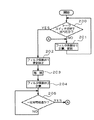
本実施形態の音声入力装置1はこのような構成をしており、次にその動作を説明する。図2は、本実施形態の音声入力装置1に含まれる各フィルタの係数更新手順を示す流れ図である。
【0025】
LMSアルゴリズム処理部26には、車両の走行状態に関係なく、常にトークスイッチ50が利用者によって押下されたか否かを判定する機能も付加されており(ステップ200)、トークスイッチ50が押下されない場合には、演算部28から出力される差分信号Y3のパワーが最小になるように適応フィルタ24のフィルタ係数W1を計算して更新する(ステップ201)。このようにして適応フィルタ24のフィルタ係数W1が設定されるため、周辺雑音の発生源(エンジンやタイヤ等)から一方のマイクロホン10および遅延素子22を経由して演算部28に至るまでの周辺雑音の一方の音響伝達系に対応する伝達特性と、周辺雑音の発生源から他方のマイクロホン12および適応フィルタ24を経由して演算部28に至るまでの周辺雑音の他方の音響伝達系に対応する伝達特性を同じにすることができる。したがって、これら2つの音響伝達系を通って演算部28に到達する周辺雑音は、位相および振幅が同じになるため、演算部28によって2つの入力信号Y1、Y2の差分を求めることにより、この周辺雑音を除去することができる。
【0026】
このようにして行われる周辺雑音の除去動作と並行して上述したステップ200の判定動作(トークスイッチが押下されたか否かの判定動作)が行われており、利用者によってトークスイッチ50が押下されると、次に、LMSアルゴリズム処理部26は、適応フィルタ24のフィルタ係数W1の更新処理を停止し(ステップ202)、その時点で適応フィルタ24に設定されているフィルタ係数W1をフィルタ係数格納部30に格納する(ステップ203)。なお、上述したように、このフィルタ係数格納部30には、あらかじめ求められたスピーカ102から各マイクロホン10、12までの伝達特性CS1、CS2と、遅延素子22の伝達特性Z-mが格納されている。
【0027】
次に、スピーカ音声除去部40内のフィルタ係数計算部44は、フィルタ係数格納部30に格納されているフィルタ係数W1、伝達特性CS1、CS2、Z-mを読み出して、これらに基づいてフィルタ42に設定するフィルタ係数W2を計算する(ステップ204)。
【0028】
ところで、オーディオ機器100の出力信号Xと、周辺雑音除去部20から出力されてスピーカ音声除去部40内の演算部46に入力される信号Y3との関係は、周波数領域で、
Y3=(CS1・Z-m−CS2・W1)X …(1)
と表すことができる。また、オーディオ機器100の出力信号Xと、スピーカ音声除去部40内のフィルタ42から出力されて演算部46に入力される信号Y4との関係は、
Y4=W2・X …(2)
と表すことができる。したがって、W2=CS1・Z-m−CS2・W1を満たすようにフィルタ42のフィルタ係数W2を設定することにより、オーディオ機器100から出力されて周辺雑音除去部20を通って演算部46に入力される信号Y3と、オーディオ機器100から出力されてスピーカ102を介さずに直接フィルタ42を通って演算部46に入力される信号Y4とを同じにすることができ、演算部46の出力信号Y5に含まれるオーディオ音声成分を除去することができる。特に、トークスイッチ50が押下されたときにフィルタ係数W1の更新処理が停止されているため、フィルタ係数W1および伝達特性CS1、CS2、Z-mの全てが既知の値であり、計算によって容易にフィルタ42のフィルタ係数W2を求めることができる。
【0029】
上述した動作は、トークスイッチ50が押下されてから一定時間(例えば数秒間)行われる。LMSアルゴリズム処理部26には、トークスイッチ50が押下されたか否かを判定する部分も内蔵されており(ステップ200)、一定時間が経過すると(ステップ205)、ステップ201に戻ってフィルタ係数W1の計算および更新処理以降の動作を繰り返す。
【0030】
このように、本実施形態の音声入力装置1では、利用者がトークスイッチ50を押下した後にマイクロホン10、12に向かって何らかの操作音声を発声したときに、マイクロホン10、12の出力信号に含まれる周辺雑音成分を前段の周辺雑音除去部20によって除去し、オーディオ機器100から出力されるオーディオ音声成分を後段のスピーカ音声除去部40によって除去しており、これらの各種の雑音が除去された後の操作音声のみが含まれる音声信号が音声認識装置90に入力される。したがって、マイクロホン10、12によって集音された音声に周辺雑音成分やオーディオ音声成分が含まれている場合であっても、これらを除去した操作音声のみが音声認識装置90に送られるため、音声認識装置90において所定の音声認識処理を実行したときの認識率を高めることができる。また、利用者が操作音声を発声する際に、スピーカ102から出力されるオーディオ音声を遮断したり、その音量を小さくした状態で、利用者による操作音声の入力を行うことができ、オーディオ音声を断続させた場合に聴取者が感じる違和感、不快感をなくすことができる。
【0031】
特に、トークスイッチ50が押下される直前まで適応フィルタ24におけるフィルタ係数W1の更新が行われているため、実状に即した周辺雑音の除去を行うことができる。
【0032】
なお、本発明は上記実施形態に限定されるものでなく、本発明の要旨の範囲内で種々の変形実施が可能である。例えば、上述した実施形態では、ナビゲーション装置に対する操作音声を利用者が発声する場合を例にとって説明したが、ナビゲーション装置以外の車載用機器(例えばオーディオ機器)に対する操作音声を利用者が発声する場合にも本発明を適用することができる。また、音声認識の対象となる音声を入力する場合の他に、例えば車室内で移動体電話を用いる場合に、会話に含まれる周辺雑音やオーディオ音声を除去する場合であってもよい。また、車室内で使用される場合の他に、屋内に設置された音声認識装置やその他の装置に対して入力する音声に含まれる周辺雑音成分やスピーカ出力音声(オーディオ音声に限定されず、テレビジョン放送の音声等であってもよい)成分を除去するようにしてもよい。
【0033】
また、上述した実施形態では、2つのマイクロホン10、12を用いたが、3つ以上のマイクロホンを用いるようにしてもよい。また、利用者は、トークスイッチ50を押下した後に操作音声を発声するようにしたが、操作音声の先頭部分を検出する回路を設けて、この検出信号をLMSアルゴリズム処理部26やフィルタ係数計算部44に送るようにしてもよい。
【0034】
【発明の効果】
上述したように、本発明によれば、集音手段から出力される音声信号に含まれる周辺雑音成分を、適応フィルタを用いて除去するとともに、この周辺雑音が除去された後の音声信号からスピーカの出力音成分を除去しており、利用者が発声した音声のみを抽出することができるため、その際にスピーカの音量等を下げる等の操作を行う必要がない。
【図面の簡単な説明】
【図1】本実施形態の音声入力装置の構成を示す図である。
【図2】本実施形態の音声入力装置の動作手順を示す流れ図である。
【符号の説明】
1 音声入力装置
10、12 マイクロホン
20 周辺雑音除去部
22 遅延素子
24 適応フィルタ
26 LMSアルゴリズム処理部
28、46 演算部
30 フィルタ係数格納部
40 スピーカ音声除去部
42 フィルタ
44 フィルタ係数計算部
50 トークスイッチ
90 音声認識装置
100 オーディオ機器
102 スピーカ[0001]
BACKGROUND OF THE INVENTION
The present invention relates to a voice input system that removes various types of noise from voice collected by a microphone.
[0002]
[Prior art]
As a method of giving various operation instructions to recent in-vehicle devices, such as navigation devices and audio devices, in addition to the method in which the user presses various keys on the operation panel or remote control (remote control) unit, it can be used. There is a method of recognizing the contents of operation voices uttered by a person. When operating instructions using the voice recognition device, it is not necessary to remember the operation key layout, etc., and it is not necessary to operate the keys when the vehicle vibrates while traveling, which simplifies the operation. This is possible, and in recent years, it is often used for in-vehicle devices as the processor speeds up.
[0003]
Typical factors that reduce the recognition rate by such a speech recognition device include vehicle interior vehicle noise caused by traveling such as road noise and engine noise, and audio sound output from an audio device in the vehicle interior. There is. When these noises and audio sounds are superimposed on the user's voice, the voice recognition device cannot distinguish between them and perform voice recognition processing only on the user's voice. It becomes difficult. For this reason, conventionally, an adaptive microphone array technology is used to reduce road noise, or when the talk switch is pressed, the output of the audio sound is interrupted or the volume is reduced, and the audio signal that is subject to speech recognition. The device is designed to reduce various noises and audio sounds superimposed on the sound.
[0004]
[Problems to be solved by the invention]
By the way, if the audio sound output is interrupted when the talk switch is pressed as described above, or if the measures are taken by lowering the volume of the audio sound, the audio sound will not be output when the voice recognition processing is frequently performed. Since this is intermittent, there is a problem that the listening by the user is hindered.
[0005]
In particular, passengers other than users who operate in-vehicle devices by voice input may be listening to audio sound regardless of this operation, so the audio sound being listened to is frequently intermittent. Therefore, there is a demand for a technique that can extract the input voice without interrupting the generated sound other than the input voice to be recognized.
[0006]
The present invention was created in view of the above points, and an object of the present invention is to provide a voice input system that can extract input voice without interrupting generated sounds other than the input voice. .
[0007]
[Means for Solving the Problems]
In order to solve the above-described problem, an audio input device of the present invention includes an ambient noise removing unit that removes an ambient noise component included in an audio signal output from the sound collecting unit using an adaptive filter, and the ambient noise. Speaker removal means for removing the output component of the speaker from the audio signal after the noise is removed, and the peripheral noise component and the speaker sound component (for example, audio sound output from the speaker) are removed from the audio signal. Thus, only the voice uttered by the user can be extracted, and there is no need to perform an operation such as lowering the volume of the speaker.
[0008]
Specifically, the sound collecting means described above includes first and second microphones, and the ambient noise removing means converts the noise signal output from the first microphone to the noise output from the second microphone. It has an adaptive filter that is simulated by a signal, and a first calculation means for calculating the difference between these two noise signals. By using the adaptive filter, the noise signals output from the two microphones can be matched, so by calculating the difference between these two signals, the ambient noise component can be canceled. The removed audio signal can be obtained.
[0009]
The speaker sound removing means described above calculates a difference between a filter that simulates the characteristics of the transmission system via the speaker and the ambient noise removing means, and a signal that passes through the ambient noise removing means and a signal that passes through the filter. 2 arithmetic means. Since the characteristics of the transmission system such as audio sound output from the speaker are simulated by the filter, a signal equivalent to the signal corresponding to the sound actually output from the speaker can be generated by the filter. The sound component can be canceled, and an audio signal from which the output sound component has been removed can be obtained.
[0010]
In addition, when the timing of voice input to the sound collecting means is instructed, the update operation of the filter coefficient of the adaptive filter is stopped, and the filter coefficient of the filter is set based on the filter coefficient of the adaptive filter for which the update operation is stopped. It is preferable to calculate. When the filter coefficient of the adaptive filter is fixed, the characteristic of the acoustic transmission system via the ambient noise removing means is fixed. Therefore, the filter coefficient of the filter that simulates this characteristic can be obtained by calculation.
[0011]
DETAILED DESCRIPTION OF THE INVENTION
Hereinafter, a voice input device according to an embodiment to which the present invention is applied will be described with reference to the drawings.
FIG. 1 is a diagram illustrating a configuration of a voice input device according to the present embodiment. The voice input device 1 of the present embodiment shown in the figure includes two
[0012]
The
[0013]
The ambient
[0014]
The
[0015]
The
[0016]
The LMS
[0017]
The
[0018]
The filter
[0019]
Further, the speaker sound removal unit 40 shown in FIG. 1 is for removing the audio sound included in the output signal Y3 of the ambient
[0020]
The
[0021]
The
[0022]
Further, the
[0023]
The
[0024]
The voice input device 1 of the present embodiment has such a configuration, and the operation thereof will be described next. FIG. 2 is a flowchart showing the coefficient update procedure of each filter included in the voice input device 1 of the present embodiment.
[0025]
The LMS
[0026]
In parallel with the removal operation of ambient noise performed in this way, the determination operation of
[0027]
Next, the filter
[0028]
By the way, the relationship between the output signal X of the
Y3 = (CS1 · Z− m− CS2 · W1) X (1)
It can be expressed as. The relationship between the output signal X of the
Y4 = W2 · X (2)
It can be expressed as. Therefore, by setting the filter coefficient W2 of the
[0029]
The above-described operation is performed for a certain time (for example, several seconds) after the
[0030]
As described above, in the voice input device 1 according to the present embodiment, when the user utters some operation voice toward the
[0031]
In particular, since the filter coefficient W1 in the
[0032]
In addition, this invention is not limited to the said embodiment, A various deformation | transformation implementation is possible within the range of the summary of this invention. For example, in the above-described embodiment, the case where the user utters the operation sound for the navigation device has been described as an example. The present invention can also be applied. Moreover, in addition to the case where a voice to be subjected to voice recognition is input, for example, when a mobile phone is used in a vehicle interior, it may be a case where ambient noise and audio voice included in the conversation are removed. Moreover, in addition to the case where it is used in a vehicle interior, ambient noise components and speaker output sound (not limited to audio sound, which are included in sound input to a voice recognition device installed indoors or other devices, are not limited to audio sound. (This may be the sound of John Broadcast, etc.) The component may be removed.
[0033]
In the embodiment described above, the two
[0034]
【The invention's effect】
As described above, according to the present invention, the ambient noise component included in the audio signal output from the sound collecting means is removed using the adaptive filter, and the speaker is removed from the audio signal after the ambient noise is removed. Therefore, it is not necessary to perform operations such as lowering the volume of the speaker at that time.
[Brief description of the drawings]
FIG. 1 is a diagram illustrating a configuration of a voice input device according to an embodiment.
FIG. 2 is a flowchart showing an operation procedure of the voice input device according to the embodiment.
[Explanation of symbols]
DESCRIPTION OF SYMBOLS 1
Claims (2)
前記集音手段は、第1および第2のマイクロホンを有し、
前記周辺雑音除去手段は、前記第1のマイクロホンから出力されるノイズ信号を前記第2のマイクロホンから出力されるノイズ信号を用いて模擬する前記適応フィルタと、これら2つのノイズ信号の差分を計算する第1の演算手段と、前記適応フィルタのフィルタ係数の更新処理を行うとともに、前記入力タイミング指示手段によって前記音声入力のタイミングが指示されたときに、前記適応フィルタのフィルタ係数の更新動作を停止するフィルタ処理手段と、前記第1のマイクロホンと前記第1の演算手段との間に挿入されて伝達特性Z -m で表される遅延素子とを有し、
前記スピーカ音声除去手段は、前記スピーカおよび前記周辺雑音除去手段を介した伝達系の特性を模擬するフィルタと、前記周辺雑音除去手段を介した信号と前記フィルタを介した信号との差分を計算する第2の演算手段と、前記入力タイミング指示手段によって前記音声入力のタイミングが指示されたときに、前記スピーカから前記第1および第2のマイクロホンのそれぞれまでの伝達特性CS1、CS2、更新動作が停止された前記適応フィルタのフィルタ係数W1を用いて、W2=CS1・Z -m −CS2・W1となるように前記フィルタのフィルタ係数W2を設定するフィルタ係数計算手段とを有することを特徴とする音声入力装置。A peripheral noise removing unit that removes an ambient noise component included in an audio signal output from the sound collecting unit using an adaptive filter, and an output of a speaker from the audio signal after the ambient noise is removed by the ambient noise removing unit In a voice input device comprising: speaker voice removing means for removing a component; and input timing instruction means for instructing voice input timing to the sound collecting means;
The sound collecting means has first and second microphones,
The ambient noise removing unit calculates the difference between the adaptive filter that simulates the noise signal output from the first microphone using the noise signal output from the second microphone, and the difference between the two noise signals. Update processing of the filter coefficient of the adaptive filter is performed, and when the timing of the voice input is instructed by the input timing instruction means, the update operation of the filter coefficient of the adaptive filter is stopped. Filter processing means, and a delay element inserted between the first microphone and the first arithmetic means and represented by a transfer characteristic Z -m ,
The speaker sound removal means calculates a difference between a filter that simulates the characteristics of a transmission system via the speaker and the ambient noise removal means, and a signal that passes through the ambient noise removal means and a signal that passes through the filter. When the timing of the voice input is instructed by the second arithmetic means and the input timing instruction means, the transfer characteristics CS1, CS2, and the updating operation from the speaker to the first and second microphones are stopped. And a filter coefficient calculating means for setting the filter coefficient W2 of the filter such that W2 = CS1 · Z −m −CS2 · W1 using the filter coefficient W1 of the adaptive filter. Input device.
前記入力タイミング指示手段によって前記音声入力のタイミングが指示されて前記適応フィルタのフィルタ係数の更新動作が停止されたときに、このフィルタ係数を格納するフィルタ係数格納部をさらに備え、
前記フィルタ係数計算手段は、前記フィルタ係数格納部に格納されたフィルタ係数を用いて、前記フィルタのフィルタ係数の計算を行うことを特徴とする音声入力装置。 In claim 1 ,
A filter coefficient storage unit for storing the filter coefficient when the input timing instruction means instructs the voice input timing and the filter coefficient update operation of the adaptive filter is stopped;
The voice input device, wherein the filter coefficient calculation means calculates the filter coefficient of the filter using the filter coefficient stored in the filter coefficient storage unit.
Priority Applications (2)
| Application Number | Priority Date | Filing Date | Title |
|---|---|---|---|
| JP33845498A JP3774580B2 (en) | 1998-11-12 | 1998-11-12 | Voice input device |
| US09/438,447 US6847723B1 (en) | 1998-11-12 | 1999-11-12 | Voice input apparatus |
Applications Claiming Priority (1)
| Application Number | Priority Date | Filing Date | Title |
|---|---|---|---|
| JP33845498A JP3774580B2 (en) | 1998-11-12 | 1998-11-12 | Voice input device |
Publications (2)
| Publication Number | Publication Date |
|---|---|
| JP2000148200A JP2000148200A (en) | 2000-05-26 |
| JP3774580B2 true JP3774580B2 (en) | 2006-05-17 |
Family
ID=18318321
Family Applications (1)
| Application Number | Title | Priority Date | Filing Date |
|---|---|---|---|
| JP33845498A Expired - Fee Related JP3774580B2 (en) | 1998-11-12 | 1998-11-12 | Voice input device |
Country Status (2)
| Country | Link |
|---|---|
| US (1) | US6847723B1 (en) |
| JP (1) | JP3774580B2 (en) |
Families Citing this family (10)
| Publication number | Priority date | Publication date | Assignee | Title |
|---|---|---|---|---|
| JP4226395B2 (en) * | 2003-06-16 | 2009-02-18 | アルパイン株式会社 | Audio correction device |
| JP4235128B2 (en) * | 2004-03-08 | 2009-03-11 | アルパイン株式会社 | Input sound processor |
| JP4578426B2 (en) * | 2006-03-28 | 2010-11-10 | アルパイン株式会社 | Audio sound cancellation system |
| JP4506873B2 (en) * | 2008-05-08 | 2010-07-21 | ソニー株式会社 | Signal processing apparatus and signal processing method |
| US9082391B2 (en) * | 2010-04-12 | 2015-07-14 | Telefonaktiebolaget L M Ericsson (Publ) | Method and arrangement for noise cancellation in a speech encoder |
| KR101500823B1 (en) | 2010-11-25 | 2015-03-09 | 고어텍 인크 | Method and device for speech enhancement, and communication headphones with noise reduction |
| CN103940417A (en) * | 2014-04-04 | 2014-07-23 | 广东翼卡车联网服务有限公司 | Navigation method and system for improving data transmission by wavelet transform |
| KR101619260B1 (en) * | 2014-11-10 | 2016-05-10 | 현대자동차 주식회사 | Voice recognition device and method in vehicle |
| JP6948609B2 (en) * | 2018-03-30 | 2021-10-13 | パナソニックIpマネジメント株式会社 | Noise reduction device |
| KR20230053630A (en) * | 2020-09-21 | 2023-04-21 | 엘지전자 주식회사 | Control device and system including the same |
Family Cites Families (5)
| Publication number | Priority date | Publication date | Assignee | Title |
|---|---|---|---|---|
| US5251263A (en) * | 1992-05-22 | 1993-10-05 | Andrea Electronics Corporation | Adaptive noise cancellation and speech enhancement system and apparatus therefor |
| US5402496A (en) | 1992-07-13 | 1995-03-28 | Minnesota Mining And Manufacturing Company | Auditory prosthesis, noise suppression apparatus and feedback suppression apparatus having focused adaptive filtering |
| JPH0720884A (en) * | 1993-07-01 | 1995-01-24 | Fuji Heavy Ind Ltd | Intra-cabin noise reducing device |
| DE69631955T2 (en) * | 1995-12-15 | 2005-01-05 | Koninklijke Philips Electronics N.V. | METHOD AND CIRCUIT FOR ADAPTIVE NOISE REDUCTION AND TRANSMITTER RECEIVER |
| US5796819A (en) * | 1996-07-24 | 1998-08-18 | Ericsson Inc. | Echo canceller for non-linear circuits |
-
1998
- 1998-11-12 JP JP33845498A patent/JP3774580B2/en not_active Expired - Fee Related
-
1999
- 1999-11-12 US US09/438,447 patent/US6847723B1/en not_active Expired - Lifetime
Also Published As
| Publication number | Publication date |
|---|---|
| JP2000148200A (en) | 2000-05-26 |
| US6847723B1 (en) | 2005-01-25 |
Similar Documents
| Publication | Publication Date | Title |
|---|---|---|
| JP3774580B2 (en) | Voice input device | |
| JP2012025270A (en) | Apparatus for controlling sound volume for vehicle, and program for the same | |
| KR102663259B1 (en) | Active noise control using feedback compensation | |
| CN113066468A (en) | Active noise interference elimination optimization device and method based on in-vehicle environment | |
| JP2007180896A (en) | Voice signal processor and voice signal processing method | |
| JP2004333704A (en) | Apparatus and method for speech recognition | |
| JP2002051392A (en) | In-vehicle conversation assisting device | |
| JP2007264436A (en) | Sound masking device, sound masking method, and program | |
| JP2894035B2 (en) | Active noise control device | |
| US7542577B2 (en) | Input sound processor | |
| JP2008070878A (en) | Voice signal pre-processing device, voice signal processing device, voice signal pre-processing method and program for voice signal pre-processing | |
| JP2010141468A (en) | Onboard acoustic apparatus | |
| JP3822397B2 (en) | Voice input / output system | |
| JP5383008B2 (en) | Speech intelligibility improvement system and speech intelligibility improvement method | |
| JP2008070877A (en) | Voice signal pre-processing device, voice signal processing device, voice signal pre-processing method and program for voice signal pre-processing | |
| JP2002514775A (en) | Method and apparatus for operating voice assist system in vehicle | |
| JPH05207117A (en) | Directional controller for microphone | |
| JP6632246B2 (en) | Noise reduction device, noise reduction method, and in-vehicle system | |
| JP2001236090A (en) | Voice input device | |
| JP2002171587A (en) | Sound volume regulator for on-vehicle acoustic device and sound recognition device using it | |
| JP4162860B2 (en) | Unnecessary sound signal removal device | |
| JP3046101B2 (en) | Active noise control device | |
| JP3796869B2 (en) | Active noise reduction apparatus and noise reduction method | |
| JP2007143008A (en) | Sound pickup switching apparatus and sound pickup switching method | |
| JP2000132200A (en) | Audio/video device with voice recognizing function and voice recognizing method |
Legal Events
| Date | Code | Title | Description |
|---|---|---|---|
| A977 | Report on retrieval |
Free format text: JAPANESE INTERMEDIATE CODE: A971007 Effective date: 20050502 |
|
| A131 | Notification of reasons for refusal |
Free format text: JAPANESE INTERMEDIATE CODE: A131 Effective date: 20050524 |
|
| A521 | Request for written amendment filed |
Free format text: JAPANESE INTERMEDIATE CODE: A523 Effective date: 20050719 |
|
| A02 | Decision of refusal |
Free format text: JAPANESE INTERMEDIATE CODE: A02 Effective date: 20051011 |
|
| A521 | Request for written amendment filed |
Free format text: JAPANESE INTERMEDIATE CODE: A523 Effective date: 20051110 |
|
| A911 | Transfer to examiner for re-examination before appeal (zenchi) |
Free format text: JAPANESE INTERMEDIATE CODE: A911 Effective date: 20051222 |
|
| TRDD | Decision of grant or rejection written | ||
| A01 | Written decision to grant a patent or to grant a registration (utility model) |
Free format text: JAPANESE INTERMEDIATE CODE: A01 Effective date: 20060214 |
|
| A61 | First payment of annual fees (during grant procedure) |
Free format text: JAPANESE INTERMEDIATE CODE: A61 Effective date: 20060220 |
|
| R150 | Certificate of patent or registration of utility model |
Free format text: JAPANESE INTERMEDIATE CODE: R150 |
|
| FPAY | Renewal fee payment (event date is renewal date of database) |
Free format text: PAYMENT UNTIL: 20100224 Year of fee payment: 4 |
|
| FPAY | Renewal fee payment (event date is renewal date of database) |
Free format text: PAYMENT UNTIL: 20100224 Year of fee payment: 4 |
|
| FPAY | Renewal fee payment (event date is renewal date of database) |
Free format text: PAYMENT UNTIL: 20110224 Year of fee payment: 5 |
|
| FPAY | Renewal fee payment (event date is renewal date of database) |
Free format text: PAYMENT UNTIL: 20110224 Year of fee payment: 5 |
|
| FPAY | Renewal fee payment (event date is renewal date of database) |
Free format text: PAYMENT UNTIL: 20120224 Year of fee payment: 6 |
|
| FPAY | Renewal fee payment (event date is renewal date of database) |
Free format text: PAYMENT UNTIL: 20120224 Year of fee payment: 6 |
|
| FPAY | Renewal fee payment (event date is renewal date of database) |
Free format text: PAYMENT UNTIL: 20130224 Year of fee payment: 7 |
|
| FPAY | Renewal fee payment (event date is renewal date of database) |
Free format text: PAYMENT UNTIL: 20130224 Year of fee payment: 7 |
|
| FPAY | Renewal fee payment (event date is renewal date of database) |
Free format text: PAYMENT UNTIL: 20140224 Year of fee payment: 8 |
|
| LAPS | Cancellation because of no payment of annual fees |