JP3774501B2 - Magnetic marker and reading method thereof - Google Patents
Magnetic marker and reading method thereof Download PDFInfo
- Publication number
- JP3774501B2 JP3774501B2 JP04170496A JP4170496A JP3774501B2 JP 3774501 B2 JP3774501 B2 JP 3774501B2 JP 04170496 A JP04170496 A JP 04170496A JP 4170496 A JP4170496 A JP 4170496A JP 3774501 B2 JP3774501 B2 JP 3774501B2
- Authority
- JP
- Japan
- Prior art keywords
- magnetic
- scanning direction
- recording medium
- marker
- pattern
- Prior art date
- Legal status (The legal status is an assumption and is not a legal conclusion. Google has not performed a legal analysis and makes no representation as to the accuracy of the status listed.)
- Expired - Fee Related
Links
Images


Landscapes
- Magnetic Record Carriers (AREA)
- Recording Or Reproducing By Magnetic Means (AREA)
- Credit Cards Or The Like (AREA)
Description
【0001】
【発明の属する技術分野】
本発明は、記録媒体の表面に形成された磁気パターンからなる磁気マーカに関し、特に、非接触で読み取ることが可能であって、磁気パターンに多くの情報を持たせた磁気マーカおよびその読取方法に関する。
【0002】
【従来の技術】
近年、磁気パターンからなる磁気マーカに多くの情報が記録された記録媒体が広く普及しつつある。このような記録媒体には、例えば、磁気カードや、磁気切符、磁気定期券、磁気回数券、磁気シートなどがある。かかる磁気マーカは、その媒体に関する種々の情報を示すものであり、光学式バーコードを用いた方式と比べると、泥等の汚れに強いことから、FAや、物流等の分野への利用も図られている。
【0003】
このような記録媒体のうち、例えば、磁気カードは、通常、厚さ100〜200μm程度の非磁性基板上に、厚さ10〜15μm程度の磁気記録層を塗布などすることにより形成され、さらに、磁気記録層から表面保護層までは、磁気マーカとして、磁気によるバーコードが設けられる層や、隠蔽層、感熱印字層などの各層が積層される。これら各層の層数、層の種類等は、磁気カードに要求される出力や、特性等に適するように設定される。
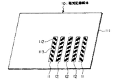
ここで、バーコードは、磁気記録層において、磁性体が含有された磁性部分と、磁性体が含有されていない非磁性部分との組み合わせにより構成され、カードに固定情報(たとえば、使用者IDや、金額、発行機関などに関するパターン情報)を持たせている。これにより、記録媒体においてはセキュリティが確保されている。このようなバーコードBCは、磁気カードの表面上に対し、例えば図11に示すような位置で形成される。なお、図においては、説明の便宜上、バーコードBCにおける磁性部分および非磁性部分の両者を図示したが、実際には、後述するようにマグネットビュワー等を用いない限り、肉眼で判別することはできない。
【0004】
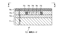
図12は、図11のA−A’線の拡大断面図である。この図に示すように、磁気カード70は、非磁性の基板71の上に磁気記録層72が形成され、ここに、磁気記録層72に使用されている磁性体よりも低保磁力の磁性粉からなる磁気バーコード部73と、非磁性粉からなるダミーバーコード部74とが、オフセット印刷や、スクリーン印刷等により形成される。さらに、一般の磁気カードにおいて、これら磁性・非磁性のバーコード部を隠蔽する隠蔽層75や、表面を保護するための保護層76等が、同様な印刷等により形成される。
【0005】
ところで、この種の磁気カードにおいては、磁気バーコード部73を構成する磁気材料として、従来より主に2タイプが使用されており、このため、その読み取り方法も次のように異なっていた。
すなわち、第1のタイプは、磁気バーコード部73を、磁気記録層72の保磁力に影響を与えない程度の保磁力であって、かつ、記録も十分に行なえる保磁力を有する磁性材料を用いて形成した後、磁気記録層に用いるのと同様な方法で、記録の書込・読取を行なうものである。この場合に用いられる磁性材料としては、例えば、マグネタイト(Fe3O4)や、γ酸化鉄(γ−Fe2O3)等が考えられる。
しかしながら、この第1のタイプでは、磁気記録された磁気バーコード部73は、一般に市販されている、いわゆるマグネットビュワー等を用いると、磁気バーコード部73とダミーバーコード部74とを見極めることができてしまう。これを防止するためには、磁気バーコード部73に記録された情報を読み取った後、消磁するなどの策を講じる必要があるが、読取にかかる構成が複雑かつ肥大する、という欠点があった。
【0006】
そこで、このような問題を解決するために、案出されたのが、次に説明する第2のタイプである。すなわち、かかる第2のタイプは、磁気バーコード部73の磁性材料として、マグネットビュワー等で感知されないような、保磁力が30Oe以下の低保磁力を有するカルボニル鉄粉や、Mn−Znフェライト等を用いたものである(例えば、特開平1−109524号公報参照)。
【0007】
そして、第2のタイプにより形成された磁気バーコード部73は、次のような方法で読み取られる。
すなわち、まず、読取用磁気ヘッドにバイアスとして直流電流を流し、磁気バーコード部73に、磁気記録に影響を与えない程度の弱い直流磁界を印加する。すると、かかる直流磁界によって、低保磁力の磁性材料により形成された磁気バーコード部73は磁化され、これを読取用磁気ヘッドで同時に読み込むことで、図13に示すような出力信号波形を得る。この場合において、ダミーバーコード部74は磁化されないので、これに対応する出力はない。したがって、磁気バーコード部73とダミーバーコード部74との組み合わせにより、特定パターンにかかる出力信号波形を得ることができ、この波形を後段の解析回路によって解析することで、特定パターンで符号化された情報を得ることができる。
【0008】
また、上記第1および第2のタイプ以外でも、セキュリティを確保するために、保磁力の異なる磁性材料を組み合わせた方法(例えば特開昭63−133321号公報や、特開昭63−308724号公報参照)や、磁化量の異なる磁気バーコードを組み合わせた方法(例えば特開昭63−223892号公報参照)、キュリー点の異なる磁性体を用いた方法(例えば実開昭62−147191号公報参照)など、種々の方法がある。これらの方法によるバーコードが示す情報は、通常の磁気記録方法とは異なる固定情報であり、一般に磁気カード上に磁気バーコードを設けるのは、セキュリティの確保にほかならない。
【0009】
一方、磁気マーカは、カードに用いる用途以外でも実用化されている(例えば特開平1−233675号公報や、特開平1−233688号公報参照)。このような磁気マーカからなるバーコードは、棒状金属の配列によりデータを記録するものであり、直流磁界を発生させる永久磁石と、磁束量を検出するMR(磁気抵抗)センサとによって、磁気マーカを非接触で読み取ることができる。これにより、磁気マーカが泥等により汚れても十分機能するので、一般的な光学式バーコードを用いた場合の欠点が解消された。
【0010】
このように、現在数多くの磁気マーカが用いられ、その大部分が磁気バーコードとして利用されている。
【0011】
【発明が解決しようとする課題】
しかしながら、従来の磁気マーカは、接触式で読み取る方法がほとんどであるため、磁気マーカにゴミの付着や汚れ等などが発生すると、その読取性能が悪化する、といった欠点を有していた。また、MRセンサにより非接触で読み取るにしても、結局は磁束の有無と符号の2値とを対応させているに過ぎないため、記録可能な情報量は極めて少ない、という欠点があった。
本発明は、上述した背景に鑑みてなされたもので、その目的とするところは、非接触で読取が可能であって、かつ、記録可能な情報量を多くすることが可能な磁気マーカおよびその読取方法を提供することにある。
【0012】
【課題を解決するための手段】
上記課題を解決するため、請求項1に記載の発明にあっては、磁化容易方向が走査方向に対して所定の角度をなすように形成された磁気パターンからなる磁気マーカであって、前記角度により符号化が行なわれ、前記磁気パターンは、1つの符号に対し、走査方向とは略垂直方向に複数列形成されていることを特徴としている。
請求項2に記載の発明にあっては、請求項1に記載の発明において、導体基板に略平行四辺形形状の孔を前記走査方向とは所定の角度をなして形成した後、前記導体基板に磁性板を貼着して、前記磁気パターンとしたことを特徴としている。
請求項3に記載の発明にあっては、請求項1に記載の発明において、基板に、磁性材からなるワイヤを、前記走査方向とは所定の角度をなして並べて、前記磁気パターンとしたことを特徴としている。
さらに、請求項4に記載の発明にあっては、磁気マーカの読取方法であって、磁化容易方向が走査方向とは所定の角度をなすように形成された磁気パターンを磁気励起する過程と、磁気励起された磁束のうち、前記磁気パターンによって曲げられた成分であって、前記走査方向とは同方向あるいは逆方向の成分によって誘導起電力を生じさせる過程と、前記誘導起電力により符号の取得を行なう過程とを備えることを特徴としている。
【0013】
【発明の実施の形態】
以下、本発明による実施の形態について、図面を参照して説明する。
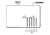
図1は、この実施形態の磁気マーカを適用した磁気記録媒体の構成を示す平面図である。この図に示す磁気記録媒体10には、その上面に、磁気パターン11、12の5本からなるバーコードBC、すなわち磁気マーカが形成される。かかる磁気パターン11および12は、それぞれ符号の「0」、「1」に対応するものであり、高透磁率を有する磁性体小片の多数配列により構成されるものである。各磁性体小片のストリップ方向(磁化容易方向)と走査方向となす角度は、図において時計回りを正とした場合、磁気パターン11については+45度であり、磁気パターン12については−45度となっている。
【0014】
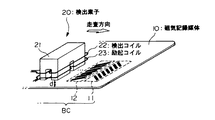
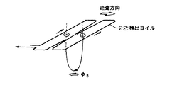
次に、上述した磁気記録媒体10に形成されたバーコードBCを読み取るための構成について図2を参照して説明する。この図に示すように、読取時において磁気記録媒体10は、検出素子20により間隔dを置いて非接触で走査され、その際、バーコードBCが読み取られる。この場合、磁気記録媒体10が搬送されて、固定された検出素子20が読み取る構成としても、反対に、磁気記録媒体10を固定として、検出素子20が走査する構成としても良い。すなわち、磁気記録媒体10と検出素子20とにおいて、図に示す走査方向の相対移動が発生すれば、本実施形態では、いずれの構成でもよい。
【0015】
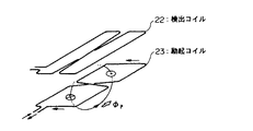
ここで、検出素子20は、図に示すように、コア21、検出コイル22および励起コイル23から構成される。検出コイル22および励起コイル23は、図3に示すように、それぞれ矩形8字状に形成されるものであり、互いに直交し、図では説明のため離れているが、その形成平面は略同一である。
なお、検出コイル22の検出磁束および励起コイル23の発生磁束をそれぞれ高めるため、図2に示すようにコア21には十字状の溝が形成され、かかる溝により形成される突起部分に検出コイル22および励起コイル23がそれぞれ巻回されるとともに、コア21の材質にはフェライトなど高透磁率磁性体が用いられる。また、検出コイル22および励起コイル23は、図では説明のため、1ターンであるが、やはり磁束を高めるため、通常では複数ターンである。
【0016】
次に、かかる読取構成において、いかにしてバーコードBCの情報が得られるかについて説明する。
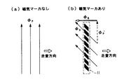
はじめに、励起コイル23に対し、図3に示した方向に電流を流したとすると、この電流で発生する磁界により、励起コイル23の下面には、図に示すような磁束φPが発生する。この際、磁気記録媒体10の上面において磁気マーカが形成されていない箇所では、同一の磁束φPが、磁気記録媒体10を上からみると図4(a)に示すように、走査方向と垂直方向に発生する。
これに対し、例えば、磁気パターン11が形成されている箇所では、図4(b)に示すように、発生磁界が磁気パターン11のストリップ方向にしたがって曲げられ、この曲げ磁界にかかる磁束φAが発生する。かかる磁束φAは、走査方向とは垂直方向に成分を有する磁束φP’と、走査方向とは逆方向の成分を有する磁束φBとに分解することができる。このため、走査方向に成分を有する磁束が、励起コイル23による磁気励起によって新たに発生することになる。一方、磁気パターン12が形成されている箇所では、同様な理由から、磁束φBとは逆向き磁束が生じる。
なお、磁気マーカが形成されていない箇所では、磁束φPが走査方向とは垂直方向に直進するため(図4(a)参照)、走査方向に成分を有する磁束は生じない。
【0017】
さて、磁気パターン11によって磁束φBが発生すると、この磁束φBによって、図5に示すように、走査方向とは垂直方向に磁界が発生し、なおかつ、この磁界に対し検出コイル22が走査方向に相対移動しているので、検出コイル22には、誘導起電力が同図に示す方向に生じる。また、磁気パターン12については、磁界の向きが同図に示す方向と反対となるので、逆向きの誘導起電力が生じる。
なお、磁気マーカが形成されていない箇所では、励起コイル23による磁界によっては、走査方向成分を有する磁束が存在しないため、検出コイル22に誘導起電力が生じない。
【0018】
したがって、励起コイル23に電流を流し、検出素子20を磁気記録媒体10に対し相対移動させて、検出コイル22に発生する誘導起電力の有無、さらに有のときには、その電圧(および極性)を検出することにより、バーコードBCに対応する情報を取得することができる。
【0019】
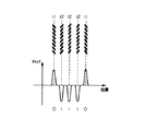
ところで、励起コイル22に直流電流を流し続けることは、周辺部の着磁現象を招くので好ましくなく、また、出力電圧も小さい。そこで、本実施形態にあっては、励起コイル22に交流電流を励起信号とし、これにより交流磁界を発生させることとしている。このような構成例を図6に示す。この例では、励起信号の周波数を100kHzとし、ロックインアンプ30によって、検出コイル22の出力を、励起信号と同期して整流した電圧Voutを得ることとしている。
【0020】
かかる出力電圧Voutと検出素子20の位置との関係を図7に示す。この図に示すように、励起コイル23に交流を流す構成としても、Vout信号の有無、さらに有のときには、その極性を検出することにより、バーコードBCに対応する情報を得ることができる。この図に示す例では、磁気パターン11、12、12、12、11に対応する電圧Voutによって、符号「0」、「1」、「1」、「1」、「0」を取得することができるのである。
【0021】
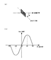
さて、上述した実施形態において、磁気マーカを構成する磁性体のストリップ方向は、検出素子20の走査方向に対して+45度および−45度に設定した。ここで、図8(a)において、走査方向に対する磁性体ストリップの方向の角度θを、−90度から+90度まで変化させた場合における電圧Voutの特性を同図(b)に示す。この図に示すように、出力電圧Voutは、角度θが+45度および−45度のとき最大となる。このため、本実施形態においても、角度θを、磁気パターン11、12についてそれぞれ+45度、−45度と設定したのである。
【0022】
また、逆に言えば、図8(b)をみても判るように、角度θが変化すると、電圧Voutも連続的に変化する。特に、−45≦θ≦45では、電圧Voutが定まれば、角度θも一義的に定まる。このため、角度θと電圧Voutとの対応付けを予め行なうことにより、符号「0」、「1」のディジタルデータのみならず、連続的なアナログデータや、多値のデータも取り扱うことが可能となる。
例えば、角度θが−45度、−30度、+30度および+45度を、それぞれ符号の「00」、「01」、「10」および「11」に対応させる。ここで、角度θが+45度のときの電圧Voutを正規化して「1」とした場合、出力された電圧Voutが「−1」、「−0.5」、「0.5」および「+1」のときに、符号の「00」、「01」、「10」および「11」とすることで、1つバーに対して2ビットの情報を割り当てることができる。
【0023】
したがって、このような磁気マーカによれば、非接触で読み取ることのみならず、1本のバーでアナログデータや、多値データも示すことができる。このため、記録可能な情報量を飛躍的に増加させることが可能となる。
【0024】
くわえて、本実施形態にかかる磁気マーカにおいては、読み取りの際の励起磁化を交流としたことによって、バーコードの幅が符号に対応した従来のバーコードシステムと比べて、走査速度に依存しないで、安定してバーコードを読み取ることができる。
【0025】
【実施例】
次に、磁気記録媒体の具体的な実施例のいくつかについて説明する。
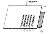
はじめに、第1の実施例について説明する。図9は、この実施例に係る磁気記録媒体の構成を示す斜視図である。この実施例に係る磁気記録媒体10は、次のようにして形成される。まず、基板となる厚さ50μmの銅箔101に対し、磁気パターン11、12の磁性体ストリップに相当する孔をエッチングにより形成する。次に、かかる銅箔101の背面に、厚さ25μmのアモルファスリボン102を接着して磁気記録媒体10とする。すなわち、この実施例は、背面に接着されたアモルファスリボン102を磁気パターン11、12における磁性体小片の1つとして作用させるものである。
この実施例によれば、非磁性導体板の銅箔101と高透磁率磁性体のアモルファスリボン102とにおける透磁率の差が顕著となるため、出力電圧Voutを極めて高くすることができる。
【0026】
次に、第2の実施例について説明する。図10は、この実施例に係る磁気記録媒体の構成を示す斜視図である。この実施例に係る磁気記録媒体10は、次のようにして形成される。まず、直径30μm程度のアモルファスワイヤ112を6本、それぞれ+45度あるいは−45度傾け平行に並べて粘着シート113に貼着させ、1本のバー(磁気マーカ)とする。これを、5本並べて基板となるPET(ポリエチレンテレフタレート)111に貼着させて、磁気記録媒体10とする。すなわち、この実施例は、貼着されたアモルファスワイヤの6本により磁気パターン11、12を構成させ、アモルファスワイヤの1本1本を磁性体小片の1つとして作用させるものである。
【0027】
いずれの実施例においても、磁性材料が、基板上に走査方向とは略垂直方向に複数列平行に形成され、かつ、走査方向に複数行形成される。この際、磁性材料のストリップ方向と走査方向とのなす角度は、記録すべき符号に対応して、−45度あるいは+45度に設定される。
また、1本のバーに多値あるいはアナログデータを対応させる場合には、−45度〜+45度の範囲の角度と多値あるいはアナログデータとの対応を予め定めておき、磁性材料のストリップ方向と走査方向とのなす角度を設定する必要がある。
【0028】
【発明の効果】
以上説明したように、本発明によれば、非接触で読取が可能であって、かつ、記録可能な情報量を多くすることが可能な磁気マーカおよびその読取方法を提供することが可能となる。
【図面の簡単な説明】
【図1】 本発明の実施形態に係る磁気記録媒体の構成を示す平面図である。
【図2】 同磁気記録媒体を読み取るための構成を示す斜視図である。
【図3】 同磁気記録媒体を読み取るための構成における励起コイルおよび検出コイルの構成を示す斜視図であって、読取原理を示すための図である。
【図4】 (a)、(b)は、それぞれ同磁気記録媒体の読取原理を示すための図である。
【図5】 同磁気記録媒体における読取原理を示すための図である。
【図6】 同磁気記録媒体を読み取るための電気的構成を示すブロック図である。
【図7】 同電気的構成における出力信号と、磁気パターンの位置関係とを示す特性図である。
【図8】 (a)は走査方向に対する磁性体小片の位置関係を示す図であり、(b)は同電気的構成における出力電圧と磁性体小片が走査方向となす角度との関係を示す特性図である。
【図9】 本発明の第1実施例に係る磁気記録媒体の構成を示す斜視図である。
【図10】 本発明の第2実施例に係る磁気記録媒体の構成を示す斜視図である。
【図11】 従来の磁気記録媒体の構成の一例を示す平面図である。
【図12】 従来の磁気記録媒体の構成の一例を示す断面図である。
【図13】 従来の磁気記録媒体において、磁気パターンによる検出信号と、磁気パターンの位置関係とを示す特性図である。
【符号の説明】
10……磁気記録媒体、11、12……磁気パターン、22……検出コイル、23……励起コイル[0001]
BACKGROUND OF THE INVENTION
The present invention relates to a magnetic marker composed of a magnetic pattern formed on the surface of a recording medium, and more particularly to a magnetic marker that can be read in a non-contact manner and has a lot of information in the magnetic pattern and a reading method thereof. .
[0002]
[Prior art]
In recent years, a recording medium in which a lot of information is recorded on a magnetic marker composed of a magnetic pattern is becoming widespread. Examples of such a recording medium include a magnetic card, a magnetic ticket, a magnetic commuter pass, a magnetic coupon, and a magnetic sheet. Such a magnetic marker shows various information about the medium, and is more resistant to dirt such as mud than a method using an optical bar code. Therefore, it can be used in fields such as FA and logistics. It has been.
[0003]
Among such recording media, for example, a magnetic card is usually formed by applying a magnetic recording layer having a thickness of about 10 to 15 μm on a nonmagnetic substrate having a thickness of about 100 to 200 μm. From the magnetic recording layer to the surface protective layer, layers such as a magnetic bar code layer, a concealing layer, and a thermal printing layer are laminated as magnetic markers. The number of layers, the kind of layers, etc. are set so as to suit the output, characteristics, etc. required for the magnetic card.
Here, the barcode is composed of a combination of a magnetic part containing a magnetic substance and a non-magnetic part containing no magnetic substance in the magnetic recording layer, and fixed information (for example, user ID or , Pattern information regarding the amount of money, issuing agency, etc.). Thereby, security is ensured in the recording medium. Such a barcode BC is formed on the surface of the magnetic card at a position as shown in FIG. 11, for example. In the figure, for convenience of explanation, both the magnetic part and the non-magnetic part of the barcode BC are shown. However, as will be described later, it cannot be discriminated with the naked eye unless a magnet viewer or the like is used. .
[0004]
12 is an enlarged cross-sectional view taken along line AA ′ of FIG. As shown in this figure, a magnetic card 70 has a
[0005]
By the way, in this type of magnetic card, two types of magnetic materials constituting the magnetic
That is, the first type is a magnetic material having a coercive force that does not affect the coercive force of the
However, in the first type, the magnetic
[0006]
Therefore, in order to solve such a problem, the second type described below has been devised. That is, the second type uses carbonyl iron powder having a low coercive force with a coercive force of 30 Oe or less, Mn—Zn ferrite, or the like as a magnetic material of the magnetic
[0007]
And the
That is, first, a direct current is applied as a bias to the reading magnetic head, and a weak direct magnetic field that does not affect magnetic recording is applied to the magnetic
[0008]
In addition to the first and second types described above, in order to ensure security, a method in which magnetic materials having different coercive forces are combined (for example, Japanese Patent Laid-Open Nos. 63-133321 and 63-308724). For example), a method using a combination of magnetic bar codes having different magnetization amounts (see, for example, JP-A-63-238992), and a method using magnetic materials having different Curie points (see, for example, Japanese Utility Model Publication No. 62-147191). There are various methods. The information indicated by the bar code by these methods is fixed information different from the normal magnetic recording method. Generally, providing a magnetic bar code on a magnetic card is nothing other than ensuring security.
[0009]
On the other hand, the magnetic marker has been put into practical use other than that used for the card (see, for example, JP-A-1-233675 and JP-A-1-233688). A bar code made of such a magnetic marker records data by an array of rod-shaped metals. The magnetic marker is recorded by a permanent magnet that generates a DC magnetic field and an MR (magnetoresistance) sensor that detects the amount of magnetic flux. It can be read without contact. Thereby, even if the magnetic marker is soiled by mud or the like, the magnetic marker functions sufficiently, so that the disadvantages in the case of using a general optical bar code are eliminated.
[0010]
As described above, many magnetic markers are currently used, and most of them are used as magnetic bar codes.
[0011]
[Problems to be solved by the invention]
However, since most conventional magnetic markers use a contact-type reading method, there is a drawback in that the reading performance deteriorates when dust or dirt adheres to the magnetic marker. Further, even if reading without contact by the MR sensor, there is a drawback that the amount of information that can be recorded is extremely small because the presence / absence of magnetic flux is only associated with the binary value of the code.
The present invention has been made in view of the above-described background, and an object of the present invention is a magnetic marker that can be read in a non-contact manner and can increase the amount of information that can be recorded, and the magnetic marker. It is to provide a reading method.
[0012]
[Means for Solving the Problems]
In order to solve the above problem, in the invention according to
According to a second aspect of the invention, in the first aspect of the invention, after forming a substantially parallelogram-shaped hole in the conductive substrate at a predetermined angle with respect to the scanning direction, the conductive substrate is provided. A magnetic plate is attached to the magnetic pattern to form the magnetic pattern.
According to a third aspect of the invention, in the first aspect of the invention, the magnetic pattern is formed by arranging wires made of a magnetic material on the substrate at a predetermined angle with respect to the scanning direction. It is characterized by.
Furthermore, in the invention according to claim 4 , there is provided a magnetic marker reading method in which a magnetic pattern formed such that the easy magnetization direction forms a predetermined angle with the scanning direction, Of the magnetically excited magnetic flux, a component bent by the magnetic pattern, which generates an induced electromotive force by a component in the same direction as or in the opposite direction to the scanning direction, and acquisition of a sign by the induced electromotive force And the process of performing.
[0013]
DETAILED DESCRIPTION OF THE INVENTION
Embodiments of the present invention will be described below with reference to the drawings.
FIG. 1 is a plan view showing the configuration of a magnetic recording medium to which the magnetic marker of this embodiment is applied. On the upper surface of the magnetic recording medium 10 shown in this figure, a bar code BC consisting of five
[0014]
Next, a configuration for reading the bar code BC formed on the magnetic recording medium 10 will be described with reference to FIG. As shown in this figure, at the time of reading, the magnetic recording medium 10 is scanned in a non-contact manner at a distance d by the detecting element 20, and at this time, the barcode BC is read. In this case, the magnetic recording medium 10 may be transported and read by the fixed detection element 20, or conversely, the magnetic recording medium 10 may be fixed and the detection element 20 may scan. In other words, any configuration may be used in the present embodiment as long as relative movement in the scanning direction shown in the figure occurs in the magnetic recording medium 10 and the detection element 20.
[0015]
Here, the detection element 20 is comprised from the
In order to increase the detection magnetic flux of the detection coil 22 and the magnetic flux generated by the excitation coil 23, a cross-shaped groove is formed in the core 21 as shown in FIG. 2, and the detection coil 22 is formed on the protrusion formed by the groove. The excitation coil 23 is wound, and the
[0016]
Next, how the barcode BC information is obtained in such a reading configuration will be described.
First, if a current is passed through the excitation coil 23 in the direction shown in FIG. 3, a magnetic flux φ P as shown in the figure is generated on the lower surface of the excitation coil 23 due to the magnetic field generated by this current. At this time, in a portion where the magnetic marker is not formed on the upper surface of the magnetic recording medium 10, the same magnetic flux φ P is perpendicular to the scanning direction as shown in FIG. 4A when the magnetic recording medium 10 is viewed from above. Occurs in the direction.
On the other hand, for example, at the location where the
It should be noted that the magnetic flux having a component in the scanning direction is not generated at the portion where the magnetic marker is not formed, because the magnetic flux φ P goes straight in the direction perpendicular to the scanning direction (see FIG. 4A).
[0017]
Now, when the magnetic flux phi B generated by the
It should be noted that no induced electromotive force is generated in the detection coil 22 at a location where the magnetic marker is not formed because there is no magnetic flux having a scanning direction component depending on the magnetic field generated by the excitation coil 23.
[0018]
Therefore, a current is passed through the excitation coil 23, and the detection element 20 is moved relative to the magnetic recording medium 10 to detect the presence or absence of an induced electromotive force generated in the detection coil 22, and the voltage (and polarity) when it is present. By doing so, information corresponding to the barcode BC can be acquired.
[0019]
By the way, it is not preferable to keep the direct current flowing through the excitation coil 22 because it causes a magnetization phenomenon in the peripheral portion, and the output voltage is also small. Therefore, in the present embodiment, an alternating current is used as an excitation signal in the excitation coil 22 to thereby generate an alternating magnetic field. An example of such a configuration is shown in FIG. In this example, the frequency of the excitation signal is set to 100 kHz, and the lock-in
[0020]
The relationship between the output voltage Vout and the position of the detection element 20 is shown in FIG. As shown in this figure, even if the AC coil is configured to flow through the excitation coil 23, the information corresponding to the barcode BC can be obtained by detecting the presence or absence of the V out signal and the polarity when it is present. In the example shown in this figure, the codes “0”, “1”, “1”, “1”, “0” are acquired by the voltage V out corresponding to the
[0021]
In the embodiment described above, the strip direction of the magnetic body constituting the magnetic marker is set to +45 degrees and −45 degrees with respect to the scanning direction of the detection element 20. Here, in FIG. 8A, the characteristic of the voltage V out when the angle θ of the magnetic strip direction with respect to the scanning direction is changed from −90 degrees to +90 degrees is shown in FIG. 8B. As shown in this figure, the output voltage V out becomes maximum when the angle θ is +45 degrees and −45 degrees. For this reason, also in this embodiment, the angle θ is set to +45 degrees and −45 degrees for the
[0022]
Conversely, as can be seen from FIG. 8B, when the angle θ changes, the voltage Vout also changes continuously. In particular, when −45 ≦ θ ≦ 45, if the voltage V out is determined, the angle θ is also uniquely determined. For this reason, by associating the angle θ with the voltage V out in advance, not only digital data with codes “0” and “1” but also continuous analog data and multi-value data can be handled. It becomes.
For example, the angles θ of −45 degrees, −30 degrees, +30 degrees, and +45 degrees correspond to the signs “00”, “01”, “10”, and “11”, respectively. Here, when the voltage V out when the angle θ is +45 degrees is normalized to “1”, the output voltage V out is “−1”, “−0.5”, “0.5”, and When “+1”, the codes “00”, “01”, “10”, and “11” can be used to assign 2-bit information to one bar.
[0023]
Therefore, according to such a magnetic marker, not only non-contact reading but also analog data and multi-value data can be shown by one bar. For this reason, it is possible to dramatically increase the amount of information that can be recorded.
[0024]
In addition, in the magnetic marker according to the present embodiment, the excitation magnetization at the time of reading is AC, so that the barcode width does not depend on the scanning speed as compared with the conventional barcode system corresponding to the code. , Can read barcodes stably.
[0025]
【Example】
Next, some specific examples of the magnetic recording medium will be described.
First, the first embodiment will be described. FIG. 9 is a perspective view showing the configuration of the magnetic recording medium according to this embodiment. The magnetic recording medium 10 according to this embodiment is formed as follows. First, holes corresponding to the magnetic strips of the
According to this embodiment, since the difference in magnetic permeability between the
[0026]
Next, a second embodiment will be described. FIG. 10 is a perspective view showing the configuration of the magnetic recording medium according to this embodiment. The magnetic recording medium 10 according to this embodiment is formed as follows. First, six
[0027]
In any of the embodiments, the magnetic material is formed on the substrate in parallel with a plurality of columns in a direction substantially perpendicular to the scanning direction and with a plurality of rows in the scanning direction. At this time, the angle formed between the strip direction of the magnetic material and the scanning direction is set to −45 degrees or +45 degrees corresponding to the code to be recorded.
Also, when multi-value or analog data is associated with one bar, the correspondence between the angle in the range of −45 degrees to +45 degrees and the multi-value or analog data is determined in advance, and the strip direction of the magnetic material It is necessary to set an angle formed with the scanning direction.
[0028]
【The invention's effect】
As described above, according to the present invention, it is possible to provide a magnetic marker that can be read in a non-contact manner and can increase the amount of recordable information, and a reading method thereof. .
[Brief description of the drawings]
FIG. 1 is a plan view showing a configuration of a magnetic recording medium according to an embodiment of the present invention.
FIG. 2 is a perspective view showing a configuration for reading the magnetic recording medium.
FIG. 3 is a perspective view illustrating a configuration of an excitation coil and a detection coil in a configuration for reading the magnetic recording medium, and illustrating a reading principle.
FIGS. 4A and 4B are diagrams for illustrating the reading principle of the magnetic recording medium, respectively.
FIG. 5 is a diagram for illustrating a reading principle in the magnetic recording medium.
FIG. 6 is a block diagram showing an electrical configuration for reading the magnetic recording medium.
FIG. 7 is a characteristic diagram showing an output signal and a positional relationship of magnetic patterns in the same electrical configuration.
FIG. 8A is a diagram showing the positional relationship of the magnetic piece with respect to the scanning direction, and FIG. 8B is a characteristic showing the relationship between the output voltage and the angle formed by the magnetic piece with the scanning direction in the same electrical configuration. FIG.
FIG. 9 is a perspective view showing the configuration of a magnetic recording medium according to the first embodiment of the invention.
FIG. 10 is a perspective view showing a configuration of a magnetic recording medium according to a second embodiment of the present invention.
FIG. 11 is a plan view showing an example of the configuration of a conventional magnetic recording medium.
FIG. 12 is a cross-sectional view showing an example of the configuration of a conventional magnetic recording medium.
FIG. 13 is a characteristic diagram showing a detection signal based on a magnetic pattern and a positional relationship between the magnetic patterns in a conventional magnetic recording medium.
[Explanation of symbols]
10: Magnetic recording medium, 11, 12: Magnetic pattern, 22: Detection coil, 23: Excitation coil
Claims (4)
前記角度により符号化が行なわれ、
前記磁気パターンは、1つの符号に対し、走査方向とは略垂直方向に複数列形成されていることを特徴とする磁気マーカ。A magnetic marker comprising a magnetic pattern formed such that the easy magnetization direction forms a predetermined angle with respect to the scanning direction,
Encoding is performed by the angle ,
The magnetic marker is formed in a plurality of rows in a direction substantially perpendicular to the scanning direction with respect to one code .
磁気励起された磁束のうち、前記磁気パターンによって曲げられた成分であって、前記走査方向とは同方向あるいは逆方向の成分によって誘導起電力を生じさせる過程と、
前記誘導起電力により符号の取得を行なう過程と
を備えることを特徴とする磁気マーカの読取方法。A process of magnetically exciting a magnetic pattern formed so that the easy magnetization direction forms a predetermined angle with the scanning direction;
Of the magnetically excited magnetic flux, a component bent by the magnetic pattern, and a process of generating an induced electromotive force by a component in the same direction as or in the opposite direction to the scanning direction;
And a step of acquiring a code by the induced electromotive force.
Priority Applications (1)
| Application Number | Priority Date | Filing Date | Title |
|---|---|---|---|
| JP04170496A JP3774501B2 (en) | 1996-02-28 | 1996-02-28 | Magnetic marker and reading method thereof |
Applications Claiming Priority (1)
| Application Number | Priority Date | Filing Date | Title |
|---|---|---|---|
| JP04170496A JP3774501B2 (en) | 1996-02-28 | 1996-02-28 | Magnetic marker and reading method thereof |
Publications (2)
| Publication Number | Publication Date |
|---|---|
| JPH09231301A JPH09231301A (en) | 1997-09-05 |
| JP3774501B2 true JP3774501B2 (en) | 2006-05-17 |
Family
ID=12615821
Family Applications (1)
| Application Number | Title | Priority Date | Filing Date |
|---|---|---|---|
| JP04170496A Expired - Fee Related JP3774501B2 (en) | 1996-02-28 | 1996-02-28 | Magnetic marker and reading method thereof |
Country Status (1)
| Country | Link |
|---|---|
| JP (1) | JP3774501B2 (en) |
Families Citing this family (2)
| Publication number | Priority date | Publication date | Assignee | Title |
|---|---|---|---|---|
| JP4525242B2 (en) | 2004-08-23 | 2010-08-18 | 富士ゼロックス株式会社 | Medium provided with magnetic substance and magnetic substance detection device |
| CN107160397B (en) * | 2017-06-09 | 2023-07-18 | 浙江立镖机器人有限公司 | Modular landmarks for robot walking, landmarks and their robots |
-
1996
- 1996-02-28 JP JP04170496A patent/JP3774501B2/en not_active Expired - Fee Related
Also Published As
| Publication number | Publication date |
|---|---|
| JPH09231301A (en) | 1997-09-05 |
Similar Documents
| Publication | Publication Date | Title |
|---|---|---|
| EP0906583B1 (en) | Magnetic reading devices | |
| CN86105533A (en) | magnetoresistive readout sensor | |
| EP1226542B1 (en) | Security system for protecting various items and a method for reading a code pattern | |
| KR0176732B1 (en) | Magnetic recording medium and manufacturing method thereof | |
| US4403138A (en) | Heat-destructible magnetic memory element | |
| US6073845A (en) | Recording medium on which information is recorded in intermittent pattern, and method of and apparatus for reproducing the information | |
| CN1235677A (en) | multilayer magnetic marker | |
| US3874586A (en) | Information-carrying article and reading apparatus and method | |
| JPH0337122Y2 (en) | ||
| US3986206A (en) | Magnetic recording medium with highly anisotropic particles | |
| CA1326906C (en) | Magnetic recording medium | |
| US20070114786A1 (en) | Magnetic tag and method for reading information store therein | |
| JP3774501B2 (en) | Magnetic marker and reading method thereof | |
| JP3836179B2 (en) | Magnetic marker and reading method thereof | |
| JPH08185496A (en) | Data carrier, and method and device for identification | |
| US4593336A (en) | Magnetic recording | |
| JP3858338B2 (en) | Magnetic barcode and magnetic barcode reading system | |
| JPH0896100A (en) | Magnetic recording medium and information reading method thereof | |
| JPH10233004A (en) | Method and apparatus for reading marker having magnetic anisotropy | |
| JPS63133321A (en) | Magnetic recording medium | |
| JP3022749B2 (en) | Manufacturing method of magnetic recording medium | |
| JP2794214B2 (en) | Magnetic card | |
| JPH08285509A (en) | Linear type magnetic sensor | |
| Watanabe et al. | A new high density magnetic bar code system | |
| JP3688359B2 (en) | Recording / reproducing method of multilayer magnetic recording medium |
Legal Events
| Date | Code | Title | Description |
|---|---|---|---|
| A977 | Report on retrieval |
Free format text: JAPANESE INTERMEDIATE CODE: A971007 Effective date: 20050929 |
|
| A131 | Notification of reasons for refusal |
Free format text: JAPANESE INTERMEDIATE CODE: A131 Effective date: 20051025 |
|
| A521 | Written amendment |
Free format text: JAPANESE INTERMEDIATE CODE: A523 Effective date: 20051226 |
|
| TRDD | Decision of grant or rejection written | ||
| A01 | Written decision to grant a patent or to grant a registration (utility model) |
Free format text: JAPANESE INTERMEDIATE CODE: A01 Effective date: 20060124 |
|
| A61 | First payment of annual fees (during grant procedure) |
Free format text: JAPANESE INTERMEDIATE CODE: A61 Effective date: 20060220 |
|
| R150 | Certificate of patent or registration of utility model |
Free format text: JAPANESE INTERMEDIATE CODE: R150 |
|
| LAPS | Cancellation because of no payment of annual fees |