JP3773346B2 - TV door phone device - Google Patents
TV door phone device Download PDFInfo
- Publication number
- JP3773346B2 JP3773346B2 JP03225798A JP3225798A JP3773346B2 JP 3773346 B2 JP3773346 B2 JP 3773346B2 JP 03225798 A JP03225798 A JP 03225798A JP 3225798 A JP3225798 A JP 3225798A JP 3773346 B2 JP3773346 B2 JP 3773346B2
- Authority
- JP
- Japan
- Prior art keywords
- unit
- night
- day
- illuminance
- circuit
- Prior art date
- Legal status (The legal status is an assumption and is not a legal conclusion. Google has not performed a legal analysis and makes no representation as to the accuracy of the status listed.)
- Expired - Fee Related
Links
Images

Description
【0001】
【発明の属する技術分野】
この発明は玄関などに設置したカメラ玄関子機と、室内に設置したモニタ室内機との間で映像を混えて通話のできるテレビドアホン装置に関する。
【0002】
【従来の技術】
従来この種のテレビドアホン装置としては、例えば特開平7−15723号公報に記載されたものが公知である。
【0003】
この公報のテレビドアホン装置は、玄関等に設置される子機と宅内に設置される親機とからなるテレビドアホン装置において、撮像素子への光電荷の蓄積量を変化させる手段と、撮像映像の増幅度を自動的に調整する調整手段と、前記光電荷の蓄積量および前記調整手段の増幅度を検出する検出手段と、前記検出手段により検出された検出値に応じて、通話音量を制御する制御手段とより構成されていて、被写体の明るさに応じて子機と親機間の通話音量が調整できるため、夜間通話時の近隣の迷惑を防止できる効果がある
【0004】
【発明が解決しようとする課題】
しかし上記従来のテレビドアホン装置では、夜間の通話音量を小さくすることにより、近隣の迷惑を防止することができる効果はあるが、夜間は親機と子機の間の通話を規制したり、複数の室内に設置した親機や子機を、昼間と夜間で選択的に着信できるように設定するなどの操作ができないことから、機能が限定されるなどの不具合があった。
【0005】
この発明はかかる従来の不具合を改善するためになされたもので、昼間と夜間でカメラ玄関子機とモニタ室内機の間の通話を規制したり、複数の室内に設置したモニタ室内機に選択的に着信できるように設定することができる多機能のテレビドアホン装置を提供することを目的とするものである。
【0006】
【課題を解決するための手段】
この発明は上記目的を達成するため、屋外に取付けられたカメラ玄関子機と、室内に設置されたモニタ室内機と、前記カメラ玄関子機と前記モニタ室内機とを接続する通話ラインとよりなるテレビドアホン装置において、前記カメラ玄関子機は、屋外の照度を検出する照度測定手段と、この照度測定手段が検出した照度に応じて値を変化させるインピーダンスと、このインピーダンスを前記通話ラインに印加して呼び出しを行う呼出し手段とを具備し、前記モニタ室内機は、前記呼出し手段によって呼び出された時に前記通話ラインのインピーダンスの変化を検出して昼夜を判定する昼夜判定手段と、前記昼夜判定手段の判定結果に基づいて昼夜間の着信を制御する昼夜間着信制御手段とを具備するようにしたものである。
【0007】
【発明の実施の形態】
この発明の請求項1記載の発明は、屋外に取付けられたカメラ玄関子機と、室内に設置されたモニタ室内機と、前記カメラ玄関子機と前記モニタ室内機とを接続する通話ラインとよりなるテレビドアホン装置において、前記カメラ玄関子機は、屋外の照度を検出する照度測定手段と、この照度測定手段が検出した照度に応じて値を変化させるインピーダンスと、このインピーダンスを前記通話ラインに印加して呼び出しを行う呼出し手段とを具備し、前記モニタ室内機は、前記呼出し手段によって呼び出された時に前記通話ラインのインピーダンスの変化を検出して昼夜を判定する昼夜判定手段と、前記昼夜判定手段の判定結果に基づいて昼夜間の着信を制御する昼夜間着信制御手段とを具備したものである。
【0008】
上記構成により、来訪者がカメラ玄関子機の呼出しボタンを押すと、カメラ部が撮像した映像が室内に設置されたモニタ室内機の表示部へ表示されるため、来訪者を確認しながら通話が行える。
【0009】
またカメラ玄関子機に設けた照度測定手段が検出した屋外の照度に応じて値を変化させたインピーダンスが通話ラインに印加されるため、モニタ室内機に設けた昼夜判定手段が、通話ラインのインピーダンスの変化を検出して昼夜を判定することができ、昼夜間着信制御手段によって、夜間はカメラ玄関子機とモニタ室内機の間の通話を禁止するなどの制御を行うことができる。
【0012】
この発明の請求項2記載の発明は、カメラ玄関子機の照度測定手段が、屋外の照度を検出する照度測定回路と、この照度測定回路が検出した検出値と予め設定された照度基準値とを比較して偏差を出力する比較回路と、比較回路より出力された偏差をインピーダンスに変換するインピーダンス変換回路とを備えたものである。
【0013】
上記構成により、照度測定回路が検出した屋外の照度と、予め設定された照度基準値を比較回路により比較して昼夜の判定を行うため、昼夜の判定が精度よく行えるようになる。
【0016】
この発明の請求項3記載の発明は、モニタ室内機が、昼夜判定手段が夜間と判定した場合に、屋外に設置した照明を点灯する照明制御手段を備えたものである。
【0017】
上記構成により、夜間でも来訪者を容易に確認することができると共に、カラーテレビドアホン装置の場合、モニタ室内機の表示部に鮮明なカラー映像を表示することができる。
【0018】
この発明の請求項4記載の発明は、モニタ室内機が、昼夜判定手段の判定に基づいて、昼間と夜間で選択的に着信できる昼夜間設定手段を備えたものである。
【0019】
上記構成により、昼夜間で別の室内のモニタ室内機に着信を設定したり、夜間カメラ玄関子機とモニタ室内機の通話を禁止するなどの設定が容易に行える。
【0020】
以下この発明の実施の形態を図面を参照して詳述する。
【0021】
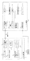
図1はテレビドアホン装置の第1の実施の形態を示すもので、1は玄関などのドアに取付けられたカメラ玄関子機、2は室内に設置されたモニタ室内機で、これらカメラ玄関子機1とモニタ室内機2の間は通話ライン3により接続されている。
【0022】
上記カメラ玄関子機1は、来訪者が通話する際に操作する呼出しボタン4を有する呼出しボタン制御部5を有しており、この呼出しボタン制御部5の呼出しボタン4には、照度測定回路6が接続されている。
【0023】
上記照度測定回路6は、ドア外側の室外の照度を検出する照度センサ7と、上記呼出しボタン4に直列に接続されたインピーダンス8より構成されていて、照度センサ7により検出された室外の照度に応じてインピーダンス8が変化するようになっている。
【0024】
また上記呼出しボタン制御部5は、モニタ室内機I/F回路9を介して通話ライン3に接続されていると共に、モニタ室内機I/F回路9には、来訪者を撮像するカメラ部10が接続されていて、このカメラ部10により撮像された来訪者の映像は、通話ライン3を経由して室内に設置されたモニタ室内機2へ送られるようになっている。
【0025】
一方上記モニタ室内機2は、通話ライン3より送られてきたカメラ玄関子機1からの信号を受信するカメラ玄関子機I/F回路11を有していて、このカメラ玄関子機I/Fかいろ11で受信された信号は、着信インピーダンス判定回路14を介して制御部15へ送られると共に、表示部12が接続されていて、カメラ玄関子機1のカメラ部10で撮像された映像は、表示部12に表示されるようになっている。
【0026】
また上記制御部15には、昼間及び夜間の着信を設定する昼夜間設定スイッチ16と、カメラ玄関子機1から着信信号が入力された場合、着信を知らせるべくスピーカ18を鳴動する着信鳴動回路17及び照明制御回路19が接続されており、照明制御回路19の出力側には、ドアの外側に設置された照明手段20が接続されている。
【0027】
次に上記構成されたテレビドアホン装置の作用を説明すると、モニタ室内機2内の昼夜間設定スイッチ16により昼間も夜間も着信するように予め設定してある場合、来訪者がカメラ玄関子機1の呼出しボタン4を押すと、照度センサ7により検出された照度により変化されたインピーダンス8が通話ライン3に印加されると共に、カメラ部10が撮像した来訪者の映像がモニタ室内機I/F回路9より通話ライン3を経由してモニタ室内機2のカメラ玄関子機I/F回路11へ送られる。
【0028】
モニタ室内機のカメラ玄関子機I/F回路11へ送られた信号は、着信インピーダンス判定回路14を介して制御部15へ送られると共に、着信インピーダンス判定回路14は通話ライン3のインピーダンスの変化により昼間か夜間かを判定し、その結果を制御部15へと送る。
【0029】
制御部15は入力された信号により、まず着信鳴動回路17がスピーカ18を鳴動して、着信を知らせると共に、表示部駆動回路13により表示部12を駆動して、表示部12に来訪者の映像を表示する。
【0030】
また着信インピーダンス判定回路14から夜間の判定信号が入力された場合は、照明制御回路19へ制御信号を送って照明制御回路19により照明手段20を点灯し、ドアの外側を照明する。
【0031】
これによって室内にいる人は、表示部12に表示される来訪者の映像を見ながら、来訪者と通話が行えるようになると共に、カラーモニタ室内機2を使用している場合は、照明手段20により照明された来訪者の鮮明な映像がカラー映像として表示部12へ表示されるようになる。
【0032】
なお予め昼夜間設定スイッチ16により夜間は着信しないを設定した場合は、夜間カメラ玄関子機1の呼出しボタン4を押しても、モニタ室内機2の制御部15は上述したような着信動作を行わないため、スピーカ18が鳴動したり、表示部12へ来訪者の映像が表示されたり、照明手段20が点灯されることがない。
【0033】
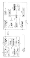
一方図2はテレビドアホン装置の第2の実施の形態を示すもので、次にこれを説明する。
【0034】
なお上記第1の実施の形態と同一部分は同一符号を付してその説明は省略する。
【0035】
この第2の実施の形態では、カメラ玄関子機1に室外の照度を検出する照度測定回路22と、予め設定された照度基準値23が設けられていて、照度測定回路22が検出した室外の照度と、照度基準値を比較回路24が比較するようになっており、比較結果はインピーダンス変換回路25へ送られて、比較結果に応じたインピーダンスに変換された後、通話ライン3へ印加されるようになっている。
【0036】
またモニタ室内機2には、制御部15に屋外モニタボタン26が増設されていて、この屋外モニタボタン26を押すと、制御回路15より照明制御回路19へ制御信号が出力されて、屋外モニタボタン26を押している間、または予め設定された時間照明手段20が点灯されると同時に、表示部12に来訪者の映像が表示されるようになっている。
【0037】
次に上記構成されたテレビドアホン装置の作用を説明すると、モニタ室内機2内の昼夜間設定スイッチ16により昼間も夜間も着信するように予め設定してある場合、来訪者がカメラ玄関子機1の呼出しボタン4を押すと、照度測定回路22により屋外の照度が検出され、比較回路24へ送る。
【0038】
比較回路24は照度測定回路22が検出した照度と、予め設定された照度基準値23を比較して、その偏差をインピーダンス変換回路25へ出力する。
【0039】
インピーダンス変換回路25は、入力された偏差値をインピーダンスに変換してモニタ室内機I/F回路3を介して通話ライン3へ印加すると共に、カメラ部10が撮像した来訪者の映像がモニタ室内機I/F回路9より通話ライン3を経由してモニタ室内機2のカメラ玄関子機I/F回路11へ送られる。
【0040】
モニタ室内機2のカメラ玄関子機I/F回路11へ送られた信号は、着信インピーダンス判定回路14を介して制御部15へ送られると共に、着信インピーダンス判定回路14は通話ライン3のインピーダンスの変化により昼間か夜間かを判定し、その結果を制御部15へと送る。
【0041】
制御部15は入力された信号により、まず着信鳴動回路17がスピーカ18を鳴動して、着信を知らせると共に、表示部駆動回路13により表示部12を駆動して、表示部12に来訪者の映像を表示する。
【0042】
また着信インピーダンス判定回路14から夜間の判定信号が入力された場合は、照明制御回路19へ制御信号を送って照明制御回路19により照明手段20を点灯し、ドアの外側を照明する。
【0043】
これによって室内にいる人は、表示部12に表示される来訪者の映像を見ながら、来訪者と通話が行えるようになると共に、カラーモニタ室内機2を使用している場合は、照明手段20により照明された来訪者の鮮明な映像がカラー映像として表示部12に表示されるようになる。
【0044】
また着信音が鳴動しない場合でも、モニタ室内機2の屋外モニタボタン26の場合は、カメラ玄関子機1が動作されて、カメラ部10が撮像した屋外の映像が通話ライン3を介してモニタ室内機1へ取り込まれて表示部12に屋外の映像が表示され、通話ライン3のインピーダンスの変化により夜間と判定された場合は、制御部15より制御信号が照明制御回路19へと出力されて照明手段20が点灯され、屋外が照明される。
【0045】
これによってカメラ玄関子機1の呼出しボタン4が押されていない状態でも、表示部12に表示される映像により、屋外の様子を監視することができる。
【0046】
なお予め昼夜間設定スイッチ16により夜間は着信しないを設定した場合は、夜間カメラ玄関子機1の呼出しボタン4を押しても、モニタ室内機2の制御部15は上述したような着信動作を行わないため、スピーカ18が鳴動したり、表示部12へ来訪者の映像が表示されたり、照明手段20が点灯されることがない。
【0047】
また異なる室内に複数のモニタ室内機2をそれぞれ設置して、昼夜間設定スイッチ16により、昼間に着信されるモニタ室内機2を設定したり、夜間のみ着信させるモニタ室内機2を設定したり、昼夜間に着信される室内機2を設定することもできる。
【0048】
一方図3はテレビドアホン装置の第3の実施の形態を示すもので、次にこれを説明する。
【0049】
なお上記第1の実施の形態及び第2の実施の形態と同一部分は同一符号を付してその説明は省略する。
【0050】
この実施の形態3では、照度測定回路が検出した屋外の照度と、予め設定された照度基準値23の偏差を、比較回路24より昼夜判定回路28へ送って、その偏差により昼間及び夜間の判定を行っている。
【0051】
そしてその判定結果をキャリヤ発生回路29へ送って、判定結果に応じた一定周波数のキャリヤを発生させ、このキャリヤをモニタ室内機I/F回路9より通話ライン3へ送出している。
【0052】
またモニタ室内機2側には、カメラ玄関子機1より通話ライン3を経由してカメラ玄関子機I/F回路11へ送られてきた信号よりキャリヤを検出するキャリヤ検出回路30が設けられていて、このキャリヤ検出回路30により、キャリヤの周波数から昼夜の判定が行われ、その結果が映像信号と共に制御部15へ送られるようになっている。
【0053】
次の上記構成されたテレビドアホン装置の作用を説明すると、モニタ室内機2内の昼夜間設定スイッチ16により昼間も夜間も着信するように予め設定してある場合、来訪者がカメラ玄関子機1の呼出しボタン4を押すと、照度測定回路22により屋外の照度が検出され、比較回路24へ送る。
【0054】
比較回路24は照度測定回路22が検出した照度と、予め設定された照度基準値23を比較して、その偏差を昼夜間判定回路28へ送る。
【0055】
昼夜間判定回路28は、入力された偏差より昼間か夜間かを判定し、判定結果をキャリヤ発生回路29へ送る。
【0056】
キャリヤ発生回路29は、判定結果に応じて一定周波数のキャリヤを発生させ、このキャリヤがモニタ室内機I/F回路9を介して通話ライン3へ送出されると共に、カメラ部10が撮像した来訪者の映像がモニタ室内機I/F回路11へ送出される。
【0057】
モニタ室内機2のカメラ玄関子機I/F回路11へ送られてきた信号は、キャリヤ検出回路30を介して制御部15へ送られる際、キャリヤ検出回路30により信号中のキャリヤの周波数が検出され、その周波数から昼間か夜間かが判定され、制御部15へ出力される。
【0058】
制御部15は、入力された信号により、まず着信鳴動回路17がスピーカ18を鳴動して、着信を知らせると共に、表示部駆動回路13により表示部12を駆動して、表示部12に来訪者の映像を表示する。
【0059】
またキャリヤ検出回路30から夜間の判定信号が入力された場合は、照明制御回路19へ制御信号を送って照明制御回路19により照明手段20を点灯し、ドアの外側を照明する。
【0060】
これによって室内にいる人は、表示部12に表示される来訪者の映像を見ながら、来訪者と通話が行えるようになると共に、カラーモニタ室内機2を使用している場合は、照明手段20により照明された来訪者の鮮明な映像がカラー映像として表示部12へ表示されるようになる。
【0061】
また着信音が鳴動しない場合でも、モニタ室内機2の屋外モニタボタン26の場合は、カメラ玄関子機1が動作されて、カメラ部10が撮像した屋外の映像が通話ライン3を介してモニタ室内機1へ取り込まれて表示部12に屋外の映像が表示され、通話ライン3のインピーダンスの変化により夜間と判定された場合は、制御部15より制御信号が照明制御回路19へと出力されて照明手段20が点灯され、屋外が照明される。
【0062】
これによってカメラ玄関子機1の呼出しボタン4が押されていない状態でも、表示部12に表示される映像により、屋外の様子を監視することができる。
【0063】
なお予め昼夜間設定スイッチ16により夜間は着信しないを設定した場合は、夜間カメラ玄関子機1の呼出しボタン4を押しても、モニタ室内機2の制御部15は上述したような着信動作を行わないため、スピーカ18が鳴動したり、表示部12へ来訪者の映像が表示されたり、照明手段20が点灯されることがない。
【0064】
また異なる室内に複数のモニタ室内機2をそれぞれ設置して、昼夜間設定スイッチ16により、昼間に着信されるモニタ室内機2を設定したり、夜間のみ着信させるモニタ室内機2を設定したり、昼夜間に着信される室内機2を設定することもできる。
【0065】
この発明は以上詳述したように、来訪者がカメラ玄関子機の呼出しボタンを押すと、カメラ部が撮像した映像がモニタ室内機の表示部へ表示されると同時に、通話ラインのインピーダンスの変化により昼夜を判定し、夜間の場合はドア外側に設置した照明手段を点灯して来訪者を照明するようにしたことから、夜間であっても来訪者の映像を表示部に表示することができる。
【0066】
これによって来訪者が誰であるかを確認しながら通話が行えると共に、カラーテレビドアホン装置を使用している場合は、表示部に鮮明なカラー映像を表示することができる。
【0067】
また昼夜間設定スイッチにより、昼夜間着信できるように設定したり、昼間のみ着信できるように設定したり、また複数の室内に設置したモニタ室内機を昼間と夜間で選択的に着信できるように設定することができるため、従来のテレビインタホン装置に比べて使用できる機能が大幅に増大し、汎用性も高いなどの効果がある。
【図面の簡単な説明】
【図1】この発明の第1の実施の形態になるテレビドアホン装置を示すブロック図
【図2】この発明の第2の実施の形態になるテレビドアホン装置を示すブロック図
【図3】この発明の第3の実施の形態になるテレビドアホン装置を示すブロック図
【符号の説明】
1 カメラ玄関子機
2 モニタ室内機
3 通話ライン
4 呼出しボタン
5 呼出しボタン制御部
6 照度測定回路
7 照度センサ
8 インピーダンス
9 モニタ室内機I/F回路
10 カメラ部
11 カメラ玄関子機I/F回路
12 表示部
13 表示部駆動回路
14 着信インピーダンス判定回路
15 制御部
16 昼夜間設定スイッチ
17 着信鳴動回路
18 スピーカ
19 照明制御回路
20 照明手段
22 照度測定回路
23 照度基準値
24 比較回路
25 インピーダンス変換回路
26 屋外モニタボタン
28 昼夜間判定回路
29 キャリヤ発生回路
30 キャリヤ検出回路[0001]
BACKGROUND OF THE INVENTION
The present invention relates to a television door phone apparatus capable of making a phone call by mixing images between a camera entrance cordless handset installed at a front door or the like and a monitor indoor unit installed indoors.
[0002]
[Prior art]
Conventionally, as this type of TV door phone device, for example, a device described in JP-A-7-15723 is known.
[0003]
The television doorphone device of this publication is a television doorphone device composed of a child device installed at a front door or the like and a parent device installed in a house, a means for changing the amount of accumulated photocharge in the image sensor, An adjustment unit that automatically adjusts the amplification degree, a detection unit that detects the accumulated amount of the photoelectric charge and the amplification degree of the adjustment unit, and a call volume that is controlled according to a detection value detected by the detection unit And a control means, and the call volume between the slave unit and the master unit can be adjusted according to the brightness of the subject.
[Problems to be solved by the invention]
However, although the conventional TV door phone device has the effect of preventing the inconvenience of the neighborhood by reducing the call volume at night, it can restrict calls between the master unit and the slave unit at night. There is a problem that the functions are limited because operations such as setting the master and slave units installed in the room to be able to selectively receive calls during the day and night are not possible.
[0005]
The present invention has been made to remedy such conventional problems, and restricts calls between the camera entrance unit and the monitor indoor unit during the day and night, or is selective to monitor indoor units installed in a plurality of rooms. It is an object of the present invention to provide a multi-function TV door phone device that can be set to receive incoming calls.
[0006]
[Means for Solving the Problems]
In order to achieve the above object, the present invention comprises a camera entrance unit installed outdoors, a monitor indoor unit installed indoors, and a call line connecting the camera entrance unit and the monitor indoor unit. In the television door phone apparatus, the camera entrance cordless handset applies an illuminance measuring means for detecting outdoor illuminance, an impedance for changing a value according to the illuminance detected by the illuminance measuring means, and applying the impedance to the call line. Calling means for making a call, and the monitor indoor unit detects a change in impedance of the call line when called by the calling means to determine day and night, and a day / night determination means A day / night incoming call control means for controlling day / night incoming calls based on the determination result is provided.
[0007]
DETAILED DESCRIPTION OF THE INVENTION
According to a first aspect of the present invention, there is provided a camera entrance unit installed outdoors, a monitor indoor unit installed indoors, and a call line connecting the camera entrance unit and the monitor indoor unit. In the television door phone apparatus, the camera entrance cordless handset has an illuminance measuring means for detecting outdoor illuminance, an impedance for changing a value according to the illuminance detected by the illuminance measuring means, and applying the impedance to the call line. Calling means for making a call, and the monitor indoor unit detects a change in impedance of the call line when called by the calling means to determine day and night, and the day / night determination means And day / night incoming call control means for controlling day / night incoming calls based on the determination result .
[0008]
With the above configuration, when a visitor presses the call button on the camera entrance cordless handset, the image captured by the camera unit is displayed on the display unit of the monitor indoor unit installed indoors. Yes.
[0009]
In addition, since the impedance whose value is changed according to the outdoor illuminance detected by the illuminance measuring means provided in the camera entrance unit is applied to the call line, the day / night determination means provided in the monitor indoor unit is connected to the impedance of the call line. It is possible to determine daytime and nighttime by detecting the change of daytime and nighttime, and by the daytime / nighttime incoming call control means, it is possible to perform control such as prohibiting a call between the camera entrance unit and the monitor indoor unit at nighttime.
[0012]
According to a second aspect of the present invention, the illuminance measurement means of the camera door unit detects an illuminance outdoors, a detection value detected by the illuminance measurement circuit, and a preset illuminance reference value a comparator circuit for outputting a deviation by comparing, in which a impedance conversion circuit for converting the deviation outputted from the comparator circuit to the impedance.
[0013]
With the above-described configuration, the outdoor illuminance detected by the illuminance measuring circuit and the preset illuminance reference value are compared by the comparison circuit to perform day / night determination, so that the day / night determination can be performed with high accuracy.
[0016]
According to a third aspect of the present invention, the monitor indoor unit is provided with illumination control means for turning on the illumination installed outdoors when the day / night determination means determines that it is nighttime.
[0017]
With the above configuration, visitors can be easily confirmed even at night, and in the case of a color television door phone device, a clear color image can be displayed on the display unit of the monitor indoor unit.
[0018]
According to a fourth aspect of the present invention, the monitor indoor unit includes day / night setting means that can selectively receive calls during the day and at night based on the determination by the day / night determination means .
[0019]
With the above configuration, settings such as setting an incoming call to a monitor indoor unit in another room during the day and night, or prohibiting a call between the night camera entrance unit and the monitor indoor unit can be easily performed.
[0020]
Hereinafter, embodiments of the present invention will be described in detail with reference to the drawings.
[0021]
FIG. 1 shows a first embodiment of a TV door phone apparatus, wherein 1 is a camera entrance unit attached to a door such as an entrance, and 2 is a monitor indoor unit installed indoors. 1 and the monitor
[0022]
The camera entrance
[0023]
The illuminance measurement circuit 6 includes an illuminance sensor 7 for detecting the illuminance outside the door outside and an
[0024]
The call button control unit 5 is connected to the
[0025]
On the other hand, the monitor
[0026]
Also to the
[0027]
Next, the operation of the TV door phone apparatus configured as described above will be described. When the daytime /
[0028]
The signal sent to the camera entrance slave I / F circuit 11 of the monitor indoor unit is sent to the
[0029]
In response to the input signal, the
[0030]
When a nighttime determination signal is input from the incoming
[0031]
As a result, a person in the room can make a call with the visitor while watching the video of the visitor displayed on the display unit 12, and when using the color monitor
[0032]
If the day /
[0033]
On the other hand, FIG. 2 shows a second embodiment of the television door phone apparatus, which will be described next.
[0034]
The same parts as those in the first embodiment are denoted by the same reference numerals, and the description thereof is omitted.
[0035]
In the second embodiment, the camera entrance
[0036]
In the monitor
[0037]
Next, the operation of the TV door phone apparatus configured as described above will be described. When the daytime /
[0038]
The comparison circuit 24 compares the illuminance detected by the
[0039]
The
[0040]
The signal sent to the camera entrance slave I / F circuit 11 of the monitor
[0041]
In response to the input signal, the
[0042]
When a nighttime determination signal is input from the incoming
[0043]
As a result, a person in the room can make a call with the visitor while watching the video of the visitor displayed on the display unit 12, and when using the color monitor
[0044]
Even when the ring tone does not sound, in the case of the
[0045]
As a result, even when the call button 4 of the camera entrance
[0046]
If the day /
[0047]
In addition, a plurality of monitor
[0048]
On the other hand, FIG. 3 shows a third embodiment of the television door phone apparatus, which will be described next.
[0049]
The same parts as those in the first embodiment and the second embodiment are denoted by the same reference numerals, and the description thereof is omitted.
[0050]
In the third embodiment, the difference between the outdoor illuminance detected by the illuminance measurement circuit and the preset
[0051]
The determination result is sent to the carrier generation circuit 29 to generate a carrier having a constant frequency according to the determination result, and this carrier is sent from the monitor indoor unit I / F circuit 9 to the
[0052]
On the monitor
[0053]
Next, the operation of the TV door phone apparatus configured as described above will be described. When the daytime /
[0054]
The comparison circuit 24 compares the illuminance detected by the
[0055]
The day /
[0056]
The carrier generation circuit 29 generates a carrier having a constant frequency according to the determination result, and the carrier is sent to the
[0057]
When the signal sent to the camera entrance slave unit I / F circuit 11 of the monitor
[0058]
In response to the input signal, the
[0059]
When a nighttime determination signal is input from the carrier detection circuit 30, a control signal is sent to the
[0060]
As a result, a person in the room can make a call with the visitor while watching the video of the visitor displayed on the display unit 12, and when using the color monitor
[0061]
Even when the ring tone does not sound, in the case of the
[0062]
As a result, even when the call button 4 of the camera entrance
[0063]
If the day /
[0064]
In addition, a plurality of monitor
[0065]
As described in detail above, when the visitor presses the call button of the camera entrance cordless handset, the image captured by the camera unit is displayed on the display unit of the monitor indoor unit, and at the same time, the impedance of the call line changes. Because the lighting means installed on the outside of the door is turned on to illuminate the visitor at night, the video of the visitor can be displayed on the display unit even at night. .
[0066]
This makes it possible to make a call while confirming who the visitor is, and when a color television door phone device is used, a clear color image can be displayed on the display unit.
[0067]
The day / night setting switch allows you to receive calls during the day and night, allows you to receive only during the day, and allows you to selectively receive monitor indoor units installed in multiple rooms during the day and night. Therefore, the functions that can be used are greatly increased and the versatility is high as compared with the conventional TV intercom apparatus.
[Brief description of the drawings]
FIG. 1 is a block diagram showing a television door phone device according to a first embodiment of the present invention. FIG. 2 is a block diagram showing a television door phone device according to a second embodiment of the invention. The block diagram which shows the television door phone apparatus which becomes 3rd Embodiment of this invention
DESCRIPTION OF
Claims (4)
Priority Applications (1)
| Application Number | Priority Date | Filing Date | Title |
|---|---|---|---|
| JP03225798A JP3773346B2 (en) | 1998-01-30 | 1998-01-30 | TV door phone device |
Applications Claiming Priority (1)
| Application Number | Priority Date | Filing Date | Title |
|---|---|---|---|
| JP03225798A JP3773346B2 (en) | 1998-01-30 | 1998-01-30 | TV door phone device |
Publications (2)
| Publication Number | Publication Date |
|---|---|
| JPH11220722A JPH11220722A (en) | 1999-08-10 |
| JP3773346B2 true JP3773346B2 (en) | 2006-05-10 |
Family
ID=12353971
Family Applications (1)
| Application Number | Title | Priority Date | Filing Date |
|---|---|---|---|
| JP03225798A Expired - Fee Related JP3773346B2 (en) | 1998-01-30 | 1998-01-30 | TV door phone device |
Country Status (1)
| Country | Link |
|---|---|
| JP (1) | JP3773346B2 (en) |
Families Citing this family (1)
| Publication number | Priority date | Publication date | Assignee | Title |
|---|---|---|---|---|
| CN104580896B (en) * | 2014-12-25 | 2018-06-22 | 深圳市锐明技术股份有限公司 | A kind of video camera diurnal pattern switching method and apparatus |
-
1998
- 1998-01-30 JP JP03225798A patent/JP3773346B2/en not_active Expired - Fee Related
Also Published As
| Publication number | Publication date |
|---|---|
| JPH11220722A (en) | 1999-08-10 |
Similar Documents
| Publication | Publication Date | Title |
|---|---|---|
| JP3773346B2 (en) | TV door phone device | |
| JP2009171245A (en) | Interphone system | |
| JP4966143B2 (en) | Intercom system | |
| KR100279807B1 (en) | Home Auto Media System with Removable Monitor | |
| JP3084176B2 (en) | TV door phone equipment | |
| JP3596654B2 (en) | Color television door phone | |
| KR100279809B1 (en) | Home Auto Media System with Removable Monitor | |
| JP3198371B2 (en) | TV door phone equipment | |
| JP4362177B2 (en) | TV door phone device | |
| JP2615487B2 (en) | TV door phone equipment | |
| KR970003468B1 (en) | Video door-phone using television | |
| JP3846660B2 (en) | Camera control device | |
| JP2000224573A (en) | Television intercom device | |
| JP2005286539A (en) | Video doorphone apparatus | |
| JPH04269089A (en) | Color television device | |
| JPH05122704A (en) | Gatedoor camera equipment | |
| JP2006081064A (en) | Television interphone unit | |
| JP2660283B2 (en) | Intercom system with monitor TV | |
| JPH0432389A (en) | Doorphone system with television receiver | |
| JPH04269090A (en) | Color television receiver | |
| JP2602468Y2 (en) | TV door phone equipment | |
| JPH1013822A (en) | Interphone system | |
| JPH06141324A (en) | Multi-function television interphone set | |
| JPH06315151A (en) | Video interphone device | |
| JPH0720774U (en) | Monitor TV unit for intercom |
Legal Events
| Date | Code | Title | Description |
|---|---|---|---|
| A521 | Written amendment |
Free format text: JAPANESE INTERMEDIATE CODE: A523 Effective date: 20040625 |
|
| A621 | Written request for application examination |
Free format text: JAPANESE INTERMEDIATE CODE: A621 Effective date: 20040625 |
|
| A131 | Notification of reasons for refusal |
Free format text: JAPANESE INTERMEDIATE CODE: A131 Effective date: 20060104 |
|
| A521 | Written amendment |
Free format text: JAPANESE INTERMEDIATE CODE: A523 Effective date: 20060123 |
|
| TRDD | Decision of grant or rejection written | ||
| A01 | Written decision to grant a patent or to grant a registration (utility model) |
Free format text: JAPANESE INTERMEDIATE CODE: A01 Effective date: 20060214 |
|
| A61 | First payment of annual fees (during grant procedure) |
Free format text: JAPANESE INTERMEDIATE CODE: A61 Effective date: 20060214 |
|
| R150 | Certificate of patent or registration of utility model |
Free format text: JAPANESE INTERMEDIATE CODE: R150 |
|
| FPAY | Renewal fee payment (event date is renewal date of database) |
Free format text: PAYMENT UNTIL: 20100224 Year of fee payment: 4 |
|
| FPAY | Renewal fee payment (event date is renewal date of database) |
Free format text: PAYMENT UNTIL: 20100224 Year of fee payment: 4 |
|
| FPAY | Renewal fee payment (event date is renewal date of database) |
Free format text: PAYMENT UNTIL: 20110224 Year of fee payment: 5 |
|
| FPAY | Renewal fee payment (event date is renewal date of database) |
Free format text: PAYMENT UNTIL: 20120224 Year of fee payment: 6 |
|
| FPAY | Renewal fee payment (event date is renewal date of database) |
Free format text: PAYMENT UNTIL: 20130224 Year of fee payment: 7 |
|
| LAPS | Cancellation because of no payment of annual fees |