JP3772956B2 - Image forming apparatus and sheet supply unit used therefor - Google Patents
Image forming apparatus and sheet supply unit used therefor Download PDFInfo
- Publication number
- JP3772956B2 JP3772956B2 JP34120199A JP34120199A JP3772956B2 JP 3772956 B2 JP3772956 B2 JP 3772956B2 JP 34120199 A JP34120199 A JP 34120199A JP 34120199 A JP34120199 A JP 34120199A JP 3772956 B2 JP3772956 B2 JP 3772956B2
- Authority
- JP
- Japan
- Prior art keywords
- image forming
- sheet supply
- sheet
- unit
- conveyance path
- Prior art date
- Legal status (The legal status is an assumption and is not a legal conclusion. Google has not performed a legal analysis and makes no representation as to the accuracy of the status listed.)
- Expired - Fee Related
Links
Images


Classifications
-
- B—PERFORMING OPERATIONS; TRANSPORTING
- B65—CONVEYING; PACKING; STORING; HANDLING THIN OR FILAMENTARY MATERIAL
- B65H—HANDLING THIN OR FILAMENTARY MATERIAL, e.g. SHEETS, WEBS, CABLES
- B65H3/00—Separating articles from piles
-
- B—PERFORMING OPERATIONS; TRANSPORTING
- B65—CONVEYING; PACKING; STORING; HANDLING THIN OR FILAMENTARY MATERIAL
- B65H—HANDLING THIN OR FILAMENTARY MATERIAL, e.g. SHEETS, WEBS, CABLES
- B65H3/00—Separating articles from piles
- B65H3/44—Simultaneously, alternately, or selectively separating articles from two or more piles
-
- G—PHYSICS
- G03—PHOTOGRAPHY; CINEMATOGRAPHY; ANALOGOUS TECHNIQUES USING WAVES OTHER THAN OPTICAL WAVES; ELECTROGRAPHY; HOLOGRAPHY
- G03G—ELECTROGRAPHY; ELECTROPHOTOGRAPHY; MAGNETOGRAPHY
- G03G15/00—Apparatus for electrographic processes using a charge pattern
- G03G15/65—Apparatus which relate to the handling of copy material
- G03G15/6502—Supplying of sheet copy material; Cassettes therefor
- G03G15/6511—Feeding devices for picking up or separation of copy sheets
-
- G—PHYSICS
- G03—PHOTOGRAPHY; CINEMATOGRAPHY; ANALOGOUS TECHNIQUES USING WAVES OTHER THAN OPTICAL WAVES; ELECTROGRAPHY; HOLOGRAPHY
- G03G—ELECTROGRAPHY; ELECTROPHOTOGRAPHY; MAGNETOGRAPHY
- G03G15/00—Apparatus for electrographic processes using a charge pattern
- G03G15/65—Apparatus which relate to the handling of copy material
- G03G15/6555—Handling of sheet copy material taking place in a specific part of the copy material feeding path
- G03G15/6558—Feeding path after the copy sheet preparation and up to the transfer point, e.g. registering; Deskewing; Correct timing of sheet feeding to the transfer point
-
- G—PHYSICS
- G03—PHOTOGRAPHY; CINEMATOGRAPHY; ANALOGOUS TECHNIQUES USING WAVES OTHER THAN OPTICAL WAVES; ELECTROGRAPHY; HOLOGRAPHY
- G03G—ELECTROGRAPHY; ELECTROPHOTOGRAPHY; MAGNETOGRAPHY
- G03G2215/00—Apparatus for electrophotographic processes
- G03G2215/00362—Apparatus for electrophotographic processes relating to the copy medium handling
- G03G2215/00535—Stable handling of copy medium
- G03G2215/00544—Openable part of feed path
-
- G—PHYSICS
- G03—PHOTOGRAPHY; CINEMATOGRAPHY; ANALOGOUS TECHNIQUES USING WAVES OTHER THAN OPTICAL WAVES; ELECTROGRAPHY; HOLOGRAPHY
- G03G—ELECTROGRAPHY; ELECTROPHOTOGRAPHY; MAGNETOGRAPHY
- G03G2215/00—Apparatus for electrophotographic processes
- G03G2215/00362—Apparatus for electrophotographic processes relating to the copy medium handling
- G03G2215/00535—Stable handling of copy medium
- G03G2215/00548—Jam, error detection, e.g. double feeding
-
- G—PHYSICS
- G03—PHOTOGRAPHY; CINEMATOGRAPHY; ANALOGOUS TECHNIQUES USING WAVES OTHER THAN OPTICAL WAVES; ELECTROGRAPHY; HOLOGRAPHY
- G03G—ELECTROGRAPHY; ELECTROPHOTOGRAPHY; MAGNETOGRAPHY
- G03G2221/00—Processes not provided for by group G03G2215/00, e.g. cleaning or residual charge elimination
- G03G2221/16—Mechanical means for facilitating the maintenance of the apparatus, e.g. modular arrangements and complete machine concepts
- G03G2221/1696—Mechanical means for facilitating the maintenance of the apparatus, e.g. modular arrangements and complete machine concepts for auxiliary devices, e.g. add-on modules
Description
【0001】
【発明の属する技術分野】
本発明は、複写機やプリンタなどの画像形成装置に係り、特に、画像形成ユニットにシート供給ユニットを並列配置したタイプの画像形成装置及びこれに用いられるシート供給ユニットの改良に関する。
【0002】
【従来の技術】
最近の画像形成装置においては、カラー化、高速化、高寿命化などの要請から、画像形成ユニット内に収容される作像モジュールのうち、例えば現像部や転写部のサイズが大型化してきており、これらが画像形成装置の高さ方向寸法を占有する割合が増加しつつある。
このような状況下において、作像モジュールの記録シートへの転写位置が下方寄りに移動せしめられることになり、シート搬送路も装置の下方部に設定せざるを得ない状態になっている。
一方、シート供給部は、通常作像モジュールの下方スペースを利用して設けられているが、前述したように、作像モジュール自体が大型化してくると、作像モジュールの下方にシート供給部として多段のシート供給トレイを設置することが不可能になってくる。
すなわち、作像モジュールの大型化に関係なく、従前通り、多段のシート供給トレイを設置すると、作像モジュールの相対的位置が高くなり、その分、画像形成ユニット自体の高さ寸法を高く設定せざるを得ず、画像形成ユニットの操作部位置がユーザーにとって操作し難い位置になってしまうという弊害が生ずる。
逆に、画像形成ユニットの操作部位置をユーザーに適した位置に設定しようとすると、必然的に作像モジュールの下方スペースが狭くなってしまい、その分、シート供給部として大容量のシート供給トレイを設置することが実質的に困難になってしまう。
【0003】
このような技術的課題を解決するために、画像形成ユニットの側方に多段のシート供給トレイが収容されたシート供給ユニットを並列配置するようにした技術が既に提案されている(例えば特開平3−182431号公報参照)。
【0004】
【発明が解決しようとする課題】
しかしながら、この種の先行技術にあっては、各シート供給トレイからの記録シートの送出方向はいずれも画像形成ユニット側からの同一方向であり、シート供給ユニット内において各シート供給トレイの画像形成ユニット側には各シート供給トレイからのシート搬送路が集中配置された後に、シート供給ユニットのシート送出口から画像形成ユニット側へ送出されるようになっている。
この場合において、そもそも、装置サイズをなるべく小さくするという観点から、シート供給トレイとシート供給ユニットの画像形成ユニット側壁面との間のスペースが狭いため、各シート供給ユニットからのシート搬送路が集中配置されると、シート搬送路でのジャム処理のための機構が複雑になってしまうばかりか、ジャム処理に伴う操作が面倒になり易いという技術的課題が生じてしまう。
【0005】
このような技術的課題を解決する手法としては、ジャム処理時などにおいてシート供給ユニットを画像形成ユニットから離間する方向へ移動させ、ジャム処理などのための作業スペースを確保するということが考えられるが、重量の大きなシート供給ユニットをジャム処理などの度に移動させるということはジャム処理作業性の点で好ましいものとは言えない。
【0006】
本発明は、以上の技術的課題を解決するためになされたものであって、シート供給ユニットが付設された態様のものを前提とし、シート供給ユニット内でのジャム処理を容易に実現することが可能な画像形成装置及びこれに用いられるシート供給ユニットを提供する。
【0007】
【課題を解決するための手段】
すなわち、本発明は、図1に示すように、供給された記録シート5に対して画像を作成する作像モジュール2が収容される画像形成ユニット1と、この画像形成ユニット1に並列配置され、一若しくは複数段のシート供給トレイ4(例えば4a〜4c)を有し且つシート供給トレイ4に収容された記録シート5を画像形成ユニット1側へ送出するシート供給ユニット3とを備え、シート供給ユニット3としては、少なくとも一部のシート供給トレイ4(本例では4a,4b)からのシート搬送路を画像形成ユニット1の反対側から延びる迂回搬送路6として構成し、画像形成ユニット1の反対側に位置するユニットケース7には前記迂回搬送路6に面して開閉せしめられる開閉カバー8を具備させたことを特徴とする。
【0008】
このような技術的手段において、作像モジュール2としては、図1に示すように、中間転写型のタンデムモジュールに限られるものではなく、各種のモジュールを含むものである。
特に、記録シート5に対して両面転写や多重転写を行う作像モジュール2にあっては、片面画像形成済みの記録シート5を直接若しくは反転して再度転写部へ戻すシート戻し搬送機構2aなどが付設される。
【0009】
また、迂回搬送路6については、少なくとも一部のシート供給トレイ4(例えば4a,4b)に設ければよいが、勿論、全てのシート供給トレイ4に設ける態様をも含む。
ここで、迂回搬送路6については、図1では、シート供給トレイ4の側方から上方スペースを利用して画像形成ユニット1側へ導かれているが、これに限られるものではなく、例えば側方から下方スペースを利用して画像形成ユニット1側へ導くようにしてもよい。
【0010】
更に、開閉カバー8については、迂回搬送路6に面して開閉するものであればよいが、開閉カバー8解放時における迂回搬送路6でのジャム処理性を良好に保つという観点からすれば、開閉カバー8は、迂回搬送路6部分に設けられる対構成の搬送部材(図示せず)の一方側を具備し、開閉カバー8開放時には搬送部材のニップ状態を解除するものであるものが好ましい。
【0011】
また、一部のシート供給トレイ4(4a,4b)に対して迂回搬送路6を設ける態様にあっては、シート供給ユニット3は、少なくとも一部のシート供給トレイ4(本例では4c)からのシート搬送路を画像形成ユニット1側から延びる直結搬送路9として構成することになる。
この態様にあっては、迂回搬送路6と直結搬送路9との二系統のシート搬送路を具備することになるが、例えば塗工紙、厚紙などの曲げ剛性の高い特殊シートについて直結搬送路9につながるシート供給トレイ4(例えば4c)を使用するようにすれば、記録シート5の搬送に伴う変形やジャムを有効に防止することができる点で好ましい。
【0012】
また、本発明は、画像形成装置にのみならず、これに用いられるシート供給ユニット3そのものをも対象とする。
この場合、本発明は、図1に示すように、供給された記録シート5に対して画像を作成する作像モジュール2が収容される画像形成ユニット1を備えた画像形成装置に用いられ、前記画像形成ユニット1に並列配置され且つ一若しくは複数段のシート供給トレイ4(例えば4a〜4c)に収容された記録シート5を画像形成ユニット1側へ送出するシート供給ユニット3であって、少なくとも一部のシート供給トレイ4(4a,4b)からのシート搬送路を画像形成ユニット1の反対側から延びる迂回搬送路6として構成し、画像形成ユニット1の反対側に位置するユニットケース7には前記迂回搬送路6が開閉せしめられる開閉カバー8を具備させたことを特徴とする。
【0013】
また、カラー化、高機能化などの各種要請に伴って作像モジュール2をより高度に設計するに際しては、図1に示すように、一若しくは複数段のシート供給トレイ4を有し且つシート供給トレイ4に収容された記録シート5を外部へ送出するシート供給ユニット3と、このシート供給ユニット3に並列配置され、少なくとも前記シート供給ユニット3を含む外部シート供給源から供給された記録シート5に対してのみ画像を作成する作像モジュール2が収容される画像形成ユニット1とを備えた態様が好ましい。
この態様において、シート供給ユニット3は一つであるものに限られず、複数列並設したものをも含む。また、画像形成ユニット1は、内部にシート供給源を有さず、少なくともシート供給ユニット3を含む外部シート供給源(例えば画像形成ユニットの手差しトレイなどを含む)から供給された記録シート5に対してのみ画像形成を行うものであればよい。
このように、画像形成ユニットに並列配置されるシート供給ユニット側に全てのシート供給トレイを収容するようにすれば、カラー化、高速化、多機能化などの各種要請に従って画像形成ユニット内の作像モジュールをより高度なものに設計することが容易になり、画像形成装置の高性能化をより簡単に実現することができる。
【0014】
【発明の実施の形態】
以下、添付図面に示す実施の形態に基づいて本発明を詳細に説明する。
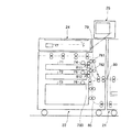
図2は本発明が適用された画像形成装置の実施の一形態を示す説明図である。
同図において、本実施の形態に係る画像形成装置は所謂タンデム型の中間転写方式を採用した画像形成装置であり、作像モジュール30が収容された画像形成ユニット21と、この画像形成ユニット21に並列配置されて記録シート(図示せず)を画像形成ユニット21に供給するシート供給ユニット22と、前記画像形成ユニット21に並列配置されて画像形成ユニット21にて画像形成された記録シートに対して後処理を施す後処理ユニット23とを備えたものである。
【0015】
本実施の形態において、画像形成ユニット21は、例えば電子写真方式にて各色成分トナー像(例えばイエロ(Y),マゼンタ(M),シアン(C),ブラック(K))が形成される作像モジュール30を収容したものであり、この作像モジュール30は、各色成分トナー像を形成担持する感光体ドラム31(具体的には31Y,31M,31C,31K)を並列配置し、各感光体ドラム31で形成した各色成分トナー像を中間転写ベルト40に順次一次転写させ、二次転写ロール50にてシート供給ユニット22から供給される記録シートに中間転写ベルト40上の各色成分トナー像を二次転写させ、定着器60に導くようにしたものである。
【0016】
本実施の形態において、各感光体ドラム31の周囲には、感光体ドラム31を帯電する一様帯電器(図示せず)、感光体ドラム31上に静電潜像を書込むレーザ露光器33、各色成分トナーが収容されて感光体ドラム31上の静電潜像を可視像化する現像器34、感光体ドラム31上の各色成分トナー像を中間転写ベルト40に転写せしめる一次転写ロール35及び感光体ドラム31上の残留トナーなどを除去するクリーナ36などの電子写真用デバイスが順次配設されている。
また、中間転写ベルト40は複数(本例では5つ)の張架ロール41〜45に張架されて循環搬送されるものであり、例えば張架ロール41を駆動ロールとすると共に、他の張架ロール42〜45を従動ロールとし、更に張架ロール42〜45のうちの任意の張架ロール、例えば張架ロール43を中間転写ベルト40に張力が付与せしめられるテンションロールとして機能させるようにしたものである。
そして、本実施の形態では、中間転写ベルト40の張架ロール44に対向する部位が二次転写部位として設定されており、この中間転写ベルト40の二次転写部位表面側には二次転写ロール50が接触配置され、この二次転写ロール50とこれに対向する張架ロール44(バックアップロールとして機能)との間に転写バイアスが印加されるようになっている。
【0017】
更に、本実施の形態において、シート供給ユニット22は、特に図3に示すように、多段(本例では3段)のシート供給トレイ71〜73を有し、シート供給トレイ71,72にはサイズの異なる普通紙からなる記録シートを収容する一方、最下段の大容量シート供給トレイ73には、塗工紙、厚紙等の曲げ剛性の高い記録シートを含む特殊シートを収容ようにしたものである。
特に、本実施の形態では、シート供給トレイ71,72は、画像形成ユニット21の反対側にフィードロール74,75を有し、シート供給トレイ73は画像形成ユニット21側にフィードロール76を有している。
そして、シート供給トレイ71,72からのシート搬送路は、シート供給ユニット22の画像形成ユニット21の反対側側方から上方へ向かい、上方スペースを利用して画像形成ユニット21側へと向かった後、下方へと向かう迂回搬送路77として構成されている。
一方、シート供給トレイ73からのシート搬送路は、画像形成ユニット21側へ略直線状に延びる直結搬送路78として構成されており、この直結搬送路78及び前記迂回搬送路77は合流搬送路79に連通接続され、記録シートを送出口80から画像形成ユニット21側へ送出するようになっている。
【0018】
更に、シート供給ユニット22の迂回搬送路77、直結搬送路78及び合流搬送路79には対構成の複数の搬送ロール81が所定間隔毎に設けられている。
特に、シート供給ユニット22のユニットケース220のうち、画像形成ユニット21の反対側に位置する部分には、迂回搬送路77に面して開閉するカバー100が設けられている。
このカバー100は、図4に示すように、例えばユニットケース220の奥側を回転支点として回動するものであり、対構成の搬送ロール81(81a,81b)のうち従動ロール81bを回動自在に保持するものであり、開放時において搬送ロール81の駆動ロール81aと従動ロール81bとを分離配置するものである。
また、本実施の形態では、シート供給ユニット22の迂回搬送路77の水平搬送路部分には、画像形成ユニット21の反対側に向かって水平方向に延びる連結搬送路101が形成されており、この連結搬送路101は、例えばシート供給ユニット22に隣接して別のシート供給ユニット(図示せず)を配設した態様において、別のシート供給ユニットから供給される記録シートを受け入れ、迂回搬送路77へと案内する搬送路として働いたり、あるいは、シート供給ユニット22の手差しによる記録シートの挿入部として働くようになっている。
【0019】
更にまた、本実施の形態では、シート供給ユニット22の上方に、画像読取りユニット24及びユーザー操作部25が配設されている。
尚、画像読取りユニット24は、原稿台に置かれた原稿の画像を光学的に読み取るものであり、例えば光源、反射ミラー、結像レンズ、CCDセンサ等から構成される。
【0020】
また、本実施の形態において、後処理ユニット23は、画像形成ユニット21のユニットケース210に形成された記録シートの排出口211に対応したユニットケース230位置に入口開口231を有し、一方、画像形成ユニット21の反対側のユニットケース230位置に出口開口232を開設している。
本例では、入口開口231は後処理ユニット23の下半部の所定位置(例えば高さ300〜450mm程度)に設けられ、一方、出口開口232は後処理ユニット23の上半部の所定位置(例えば750mm〜850mm程度)に設けられ、出口開口232に対応したユニットケース230にはシート排出トレイ233が取り付けられている。
更に、入口開口231と出口開口232との間には斜め方向に向かう傾斜搬送路234が設けられており、この傾斜搬送路234は途中で二つに分岐し、各分岐搬送路にはアップカール矯正用、ダウンカール矯正用のカール矯正装置235,236が配設されている。
【0021】
また、画像形成ユニット21内のシート搬送路は、シート供給ユニット22から供給された記録シートを二次転写部位に導いた後に、定着器60を通過させて後処理ユニット23側へ排出する経路以外に、定着器60から送出された記録シートを反転して再度二次転写部位に戻す経路を備えている。
ここで、本実施の形態では、二次転写部位の上流側に配置された複数(例えば3つ)の対構成からなる搬送斜行ロール82にてサイド初期位置に記録シートの側端を合わせた後、二次転写部位の手前に配置された対構成のレジストレーションロール(レジストロール)83にて記録シートを基準位置に揃え且つ位置合わせした状態で二次転写部位へ搬送し、二次転写部位通過後の記録シートを例えば搬送ベルト84にて定着器60へと搬送するようにしたものである。
【0022】
更に、本実施の形態で用いられるシート戻し機構としては、定着器60から送出された記録シートをループ状の戻し経路85に沿って適宜数の搬送ロール86にて搬送するものであるが、戻し経路85の途中に反転部(本例では後処理ユニット23内の下部スペースを利用して構成)87を設け、この反転部87を介して記録シートを反転させるようにしたものである。
尚、戻し経路85の一部はシート供給ユニット22内のスペースを利用し、合流搬送路79に連通接続されるようになっている。
【0023】
次に、本実施の形態に係る画像形成装置の作動について説明する。
今、シート供給ユニット22のシート供給トレイ71又は72のいずれかから記録シートが送出されたとすると、この記録シートは迂回搬送路77及び合流搬送路79を経て送出口80から画像形成ユニット21側へ送出され、搬送斜行ロール82及びレジストロール83を経て二次転写部位へ搬送される。
この状態において、作像モジュール30にて形成されたカラートナー像が記録シートに転写され、転写済みの記録シートは定着器60を経た後、後処理ユニット23側へ搬送される。
そして、後処理ユニット23側では、記録シートは傾斜搬送路234を経て搬送されるが、この過程において、記録シートにカールが発生している条件下にて例えばカール矯正装置235,236のいずれかの後処理(カール矯正)が行われ、シート排出トレイ233へ排出される。
【0024】
また、シート供給トレイ73から送出される記録シートは塗工紙、厚紙等を含む特殊シートであるが、直結搬送路78及び合流搬送路79を経て送出口80から画像形成ユニット21側へ送出されるため、特に曲げ変形、ジャムなどせずに、二次転写部位に搬送されるようになっている。
【0025】
このような動作過程において、例えばシート供給トレイ71又は72から記録シートが送出された直後にジャムしたと仮定すると、ジャム処理としては、カバー100を開放した状態で、迂回搬送路77のうち、シート供給トレイ71又は72から送出された直後に停滞している記録シートを除去するようにすればよい。
また、シート供給ユニット22の画像形成ユニット21側のシート搬送路部分で記録シートがジャムしたような場合であっても、例えば図5に示すようなジャム処理機構を設けるようにすれば、簡単にジャム処理を行うことが可能である。
【0026】
図5において、ジャム処理機構は、迂回搬送路77の右下方部を内側固定ガイドシュート151、つまみ153操作にて矢印方向へ移動自在な外側可動ガイドシュート152及び外側固定ガイドシュート154で区画し、また、合流搬送路79を下側固定ガイドシュート155及びつまみ157操作にて矢印方向へ移動自在な上側可動ガイドシュート156で区画し、また、直結搬送路78を前記内側固定ガイドシュート151の一部及びつまみ159操作にて矢印方向へ移動自在な下側可動ガイドシュート158で区画し、更に、戻し経路85の一部を前記下側可動ガイドシュート158と一体的に動く外側可動ガイドシュート160、外側固定ガイドシュート161、つまみ163操作にて矢印方向へ移動自在な上側可動ガイドシュート162及び内側固定ガイドシュート164で区画するようにしたものである。尚、符号165は手前側に開閉する開閉扉である。
【0027】
このジャム処理機構にあっては、シート搬送路中のジャムが発生した箇所に対応する可動ガイドシュートを移動させる操作を行うことで、シート搬送路中に停滞している記録シートを容易に除去することができる。
ここで、本実施の形態に係るジャム処理機構によるジャム処理作業が容易であることを図6に示す比較の形態を例に挙げて説明する。
図6に示す比較の形態は、シート供給トレイ71〜73からの記録シートの送り出し方向を画像形成ユニット21側に設定し、全て直結搬送路781〜783(783は図5の78に相当)を介して合流搬送路79へと記録シートを導くようにしたものである。
この態様においては、図5に示すジャム処理機構に加えて、シート供給トレイ71,72からの直結搬送路781,782が追加になり、この直結搬送路781,782を区画するシュート部分に開放機構及び搬送ロール811,812を付加しなければならず、シュート構成が複雑化してしまうばかりか、シュート部分でのジャム処理スペースが極めて狭いため、シート供給トレイ71又は72から送出された直後の記録シートにジャム処理は極めて困難である。
【0028】
また、本実施の形態にあっては、シート供給トレイ73からのシート搬送路は直結搬送路78を用いているが、例えばシート供給トレイ73についても普通紙を使用するような態様にあっては、図7に示すように、シート供給トレイ71〜73に対し画像形成ユニット21の反対側から延びる迂回搬送路77を設けるようにしてもよい。
この場合において、シート供給トレイ71〜73から送出された直後の記録シートがジャムした際のジャム処理性を良好に保つには、図7に示すように、迂回搬送路77の画像形成ユニット21の反対側側方に面した部位全域に亘って開閉カバー100を設けるようにすることが好ましい。
【0029】
【発明の効果】
以上説明してきたように、本発明によれば、シート供給ユニットが付設された画像形成装置を前提とし、少なくとも一部のシート供給トレイからのシート搬送路を画像形成ユニットの反対側から延びる迂回搬送路とし、画像形成ユニットの反対側に位置するユニットケースに迂回搬送路に対するジャム処理用の開閉カバーを設けるようにしたので、少なくとも迂回搬送路につながるシート供給トレイの記録シート送出部でのジャム処理については開閉カバーを開放することで簡単に行うことができるほか、シート供給ユニットの画像形成ユニット側付近のシート搬送路の密集状態を緩和することができる分、この部分でのジャム処理についても比較的簡単に実現することができ、シート供給ユニット内でのジャム処理を容易に実現することができる。
【図面の簡単な説明】
【図1】 本発明に係る画像形成装置及びこれに用いられるシート供給ユニットの概要を示す説明図である。
【図2】 実施の形態に係る画像形成装置の全体構成を示す説明図である。
【図3】 実施の形態で用いられるシート供給ユニットの詳細を示す説明図である。
【図4】 実施の形態で用いられる迂回搬送路の開閉カバー周りの構造を示す説明図である。
【図5】 実施の形態で用いられるシート供給ユニットの画像形成ユニット側周辺のジャム処理機構の一例を示す説明図である。
【図6】 比較の形態に係るシート供給ユニットの一例を示す説明図である。
【図7】 実施の形態で用いられるシート供給ユニットの変形形態を示す説明図である。
【符号の説明】
1…画像形成ユニット,2…作像モジュール,2a…シート戻し搬送機構,3…シート供給ユニット,4(4a〜4c)…シート供給トレイ,5…記録シート,6…迂回搬送路,7…ユニットケース,8…開閉カバー,9…直結搬送路[0001]
BACKGROUND OF THE INVENTION
The present invention relates to an image forming apparatus such as a copying machine or a printer, and more particularly to an image forming apparatus of a type in which a sheet supply unit is arranged in parallel with an image forming unit and an improvement of a sheet supply unit used therefor.
[0002]
[Prior art]
In recent image forming apparatuses, due to demands for colorization, high speed, and long life, among the image forming modules accommodated in the image forming unit, for example, the size of the developing unit and the transfer unit has been increased. The ratio of these to occupy the height dimension of the image forming apparatus is increasing.
Under such circumstances, the transfer position of the image forming module to the recording sheet is moved downward, and the sheet conveyance path must be set at the lower portion of the apparatus.
On the other hand, the sheet supply unit is usually provided using the lower space of the image forming module. As described above, when the image forming module itself is enlarged, the sheet supply unit is provided below the image forming module as a sheet supply unit. It becomes impossible to install a multi-stage sheet supply tray.
In other words, regardless of the size of the image forming module, if a multi-stage sheet supply tray is installed as before, the relative position of the image forming module increases, and accordingly, the height dimension of the image forming unit itself must be set higher. Inevitably, the operation unit position of the image forming unit becomes a position that is difficult for the user to operate.
On the contrary, if the operation unit position of the image forming unit is set to a position suitable for the user, the space below the image forming module is inevitably narrowed, and accordingly, a large capacity sheet supply tray as the sheet supply unit. It becomes practically difficult to install.
[0003]
In order to solve such a technical problem, a technique has already been proposed in which sheet supply units each containing a multi-stage sheet supply tray are arranged in parallel on the side of the image forming unit (for example, Japanese Patent Laid-Open No. Hei 3). -182431).
[0004]
[Problems to be solved by the invention]
However, in this type of prior art, the recording sheet delivery direction from each sheet supply tray is the same direction from the image forming unit side, and the image forming unit of each sheet supply tray in the sheet supply unit. On the side, after the sheet conveyance paths from the respective sheet supply trays are arranged in a concentrated manner, they are sent out from the sheet delivery port of the sheet supply unit to the image forming unit side.
In this case, from the standpoint of reducing the apparatus size as much as possible, the space between the sheet supply tray and the side wall surface of the image forming unit of the sheet supply unit is narrow, so the sheet conveyance paths from each sheet supply unit are centrally arranged. Then, the mechanism for jam processing in the sheet conveyance path becomes complicated, and a technical problem arises that the operation accompanying the jam processing tends to be troublesome.
[0005]
As a technique for solving such a technical problem, it is conceivable to move the sheet supply unit in a direction away from the image forming unit at the time of jam processing or the like to secure a working space for jam processing or the like. It is not preferable from the viewpoint of jam handling workability to move a heavy sheet supply unit every time jam handling is performed.
[0006]
The present invention has been made in order to solve the above technical problem, and is premised on a mode in which a sheet supply unit is attached, and can easily realize jam processing in the sheet supply unit. A possible image forming apparatus and a sheet supply unit used therefor are provided.
[0007]
[Means for Solving the Problems]
That is, according to the present invention, as shown in FIG. 1, an
[0008]
In such technical means, the image forming module 2 is not limited to the intermediate transfer type tandem module as shown in FIG. 1, but includes various modules.
In particular, in the image forming module 2 that performs double-sided transfer or multiple transfer on the recording sheet 5, a sheet
[0009]
Further, the detour conveyance path 6 may be provided in at least a part of the sheet supply trays 4 (for example, 4a and 4b), but of course includes an aspect provided in all the sheet supply trays 4.
Here, the detour conveyance path 6 is guided to the
[0010]
Furthermore, the opening /
[0011]
Further, in the aspect in which the detour conveyance path 6 is provided for some of the sheet supply trays 4 (4a, 4b), the sheet supply unit 3 starts from at least some of the sheet supply trays 4 (4c in this example). This sheet conveyance path is configured as a direct conveyance path 9 extending from the
In this aspect, there are provided two sheet conveyance paths, that is, the detour conveyance path 6 and the direct connection conveyance path 9. For example, a direct connection conveyance path for a special sheet having high bending rigidity such as coated paper and cardboard. Use of a sheet supply tray 4 (for example, 4c) connected to 9 is preferable in that deformation and jam accompanying the conveyance of the recording sheet 5 can be effectively prevented.
[0012]
Further, the present invention is intended not only for the image forming apparatus but also for the sheet supply unit 3 itself used in the image forming apparatus.
In this case, as shown in FIG. 1, the present invention is used in an image forming apparatus including an
[0013]
Further, in order to design the image forming module 2 with a higher level in response to various requests such as colorization and higher functionality, as shown in FIG. 1, the sheet supply tray 4 has one or a plurality of stages and a sheet supply tray. A sheet supply unit 3 for sending the recording sheet 5 accommodated in the tray 4 to the outside, and a recording sheet 5 arranged in parallel to the sheet supply unit 3 and supplied from an external sheet supply source including at least the sheet supply unit 3 The aspect provided with the
In this embodiment, the sheet supply unit 3 is not limited to a single sheet supply unit, and includes a plurality of sheet supply units arranged in parallel. Further, the
In this way, if all the sheet supply trays are accommodated on the side of the sheet supply unit arranged in parallel with the image forming unit, the operation in the image forming unit can be performed according to various requests such as colorization, high speed, and multi-functionality. It becomes easy to design an image module with a higher level, and the performance of the image forming apparatus can be easily realized.
[0014]
DETAILED DESCRIPTION OF THE INVENTION
Hereinafter, the present invention will be described in detail based on embodiments shown in the accompanying drawings.
FIG. 2 is an explanatory diagram showing an embodiment of an image forming apparatus to which the present invention is applied.
In the figure, the image forming apparatus according to the present embodiment is an image forming apparatus that employs a so-called tandem intermediate transfer system, and includes an
[0015]
In the present embodiment, the
[0016]
In the present embodiment, a uniform charger (not shown) for charging the photosensitive drum 31 is provided around each photosensitive drum 31, and a
Further, the
In this embodiment, a portion of the
[0017]
Further, in the present embodiment, the
In particular, in the present embodiment, the
Then, after the sheet conveyance path from the
On the other hand, the sheet conveyance path from the
[0018]
Further, a plurality of paired conveyance rolls 81 are provided at predetermined intervals on the
In particular, a portion of the
As shown in FIG. 4, the
In the present embodiment, a connecting
[0019]
Furthermore, in the present embodiment, an
The
[0020]
Further, in the present embodiment, the
In this example, the
Further, an
[0021]
Further, the sheet conveyance path in the
Here, in the present embodiment, the side edge of the recording sheet is aligned with the side initial position by the conveying
[0022]
Further, as the sheet return mechanism used in the present embodiment, the recording sheet sent from the fixing
A part of the
[0023]
Next, the operation of the image forming apparatus according to the present embodiment will be described.
Assuming that a recording sheet is sent from either the
In this state, the color toner image formed by the
Then, on the
[0024]
The recording sheet sent from the
[0025]
In such an operation process, for example, assuming that a jam occurs immediately after a recording sheet is sent out from the
Further, even when the recording sheet is jammed in the sheet conveyance path portion on the
[0026]
In FIG. 5, the jam handling mechanism divides the lower right portion of the
[0027]
In this jam processing mechanism, the recording sheet stagnating in the sheet conveyance path is easily removed by performing an operation of moving the movable guide chute corresponding to the position where the jam occurs in the sheet conveyance path. be able to.
Here, the fact that the jam handling operation by the jam handling mechanism according to the present embodiment is easy will be described by taking a comparative example shown in FIG. 6 as an example.
In the comparative form shown in FIG. 6, the recording sheet delivery direction from the
In this embodiment, in addition to the jam handling mechanism shown in FIG. 5,
[0028]
In the present embodiment, the
In this case, as shown in FIG. 7, the
[0029]
【The invention's effect】
As described above, according to the present invention, on the premise of the image forming apparatus provided with the sheet supply unit, the detour conveyance extending from the opposite side of the image formation unit through the sheet conveyance path from at least some of the sheet supply trays. The unit case located on the opposite side of the image forming unit is provided with an opening / closing cover for jam handling to the detour conveyance path, so that at least the jam processing in the recording sheet sending section of the sheet supply tray connected to the detour conveyance path In addition to opening and closing the cover, it can be done easily, and the jamming in this part is also compared because the density of the sheet conveyance path near the image forming unit side of the sheet supply unit can be eased. Can be realized easily, and jam processing in the sheet supply unit can be easily realized. Kill.
[Brief description of the drawings]
FIG. 1 is an explanatory diagram showing an outline of an image forming apparatus according to the present invention and a sheet supply unit used therefor.
FIG. 2 is an explanatory diagram illustrating an overall configuration of an image forming apparatus according to an embodiment.
FIG. 3 is an explanatory diagram showing details of a sheet supply unit used in the embodiment.
FIG. 4 is an explanatory diagram showing a structure around an opening / closing cover of a detour conveyance path used in the embodiment.
FIG. 5 is an explanatory diagram illustrating an example of a jam processing mechanism around the image forming unit side of the sheet supply unit used in the embodiment.
FIG. 6 is an explanatory diagram illustrating an example of a sheet supply unit according to a comparative embodiment.
FIG. 7 is an explanatory view showing a modified form of the sheet supply unit used in the embodiment.
[Explanation of symbols]
DESCRIPTION OF
Claims (4)
シート供給ユニットは、少なくとも一部のシート供給トレイからのシート搬送路を画像形成ユニットの反対側から延びる迂回搬送路として構成し、画像形成ユニットの反対側に位置するユニットケースには前記迂回搬送路に面して開閉せしめられる開閉カバーを具備させたことを特徴とする画像形成装置。An image forming unit that stores an image forming module that creates an image with respect to the supplied recording sheet, and one or a plurality of stages of sheet supply trays that are arranged in parallel to the image forming unit, and are stored in the sheet supply tray A sheet supply unit that sends the recorded sheet to the image forming unit side,
The sheet supply unit configures a sheet conveyance path from at least a part of the sheet supply tray as a detour conveyance path extending from the opposite side of the image forming unit, and the unit case located on the opposite side of the image forming unit includes the detour conveyance path. An image forming apparatus comprising an opening / closing cover that can be opened and closed facing the surface.
開閉カバーは、迂回搬送路部分に設けられる対構成の搬送部材の一方側を具備し、開閉カバー開放時には搬送部材のニップ状態を解除するものであることを特徴とする画像形成装置。The image forming apparatus according to claim 1.
The image forming apparatus, wherein the opening / closing cover includes one side of a pair of conveying members provided in a detour conveying path portion, and releases the nip state of the conveying member when the opening / closing cover is opened.
シート供給ユニットは、少なくとも一部のシート供給トレイからのシート搬送路を画像形成ユニット側から延びる直結搬送路として構成したことを特徴とする画像形成装置。The image forming apparatus according to claim 1.
An image forming apparatus, wherein the sheet supply unit is configured such that a sheet conveyance path from at least some of the sheet supply trays is a direct connection conveyance path extending from the image forming unit side.
少なくとも一部のシート供給トレイからのシート搬送路を画像形成ユニットの反対側から延びる迂回搬送路として構成し、画像形成ユニットの反対側に位置するユニットケースには前記迂回搬送路が開閉せしめられる開閉カバーを具備させたことを特徴とするシート供給ユニット。Used in an image forming apparatus having an image forming unit for storing an image forming module for creating an image with respect to a supplied recording sheet, arranged in parallel with the image forming unit and arranged in one or a plurality of sheet supply trays. A sheet supply unit for sending the stored recording sheet to the image forming unit side;
The sheet conveyance path from at least a part of the sheet supply tray is configured as a bypass conveyance path extending from the opposite side of the image forming unit, and the opening and closing that allows the bypass conveyance path to be opened and closed in a unit case located on the opposite side of the image forming unit A sheet supply unit comprising a cover.
Priority Applications (4)
| Application Number | Priority Date | Filing Date | Title |
|---|---|---|---|
| JP34120199A JP3772956B2 (en) | 1999-11-30 | 1999-11-30 | Image forming apparatus and sheet supply unit used therefor |
| KR10-2000-0068058A KR100427464B1 (en) | 1999-11-30 | 2000-11-16 | Image forming device and sheet providing unit therefor |
| US09/721,770 US6975413B1 (en) | 1999-11-30 | 2000-11-27 | Image forming apparatus and sheet supply unit for use in the same |
| TW089125201A TW483863B (en) | 1999-11-30 | 2000-11-28 | Image forming device and sheet feeding unit using the same |
Applications Claiming Priority (1)
| Application Number | Priority Date | Filing Date | Title |
|---|---|---|---|
| JP34120199A JP3772956B2 (en) | 1999-11-30 | 1999-11-30 | Image forming apparatus and sheet supply unit used therefor |
Publications (3)
| Publication Number | Publication Date |
|---|---|
| JP2001151365A JP2001151365A (en) | 2001-06-05 |
| JP2001151365A5 JP2001151365A5 (en) | 2005-04-07 |
| JP3772956B2 true JP3772956B2 (en) | 2006-05-10 |
Family
ID=18344162
Family Applications (1)
| Application Number | Title | Priority Date | Filing Date |
|---|---|---|---|
| JP34120199A Expired - Fee Related JP3772956B2 (en) | 1999-11-30 | 1999-11-30 | Image forming apparatus and sheet supply unit used therefor |
Country Status (4)
| Country | Link |
|---|---|
| US (1) | US6975413B1 (en) |
| JP (1) | JP3772956B2 (en) |
| KR (1) | KR100427464B1 (en) |
| TW (1) | TW483863B (en) |
Families Citing this family (2)
| Publication number | Priority date | Publication date | Assignee | Title |
|---|---|---|---|---|
| US7934718B2 (en) * | 2005-03-24 | 2011-05-03 | Xerox Corporation | Sheet feeding of faster rate printing systems with plural slower rate sheet feeders |
| KR20180057182A (en) | 2016-11-22 | 2018-05-30 | 에이치피프린팅코리아 주식회사 | Image forming apparatus |
Family Cites Families (3)
| Publication number | Priority date | Publication date | Assignee | Title |
|---|---|---|---|---|
| JPH03182431A (en) | 1989-12-11 | 1991-08-08 | Canon Inc | Connecting system for sheet feeder |
| US5289236A (en) * | 1992-03-24 | 1994-02-22 | Kabushiki Kaisha Toshiba | Image forming apparatus |
| JPH07181758A (en) * | 1993-12-22 | 1995-07-21 | Konica Corp | Both-side copying device |
-
1999
- 1999-11-30 JP JP34120199A patent/JP3772956B2/en not_active Expired - Fee Related
-
2000
- 2000-11-16 KR KR10-2000-0068058A patent/KR100427464B1/en active IP Right Grant
- 2000-11-27 US US09/721,770 patent/US6975413B1/en not_active Expired - Lifetime
- 2000-11-28 TW TW089125201A patent/TW483863B/en not_active IP Right Cessation
Also Published As
| Publication number | Publication date |
|---|---|
| US6975413B1 (en) | 2005-12-13 |
| JP2001151365A (en) | 2001-06-05 |
| KR20010051737A (en) | 2001-06-25 |
| KR100427464B1 (en) | 2004-04-30 |
| TW483863B (en) | 2002-04-21 |
Similar Documents
| Publication | Publication Date | Title |
|---|---|---|
| JP5177683B2 (en) | Image reading apparatus and copying machine | |
| US7570906B2 (en) | Tandem type color image forming machine | |
| JP2012201424A (en) | Image forming device | |
| JP2001302114A (en) | Image forming device | |
| US6085063A (en) | Digital image forming apparatus | |
| US20130266357A1 (en) | Recording medium ejection device and image forming apparatus | |
| JP4189281B2 (en) | Image forming apparatus | |
| JP2809654B2 (en) | Image forming device | |
| JPH061471A (en) | Image formation device | |
| JP3398064B2 (en) | Image forming device | |
| JP3772956B2 (en) | Image forming apparatus and sheet supply unit used therefor | |
| JPS6283976A (en) | Picture forming device | |
| JP3582313B2 (en) | Image forming device | |
| JP4467456B2 (en) | Paper transport mechanism of image forming apparatus | |
| JP2005041629A (en) | Image forming device | |
| JP4666381B2 (en) | Image forming apparatus | |
| JP4588588B2 (en) | Document transport device, document transport reading unit and copier using the same | |
| JP3881820B2 (en) | Image forming apparatus | |
| JP2001220046A (en) | Image forming device and after-processing unit used in the same | |
| JP2004069932A (en) | Image forming apparatus | |
| JPH0641951Y2 (en) | Paper feeding device of image forming apparatus | |
| JP2007022719A (en) | Image forming device | |
| JP2024003577A (en) | Image forming apparatus | |
| JP2001222139A (en) | Double-sided device | |
| JP2894572B2 (en) | Paper transport device |
Legal Events
| Date | Code | Title | Description |
|---|---|---|---|
| A521 | Written amendment |
Free format text: JAPANESE INTERMEDIATE CODE: A523 Effective date: 20040426 |
|
| A621 | Written request for application examination |
Free format text: JAPANESE INTERMEDIATE CODE: A621 Effective date: 20040426 |
|
| A977 | Report on retrieval |
Free format text: JAPANESE INTERMEDIATE CODE: A971007 Effective date: 20051012 |
|
| A131 | Notification of reasons for refusal |
Free format text: JAPANESE INTERMEDIATE CODE: A131 Effective date: 20051102 |
|
| A521 | Written amendment |
Free format text: JAPANESE INTERMEDIATE CODE: A523 Effective date: 20051226 |
|
| TRDD | Decision of grant or rejection written | ||
| A01 | Written decision to grant a patent or to grant a registration (utility model) |
Free format text: JAPANESE INTERMEDIATE CODE: A01 Effective date: 20060125 |
|
| A61 | First payment of annual fees (during grant procedure) |
Free format text: JAPANESE INTERMEDIATE CODE: A61 Effective date: 20060207 |
|
| R150 | Certificate of patent or registration of utility model |
Free format text: JAPANESE INTERMEDIATE CODE: R150 |
|
| FPAY | Renewal fee payment (event date is renewal date of database) |
Free format text: PAYMENT UNTIL: 20100224 Year of fee payment: 4 |
|
| FPAY | Renewal fee payment (event date is renewal date of database) |
Free format text: PAYMENT UNTIL: 20110224 Year of fee payment: 5 |
|
| FPAY | Renewal fee payment (event date is renewal date of database) |
Free format text: PAYMENT UNTIL: 20120224 Year of fee payment: 6 |
|
| FPAY | Renewal fee payment (event date is renewal date of database) |
Free format text: PAYMENT UNTIL: 20130224 Year of fee payment: 7 |
|
| FPAY | Renewal fee payment (event date is renewal date of database) |
Free format text: PAYMENT UNTIL: 20130224 Year of fee payment: 7 |
|
| FPAY | Renewal fee payment (event date is renewal date of database) |
Free format text: PAYMENT UNTIL: 20140224 Year of fee payment: 8 |
|
| LAPS | Cancellation because of no payment of annual fees |