JP3772695B2 - Non-contact automatic ticket gate - Google Patents
Non-contact automatic ticket gate Download PDFInfo
- Publication number
- JP3772695B2 JP3772695B2 JP2001176763A JP2001176763A JP3772695B2 JP 3772695 B2 JP3772695 B2 JP 3772695B2 JP 2001176763 A JP2001176763 A JP 2001176763A JP 2001176763 A JP2001176763 A JP 2001176763A JP 3772695 B2 JP3772695 B2 JP 3772695B2
- Authority
- JP
- Japan
- Prior art keywords
- contact
- recording medium
- token
- automatic ticket
- ticket gate
- Prior art date
- Legal status (The legal status is an assumption and is not a legal conclusion. Google has not performed a legal analysis and makes no representation as to the accuracy of the status listed.)
- Expired - Fee Related
Links
Images

Landscapes
- Devices For Checking Fares Or Tickets At Control Points (AREA)
- Credit Cards Or The Like (AREA)
Description
【0001】
【発明の属する技術分野】
本発明は、駅などに設置される非接触式の自動改札装置に関するものである。
【0002】
【従来の技術】
非接触式自動改札装置は、非接触記録媒体に記録された情報を非接触で読み取って通行の許可または禁止の処理を行う自動改札装置である。従来、このような非接触式自動改札装置においては、一般に記録媒体として非接触カードが用いられている。しかしながら、非接触カードは通信回路やメモリなどを内蔵しており、コストが高いために、1回使用限りで廃棄処分される普通乗車券として利用するには不向きであり、専ら定期券やプリペイドカードのような反復使用が可能な乗車媒体として利用されている。
【0003】
このため、普通乗車券については従来どおりの磁気券とし、非接触カードと磁気券の双方に対応するために、磁気券専用の自動改札装置と非接触カード専用の自動改札装置とを併設したり、あるいは、磁気券と非接触カードの両方を処理できるハイブリッド式の自動改札装置を採用しているのが現状である。しかるに、前者の場合は2種類の自動改札装置が必要となって不経済であるとともに設置スペースも増大する。また、後者の場合も自動改札装置の内部に磁気券と非接触カードの両方を処理するための機構や回路が必要となるために、やはりコストが高くなるという問題がある。
【0004】
これに対して、特開2000―331198号公報や特開平9―326053号公報には、非接触カードからなる普通乗車券を出場時に回収することで、非接触カードのリサイクルを可能にした非接触式自動改札装置が記載されている。これによると、上記のような2種類の自動改札装置やハイブリッド式の自動改札装置が不要となり、また、普通乗車券を非接触カードで構成しても、これを回収して再利用できるために、運用コストがかからないという利点がある。
【0005】
【発明が解決しようとする課題】
しかしながら、上記各公報に記載された自動改札装置では、普通乗車券と定期券等とがいずれも非接触カードから構成されているために、利用者が出場時に操作を間違いやすいという問題がある。すなわち、1回使用限りの普通乗車券は、出場時に回収する必要があるため、自動改札装置に設けられたカード挿入口へ挿入する必要があるのに対し、定期券等は回収せずに反復使用するものであるため、カード挿入口へ挿入するのではなく、自動改札装置に設けられたアンテナ部にかざす必要がある。ところが、上記のように、普通乗車券も定期券等もカード形状をしておれば、普通券である非接触カードをカード挿入口へ挿入せずにアンテナ部にかざしてしまったり、逆に、定期券である非接触カードをアンテナ部にかざさずにカード挿入口へ挿入してしまうといった間違いが発生する。普通乗車券の非接触カードがアンテナ部にかざされた場合は、カードの回収ができなくなるので通行が禁止され、利用者はあらためて非接触カードをカード挿入口に挿入する必要がある。また、定期券がカード挿入口へ挿入された場合は、利用者に定期券を返却するために、カードを取出口へ放出するようにしているが、このために非接触カードを搬送するための搬送機構が必要となり、装置内部の機構が複雑になる。
【0006】
一方、特開2000―123212号公報には、アンテナ部にかざした非接触カードが回収すべき乗車券である場合は、返却口の扉を開いて、この返却口へカードが投入された後に通行を許可し、また、アンテナ部にかざした非接触カードが回収しない乗車券である場合は、返却口の扉を開かずに、そのまま通行を許可するようにした自動改札装置が記載されている。この公報のものでは、非接触カードを搬送するための搬送機構を必要としない反面、普通乗車券のような回収すべき非接触カードの場合には、出場時において、カードをアンテナ部にかざす操作と、その次にカードを返却口へ投入する操作との2段階の操作が必要となり、利用者にとって操作が煩雑になるという難点がある。
【0007】
本発明は、以上のような問題点を解決するものであって、その課題とするところは、利用者が間違った媒体処理操作を行なうのを防止できるとともに、操作自体も簡便に行なえる非接触式自動改札装置を提供することにある。
【0008】
【課題を解決するための手段】
本発明の非接触式自動改札装置は、非回収媒体である第1の非接触記録媒体の情報を読み取る第1の読取手段と、回収媒体である第2の非接触記録媒体が投入される当該媒体専用の投入口と、投入口に投入された第2の非接触記録媒体が自重で通過するシュートと、シュート内に進入した第2の非接触記録媒体の情報を読み取る第2の読取手段と、シュートの途中に設けられ、第2の読取手段の読み取り結果に基づいて、第2の非接触記録媒体を回収側と返却側とに振り分ける振分部材と、振分部材によって回収側に振り分けられた第2の非接触記録媒体を回収する回収箱と、振分部材によって返却側に振り分けられた第2の非接触記録媒体を返却する返却口とを備える。第2の読取手段は、シュート内に進入した第2の非接触記録媒体が振分部材で受け止められて一旦停止した状態で、当該第2の非接触記録媒体の情報を読み取る。そして、第2の読取手段での読み取り結果が通行許可の場合は、振分部材を回収側に回動させて、当該振分部材で受け止められている第2の非接触記録媒体を回収箱に回収する。また、第2の読取手段での読み取り結果が通行禁止の場合は、振分部材を返却側に回動させて、当該振分部材で受け止められている第2の非接触記録媒体を返却口へ返却する。
【0009】
投入口は第2の非接触記録媒体専用の投入口であることから、利用者は第1の非接触記録媒体を間違って投入口へ投入することはなく、第2の非接触記録媒体を投入口へ投入するようになる。これによって、回収媒体である第2の非接触記録媒体を確実に回収することができるとともに、間違って投入された第1の非接触記録媒体を返却するための搬送機構も不要になる。また、第2の非接触記録媒体はアンテナ部にかざす必要がなく、直接投入口へ投入すればよいので、前記の特開2000―123212号公報のような2段階操作の煩雑さを解消できる。
【0010】
本発明では、第2の読取手段に、第1の非接触記録媒体との間で誤交信が生じるのを防止するためのシールド部材を付設してもよい。
【0011】
本発明の典型的な実施形態においては、第1の非接触記録媒体が非接触カードから構成され、第2の非接触記録媒体が非接触トークンから構成される。また、第1の読取手段が、かざされた非接触カードと通信を行なうカード用アンテナを有し、第2の読取手段が、投入口に投入された非接触トークンと通信を行なうトークン用アンテナを有している。これによると、第1の非接触記録媒体はカードであるのに対し、第2の非接触記録媒体はコイン状のトークンであるので、利用者は両記録媒体を容易に識別することができ、第1の非接触記録媒体を投入口へ入れようとしたり、第2の非接触記録媒体をカード用アンテナにかざそうとする誤操作の防止に一層有効である。
【0012】
本発明では、非接触トークンの投入口が、通行方向(出場方向または入場方向)に向かってカード用アンテナよりも手前に設けられていることが好ましい。これにより、非接触トークンを所持した利用者に対して、投入口へのトークン投入を有効に誘導することができる。また、非接触トークンの投入口の大きさは、非接触カードの投入ができない寸法に設定されていることが好ましい。これにより、非接触カードを間違ってトークンの投入口へ投入する誤操作を皆無にすることができる。
【0013】
また、本発明では、投入口に投入された非接触トークンが自重で通過するシュートと、このシュートの途中に設けられ、トークン用アンテナで読み取られた情報に基づいて非接触トークンを回収側と返却側とに振り分ける振分手段と、この振分手段によって回収側に振り分けられた非接触トークンを回収する回収箱と、振分手段によって返却側に振り分けられた非接触トークンを返却する返却口とを設けることにより、非接触トークンの自重を利用してトークンの回収または返却を行うことができる。これにより、非接触トークンの回収や返却のための搬送機構を設ける必要がなくなり、装置内部の構造が簡略化される。
【0014】
さらに、本発明では、利用者が間違ってカード用アンテナに非接触トークンをかざした場合に、非接触トークンを投入口へ投入するよう案内を行なうことにより、利用者に対して間違いを気付かせ、すみやかな措置をとらせることができる。この案内は、表示部に文字で表示することにより行なってもよいし、音声出力部から音声で知らせることにより行なってもよい。
【0015】
本発明では、前述した非接触式自動改札装置と、第1の非接触記録媒体の情報の読み取りと第2の非接触記録媒体の情報の読み取りとを共用する第3の読取手段を有するが第2の非接触記録媒体の投入口や回収手段を有しない非接触式自動改札装置とを組み合せ、両自動改札装置を通路をはさんで並置してもよい。この場合、利用者が出場するときは、第1の非接触式自動改札装置において、かざされた第1の非接触記録媒体の情報を第1の読取手段が読み取るか、または、投入口に投入された第2の非接触記録媒体の情報を第2の読取手段が読み取る。また、第2の読取手段の読み取り結果に基づいて、第2の非接触記録媒体を回収する。一方、利用者が入場するときは、第2の非接触式自動改札装置において、かざされた第1または第2の非接触記録媒体の情報を第3の読取手段が読み取る。このときは、第2の非接触記録媒体は回収されない。
【0016】
【発明の実施の形態】
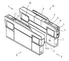
図1は、本発明に係る自動改札装置の一例を示した外観図である。ここでは、2台の自動改札装置A,Bが通路9をはさんで並置されているが、Aが本発明の実施形態に係る自動改札装置である。X,Yは通行方向を表しており、Xは出場方向、Yは入場方向である。本例では、利用者が乗車駅で非接触トークンまたは非接触カードを自動改札装置にかざして入場し、降車駅では非接触トークンを自動改札装置に投入し、非接触カードはかざして出場する運用の場合を例に挙げる。この場合、自動改札装置Aは、X方向へ出場する利用者の非接触トークンが投入され、また非接触カードがかざされる自動改札装置である。一方、自動改札装置Bは、Y方向から入場する利用者の非接触トークンまたは非接触カードがかざされる自動改札装置である。
【0017】
自動改札装置Aは、本体1と、この本体1の上部に設けられたバー2と、本体1の通路9側に設けられた1対の扉3a,3bとを備えている。扉3a,3bは、常時開かれた状態となっている。本体1の上面には、X方向へ出場する利用者に対して各種の案内を行なう表示部4と、後述する非接触カード(図2)との間で通信を行なうカード用アンテナ5とが並んで設けられている。6は後述する非接触トークン(図3)が投入される投入口、7は非接触トークンを返却するための返却口であって、投入口6は出場方向Xに向かってカード用アンテナ5よりも手前に設けられている。また、8は投入口6に投入された非接触トークンと通信を行なうトークン用アンテナである。
【0018】
自動改札装置Bは、自動改札装置Aと同様の形状をした改札装置であり、Y方向から入場する利用者に対して各種の案内を行なう表示部10と、非接触記録媒体および非接触トークンとの間で通信を行なうアンテナ11とが設けられているが、入場時に非接触トークンの回収は行わないので、自動改札装置Aにおけるトークンの投入口6や返却口7、およびトークン用アンテナ8は設けられていない。
【0019】
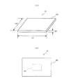
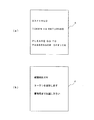
図2は、本発明における第1の非接触記録媒体の一形態をなす非接触カードを示した図であり、(a)は斜視図、(b)は平面図をそれぞれ表している。非接触カードCは、プラスチック等からなるカード本体20と、このカード本体20の内部にモールドされた回路装置21とからなる。回路装置21は、後述するように、アンテナや通信制御回路、メモリ等を備えている。この非接触カードCは、定期券やプリペイドカードのように反復使用する乗車媒体として、駅の窓口または定期券発行機で発行され、たとえば定期券の場合は、媒体コード、乗車区間、経由駅、使用開始日、使用期限などの情報が回路装置21のメモリに記録されている。なお、第1の非接触記録媒体としては、非接触カードCに限らず、腕に装着して使用するブレスレット形状もしくは腕時計形状の非接触記録媒体、あるいは非接触カード機能付き携帯電話機などを用いることもできる。
【0020】
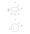
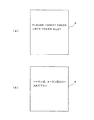
図3は、本発明における第2の非接触記録媒体の一形態をなす非接触トークンを示した図であり、(a)は斜視図、(b)は平面図をそれぞれ表している。非接触トークンTも、非接触カードCと同様に、プラスチック等からなるトークン本体22と、このトークン本体22の内部にモールドされた回路装置23とからなる。回路装置23は、後述するように、アンテナや通信制御回路、メモリ等を備えている。この非接触トークンTは、普通乗車券のような1回使用限りの乗車媒体として、自動券売機で発行され、媒体コード、乗車駅、金額、乗車日などの情報が回路装置23のメモリに記録されている。なお、図3では非接触トークンTは円形となっているが、これに代えて、たとえば8角形や6角形などの非接触トークンを用いてもよい。
【0021】
非接触トークンTは、図3(a)に示したように、コインのような形状をしており、その外径L3の寸法は、図2(a)に示した非接触カードCの長辺L1および短辺L2のいずれの寸法よりも短くなっている。また、非接触トークンTの厚みD2は、非接触カードCの厚みD1よりも厚くなっている。そして、図1における投入口6の大きさは、非接触トークンTの上記各寸法よりもやや大きく設定されており、非接触トークンTは投入できるが、非接触カードCは投入ができない寸法に設定されている。これによって、投入口6は非接触トークン専用の投入口となっている。なお、上記のように投入口6の寸法を規制する代わりに、投入口6に「トークン専用投入口」のような表示をすることで、投入口6を非接触トークン専用の投入口としてもよい。また、寸法規制と表示の両方を採用してもよい。
【0022】
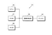
図4は、非接触カードCに内蔵されている回路装置21のブロック図である。図において、30はCPU、31はCPU30の動作プログラム等を記録したROM、32は乗車データ等が記録されるRAM、33は自動改札装置との間で行なわれる送信や受信の動作を制御する通信制御回路、34は自動改札装置側のアンテナと交信を行なうためのアンテナである。なお、CPU30は省略することも可能である。
【0023】
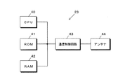
図5は、非接触トークンTに内蔵されている回路装置23のブロック図である。回路装置23は上述した非接触カードCの回路装置21と同様の構成を有しており、40はCPU、41はCPU40の動作プログラム等を記録したROM、42は乗車データ等が記録されるRAM、43は自動改札装置との間で行なわれる送信や受信の動作を制御する通信制御回路、44は自動改札装置側のアンテナと交信を行なうためのアンテナである。なお、CPU40は省略することも可能である。
【0024】
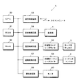
図6は、自動改札装置Aの電気的構成を示したブロック図である。50はCPU、51はCPU50の動作プログラム等を記録したROM、52は乗車データ等が記録されるRAM、53は駅の係員室に設置された上位コンピュータと回線で接続された通信制御回路である。54は表示部4の表示動作を制御する表示制御回路、55は非接触カードとの間で行なわれる送信や受信を制御するための通信制御回路、56はカード用アンテナ5を介して非接触カードの情報を読み取ったり、非接触カードに情報を書き込んだりする非接触カードリーダライタである。カード用アンテナ5と非接触カードリーダライタ56とは、本発明における第1の読取手段の一形態を構成している。
【0025】
57は非接触トークンとの間で行なわれる送信や受信を制御するための通信制御回路、58はトークン用アンテナ8を介して非接触トークンの情報を読み取ったり、非接触トークンに情報を書き込んだりする非接触トークンリーダライタである。トークン用アンテナ8と非接触トークンリーダライタ58とは、本発明における第2の読取手段の一形態を構成している。59は扉制御回路であって、扉3a,3bを開閉するためのモータ60の動作を制御する。なお、自動改札装置Aには、このほか、人間の通過を検知するためのセンサ、非接触トークンの投入を検知するためのセンサ、後述する振分部材を駆動するための駆動回路などが設けられるが、図6では図示を省略している。
【0026】
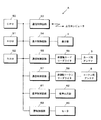
図7は、自動改札装置Aの他の実施形態を示したブロック図であって、図6と同一部分には同一符号を付してある。図7では、図6の構成に加えて音声制御回路61と、音声出力部62とが設けられている。音声出力部62は、後述する音声案内を行なうためのもので、スピーカなどから構成され、自動改札装置Aの適当な箇所に配置される。音声制御回路61は音声出力部62の動作を制御するものである
【0027】
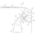
図8は、自動改札装置Aの投入口6付近の内部機構を示した断面図である。13は投入口6と連続して設けられたシュートであって、投入口6から投入された非接触トークンTは、このシュート13を自重で通過するようになっている。14は投入口6の近傍に設けられたセンサであって、非接触トークンTの投入を検知する。15はシュート13の途中に設けられた振分部材であって、トークン用アンテナ8で読み取られた情報に基づいて、非接触トークンTを回収側と返却側とに振り分ける。この振分部材15は、たとえばモータ(図示省略)の正転・逆転によって回転方向が切り換えられる。16はシュート13の下方に設けられた回収箱であって、振分部材15によって回収側に振り分けられた非接触トークンTaを回収する。17は返却口7に設けられた返却トレイであって、振分部材15によって返却側に振り分けられた非接触トークンTbが載置されるものである。シュート13と、振分部材15と、回収箱16とは、本発明における回収手段の一形態を構成し、また、振分部材15は本発明の振分手段の一形態を構成している。
【0028】
次に、図1に示した自動改札装置の基本的な動作を説明する。まず、利用者がX方向から進入して出場する場合について説明する。利用者は、所持している記録媒体が非接触カードCである場合は、この非接触カードCを自動改札装置Aのカード用アンテナ5の上にかざす。すると、非接触カードCのROM31やRAM32(図4)に記録されている情報(媒体コード、乗車区間、経由駅、使用開始日、使用期限など)が、カード用アンテナ5を介して非接触カードリーダライタ56(図6)で読み取られ、RAM52に格納される。CPU50は、この情報に基づいて通行を許可するか禁止するかを判定し、乗車区間等が正常であって通行を許可する場合は、自動改札装置Aの扉3bおよびこれと対をなす自動改札装置Bの扉(図1では図示されない)を開いた状態とする。これによって、利用者は通路9を通って出場することができる。一方、乗車区間等が正常でなく通行を禁止する場合は、自動改札装置Aの扉3bおよびこれと対をなす自動改札装置Bの扉を閉じる。これによって、利用者は通路9を通って出場することが阻止される。
【0029】
記録媒体が非接触トークンTである場合は、利用者はこの非接触トークンTを投入口6へ投入する。投入されたトークンTは、図8で示したように、シュート13に沿って自重で落下し、振分部材15により受け止められて一旦停止する。この状態で、非接触トークンTのROM41やRAM42(図5)に記録されている情報(媒体コード、乗車駅、金額、乗車日など)が、トークン用アンテナ8を介して非接触トークンリーダライタ58(図6)で読み取られる。読み取られた情報は、RAM52に格納される。CPU50は、この情報に基づいて通行を許可するか禁止するかを判定し、金額等が正常であって通行を許可する場合は、自動改札装置Aの扉3bおよびこれと対をなす自動改札装置Bの扉を開いた状態とする。これによって、利用者は通路9を通って出場することができる。また、通行許可と判定されたときは、図8において振分部材15が反時計方向に回動し、非接触トークンTはシュート13に沿って回収箱16に回収される。回収されたトークンTは、情報が書き換えられた後、再度自動券売機へ装填されてリサイクルされる。
【0030】
一方、金額が不足している等の理由により通行を禁止する場合は、自動改札装置Aの扉3bおよびこれと対をなす自動改札装置Bの扉を閉じる。これによって、利用者は通路9を通って出場することが阻止される。また、通行禁止と判定されたときは、図8において振分部材15が時計方向に回動し、非接触トークンTは返却口7へ返却される。
【0031】
なお、自動改札装置Aの表示部4には、CPU50の判定結果に基づいたメッセージが表示されるが、これについては後で述べる。
【0032】
次に、利用者が図1のY方向から進入して入場する場合について説明する。利用者は、所持している記録媒体が非接触カードCである場合は、この非接触カードCを自動改札装置Bのアンテナ11の上にかざす。すると、非接触カードCに記録されている情報が、アンテナ11を介して自動改札装置Bの内部回路(図示省略)で読み取られ、通行許可と判定されれば、自動改札装置Aの扉3aと、この扉3aと対をなす自動改札装置Bの扉12aとが開いた状態となるので、利用者は通路9を通って入場することができる。また、通行不可と判定されれば、扉3a,12aが閉じられるので、利用者の通行は禁止される。一方、利用者の所持している記録媒体が非接触トークンTである場合も、この非接触トークンTを自動改札装置Bのアンテナ11の上にかざすことによって、トークンTに記録されている情報が読み取られ、カードの場合と同様の処理がなされる。
【0033】
以上のように、図1の自動改札装置においては、出場時に回収の必要のない非接触カードCは、自動改札装置Aのカード用アンテナ5にかざすだけで出場でき、回収の必要な非接触トークンTは、投入口6へ投入することによって出場できるようになっている。また、入場の場合は、非接触カードCも非接触トークンTも回収の必要がないので、いずれも自動改札装置Bのアンテナ11にかざすだけで入場できるようになっている。
【0034】
ここで、非接触カードCと非接触トークンTとは、図2および図3から分かるように形状も寸法も異なるので、利用者はこれらを明確に識別することができ、これに加えて、非接触トークンTの投入口6がカード用アンテナ5より手前に設けられていることから、利用者は、自分の所持している媒体がトークンであることを認識した上で、非接触トークンTを投入口6へ投入するようになる。この場合、利用者は非接触トークンTを一旦アンテナ5にかざしてから投入口6へ投入する必要がなく、単に投入口6へ投入するだけでよいので、操作は1回で済む。さらに、非接触トークンTの投入口6の大きさが、前述のように非接触カードCが入らない大きさに設定されていることから、利用者が誤って非接触カードCを投入口6へ投入してしまうことが起こらず、誤投入された非接触カードCを返却するための搬送機構を設ける必要もない。
【0035】
なお、トークン用アンテナ8にフェライトコアのようなシールド部材(図示省略)を付設すれば、非接触カードCをアンテナ8に近づけても、シールド部材の遮蔽作用により、両者の間で誤交信が生じるのを有効に防止することができる。また、利用者が万一間違って非接触トークンTをカード用アンテナ5の上にかざした場合は、表示部4に所定のメッセージを表示することで対応できる。この表示の詳細については後述する。
【0036】
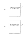
図9は、自動改札装置Aの動作を示したフローチャートであって、CPU50によって実行される手順を表している。ステップS1では、たとえば図10に示すような媒体提示を案内するメッセージが表示部4に表示され、利用者に対して、非接触カードCをかざすか非接触トークンを投入するかのいずれかの操作をうながす。図10の(a)は海外仕様における表示例、(b)は国内仕様における表示例である(以下の図11〜図15についても同様)。
【0037】
続くステップS2では、カード用アンテナ5と、非接触カードCのアンテナ34または非接触トークンTのアンテナ44との間で交信があるかどうかを監視している。この交信には、電波による無線通信のほか、光通信や電磁結合など、各種の方式を採用することができる。ステップS2で交信がない場合は(ステップS2;NO)、ステップS6へ移って、非接触トークンTが投入口6へ投入されたか否かを、センサ14(図8)の出力に基づいて判定する。非接触トークンTの投入もない場合は(ステップS6;NO)、ステップS1へ戻る。
【0038】
非接触記録媒体がカード用アンテナ5にかざされると、アンテナ5とアンテナ34または44との間で交信が行われ(ステップS2;YES)、非接触カードリーダライタ56が非接触記録媒体のデータを読み取る(ステップS3)。続いて、この読み取ったデータに含まれる媒体コードに基づいて、媒体の種類が判定される(ステップS4)。
【0039】
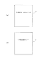
媒体の種類が非接触カードである場合は、ステップS9へ移行して、読み取られたデータが正常なデータか否かの判定が行われる。データが正常で通行許可と判定されると、たとえば図11のようなメッセージが表示部4に表示される。一方、データが正常でなく通行不可と判定されると、たとえば図12のようなメッセージが表示部4に表示される。図12は、定期券の有効期限が切れている場合の表示例である。その後、ステップS9での判定結果に従って扉の開閉を行い、通行を許可しまたは禁止する出場処理が実行される(ステップS10)。
【0040】
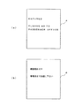
ステップS2において、カード用アンテナ5と非接触記録媒体との間で交信がない状態で(ステップS2;NO)、ステップS6で非接触トークンTが投入口6へ投入された場合は(ステップS6;YES)、トークン用アンテナ8と非接触トークンTのアンテナ44との間で交信が行われ(ステップS7)、非接触トークンリーダライタ58が非接触トークンTのデータを読み取る(ステップS8)。その後、読み取られたデータが正常なデータか否かの判定が行われる(ステップS9)。データが正常で通行許可と判定されると、前述のようにトークンTは回収箱16(図8)へ回収されるとともに、たとえば図13のようなメッセージが表示部4に表示される。一方、データが正常でなく通行不可と判定されると、前述のようにトークンTは返却口7へ返却されるとともに、たとえば図14のようなメッセージが表示部4に表示される。図14は、トークンの使用期限が切れている場合の表示例である。その後、ステップS9での判定結果に従って扉の開閉を行い、通行を許可しまたは禁止する出場処理が実行される(ステップS10)。
【0041】
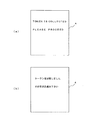
ステップS4で、媒体の種類が非接触トークンであると判定された場合、この判定は、非接触トークンTが投入口6に投入されずに、間違ってカード用アンテナ5にかざされたことを示している。この場合は、図15に示すようなメッセージを表示部4に表示して、非接触トークンを投入口へ投入するよう案内する(ステップS5)。このような案内表示をすることによって、利用者はすぐに間違いに気付き、非接触トークンTを投入口6へ投入するので、後続の利用客が待たされて列ができてしまうことが回避される。また、係員を呼ばなくても利用者は自分で処置できるため、無人化対応が可能となる。
【0042】
なお、自動改札装置Aにおいて通行禁止と判定された場合には、その判定結果が通信制御回路53(図6)を介して上位コンピュータへ送られる。上位コンピュータは駅の係員室にあって、自動改札装置Aから送られてきた情報に基づいて、トラブルの発生している改札装置の号機番号やトラブルの内容等をモニタに表示する。これによって、利用者自身でトラブルが解決できない場合には、係員が迅速に対応することができる。
【0043】
上記の例では、トークンの投入案内を表示部4に表示されるメッセージにより行っているが、このような文字での案内に代えて、あるいは文字での案内に加えて、音声により案内することも可能である。この場合は、図7に示した実施形態を採用し、音声出力部62からメッセージを音声で出力すればよい。
【0044】
また、上記の例では、非接触トークンTが投入口6に投入されたことを検知するセンサ14(図8)を設けているが、このセンサ14を省略して、トークン用アンテナ8と非接触トークンTのアンテナ44との間で交信があったことをもって、非接触トークンTの投入を検知するようにしてもよい。この場合は、図9において、ステップS6の判定内容が「非接触トークンと交信有?」に置き換わり、ステップS7が省略される。
【0045】
また、上記実施形態においては、降車駅での出場時に非接触トークンを回収する場合を例に挙げたが、本発明はこのような運用だけに限定されるものではない。たとえば、全区間が単一料金であるような場合は、乗車駅での入場時に非接触トークンを回収して入場を許可するといった運用も考えられ、本発明はこのような場合にも適用が可能である。
【0046】
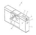
さらに、本発明の自動改札装置は、図1に示した扉式のものだけに限らず、図16に示したようなターンスタイル式の自動改札装置A´にも適用することができる。図16において、図1と同一部分には同一符号を付してある。70は本体1の内側に設けられたターンスタイルであって、通常は、内部のロック機構(図示省略)によりロックがかかって回転しないようになっており、利用者の通行を阻止している。また、カード用アンテナ5にかざされた非接触カードや、投入口6に投入された非接触トークンから読み取ったデータが正常な場合は、ロック機構のロックが解除され、ターンスタイル70は利用者が押すことで回動可能となる。このため、利用者はターンスタイル70を押しながら、1人ずつ出場することができる。
【0047】
【発明の効果】
以上のように、本発明によれば、回収すべき非接触媒体に対する専用の投入口を設けたので、利用者が間違った操作をするのを防止できるとともに、回収媒体を投入口へ投入するだけでよいので、操作が煩雑になることもない。
【図面の簡単な説明】
【図1】本発明に係る自動改札装置の一例を示した外観図である。
【図2】非接触カードの斜視図および平面図である。
【図3】非接触トークンの斜視図および平面図である。
【図4】非接触カードに内蔵されている回路装置のブロック図である。
【図5】非接触トークンに内蔵されている回路装置のブロック図である。
【図6】自動改札装置の電気的構成を示したブロック図である。
【図7】自動改札装置の他の実施形態を示したブロック図である。
【図8】投入口付近の内部機構を示した断面図である。
【図9】自動改札装置の動作を示したフローチャートである。
【図10】表示部に表示されるメッセージの例である。
【図11】表示部に表示されるメッセージの例である。
【図12】表示部に表示されるメッセージの例である。
【図13】表示部に表示されるメッセージの例である。
【図14】表示部に表示されるメッセージの例である。
【図15】表示部に表示されるメッセージの例である。
【図16】自動改札装置の他の実施形態を示した外観図である。
【符号の説明】
A 自動改札装置
C 非接触カード
T 非接触トークン
4 表示部
5 カード用アンテナ
6 投入口
7 返却口
8 トークン用アンテナ
13 シュート
15 振分部材
16 回収箱
62 音声出力部[0001]
BACKGROUND OF THE INVENTION
The present invention relates to a non-contact automatic ticket gate installed in a station or the like.
[0002]
[Prior art]
A non-contact automatic ticket gate is an automatic ticket gate that reads information recorded on a non-contact recording medium in a non-contact manner and performs permission or prohibition of passage. Conventionally, in such a non-contact automatic ticket gate, a non-contact card is generally used as a recording medium. However, contactless cards have built-in communication circuits, memory, etc., and are expensive, so they are not suitable for use as ordinary tickets that are disposed of only once, and are exclusively used for commuter passes and prepaid cards. It is used as a vehicle that can be used repeatedly.
[0003]
For this reason, ordinary tickets will be used as conventional magnetic tickets, and an automatic ticket gate dedicated to magnetic tickets and an automatic ticket gate dedicated to non-contact cards will be installed in order to support both contactless cards and magnetic tickets. Alternatively, a hybrid automatic ticket gate that can process both magnetic tickets and contactless cards is currently used. However, in the former case, two types of automatic ticket gates are required, which is uneconomical and increases the installation space. In the latter case, a mechanism and a circuit for processing both the magnetic ticket and the non-contact card are required inside the automatic ticket gate, and there is a problem that the cost is also increased.
[0004]
On the other hand, Japanese Patent Laid-Open No. 2000-331198 and Japanese Patent Laid-Open No. 9-326053 disclose non-contact cards that can be recycled by collecting ordinary tickets made of non-contact cards at the time of participation. An automatic ticket gate is described. According to this, the two types of automatic ticket gates and hybrid type automatic ticket gates as described above are no longer necessary, and even if a regular ticket is composed of a contactless card, it can be recovered and reused. There is an advantage that there is no operation cost.
[0005]
[Problems to be solved by the invention]
However, the automatic ticket gate described in each of the above publications has a problem that the user is likely to make an operation mistake at the time of participation because both a normal ticket and a commuter pass are composed of contactless cards. In other words, regular tickets that are used only once must be collected at the time of entry, so it is necessary to insert them into the card slot provided in the automatic ticket gate, whereas commuter passes etc. are repeated without being collected. Since it is used, it is necessary not to insert it into the card insertion slot but to hold it over the antenna section provided in the automatic ticket gate. However, as mentioned above, if both regular tickets and commuter passes have a card shape, the non-contact card, which is a regular ticket, may be held over the antenna section without being inserted into the card insertion slot. An error occurs that a non-contact card, which is a commuter pass, is inserted into the card insertion slot without being held over the antenna portion. When a non-contact card of an ordinary ticket is held over the antenna portion, the card cannot be collected and is prohibited from passing, and the user needs to insert the non-contact card into the card slot again. In addition, when a commuter pass is inserted into the card slot, the card is ejected to the exit in order to return the commuter pass to the user. A transport mechanism is required, and the mechanism inside the apparatus becomes complicated.
[0006]
On the other hand, in Japanese Patent Application Laid-Open No. 2000-123212, when a non-contact card held over an antenna is a ticket to be collected, it is opened after the return door is opened and the card is inserted into the return port. In addition, there is described an automatic ticket gate device that permits the passage without opening the door of the return port when the non-contact card held over the antenna portion is a ticket that cannot be collected. In this publication, a transport mechanism for transporting a non-contact card is not required, but in the case of a non-contact card to be collected such as a normal ticket, an operation of holding the card over the antenna unit when entering Then, a two-stage operation is required, that is, an operation of inserting the card into the return slot, and there is a problem that the operation becomes complicated for the user.
[0007]
The present invention solves the problems as described above, and the problem is that the user can prevent the user from performing an incorrect medium processing operation and can perform the operation itself easily. Is to provide an automatic ticket gate.
[0008]
[Means for Solving the Problems]
The non-contact type automatic ticket gate according to the present invention includes a first reading unit that reads information of a first non-contact recording medium that is a non-recovery medium, and a second non-contact recording medium that is a recovery medium. An inlet dedicated to the medium, a chute through which the second non-contact recording medium thrown into the inlet passes under its own weight, and a second reading means for reading information of the second non-contact recording medium entering the chute And a sorting member which is provided in the middle of the chute and sorts the second non-contact recording medium into the collecting side and the returning side based on the reading result of the second reading means, and is sorted to the collecting side by the sorting member A recovery box for recovering the second non-contact recording medium, and a return port for returning the second non-contact recording medium distributed to the return side by the sorting member. The second reading means reads the information of the second non-contact recording medium in a state where the second non-contact recording medium that has entered the chute is received by the sorting member and temporarily stopped. Then, if the result of reading by the second reading means is passage permission, the sorting member is rotated to the collection side, and the second non-contact recording medium received by the sorting member is placed in the collection box. to recover. Further, when the reading result by the second reading means is prohibited, the sorting member is rotated to the return side, and the second non-contact recording medium received by the sorting member is returned to the return port. return.
[0009]
Since the slot is a slot dedicated to the second non-contact recording medium, the user does not mistakenly insert the first non-contact recording medium into the slot, and the second non-contact recording medium is loaded. It comes into the mouth. This makes it possible to reliably collect the second non-contact recording medium, which is a collecting medium, and eliminates the need for a transport mechanism for returning the first non-contact recording medium that has been erroneously loaded. Further, since the second non-contact recording medium does not need to be held over the antenna portion and may be directly inserted into the insertion slot, the complexity of the two-stage operation as described in Japanese Patent Application Laid-Open No. 2000-123212 can be eliminated.
[0010]
In the present invention, the second reading unit may be provided with a shield member for preventing erroneous communication with the first non-contact recording medium.
[0011]
In an exemplary embodiment of the invention, the first contactless recording medium is composed of a contactless card, and the second contactless recording medium is composed of a contactless token. The first reading means has a card antenna that communicates with the contactless card that is held over, and the second reading means has a token antenna that communicates with the noncontact token inserted into the slot. Have. According to this, since the first non-contact recording medium is a card while the second non-contact recording medium is a coin-like token, the user can easily identify both recording media, This is more effective in preventing an erroneous operation of trying to put the first non-contact recording medium into the insertion slot or holding the second non-contact recording medium over the card antenna.
[0012]
In the present invention, it is preferable that the insertion port for the non-contact token is provided in front of the card antenna in the direction of passage (entrance direction or entrance direction). Thereby, it is possible to effectively guide the user who has the non-contact token to insert the token into the insertion slot. Moreover, it is preferable that the size of the slot for the non-contact token is set to such a dimension that the non-contact card cannot be inserted. Thereby, it is possible to eliminate any erroneous operation of erroneously inserting the non-contact card into the token slot.
[0013]
In the present invention, the non-contact token inserted into the insertion port passes by its own weight, and the non-contact token is returned to the collecting side based on the information provided in the middle of the chute and read by the token antenna. A distribution unit that distributes to the side, a collection box that collects the non-contact token distributed to the collection side by the distribution unit, and a return port that returns the non-contact token distributed to the return side by the distribution unit By providing the token, the token can be collected or returned by using the weight of the non-contact token. Thereby, it is not necessary to provide a transport mechanism for collecting and returning the non-contact token, and the structure inside the apparatus is simplified.
[0014]
Furthermore, in the present invention, when the user mistakenly holds the non-contact token over the card antenna, by guiding the user to insert the non-contact token into the slot, the user is made aware of the mistake, You can take quick measures. This guidance may be performed by displaying characters on the display unit, or may be performed by notifying by voice from the voice output unit.
[0015]
In the present invention, the above-described non-contact type automatic ticket gate has the third reading means that shares the reading of information from the first non-contact recording medium and the reading of information from the second non-contact recording medium. It is also possible to combine the two non-contact type automatic ticket gates having no inlet and collection means for the non-contact recording medium, and juxtapose both automatic ticket gates across the passage. In this case, when the user participates, in the first non-contact automatic ticket gate, the first reading means reads the information of the held first non-contact recording medium or inputs it to the insertion slot. The second reading means reads the information on the second non-contact recording medium. Further, the second non-contact recording medium is collected based on the reading result of the second reading unit. On the other hand, when the user enters, the third reading means reads the information on the held first or second non-contact recording medium in the second non-contact automatic ticket gate. At this time, the second non-contact recording medium is not collected.
[0016]
DETAILED DESCRIPTION OF THE INVENTION
FIG. 1 is an external view showing an example of an automatic ticket gate according to the present invention. Here, although two automatic ticket gates A and B are juxtaposed across the passage 9, A is the automatic ticket gate according to the embodiment of the present invention. X and Y represent the direction of travel, where X is the entry direction and Y is the entrance direction. In this example, the user enters a contactless token or contactless card over the automatic ticket gate at the boarding station, enters the contactless token into the automated ticket gate at the exit station, and holds the contactless card over the entrance. Take the case of. In this case, the automatic ticket gate device A is an automatic ticket gate device into which a contactless token of a user who participates in the X direction is inserted and a contactless card is held over. On the other hand, the automatic ticket gate device B is an automatic ticket gate device on which a contactless token or contactless card of a user who enters from the Y direction is held.
[0017]
The automatic ticket gate A includes a
[0018]
The automatic ticket gate device B is a ticket gate device having the same shape as the automatic ticket gate device A, and includes a
[0019]
2A and 2B are diagrams showing a non-contact card which is an embodiment of the first non-contact recording medium according to the present invention, where FIG. 2A is a perspective view and FIG. 2B is a plan view. The non-contact card C includes a
[0020]
3A and 3B are diagrams showing a non-contact token that is an embodiment of the second non-contact recording medium according to the present invention. FIG. 3A is a perspective view, and FIG. 3B is a plan view. Similarly to the non-contact card C, the non-contact token T includes a token
[0021]
The non-contact token T has a coin-like shape as shown in FIG. 3A, and the outer diameter L3 of the long side of the non-contact card C shown in FIG. It is shorter than any dimension of L1 and short side L2. Further, the thickness D2 of the non-contact token T is thicker than the thickness D1 of the non-contact card C. The size of the
[0022]
FIG. 4 is a block diagram of the
[0023]
FIG. 5 is a block diagram of the
[0024]
FIG. 6 is a block diagram showing an electrical configuration of the automatic ticket gate A. 50 is a CPU, 51 is a ROM that records an operation program of the
[0025]
57 is a communication control circuit for controlling transmission and reception performed with the contactless token, and 58 reads information on the contactless token via the
[0026]
FIG. 7 is a block diagram showing another embodiment of the automatic ticket gate A, where the same parts as those in FIG. In FIG. 7, an
[0027]
FIG. 8 is a sectional view showing an internal mechanism in the vicinity of the
[0028]
Next, the basic operation of the automatic ticket gate shown in FIG. 1 will be described. First, the case where a user enters from the X direction and participates will be described. When the user has a non-contact card C as a recording medium, the user holds the non-contact card C over the
[0029]
When the recording medium is a contactless token T, the user inserts the contactless token T into the
[0030]
On the other hand, when the passage is prohibited due to a lack of money, the
[0031]
A message based on the determination result of the
[0032]
Next, a case where the user enters from the Y direction in FIG. 1 and enters is described. When the recording medium possessed by the user is a contactless card C, the user holds the contactless card C over the
[0033]
As described above, in the automatic ticket gate shown in FIG. 1, the contactless card C that does not need to be collected at the time of entry can be entered by simply holding it over the
[0034]
Here, since the contactless card C and the contactless token T are different in shape and size as can be seen from FIGS. 2 and 3, the user can clearly identify them. Since the
[0035]
If a shield member (not shown) such as a ferrite core is attached to the
[0036]
FIG. 9 is a flowchart showing the operation of the automatic ticket gate A, and shows the procedure executed by the
[0037]
In the subsequent step S2, it is monitored whether or not there is communication between the
[0038]
When the non-contact recording medium is held over the
[0039]
If the type of medium is a contactless card, the process proceeds to step S9, where it is determined whether the read data is normal data. When it is determined that the data is normal and the passage is permitted, for example, a message as shown in FIG. On the other hand, when it is determined that the data is not normal and the vehicle cannot pass, for example, a message as shown in FIG. FIG. 12 is a display example when the commuter pass has expired. After that, the door is opened and closed according to the determination result in step S9, and an entry process for permitting or prohibiting passage is executed (step S10).
[0040]
In step S2, when there is no communication between the
[0041]
If it is determined in step S4 that the type of medium is a non-contact token, this determination indicates that the non-contact token T is not put into the
[0042]
If the automatic ticket gate A determines that traffic is prohibited, the determination result is sent to the host computer via the communication control circuit 53 (FIG. 6). The host computer is in the staff room of the station, and displays the number of the ticket gate apparatus in which the trouble has occurred, the content of the trouble, etc. on the monitor based on the information sent from the automatic ticket gate apparatus A. As a result, if the user cannot solve the problem himself / herself, the staff can quickly respond.
[0043]
In the above example, the token insertion guidance is performed by the message displayed on the
[0044]
In the above example, the sensor 14 (FIG. 8) for detecting that the non-contact token T has been inserted into the
[0045]
Moreover, in the said embodiment, although the case where a non-contact token was collect | recovered at the time of participation in a disembarking station was mentioned as an example, this invention is not limited only to such operation. For example, if the entire section is a single fee, it may be possible to collect the contactless token and allow entry when entering the boarding station, and the present invention can also be applied to such a case. It is.
[0046]
Furthermore, the automatic ticket gate of the present invention is not limited to the door type shown in FIG. 1, but can be applied to a turn style automatic ticket gate A ′ as shown in FIG. In FIG. 16, the same parts as those in FIG.
[0047]
【The invention's effect】
As described above, according to the present invention, since a dedicated insertion port for the non-contact medium to be collected is provided, it is possible to prevent the user from performing an incorrect operation and only to input the collection medium to the insertion port. Therefore, the operation is not complicated.
[Brief description of the drawings]
FIG. 1 is an external view showing an example of an automatic ticket gate according to the present invention.
FIG. 2 is a perspective view and a plan view of a contactless card.
FIG. 3 is a perspective view and a plan view of a non-contact token.
FIG. 4 is a block diagram of a circuit device built in a contactless card.
FIG. 5 is a block diagram of a circuit device built in a contactless token.
FIG. 6 is a block diagram showing an electrical configuration of the automatic ticket gate.
FIG. 7 is a block diagram showing another embodiment of the automatic ticket gate.
FIG. 8 is a cross-sectional view showing an internal mechanism in the vicinity of a charging port.
FIG. 9 is a flowchart showing the operation of the automatic ticket gate apparatus.
FIG. 10 is an example of a message displayed on the display unit.
FIG. 11 is an example of a message displayed on the display unit.
FIG. 12 is an example of a message displayed on the display unit.
FIG. 13 is an example of a message displayed on the display unit.
FIG. 14 is an example of a message displayed on the display unit.
FIG. 15 is an example of a message displayed on the display unit.
FIG. 16 is an external view showing another embodiment of the automatic ticket gate.
[Explanation of symbols]
A Automatic ticket gate
C contactless card
T contactless token
4 display section
5 Card antenna
6 slot
7 Return port
8 Token antenna
13 Shoot
15 Sorting member
16 Collection box
62 Audio output section
Claims (2)
非回収媒体である第1の非接触記録媒体の情報を読み取る第1の読取手段と、
回収媒体である第2の非接触記録媒体が投入される当該媒体専用の投入口と、
前記投入口に投入された第2の非接触記録媒体が自重で通過するシュートと、
前記シュート内に進入した第2の非接触記録媒体の情報を読み取る第2の読取手段と、
前記シュートの途中に設けられ、前記第2の読取手段の読み取り結果に基づいて、第2の非接触記録媒体を回収側と返却側とに振り分ける振分部材と、
前記振分部材によって回収側に振り分けられた第2の非接触記録媒体を回収する回収箱と、
前記振分部材によって返却側に振り分けられた第2の非接触記録媒体を返却する返却口とを備え、
前記第2の読取手段は、前記シュート内に進入した第2の非接触記録媒体が前記振分部材で受け止められて一旦停止した状態で、当該第2の非接触記録媒体の情報を読み取り、
前記第2の読取手段での読み取り結果が通行許可の場合は、前記振分部材を回収側に回動させて、当該振分部材で受け止められている第2の非接触記録媒体を前記回収箱に回収し、
前記第2の読取手段での読み取り結果が通行禁止の場合は、前記振分部材を返却側に回動させて、当該振分部材で受け止められている第2の非接触記録媒体を前記返却口へ返却することを特徴とする非接触式自動改札装置。A non-contact type automatic ticket gate that reads information recorded on a non-contact recording medium in a non-contact manner and permits or prohibits passage,
First reading means for reading information of a first non-contact recording medium which is a non-recovery medium;
A slot dedicated to the medium into which the second non-contact recording medium as a collection medium is loaded;
A chute through which the second non-contact recording medium introduced into the insertion port passes under its own weight;
Second reading means for reading information of a second non-contact recording medium that has entered the chute;
A sorting member that is provided in the middle of the chute and sorts the second non-contact recording medium into a collection side and a return side based on a reading result of the second reading unit;
A collection box for collecting the second non-contact recording medium distributed to the collection side by the distribution member;
A return port for returning the second non-contact recording medium distributed to the return side by the distribution member,
The second reading means reads the information of the second non-contact recording medium in a state where the second non-contact recording medium that has entered the chute is received by the sorting member and temporarily stopped,
When the passage result is read by the second reading means, the sorting member is rotated to the collecting side, and the second non-contact recording medium received by the sorting member is removed from the collecting box. To collect
When the result of reading by the second reading means is prohibited, the sorting member is rotated to the return side, and the second non-contact recording medium received by the sorting member is returned to the return port. Non-contact type automatic ticket gate, characterized by being returned to
前記第2の読取手段に、前記第1の非接触記録媒体との間で誤交信が生じるのを防止するためのシールド部材を付設したことを特徴とする非接触式自動改札装置。2. A non-contact type automatic ticket gate apparatus according to claim 1, wherein a shield member for preventing erroneous communication with the first non-contact recording medium is attached to the second reading means.
Priority Applications (3)
| Application Number | Priority Date | Filing Date | Title |
|---|---|---|---|
| JP2001176763A JP3772695B2 (en) | 2001-06-12 | 2001-06-12 | Non-contact automatic ticket gate |
| TW91110356A TW523720B (en) | 2001-06-12 | 2002-05-17 | Contactless ticket examination apparatus |
| CN02122293A CN1396534A (en) | 2001-06-12 | 2002-06-04 | Non-contact automatic ticket checking device |
Applications Claiming Priority (1)
| Application Number | Priority Date | Filing Date | Title |
|---|---|---|---|
| JP2001176763A JP3772695B2 (en) | 2001-06-12 | 2001-06-12 | Non-contact automatic ticket gate |
Publications (3)
| Publication Number | Publication Date |
|---|---|
| JP2002366991A JP2002366991A (en) | 2002-12-20 |
| JP2002366991A5 JP2002366991A5 (en) | 2005-03-10 |
| JP3772695B2 true JP3772695B2 (en) | 2006-05-10 |
Family
ID=19017701
Family Applications (1)
| Application Number | Title | Priority Date | Filing Date |
|---|---|---|---|
| JP2001176763A Expired - Fee Related JP3772695B2 (en) | 2001-06-12 | 2001-06-12 | Non-contact automatic ticket gate |
Country Status (3)
| Country | Link |
|---|---|
| JP (1) | JP3772695B2 (en) |
| CN (1) | CN1396534A (en) |
| TW (1) | TW523720B (en) |
Families Citing this family (9)
| Publication number | Priority date | Publication date | Assignee | Title |
|---|---|---|---|---|
| JP4854155B2 (en) * | 2001-09-27 | 2012-01-18 | 日本信号株式会社 | Ticket gate system using contactless token |
| CN100440259C (en) * | 2004-04-20 | 2008-12-03 | 广州市地下铁道总公司 | A token-type non-contact smart card recovery device |
| JP2006031157A (en) * | 2004-07-13 | 2006-02-02 | Omron Corp | Automatic ticket gate |
| JP2007004502A (en) * | 2005-06-24 | 2007-01-11 | Matsushita Electric Ind Co Ltd | Electronics |
| CN101694728B (en) * | 2009-10-20 | 2011-11-02 | 大连现代高技术发展有限公司 | Ticket checking machine based on RFID three-dimensional special-shaped antenna |
| CN102915567B (en) * | 2011-12-22 | 2014-09-03 | 四川久远新方向智能科技有限公司 | Finite state automatic machine based operation control method of automatic rail transit fare collection system |
| CN109215138A (en) * | 2018-07-16 | 2019-01-15 | 福建神威系统集成有限责任公司 | A kind of card reading method and system of subway gate |
| KR102166347B1 (en) * | 2020-01-15 | 2020-10-15 | 조성훈 | Control box for token |
| CN111275831B (en) * | 2020-02-11 | 2022-04-29 | 西安艾润物联网技术服务有限责任公司 | Data processing method, system and computer readable storage medium |
-
2001
- 2001-06-12 JP JP2001176763A patent/JP3772695B2/en not_active Expired - Fee Related
-
2002
- 2002-05-17 TW TW91110356A patent/TW523720B/en not_active IP Right Cessation
- 2002-06-04 CN CN02122293A patent/CN1396534A/en active Pending
Also Published As
| Publication number | Publication date |
|---|---|
| CN1396534A (en) | 2003-02-12 |
| JP2002366991A (en) | 2002-12-20 |
| TW523720B (en) | 2003-03-11 |
Similar Documents
| Publication | Publication Date | Title |
|---|---|---|
| JP2744741B2 (en) | Data processing device and card insertion part thereof | |
| JP3677778B2 (en) | Automatic ticket gate | |
| JP3772695B2 (en) | Non-contact automatic ticket gate | |
| JP2002366991A5 (en) | ||
| JP3475795B2 (en) | Automatic ticket gate | |
| KR200355455Y1 (en) | Automatic ticket checking apparatus | |
| JP3767237B2 (en) | Automatic ticket gate | |
| KR100356450B1 (en) | Automatic ticket examination system | |
| JP4635510B2 (en) | Automatic ticket gate apparatus and traffic control method | |
| JP3440477B2 (en) | Automatic ticket gate | |
| JP4703160B2 (en) | Non-contact automatic ticket gate | |
| JP3637103B2 (en) | Automatic ticket gate | |
| JPH11203513A (en) | Automatic ticket gate with multiple ticket processing function | |
| JP3777695B2 (en) | Transaction processing apparatus and automatic ticket gate | |
| JP2000353257A (en) | Managing device for train ticket or the like | |
| JP2001006006A (en) | Automatic ticket gate | |
| JP2000113239A (en) | Automatic ticket gate and automatic ticket gate method | |
| JPH0816851A (en) | Automatic ticket examination machine | |
| JP2000182107A (en) | Automatic ticket gate | |
| JPS62221795A (en) | Automatic ticket checking system using ic card | |
| JPH11191165A (en) | Automatic ticket gate | |
| JP2000242815A (en) | Automatic ticket gate and automatic ticket gate system | |
| JP2000268216A (en) | Wireless recording medium processing device, wireless recording medium processing system, automatic ticket gate, and automatic ticket gate system | |
| JPH08255271A (en) | Automatic ticket gate | |
| JP2001216541A (en) | Passenger ticket medium and automatic ticket examination machine using it |
Legal Events
| Date | Code | Title | Description |
|---|---|---|---|
| A521 | Written amendment |
Free format text: JAPANESE INTERMEDIATE CODE: A523 Effective date: 20040402 |
|
| A621 | Written request for application examination |
Free format text: JAPANESE INTERMEDIATE CODE: A621 Effective date: 20040402 |
|
| A977 | Report on retrieval |
Free format text: JAPANESE INTERMEDIATE CODE: A971007 Effective date: 20050414 |
|
| A131 | Notification of reasons for refusal |
Free format text: JAPANESE INTERMEDIATE CODE: A131 Effective date: 20050509 |
|
| A521 | Written amendment |
Free format text: JAPANESE INTERMEDIATE CODE: A523 Effective date: 20050706 |
|
| TRDD | Decision of grant or rejection written | ||
| A01 | Written decision to grant a patent or to grant a registration (utility model) |
Free format text: JAPANESE INTERMEDIATE CODE: A01 Effective date: 20060124 |
|
| A61 | First payment of annual fees (during grant procedure) |
Free format text: JAPANESE INTERMEDIATE CODE: A61 Effective date: 20060206 |
|
| R150 | Certificate of patent or registration of utility model |
Free format text: JAPANESE INTERMEDIATE CODE: R150 |
|
| FPAY | Renewal fee payment (event date is renewal date of database) |
Free format text: PAYMENT UNTIL: 20100224 Year of fee payment: 4 |
|
| LAPS | Cancellation because of no payment of annual fees |