JP3772685B2 - Rechargeable battery for electric wheelchair - Google Patents
Rechargeable battery for electric wheelchair Download PDFInfo
- Publication number
- JP3772685B2 JP3772685B2 JP2001090245A JP2001090245A JP3772685B2 JP 3772685 B2 JP3772685 B2 JP 3772685B2 JP 2001090245 A JP2001090245 A JP 2001090245A JP 2001090245 A JP2001090245 A JP 2001090245A JP 3772685 B2 JP3772685 B2 JP 3772685B2
- Authority
- JP
- Japan
- Prior art keywords
- battery
- rechargeable battery
- electric wheelchair
- rechargeable
- charging
- Prior art date
- Legal status (The legal status is an assumption and is not a legal conclusion. Google has not performed a legal analysis and makes no representation as to the accuracy of the status listed.)
- Expired - Fee Related
Links
Images


Classifications
-
- Y—GENERAL TAGGING OF NEW TECHNOLOGICAL DEVELOPMENTS; GENERAL TAGGING OF CROSS-SECTIONAL TECHNOLOGIES SPANNING OVER SEVERAL SECTIONS OF THE IPC; TECHNICAL SUBJECTS COVERED BY FORMER USPC CROSS-REFERENCE ART COLLECTIONS [XRACs] AND DIGESTS
- Y02—TECHNOLOGIES OR APPLICATIONS FOR MITIGATION OR ADAPTATION AGAINST CLIMATE CHANGE
- Y02E—REDUCTION OF GREENHOUSE GAS [GHG] EMISSIONS, RELATED TO ENERGY GENERATION, TRANSMISSION OR DISTRIBUTION
- Y02E60/00—Enabling technologies; Technologies with a potential or indirect contribution to GHG emissions mitigation
- Y02E60/10—Energy storage using batteries
-
- Y—GENERAL TAGGING OF NEW TECHNOLOGICAL DEVELOPMENTS; GENERAL TAGGING OF CROSS-SECTIONAL TECHNOLOGIES SPANNING OVER SEVERAL SECTIONS OF THE IPC; TECHNICAL SUBJECTS COVERED BY FORMER USPC CROSS-REFERENCE ART COLLECTIONS [XRACs] AND DIGESTS
- Y02—TECHNOLOGIES OR APPLICATIONS FOR MITIGATION OR ADAPTATION AGAINST CLIMATE CHANGE
- Y02T—CLIMATE CHANGE MITIGATION TECHNOLOGIES RELATED TO TRANSPORTATION
- Y02T10/00—Road transport of goods or passengers
- Y02T10/60—Other road transportation technologies with climate change mitigation effect
- Y02T10/70—Energy storage systems for electromobility, e.g. batteries
Landscapes
- Secondary Cells (AREA)
- Battery Mounting, Suspending (AREA)
- Connection Of Batteries Or Terminals (AREA)
- Electric Propulsion And Braking For Vehicles (AREA)
- Arrangement Or Mounting Of Propulsion Units For Vehicles (AREA)
Description
【0001】
【発明の属する技術分野】
本発明は、例えば歩行の不自由な人等が使用する電動車椅子に使用するものであり、特に、座席後方に搭載されたバッテリーホルダーに装填して使用する電動車椅子用充電式バッテリーに関する。
【0002】
【従来の技術】
従来、特開平8−294517号公報に記載された構成の電動車椅子がある。図11は、従来の電動車椅子の側面図、図12は、その電動車椅子に搭載されたバッテリーホルダーに充電式バッテリーを装填した状態の断面図である。
図11に示す従来の電動車椅子は、座席1が設けられたフレーム2に左右一対の車軸3,3(一方は図示しない)を固定するとともに、それら車軸3,3にハブ4を介して左右一対の車輪5,5(一方は図示しない)を回転自在に軸支してなるものである。
【0003】
上記ハブ4は、これと相対回転可能に蓋体6が連結されており、その蓋体6に、上記車輪5,5を回転駆動するためのモーター(図示しない)や、充電式バッテリー7を装填するようにしたバッテリーホルダー8が取着されている。
【0004】
バッテリーホルダー8は、充電式バッテリー7を装填するための装填口8aを上面に開設したバッテリー装填用凹部8bを形成したものであり、これの一側壁には、電源供給用端子9、充電用端子10及び放電用端子11が配設されている。
【0005】
【発明が解決しようとする課題】
しかしながら、上記従来の電動車椅子は、充電式バッテリー7の充電を、別に用意した充電器(図示しない)に移載装填して行なうことを前提としたものであり、充電作業を行なう度に、バッテリーホルダー8から充電式バッテリー7を脱抜して運搬移載する作業を行なわなければならない。
【0006】
ところが、充電式バッテリー7は、軽いものであっても3〜4kgの重量を有しているために、身体的弱者である老人や身体障害者にとって、その充電式バッテリー7の抜脱や運搬移載作業を充電の度ごとに行なうことは苦渋である。
【0007】
上記のものとは別に、バッテリーホルダー自体に充電用コネクターを配設した構成のもの(図示しない)が知られている。
この構成では、充電の度ごとに充電式バッテリーの着脱作業を行なう必要はないものの、バッテリーホルダー自体に充電用コネクターを配設しているために、上記充電用コネクターの配設位置が比較的低く、従って、当該充電用コネクターに充電器側の充電用プラグを抜き差しする作業を中腰の姿勢で行なうことになり、この場合にも身体的な負担が大きいという欠点がある。
【0008】
そこで本発明は、バッテリーホルダーに装填した状態であっても、身体的に安楽な姿勢で容易に充電作業を行うことができ、また、そのバッテリーホルダーから取り外した状態であっても充電を行なえる電動車椅子用充電式バッテリーの提供を目的としている。
【0009】
【課題を解決するための手段】
前記の目的を達成するため、本発明は次の構成を有している。
すなわち、本発明は、左右一対の主輪を軸支したフレーム上部に配設した座席後方にバッテリーホルダーが搭載されており、そのバッテリーホルダーに着脱自在に装填して使用する電動車椅子用充電式バッテリーにおいて、上記バッテリーホルダーには、正,負極の各給電端子を配設しかつ上面に装填口を開設したバッテリー装填用凹部が形成されており、上記電動車椅子用充電式バッテリーは、平断面が前後に長い長方形断面の直方体に形成され、上記バッテリーホルダーのバッテリー装填用凹部に嵌合する前記充電式バッテリーの下部に、上記各給電端子に対向する正,負極の各放電端子を配設するとともに、前記充電式バッテリーの上部に、電動車椅子の進行方向に延びる把手を形成し、上記バッテリーホルダーに設けられた前記充電式バッテリーを着脱自在にロックするロック機構のロックを解除するロック解除機構を上記把手の進行方向前側部に配設する一方、上記各放電端子とは別に充電器側の充電用プラグを連結するための充電用コネクターが前記充電式バッテリーを形成するケース本体の進行方向後ろ側面で前記長方形断面の短辺側の面に配設され、充電用プラグの抜き差しを把手に沿う前後方向で行えるように形成されていることを特徴とする電動車椅子用充電式バッテリーである。
【0012】
本発明においては、ケース本体は、左右側の分割体を互いに固着することによりなるものであり、それらの各当接縁部に、互いに当接することにより充電用プラグ差込み用開口をなす切欠きを形成している構成にできる。
【0013】
本発明においては、ケース本体内に、充電用コネクターを配設するためのコネクター室を区画形成している構成にできる。
【0014】
【発明の実施の形態】
本発明の実施の形態について、図面を参照して説明する。図1は、本発明の一実施形態に係る充電式バッテリーを装填搭載した電動車椅子の側面図、図2は、その電動車椅子の背面図、図3は、図1に包囲線Iで示す部分の拡大詳細図である。
【0015】
電動車椅子は、座席12、一対の補助輪13、一対の主輪14,14及び本発明の一実施形態に係る充電式バッテリーAを装填するためのバッテリーホルダーBを、フレーム15に適宜配設してなるものである。
【0016】
フレーム15は、左,右側枠部15L,15Rを、連結部材16,16を介して連結してなる。
左,右側枠部15L,15Rは互いに同一構造のものであり、それらは、上パイプ17,中パイプ18及び下パイプ19を上下3段にし、かつ、それらの各後端部を後パイプ20に連結したものである。
【0017】
上パイプ17は、アームレスト21を取着したほぼ水平な手掛け部17aの前半部に前縦部17bを曲成した側面横L字形のものであり、その前縦部17bの下端に上記補助輪13を配設している。
補助輪13はいわゆるキャスター式のものであり、これにより、方向転換すなわち操舵を容易に行なえるようにしている。
【0018】
中パイプ18は、水平な中間部18aの前側部に足掛け部18bを斜め下方に曲成した側面略横L字形のものであり、その足掛け部18bの下端に、この足掛け部18bを軸として折り畳められるようにした足掛け板22が取着されている。なお、23は、足掛け部18b,18b間に張架された、脚部裏側を保持するための帯状のレッグレストである。
【0019】
下パイプ19は、これの前端部を上記中パイプ18の足掛け部18bに連結したものである。
後パイプ20は、これの上端部にハンドル部20aを略水平に曲成した縦長のものであり、これの下端部側に、詳細を後述する主輪14を回動自在に支持するための車軸部20bが形成されている。
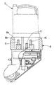
【0020】
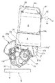
後パイプ20,20のうちの一方のものの下半部側には、図3に示すように、モーター24,減速機構及びコントローラ(図示しない)をギヤケース25に組み込んでなるパワーユニット26が固定されており、そのギヤケース25にバッテリーホルダーBを載置固定するためのホルダーブラケット27が固定されている。
【0021】
ホルダーブラケット27は、詳細を後述するバッテリーホルダーBの底面を支持する水平支持片27aと、これを上記ギヤケース25の一部に固定するための起立取付け片27bとからなる略L字形のものであり、その水平支持片27aの前端27a′を後端27a″よりもやや上方に位置させる所要角度の傾斜姿勢にして上記ギヤケース25に取り付けられている。なお、27c,27dは補強リブである。
【0022】
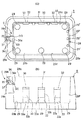
バッテリーホルダーBは、図4にも示すように、装填口28aを上面に開設したバッテリー装填用凹部28を形成した前後に長い箱形のものであり、その詳細は次の通りである。
【0023】
バッテリー装填用凹部28の底壁28bには、これの四隅と、側壁28c,28d、前後壁28e,28fのうち、側壁28d側の中央とに排出孔29…が配設されているとともに、後壁28fに沿って補助排出孔29′…が形成されている。
【0024】
上記一側壁28cには、底壁28bの辺縁部から一連に形成した3つの縦長の端子孔30〜32が互いに所定の間隔で配設されており、それらには、起立脚33aの上端部に接片33bを曲成した正面左右逆向きL字形の端子板33が配設されている。
【0025】
上記3つの端子孔30〜32のうち、前側の端子孔30に配置した端子板33は正極の給電端子、後側の端子孔32に配置した端子板33は負極の給電端子、また、それら端子孔30,32の間に形成された端子孔31に配置した端子板33は通信端子である。
【0026】
上記バッテリー装填用凹部28の前壁28eには、当該バッテリー装填用凹部28に装填されたバッテリーAをロックするロック機構Cが配設されており、その構成は次の通りである。
28hは、バッテリーA側に設けた詳細を後述するロック解除バー34を遊挿するための断面略半円形のバー遊挿溝であり、上記バッテリー装填用凹部28内に開口した状態で、装填口28aから所要の全長にして形成されている。
【0027】
上記前壁28eの上部には、バー遊挿溝28hの壁面に一端を開口した係合片摺動孔35が形成されており、その係合片摺動孔35に、係合片36とコイルスプリング37とが配設されている。
【0028】
係合片36は、これの内端に、外端上部から内端下部に向けて下向きとなるバー当接面36aを傾設した略横長直方体形のものであり、そのバー当接面36aに、上記ロック解除バー34の下端部が当接するようになっている。
コイルスプリング37は、係合片36を常時内端側に向けて弾圧するためのものであり、係合片摺動孔35の外端面と係合片36との間に配置されている。
【0029】
係合片36は、図8、図9に示すように、コイルスプリング37からの弾圧力により、バー遊挿溝28h内に突入したホルダー係止位置(イ)と、ロック解除バー34からの押下げ力によって前壁28e内に退行した係止解除位置(ロ)との間で移動自在になっている。
【0030】
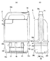
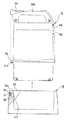
バッテリーAは、図5〜7に示すように、左右側の分割体38L,38Rを互いに固着することによりなるケース本体38内に、複数の充電池(図示しない)を相互に接続してなるバッテリーパック41を収容してなるものである。
【0031】
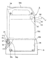
ケース本体38は側面縦長方形に形成されており、これの上部に、上記バッテリーホルダーBに対する着脱や持ち運びに供する横長で下向き略コ字形の把手38aを一体に形成したものである。
【0032】
ケース本体38の下半部寄りには、上記バッテリー装填用凹部28の装填口28aよりも一回り大きな鍔部38bが全周にわたり突設されており、その鍔部38bを境とする下側部分が、上記バッテリー装填用凹部28に嵌合されるようになっている。
また、上記鍔部38bより下側の前後壁38c,38d、側壁38e,38fのうち、前壁38cの上記係合片36に対向する部分には、その係合片36に係合する側面コ字形の係合用切欠き38gが側壁38e,38f間にわたり形成されている。
【0033】
把手38aは、これの前側上面に、切欠き38hが傾設されているとともに、この切欠き38hを被覆するように、弾性材からなるスイッチ部材39が配設されている。
この把手38aの前側、すなわち、ケース本体38の前壁38c内側には、上記ロック機構Cによる充電式バッテリーAのロックを解除するロック解除機構Dが配設されている。
【0034】
ロック解除機構Dは、上記ケース本体38の前壁38cに沿って、上記スイッチ部材39から、鍔部38b下面に形成したバー入出孔38iから突出する全長にしかつ上下移動自在なロック解除バー34と、このロック解除バー34の上部に嵌装されて、当該ロック解除バー34を常時上向きに弾圧するコイルスプリング40とからなる。
【0035】
すなわち、図7に示すように、スイッチ部材39を押し下げない状態では、ロック解除バー34は係合片36から上方に離間した待機位置(ハ)に移動されており、また、スイッチ部材39を押し下げることによって、係合片36と係合用切欠き38gとの係合を解くロック解除位置(二)に下降移動するようになっている。
【0036】
把手38aの後側、すなわち、ケース本体38の後壁38d上部には、区画壁38jによって側面略方形のコネクター室αが区画形成されているとともに、そのコネクター室αに面する後壁38d部分には、分割体38L,38Rの互いの当接縁部を方形に切り欠いてなる切欠き42′,42″を当接させてなるプラグ差込み用開口42が形成されている。
【0037】
そのコネクター室α内には、上記プラグ差込み用開口42から、水平に差し込まれた充電器側の充電用プラグ56を連結できるようにして、充電用コネクター43が配設されている。なお、44はプラグ差込み用開口42を閉塞しておくための例えばゴム製の防水キャップである。
【0038】
ケース本体38の側壁38eであって、バッテリー装填用凹部28の端子孔30〜32に配設した端子板33…に対向する位置には、これらと導通接続するための端子板45〜47が配設されている。
すなわち、上記3つの端子板45〜47のうち、前側の端子板45は正極の放電端子、後側の端子板47は負極の放電端子、また、それら端子板45,47の間に形成された端子板46は通信端子である。
【0039】
上述したバッテリーホルダーBは、前記ホルダーブラケット27に固定されることにより、前記座席12の後側において、バッテリー装填用凹部28の前壁28e側を後壁28f側よりも高くなる傾斜姿勢にして載置されている。
【0040】
ところで、前記主輪14は、図1,2に示すように、リム48及びこれに装着されたタイヤ49とからなり、放射状に配列された多数のスポーク50により、中心に配置されたハブ51に連結されており、これの中心に設けた車軸(図示しない)を介して前記車軸部20bに回転自在に取り付けられている。
【0041】
補助アーム52は、後パイプ20に突設されたブラケット53に固定された固定アーム54の下端にローラ55を軸支したものであり、後方斜め下方に延出されている。これにより、前記座席12が過度に後傾することを防ぐものである。
【0042】
座席12は、左,右側枠部15L,15Rの中パイプ18,18の中間部18a,18a間に張架された着座シート12aと、それら左,右側枠部15L,15Rの後パイプ20,20の間に張設された背もたれシート12bとからなるものである。なお、各シート12a,12bは、折り畳みに支障のないような可撓性を有しているものである。
【0043】
連結部材16,16は、上述した左,右側枠部15L,15Rの各中パイプ18,18の中間部18a,18aと、各下パイプ19の中間部分との間にX字状にクロスして架け渡されているとともに、それらは、中央でピン結合されることにより相対回動自在かつ中パイプ18,18と下パイプ19とに回動自在にピン結合されている。
【0044】
上記連結部材16,16により左,右側枠部15L,15Rを連結していることにより、それら左,右側枠部15L,15Rを互いに近付かせることにより回動し、電動車椅子全体が折り畳まれるようになっている。
【0045】
次に、上述した本発明に係る充電式バッテリーAの作用について説明する。
充電式バッテリーAをバッテリー装填用凹部28に装填することにより、その充電式バッテリーA側の端子板45〜47とバッテリーホルダーB側の端子板33…とが接触導通して、前述したパワーユニット26に対して電力が供給され得るようになる。
【0046】
充電式バッテリーAを充電する場合、本実施形態においては、次の二通りの手順による充電作業を行なえる。
まず、充電式バッテリーAをバッテリー装填用凹部28に装填した状態での充電作業を行なえる。この充電作業は、バッテリーホルダーB上に充電式バッテリーAを装填載置した状態において、その充電式バッテリーAの上部に設けた充電用コネクター43に、充電器側の充電用プラグ56を差し込むことにより行なう。
【0047】
具体的には、図8に示すように、上記充電式バッテリーAのケース本体38に設けたプラグ差込み用開口42を閉塞している防水キャップ44を開き、そのプラグ差込み用開口42に充電用プラグ56を対向させた状態に保持した後、後壁38dに接近させる方向に水平移動させて、当該プラグ差込み用開口42内に差し込むことにより、充電用プラグ56を充電用コネクター43に連結する。
このとき、充電用コネクター43は、充電式バッテリーAの上部に配設されているので、これに充電用プラグ56を連結する作業を、身体を大きく屈曲させることなく行なうことができる。
また、従来のようにバッテリーホルダーBから充電式バッテリーAを抜脱しなくてもよいので、上記の作業をさらに安楽に行なえる。
充電用コネクター43を、充電用プラグ56の抜き差しを把手に沿う前後方向で行なえるように配設しているので、その抜き差し作業を容易に行なえるとともに、両側で折り畳む構造の電動車椅子であっても、折り畳んだ状態のまま、充電用プラグ56の抜き差しを、従ってまた、充電作業を行なえる。
【0048】
上記充電式バッテリーAをバッテリー装填用凹部28から脱抜させての充電作業は、スイッチ部材39を押し下げることにより、ロック解除バー34を、これの下端部が係合片36から上方に離間した待機位置(ハ)から、図9に示すように、係合片36と係合用切欠き38gとの係合を解くロック解除位置(二)に下降移動させる。
これにより、係合片36は、図8に示すホルダー係止位置(イ)から、図9に示す係止解除位置(ロ)に移動し、これにより、充填式バッテリーAのロックが解除される。そして、そのロック解除状態のまま把手38aを把持して、図10に示すように、充電式バッテリーAを上方に引き抜くことにより、バッテリー装填用凹部28から脱抜させられる。
そして、充電式バッテリーAを所望の場所に運搬して、上記と同様の充電作業を行なう。
【0049】
なお、本発明は前述した実施形態に限るものではなく、次のような変形実施が可能である。
上記においては、充填式バッテリーに把手を設けたものを例として説明したが、必ずしも設ける必要はなく、例えばケース本体の両側壁の外面上部に、把持するための凹部を形成してもよい。
【0050】
【発明の効果】
本発明によれば、充電器側の充電用プラグを連結するための充電用コネクターを、放電端子とは別に設けているので、座席後方に配設したバッテリーホルダーに装填した状態であっても、身体的に安楽な姿勢で容易に充電作業を行うことができ、また、そのバッテリーホルダーから取り外した状態であっても充電を行なうことができる。
【0051】
また、本発明によれば、電動車椅子用充電式バッテリーの上部に、電動車椅子の進行方向に延びる把手が形成されているとともに、その把手の進行方向後側に上記充電用コネクターを配設しているので、充電用プラグの抜差し作業を容易に行なえるとともに、両側で折り畳む構造の電動車椅子であっても、折り畳んだ状態のまま、充電用プラグの抜き差しを、従ってまた、充電作業を行なうことができる。
【0052】
本発明によれば、上記把手の進行方向前側に、上記バッテリーホルダーに設けられたロック機構によるロックを解除するロック解除機構を配設しているので、充電式バッテリーの装填と脱抜、また、充電器側の充電用プラグと充電用コネクターとの連結作業を容易に行なうことができる。
【0053】
本発明によれば、充電用コネクターを、充電用プラグの抜き差しを把手に沿う前後方向で行なえるように配設しているので、その抜き差し作業を容易に行なえるとともに、両側で折り畳む構造の電動車椅子であっても、折り畳んだ状態のまま、充電用プラグの抜き差しを、従ってまた、充電作業を行なえる。
【0054】
本発明において、ケース本体を、左右側の分割体を互いに固着することによりなるものであり、それらの各当接縁部に、互いに当接することにより充電用プラグ差込み用開口をなす切欠きを形成することにより、その充電用プラグ差込み用開口の形成が容易であり、しかも、上記ケース体の成形型の構造を簡素化することができる。
【0055】
本発明において、ケース本体内に、充電用コネクターを配設するためのコネクター室を区画形成することにより、充電用プラグ差込み用開口からケース本体内に浸入した雨水や異物等が、そのケース本体内のバッテリーパックを配設した部分にまで入り込むことを防止できる。これにより、ケース本体内に浸入した雨水や異物等による故障の発生を防止できる。
【図面の簡単な説明】
【図1】本発明の一実施形態に係る充電式バッテリーを装填搭載した電動車椅子の側面図である。
【図2】同上の電動車椅子の背面図である。
【図3】図1に包囲線Iで示す部分の拡大図である。
【図4】(A)はバッテリーホルダーの平面図、(B)は、その側面図である。
【図5】(A)は本発明の一実施形態に係る充電式バッテリーの左側面図、(B)は、その背面図である。
【図6】(A)は同上の充電式バッテリーの右側面図、(B)は、その正面図である。
【図7】同上の充電式バッテリーの断面図である。
【図8】バッテリーホルダーに装填した本発明の一実施形態に係る充電式バッテリーをロックしている状態を示す側面図である。
【図9】バッテリーホルダーに装填した同上の充電式バッテリーのロックを解除する状態を示す側面図である。
【図10】バッテリーホルダーから同上の充電式バッテリーを脱抜させた状態を示す側面図である。
【図11】電動車椅子の側面図である。
【図12】同上の電動車椅子に搭載したバッテリーホルダーに充電式バッテリーを装填した状態の断面図である。
【符号の説明】
12 座席
28 バッテリー装填用凹部
28a 装填口
33 給電端子,通信端子
38 ケース本体
38a 把手
38L,38R 分割体
42 充電用プラグ差込み用開口
42′,42″ 切欠き
43 充電用コネクター
45,47 放電端子
56 充電用プラグ
A 充電式バッテリー
B バッテリーホルダー
C ロック機構
D ロック解除機構
α コネクター室[0001]
BACKGROUND OF THE INVENTION
The present invention is used for, for example, an electric wheelchair used by a person who has difficulty in walking and the like, and more particularly, relates to a rechargeable battery for an electric wheelchair that is used by being mounted on a battery holder mounted on the back of a seat.
[0002]
[Prior art]
Conventionally, there is an electric wheelchair having a configuration described in JP-A-8-294517. FIG. 11 is a side view of a conventional electric wheelchair, and FIG. 12 is a cross-sectional view of a state in which a rechargeable battery is loaded in a battery holder mounted on the electric wheelchair.
The conventional electric wheelchair shown in FIG. 11 fixes a pair of left and
[0003]
The
[0004]
The
[0005]
[Problems to be solved by the invention]
However, the conventional electric wheelchair is based on the premise that charging of the rechargeable battery 7 is performed by loading and loading into a separately prepared charger (not shown). The work of removing the rechargeable battery 7 from the
[0006]
However, since the rechargeable battery 7 has a weight of 3 to 4 kg even if it is light, the rechargeable battery 7 can be removed and transported for the elderly and physically handicapped persons. It is difficult to perform the loading work for each charge.
[0007]
In addition to the above, a battery holder (not shown) having a charging connector disposed on the battery holder itself is known.
In this configuration, although it is not necessary to attach and detach the rechargeable battery every time the battery is charged, the charging connector is disposed on the battery holder itself, so the charging connector is disposed at a relatively low position. Therefore, an operation of inserting / removing a charging plug on the charger side into / from the charging connector is performed in a middle / lower position, which also has a drawback that a physical burden is large.
[0008]
Therefore, the present invention can be easily charged in a physically comfortable posture even when loaded in the battery holder, and can be charged even when detached from the battery holder. The purpose is to provide rechargeable batteries for electric wheelchairs.
[0009]
[Means for Solving the Problems]
In order to achieve the above object, the present invention has the following configuration.
That is, according to the present invention, a battery holder is mounted on the rear side of a seat disposed on an upper part of a frame that pivotally supports a pair of left and right main wheels, and the rechargeable battery for an electric wheelchair is used by being detachably loaded in the battery holder. The battery holder is provided with a battery loading recess having positive and negative power supply terminals and a loading port formed on the upper surface . The rechargeable battery for an electric wheelchair has a front and rear cross section. The positive and negative discharge terminals facing each of the power supply terminals are arranged at the lower part of the rechargeable battery that is formed in a rectangular parallelepiped having a long rectangular cross section and fits into the battery loading recess of the battery holder, A handle extending in the traveling direction of the electric wheelchair is formed on the rechargeable battery, and the charging provided in the battery holder While the lock release mechanism for releasing the lock of the locking mechanism for locking the battery removably disposed in the traveling direction front side of the handle, for separately connecting the charging plug of the charger side and the above-mentioned discharge terminal A charging connector is arranged on the short side of the rectangular cross section at the rear side in the traveling direction of the case body forming the rechargeable battery, and is formed so that the charging plug can be inserted and removed in the front-rear direction along the handle. This is a rechargeable battery for an electric wheelchair .
[0012]
In the present invention , the case body is formed by fixing the left and right divided parts to each other, and the respective contact edge portions are provided with notches that form openings for plugging in the charging plugs by contacting each other. It can be configured.
[0013]
In the present invention , a connector chamber for disposing a charging connector can be defined in the case body.
[0014]
DETAILED DESCRIPTION OF THE INVENTION
Embodiments of the present invention will be described with reference to the drawings. 1 is a side view of an electric wheelchair loaded with a rechargeable battery according to an embodiment of the present invention, FIG. 2 is a rear view of the electric wheelchair, and FIG. 3 is a portion indicated by an encircling line I in FIG. FIG.
[0015]
In the electric wheelchair, a seat 12, a pair of
[0016]
The
The left and right
[0017]
The
The
[0018]
The
[0019]
The
The
[0020]
As shown in FIG. 3, a
[0021]
The
[0022]
As shown in FIG. 4, the battery holder B has a long box shape before and after the formation of the
[0023]
The
[0024]
In the one
[0025]
Of the three
[0026]
The
28h is a bar insertion groove having a substantially semicircular cross section for loosely inserting a
[0027]
An engagement
[0028]
The
The
[0029]
As shown in FIGS. 8 and 9 , the
[0030]
As shown in FIGS. 5 to 7, the battery A is a battery in which a plurality of rechargeable batteries (not shown) are connected to each other in a case
[0031]
The case
[0032]
Near the lower half of the
Further, of the front and
[0033]
In the
On the front side of the
[0034]
The unlocking mechanism D includes a
[0035]
That is, as shown in FIG. 7, in a state where the
[0036]
On the rear side of the
[0037]
In the connector chamber α, a charging
[0038]
On the
That is, among the three
[0039]
Above the battery holder B, by being fixed to the
[0040]
As shown in FIGS. 1 and 2, the
[0041]
The
[0042]
The seat 12 includes a seating seat 12a stretched between intermediate portions 18a and 18a of the
[0043]
The connecting
[0044]
By connecting the left and
[0045]
Next, the operation of the above-described rechargeable battery A according to the present invention will be described.
When the rechargeable battery A is loaded into the
[0046]
When charging the rechargeable battery A, in the present embodiment, the charging operation can be performed according to the following two procedures.
First, the charging operation can be performed with the rechargeable battery A loaded in the
[0047]
Specifically, as shown in FIG. 8, a
At this time, since the charging
Further, since it is not necessary to remove the rechargeable battery A from the battery holder B as in the prior art, the above work can be performed more easily.
Since the charging
[0048]
The charging operation by removing the rechargeable battery A from the
As a result, the
Then, the rechargeable battery A is transported to a desired place and the charging operation similar to the above is performed.
[0049]
Note that the present invention is not limited to the above-described embodiment, and the following modifications can be made.
In the above description, the rechargeable battery provided with a handle has been described as an example. However, it is not always necessary to provide it, and for example, a concave portion for gripping may be formed on the outer surface of both side walls of the case body.
[0050]
【The invention's effect】
According to the present invention, since the charging connector for connecting the charging plug on the charger side is provided separately from the discharge terminal, even in a state of being loaded in the battery holder disposed behind the seat, Charging can be performed easily in a physically comfortable posture, and charging can be performed even when the battery holder is detached from the battery holder.
[0051]
Further , according to the present invention, the handle extending in the traveling direction of the electric wheelchair is formed on the upper part of the rechargeable battery for the electric wheelchair, and the charging connector is disposed on the rear side in the traveling direction of the handle. Therefore, it is possible to easily insert and remove the charging plug, and even with an electric wheelchair that is folded on both sides, the charging plug can be inserted and removed in the folded state, and therefore the charging operation can be performed again. it can.
[0052]
According to the present invention, the traveling direction front side of the handle, since the disposed unlocking mechanism for releasing the lock by the lock mechanism provided in the battery holder, the loading and disengaged rechargeable battery, also, The connecting work between the charging plug on the charger side and the charging connector can be easily performed.
[0053]
According to the present invention, the charging connector is arranged so that the charging plug can be inserted and removed in the front-rear direction along the handle. Even in a wheelchair, the charging plug can be inserted and removed in the folded state, and therefore the charging operation can be performed again.
[0054]
In the present invention, the case main body is formed by fixing the left and right divided parts to each other, and a notch forming an opening for plugging in a charging plug is formed at each abutting edge portion by abutting each other. By doing so , it is easy to form the opening for plugging in the charging plug, and the structure of the molding die for the case body can be simplified.
[0055]
In the present invention, by forming a connector chamber for disposing the charging connector in the case main body, rainwater or foreign matter that has entered the case main body from the opening for plugging in the charging plug is contained in the case main body. Can be prevented from entering the part where the battery pack is provided. As a result, it is possible to prevent the occurrence of failure due to rainwater or foreign matter entering the case body.
[Brief description of the drawings]
FIG. 1 is a side view of an electric wheelchair loaded with a rechargeable battery according to an embodiment of the present invention.
FIG. 2 is a rear view of the electric wheelchair.
3 is an enlarged view of a portion indicated by a surrounding line I in FIG.
4A is a plan view of a battery holder, and FIG. 4B is a side view thereof.
5A is a left side view of a rechargeable battery according to an embodiment of the present invention, and FIG. 5B is a rear view thereof.
6A is a right side view of the above rechargeable battery, and FIG. 6B is a front view thereof.
FIG. 7 is a cross-sectional view of the above rechargeable battery.
FIG. 8 is a side view showing a state where the rechargeable battery according to the embodiment of the present invention loaded in the battery holder is locked.
FIG. 9 is a side view showing a state where the lock of the rechargeable battery loaded in the battery holder is released.
FIG. 10 is a side view showing a state where the rechargeable battery is removed from the battery holder.
FIG. 11 is a side view of the electric wheelchair.
FIG. 12 is a cross-sectional view showing a state where a rechargeable battery is loaded in a battery holder mounted on the electric wheelchair.
[Explanation of symbols]
12
Claims (3)
上記バッテリーホルダーには、正,負極の各給電端子を配設しかつ上面に装填口を開設したバッテリー装填用凹部が形成されており、
上記電動車椅子用充電式バッテリーは、平断面が前後に長い長方形断面の直方体に形成され、上記バッテリーホルダーのバッテリー装填用凹部に嵌合する前記充電式バッテリーの下部に、上記各給電端子に対向する正,負極の各放電端子を配設するとともに、前記充電式バッテリーの上部に、電動車椅子の進行方向に延びる把手を形成し、上記バッテリーホルダーに設けられた前記充電式バッテリーを着脱自在にロックするロック機構のロックを解除するロック解除機構を上記把手の進行方向前側部に配設する一方、上記各放電端子とは別に充電器側の充電用プラグを連結するための充電用コネクターが前記充電式バッテリーを形成するケース本体の進行方向後ろ側面で前記長方形断面の短辺側の面に配設され、充電用プラグの抜き差しを把手に沿う前後方向で行えるように形成されていることを特徴とする電動車椅子用充電式バッテリー。In the rechargeable battery for an electric wheelchair, a battery holder is mounted on the rear of the seat arranged on the upper part of the frame that pivotally supports a pair of left and right main wheels.
The battery holder is provided with a battery loading recess in which positive and negative feeding terminals are arranged and a loading port is opened on the upper surface.
The rechargeable battery for an electric wheelchair is formed in a rectangular parallelepiped having a long flat cross section in the front and back, and is opposed to each power supply terminal at a lower portion of the rechargeable battery that fits into a battery loading recess of the battery holder. Positive and negative discharge terminals are provided, and a handle extending in the traveling direction of the electric wheelchair is formed on the rechargeable battery, and the rechargeable battery provided in the battery holder is detachably locked. A lock releasing mechanism for releasing the lock of the lock mechanism is disposed on the front side in the traveling direction of the handle, and a charging connector for connecting a charging plug on the charger side separately from the discharge terminals is the rechargeable type. The battery is formed on the short side of the rectangular cross section on the back side in the direction of travel of the case body. Electric wheelchair Rechargeable batteries, characterized by being formed to allow in the longitudinal direction along the.
Priority Applications (1)
| Application Number | Priority Date | Filing Date | Title |
|---|---|---|---|
| JP2001090245A JP3772685B2 (en) | 2001-03-27 | 2001-03-27 | Rechargeable battery for electric wheelchair |
Applications Claiming Priority (1)
| Application Number | Priority Date | Filing Date | Title |
|---|---|---|---|
| JP2001090245A JP3772685B2 (en) | 2001-03-27 | 2001-03-27 | Rechargeable battery for electric wheelchair |
Publications (2)
| Publication Number | Publication Date |
|---|---|
| JP2002291111A JP2002291111A (en) | 2002-10-04 |
| JP3772685B2 true JP3772685B2 (en) | 2006-05-10 |
Family
ID=18945056
Family Applications (1)
| Application Number | Title | Priority Date | Filing Date |
|---|---|---|---|
| JP2001090245A Expired - Fee Related JP3772685B2 (en) | 2001-03-27 | 2001-03-27 | Rechargeable battery for electric wheelchair |
Country Status (1)
| Country | Link |
|---|---|
| JP (1) | JP3772685B2 (en) |
Families Citing this family (3)
| Publication number | Priority date | Publication date | Assignee | Title |
|---|---|---|---|---|
| JP2005287784A (en) * | 2004-03-31 | 2005-10-20 | Kokuyo Co Ltd | Office chair |
| JP5458953B2 (en) * | 2010-02-26 | 2014-04-02 | アイシン精機株式会社 | Battery structure for electric wheelchair |
| FR3056020B1 (en) * | 2016-09-13 | 2021-01-01 | Pellenc Sa | ELECTRIC BATTERY DEVICE, FOR BATTERY HOLDER |
-
2001
- 2001-03-27 JP JP2001090245A patent/JP3772685B2/en not_active Expired - Fee Related
Also Published As
| Publication number | Publication date |
|---|---|
| JP2002291111A (en) | 2002-10-04 |
Similar Documents
| Publication | Publication Date | Title |
|---|---|---|
| US10938005B2 (en) | Seat assembly or battery assembly that can be quickly exchanged, and motor vehicle, in particular motor scooter | |
| EP2403462B1 (en) | Motorized wheelchair | |
| TW533150B (en) | Electric vehicle | |
| US9522711B2 (en) | Collapsible vehicle | |
| TW201012687A (en) | Removable saddle comprising a battery for an electric cycle | |
| CN104925211A (en) | Battery Holder Device for Electric Bicycle | |
| JPH0853096A (en) | Electric bicycle | |
| WO2008133761A1 (en) | Tire-handling device | |
| CN213883888U (en) | Electric vehicle | |
| JP3772685B2 (en) | Rechargeable battery for electric wheelchair | |
| CN113811478B (en) | Stroller frames and strollers | |
| JP2000033893A (en) | On-board battery charging unit for electric assist bicycle | |
| JP2003226142A (en) | Battery replacement method for electric vehicle and battery mounting structure for electric vehicle | |
| JP7012833B2 (en) | Electric vehicle | |
| JP2001286005A (en) | Small electric four-wheeled vehicle | |
| JPH08252203A (en) | Mobile work robot | |
| CN216124700U (en) | A dismouting structure and seat for car of riding instead of walk | |
| CN115140224B (en) | A power unit locking device in a saddle-riding vehicle | |
| CN210126588U (en) | Seat for small electric vehicle and small electric vehicle | |
| CN207804507U (en) | Electric wheel-chair vehicle and its power assist apparatus | |
| JP3692456B2 (en) | wheelchair | |
| NL2007636C2 (en) | Stroller for an infant. | |
| CN221861801U (en) | Battery box and mounting structure thereof | |
| CN224084374U (en) | Animal bearing device, anchoring structure, supporting component and wheel type moving device | |
| CN213620073U (en) | Middle-mounted electric bicycle convenient for taking out battery |
Legal Events
| Date | Code | Title | Description |
|---|---|---|---|
| A621 | Written request for application examination |
Free format text: JAPANESE INTERMEDIATE CODE: A621 Effective date: 20040512 |
|
| A977 | Report on retrieval |
Free format text: JAPANESE INTERMEDIATE CODE: A971007 Effective date: 20050623 |
|
| A131 | Notification of reasons for refusal |
Free format text: JAPANESE INTERMEDIATE CODE: A131 Effective date: 20050628 |
|
| A521 | Request for written amendment filed |
Free format text: JAPANESE INTERMEDIATE CODE: A523 Effective date: 20050818 |
|
| TRDD | Decision of grant or rejection written | ||
| A01 | Written decision to grant a patent or to grant a registration (utility model) |
Free format text: JAPANESE INTERMEDIATE CODE: A01 Effective date: 20060124 |
|
| A61 | First payment of annual fees (during grant procedure) |
Free format text: JAPANESE INTERMEDIATE CODE: A61 Effective date: 20060206 |
|
| R151 | Written notification of patent or utility model registration |
Ref document number: 3772685 Country of ref document: JP Free format text: JAPANESE INTERMEDIATE CODE: R151 |
|
| S531 | Written request for registration of change of domicile |
Free format text: JAPANESE INTERMEDIATE CODE: R313532 |
|
| R350 | Written notification of registration of transfer |
Free format text: JAPANESE INTERMEDIATE CODE: R350 |
|
| FPAY | Renewal fee payment (event date is renewal date of database) |
Free format text: PAYMENT UNTIL: 20100224 Year of fee payment: 4 |
|
| FPAY | Renewal fee payment (event date is renewal date of database) |
Free format text: PAYMENT UNTIL: 20110224 Year of fee payment: 5 |
|
| FPAY | Renewal fee payment (event date is renewal date of database) |
Free format text: PAYMENT UNTIL: 20110224 Year of fee payment: 5 |
|
| FPAY | Renewal fee payment (event date is renewal date of database) |
Free format text: PAYMENT UNTIL: 20120224 Year of fee payment: 6 |
|
| FPAY | Renewal fee payment (event date is renewal date of database) |
Free format text: PAYMENT UNTIL: 20130224 Year of fee payment: 7 |
|
| FPAY | Renewal fee payment (event date is renewal date of database) |
Free format text: PAYMENT UNTIL: 20130224 Year of fee payment: 7 |
|
| FPAY | Renewal fee payment (event date is renewal date of database) |
Free format text: PAYMENT UNTIL: 20140224 Year of fee payment: 8 |
|
| LAPS | Cancellation because of no payment of annual fees |