JP3772680B2 - Taisho koto - Google Patents
Taisho koto Download PDFInfo
- Publication number
- JP3772680B2 JP3772680B2 JP2001047148A JP2001047148A JP3772680B2 JP 3772680 B2 JP3772680 B2 JP 3772680B2 JP 2001047148 A JP2001047148 A JP 2001047148A JP 2001047148 A JP2001047148 A JP 2001047148A JP 3772680 B2 JP3772680 B2 JP 3772680B2
- Authority
- JP
- Japan
- Prior art keywords
- string
- trunk body
- locking member
- strings
- string locking
- Prior art date
- Legal status (The legal status is an assumption and is not a legal conclusion. Google has not performed a legal analysis and makes no representation as to the accuracy of the status listed.)
- Expired - Fee Related
Links
- 230000037431 insertion Effects 0.000 claims description 23
- 238000003780 insertion Methods 0.000 claims description 23
- 230000000149 penetrating effect Effects 0.000 claims description 4
- 241000226585 Antennaria plantaginifolia Species 0.000 claims 2
- 238000004804 winding Methods 0.000 description 6
- 230000000694 effects Effects 0.000 description 2
- 239000002184 metal Substances 0.000 description 2
- 240000000136 Scabiosa atropurpurea Species 0.000 description 1
- 229910000831 Steel Inorganic materials 0.000 description 1
- 239000000853 adhesive Substances 0.000 description 1
- 230000001070 adhesive effect Effects 0.000 description 1
- 238000005452 bending Methods 0.000 description 1
- 230000000994 depressogenic effect Effects 0.000 description 1
- 230000005674 electromagnetic induction Effects 0.000 description 1
- 239000011810 insulating material Substances 0.000 description 1
- 238000004080 punching Methods 0.000 description 1
- 239000007787 solid Substances 0.000 description 1
- 229910001220 stainless steel Inorganic materials 0.000 description 1
- 239000010935 stainless steel Substances 0.000 description 1
- 239000010959 steel Substances 0.000 description 1
- 229920003002 synthetic resin Polymers 0.000 description 1
- 239000000057 synthetic resin Substances 0.000 description 1
- 239000002023 wood Substances 0.000 description 1
Images

Landscapes
- Stringed Musical Instruments (AREA)
Description
【0001】
【発明の属する技術分野】
本発明は大正琴に関し、特に演奏性と外観を向上させるようにした大正琴に関する。
【0002】
【従来の技術】
従来、一般の大正琴は、胴本体の上面の一端部(左端部)付近に弦の一端を係止する糸巻装置と、弦を支持する上駒を配設し、上面の他端部(右端部)付近に弦の他端を係止する弦係止部材(テールピース)と弦を支持する下駒(ブリッジ)を配設し、上駒と下駒との間の弦部分を有効振動発音部としてG音の開放弦に調律し、この有効振動発音部をキーによって押し下げてピック(義甲)で弾弦することにより、所定の音階の音を発音させるように構成されている。
【0003】
また、弦の一端を係止する弦係止部材を胴本体の右側面に固定した大正琴や、弦の高さを調整するブリッジと、弦を係止するテールピースを胴本体の上面より内部側に設けた弦楽器も知られている(特開平11−194761号公報)。
【0004】
【発明が解決しようとする課題】
しかしながら、上記した従来の大正琴と弦楽器は、いずれも以下に述べるような問題があった。すなわち、大正琴の演奏に際しては、通常右手を胴本体の右端部上面(弦係止部材より右側上面)に置いて右手指をブリッジを超える高さにまで立てて演奏するため、弦係止部材を胴本体上に配設した従来の一般の大正琴においては、弦係止部材を避けて右手を置かなければならず、それだけ右手を置くための自由な場所が制限され、演奏性という点で問題があった。これは、自由な場所が狭いと、右手が弦係止部材に当たって手の自由な動きが阻害されるからである。また、弦係止部材や弦の末端が演奏者の視界に入るため、外観がすっきりしないという問題もあった。
【0005】
上記特開平11−194761号公報に開示された弦楽器は、胴本体の上面からのブリッジの高さを低くすることができるため、右手指を高く立てて演奏する必要がないという利点があるものの、胴本体の上面にブリッジまたはブリッジとテールピースを配置するための凹部を設ける必要があるため、右手を置くための十分な場所を確保することができず、演奏性を十分には向上させることができないという問題があった。また、凹部が視認されるため、外観上好ましくないという問題があった。
【0006】
本発明は上記した従来の問題を解決するためになされたもので、その目的とするところは、簡単な構造で胴本体の上面に手を置くための十分な場所を確保することができ演奏性を向上させるとともに、弦係止部材が視認されず外観を向上させることができるようにした大正琴を提供することにある。
【0007】
【課題を解決するための手段】
上記目的を達成するために第1の発明は、上面に複数本の弦が張設される胴本体と、この胴本体の上面に配設され前記弦の各端部付近をそれぞれ支持する上駒および下駒と、前記各弦の端部を係止する糸巻装置および弦係止部材とを備え、前記胴本体の上面に手を置きながらピックで演奏する大正琴において、前記胴本体の上下面に貫通する弦挿通孔を設け、この弦挿通孔に飾り枠を嵌め込み固定し、前記飾り枠の内壁に複数の弦係止部を有する弦係止部材を配設し、前記各弦を前記飾り枠に挿入して前記弦係止部材の各弦係止部に係止したものである。
この発明においては、弦係止部材が飾り枠内に配置されているので、演奏時に右手が弦係止部材に接触したりすることがなく、胴本体の上面で演奏者から見て弦挿通孔より右側部分全体を手を置くための場所として有効に利用することができる。また、弦係止部材や弦の末端が演奏者の視界に入らず、楽器の外観をすっきりさせることができる。
【0008】
第2の発明は、上面に複数本の弦が張設される胴本体と、この胴本体の上面に配設され前記弦の各端部付近をそれぞれ支持する上駒および下駒と、前記各弦の端部を係止する糸巻装置および弦係止部材とを備え、前記胴本体の上面に手を置きながらピックで演奏する大正琴において、前記胴本体の右端部の下面側に凹部を設けるとともに、胴本体の右端部上面に前記凹部に連通する弦挿通孔を設け、この弦挿通孔に飾り枠を嵌め込み固定し、前記飾り枠の内壁および前記凹部の内壁に沿って複数の弦係止部を有する弦係止部材を配設し、前記各弦を前記飾り枠に挿入して前記弦係止部材の各弦係止部に係止したものである。
この発明においても、上記第1の発明と同様な効果が得られる。
【0010】
【発明の実施の形態】
以下、本発明を図面に示す実施の形態に基づいて詳細に説明する。
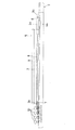
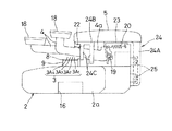
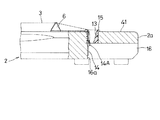
図1は本発明に係る大正琴の一実施の形態を示す平面図、図2は正面図、図3は拡大右側面図、図4は要部の拡大断面図である。本実施の形態は、電磁式ピックアップ装置を備えた電気式大正琴に適用した例を示している。なお、図2においては鍵キーの図示を省略している。
【0011】
これらの図において、全体を符号1で示す電気式大正琴は、胴本体2と、この胴本体2の上方に張設された4本の弦3と、各弦3を押え音程を決める複数の鍵キー4と、胴本体2の長手方向の中央で後方側端部(演奏者側とは反対側)の上方に配設され前記各鍵キー4の基端部4aを覆うとともに譜面台として用いられる天板5等を備えている。また、弦3の両端付近3a,3bを係止する下駒6および上駒7、指板9、各弦3の上駒7側端部が巻付けられる複数個の糸巻装置10、電磁式ピックアップ装置11、弦の3の下駒6側端部を係止する弦係止部材14等を備えている。
【0012】
前記胴本体2は、木材またはプラスチックによって断面形状が略矩形で左右方向に長い中実の板体に形成されている。また、長手方向中央部の幅が両端部より広く形成され、上面中央に前記指板9が弦3の下方に位置するように接合されている。指板9の上面には、複数本のフレット8が弦3と直交するように指板9の長手方向に所定の間隔をおいて植設されている。さらに、胴本体2の上面で右端部寄りには、下面に貫通する弦挿通孔13が形成されるとともに、前記下駒6が前記弦挿通孔13より左側に位置して配設され、この下駒6によって各弦3の一端部3aを支持し、他端部3bを前記上駒7によって支持している。上駒7は、前記指板9の上面左端部に植設されている。
【0013】
前記弦挿通孔13には、飾り枠15が嵌合され、接着剤等によって固定されている。一方、胴本体2の下面側には一端が前記弦挿通孔13に連通し他端側が前記胴本体2の右側面2aに開放する凹部16が形成されており、この凹部16の内壁面16aと前記飾り枠15の内壁面にかけて前記弦係止部材14が固定されている。弦係止部材14は、金属板の折り曲げ加工によって形成され、各弦3を係止する4つの係止部14Aを一体に備えている。
【0014】
前記弦3は、下駒6と上駒7間の弦部分がG音の開放弦となるように調律されて前記糸巻装置10と前記弦係止部材14間に張設されており、鍵キー4によって押し下げられたとき、当該鍵キー4から下駒6間の弦部分が有効振動発音部となって振動し所定の音階の音を発音する。前記糸巻装置10は、胴本体2の左端部に配設され、各弦3に所定の張力を付与している。なお、弦3は、一般的に鋼線と細巻線からなる3本の高音弦(第1〜第4弦)3A1〜3A3と、巻線からなる1本の低音弦(第4弦)3A4とで構成され、略同一高さに張設されている。
【0015】
前記鍵キー4はステンレス等の金属板を打ち抜き加工することによって製作され、指板9の上方に弦3の張設方向と直交するように、かつ前後2列に配設されている。鍵キー4の前端には合成樹脂等によって形成された音階ボタン18が一体に設けられ、基端部4aが軸19によって上下方向に回動自在に軸支されている。音階ボタン18の表面には、キー番号(図示せず)が印刷によって表示されている。また、鍵キー4は、引張りコイルばねからなる復帰用ばね20によって上方向への復帰習性が付与されることにより、非演奏時において前記天板5の前端部下面に設けたフェルト等からなる上限ストッパ22に圧接され係止されている。
【0016】
前記軸19は、前記天板5の下面に設けた逆L字形の支承部材23によって支承されている。また、この支承部材23は前記復帰用ばね20の一端を係止している。演奏時にある任意の鍵キー4の音階ボタン18を左手指で押圧して当該鍵キー4を復帰用ばね20に抗して図3において反時計方向に回動させると、当該鍵キー4の下面の長手方向中間部が全ての弦3を押圧し、当該鍵キー4に対応するフレット8の上面に押し付ける。なお、押鍵操作された鍵レバー4の音階ボタン18から指を離すと、当該鍵レバー4は復帰用ばね20の力により初期位置に回動復帰し弦3を解放する。
【0017】
前記天板5は、取付部材24を介して胴本体2の上方に略水平に配設されることにより、全ての鍵キー4の基端部4aの上方を覆っている。取付部材24は、側面視逆L字形に形成されることにより、垂直部24Aと、水平部24Bとからなり、垂直部24Aの下端部が前記胴本体2の背面に複数個の止めねじ25によって固定されている。水平部24Bは、胴本体2の上方に位置して前記天板5が固定され、前端部下面に各鍵キー4を案内し左右方向の移動を規制するガイド部24Cが一体に垂設されている。
【0018】
前記電磁式ピックアップ装置11は、前記胴本体2の上面で天板5の下駒6側端部付近に前記弦3の下方に位置するように配設されている。このピックアップ装置11は、一方の磁極(例えばN極)が弦3と対向するように配設されたマグネット26と、このマグネット26を収納する絶縁材からなるケース27と、マグネット26の周囲に巻回された図示しないピックアップコイル等を備え、弦3の振動を電気信号に変換する。すなわち、演奏時に弦3を弾いて振動させると、当該弦3とマグネット26との距離が変化するためマグネット26の磁界が変化し、電磁誘導作用によってピックアップコイルに弦振動に応じた起電力が発生する。そして、この起電力は、増幅器によって増幅され、スピーカから演奏音として発音される。なお、このような電磁式ピックアップ装置11は、従来周知である(例えば、実開平5−30896号公報、特開平1−211797号公報等)。
【0019】
さらに、前記胴本体2の上面で、ピックによって弾弦される部分(弾弦部分)40、すなわち前記下駒6とピックアップ装置11との間の部分の前縁部と後縁部には、弓による演奏時に弓毛の接触を避けるためにカット部(凹みまたはえぐり部)44,45がそれぞれ形成されている。これらのカット部44,45は、適宜の角度をもって斜面に形成されている。
【0020】
このような構造からなる大正琴1においては、弦係止部材14を胴本体2に設けた凹部16の内壁16aに配設しているので、弦挿通孔13より右方側の上面部分41に右手を置いて演奏するとき、弦係止部材14が演奏の障害になることがなく、前記上面部分41全体を右手を置く場所として有効に利用することができる。したがって、右手を置くための広くてゆったりした演奏スペースを確保でき、演奏性を向上させることができる。
【0021】
また、弦係止部材14を胴本体2内に配設しているので、演奏者の視界に入ることはない。
【0022】
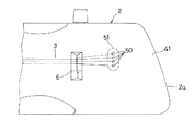
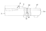
図5は本発明の他の実施の形態を示す要部の平面図、図6は一部を破断して示す正面図である。
この実施の形態は、胴本体2の上面で下駒6より右方側に下面に貫通する4つの弦挿通孔(小孔)50を各弦3毎に形成するとともに、下面側にこれらの弦挿通孔50に連通する1つの凹部51を形成している。また、各弦3の下駒6側端に通常ボールエンドと呼ばれるリング52を取付けて弦係止部材とし、このリング52を前記弦挿通孔50の下端側開口部によって係止するように構成したものである。その他の構造は上記した実施の形態と全く同一である。
【0023】
このような構造においては、各弦3毎に弦挿通孔50を形成すればよいので、大きな穴を設ける必要がなく、胴本体2の弦挿通孔50より右方側の上面部分41をより一層広く利用することができる。また、胴本体2内に弦係止部材を取付ける必要がないので、胴本体2の組立作業も容易である。
【0024】
なお、上記した実施の形態においては、いずれも電磁式ピックアップ装置11を備えた電気式大正琴1に適用した例を示したが、本発明はこれに何等限定されるものではなく、胴本体2が空洞で共鳴胴を構成する自然楽器としての大正琴にも適用することが可能である。その場合には、胴本体内に上板と下板を接続する接続部材を組込み、この接続部材に弦挿通孔を設け、弦係止部材を組込むようにすればよい。
【0025】
【発明の効果】
以上説明したように本発明に係る大正琴は、胴本体内に弦係止部材を配設したので、胴本体2の弦が挿通される弦挿通孔より右方側の上面部分に右手を置いて演奏するとき、弦係止部材が演奏の障害となることがなく、前記上面部分全体を右手を置く場所として有効に利用することができる。したがって、右手を置くための広くてゆったりした演奏スペースを確保でき、演奏性を向上させることができる。
また、楽器自体の上面構造がすっきりして弦係止部材や弦の末端が演奏者の視界に入らず、外観を向上させることができる。
【図面の簡単な説明】
【図1】 本発明に係る大正琴の一実施の形態を示す平面図である。
【図2】 正面図である。
【図3】 拡大右側面図である。
【図4】 要部の拡大断面図である。
【図5】 本発明の他の実施の形態を示す要部の平面図である。
【図6】 一部を破断して示す要部の正面図である。
【符号の説明】
1…電気式大正琴、2…胴本体、3,3A1〜3A4…弦、4…鍵キー、5…天板、6…下駒、7…上駒、9…指板、10…糸巻装置、11…電磁式ピックアップ装置、13…弦挿通孔、14…弦係止部材、16…凹部、40…胴本体の弾弦部分、50…弦挿通孔、51…凹部、52…ボールエンド。[0001]
BACKGROUND OF THE INVENTION
The present invention relates to a Taisho koto, and more particularly to a Taisho koto improved in performance and appearance.
[0002]
[Prior art]
Conventionally, a general Taisho koto has a thread winding device that locks one end of the string near the one end (left end) of the upper surface of the trunk body, and an upper piece that supports the string, and the other end (right end) of the upper surface. ) A string locking member (tail piece) that locks the other end of the string and a lower piece (bridge) that supports the string are arranged in the vicinity, and the string portion between the upper piece and the lower piece is an effective vibration sounding portion. The G tone is tuned to an open string, and the effective vibration sounding portion is depressed with a key and played with a pick (giver), thereby producing a sound of a predetermined scale.
[0003]
In addition, a Taisho koto with a string locking member that locks one end of the string fixed to the right side of the trunk body, a bridge that adjusts the height of the string, and a tail piece that locks the string are located on the inner side of the upper surface of the trunk body. Also known is a stringed musical instrument (Japanese Patent Laid-Open No. 11-194761).
[0004]
[Problems to be solved by the invention]
However, both the above-mentioned conventional Taisho koto and stringed instruments have the following problems. That is, when playing the Taisho koto, the string locking member is usually used to place the right hand on the upper surface of the right end of the trunk body (the upper surface on the right side of the string locking member) with the right hand standing up to a height exceeding the bridge. In the conventional general Taisho koto placed on the trunk body, the right hand must be placed avoiding the string locking member, the free space for placing the right hand is limited, and there is a problem in terms of performance there were. This is because if the free space is narrow, the right hand hits the string locking member and the free movement of the hand is obstructed. In addition, since the string locking member and the end of the string enter the player's field of view, there is also a problem that the appearance is not clean.
[0005]
Although the stringed instrument disclosed in the above-mentioned Japanese Patent Application Laid-Open No. 11-194661 can reduce the height of the bridge from the upper surface of the trunk body, there is an advantage that it is not necessary to play with the right finger raised, Since it is necessary to provide a recess for placing the bridge or bridge and tailpiece on the upper surface of the trunk body, it is not possible to secure a sufficient place for placing the right hand, and the performance can be improved sufficiently. There was a problem that I could not. Moreover, since a recessed part is visually recognized, there existed a problem that it was not preferable on an external appearance.
[0006]
The present invention has been made to solve the above-described conventional problems. The object of the present invention is to ensure a sufficient space for placing a hand on the upper surface of the trunk body with a simple structure. It is another object of the present invention to provide a Taisho koto that can improve the appearance without improving the appearance of the string locking member.
[0007]
[Means for Solving the Problems]
In order to achieve the above object, a first aspect of the present invention is a trunk body in which a plurality of strings are stretched on the upper surface, and an upper piece that is disposed on the upper surface of the trunk body and supports the vicinity of each end of the strings. And a lower piece, a spool device and a string locking member for locking the ends of the strings, and a Taisho koto playing with a pick while placing a hand on the upper surface of the trunk body. A string insertion hole penetrating is provided, a decorative frame is fitted and fixed to the string insertion hole, a string locking member having a plurality of string locking portions is disposed on an inner wall of the decorative frame, and each string is connected to the decorative frame. And is locked to each string locking portion of the string locking member.
In this invention, since the string locking member is arranged in the decorative frame , the right hand does not come into contact with the string locking member during performance, and the string insertion hole is viewed from the player on the upper surface of the trunk body. It is possible to effectively use the entire right part as a place for placing a hand. In addition, the string locking member and the end of the string do not enter the player's view, and the appearance of the instrument can be made clear.
[0008]
According to a second aspect of the present invention, there is provided a trunk body in which a plurality of strings are stretched on the upper surface , an upper piece and a lower piece that are disposed on the upper surface of the trunk body and respectively support the vicinity of each end of the strings, In the Taisho koto, which is provided with a spool device and a string locking member for locking the end of the string, and plays with a pick while placing a hand on the upper surface of the trunk body, a recess is provided on the lower surface side of the right end of the trunk body A string insertion hole communicating with the recess is provided on the upper surface of the right end portion of the trunk body, and a decorative frame is fitted and fixed to the string insertion hole, and a plurality of string locking portions are provided along the inner wall of the decorative frame and the inner wall of the recess. A string locking member having a string is disposed, and each string is inserted into the decorative frame and locked to each string locking portion of the string locking member .
Also in this invention, the same effect as the first invention can be obtained.
[0010]
DETAILED DESCRIPTION OF THE INVENTION
Hereinafter, the present invention will be described in detail based on embodiments shown in the drawings.
FIG. 1 is a plan view showing an embodiment of the Taisho koto according to the present invention, FIG. 2 is a front view, FIG. 3 is an enlarged right side view, and FIG. This embodiment shows an example applied to an electric Taisho koto equipped with an electromagnetic pickup device. In FIG. 2, the key and key are not shown.
[0011]
In these drawings, an electric Taisho koto, generally denoted by
[0012]
The
[0013]
A
[0014]
The
[0015]
The key 4 is manufactured by punching a metal plate such as stainless steel, and is arranged above the
[0016]
The
[0017]
The
[0018]
The electromagnetic pickup device 11 is disposed on the upper surface of the trunk
[0019]
Further, on the upper surface of the
[0020]
In the
[0021]
Further, since the
[0022]
FIG. 5 is a plan view of a main part showing another embodiment of the present invention, and FIG. 6 is a front view showing a part thereof broken.
In this embodiment, four string insertion holes (small holes) 50 penetrating the lower surface on the upper surface of the
[0023]
In such a structure, it is only necessary to form the
[0024]
In each of the above-described embodiments, an example in which the present invention is applied to the
[0025]
【The invention's effect】
As described above, the Taisho koto according to the present invention has the string locking member disposed in the trunk body, so that the right hand is placed on the upper surface portion on the right side of the string insertion hole through which the string of the
In addition, the top surface structure of the instrument itself is clear, and the string locking member and the end of the string do not enter the player's view, and the appearance can be improved.
[Brief description of the drawings]
FIG. 1 is a plan view showing an embodiment of a Taisho koto according to the present invention.
FIG. 2 is a front view.
FIG. 3 is an enlarged right side view.
FIG. 4 is an enlarged cross-sectional view of a main part.
FIG. 5 is a plan view of a main part showing another embodiment of the present invention.
FIG. 6 is a front view of the main part shown with a part broken away.
[Explanation of symbols]
DESCRIPTION OF
Claims (2)
前記胴本体の上下面に貫通する弦挿通孔を設け、この弦挿通孔に飾り枠を嵌め込み固定し、前記飾り枠の内壁に複数の弦係止部を有する弦係止部材を配設し、前記各弦を前記飾り枠に挿入して前記弦係止部材の各弦係止部に係止したことを特徴とする大正琴。A trunk body in which a plurality of strings are stretched on the upper surface, an upper piece and a lower piece that are arranged on the upper surface of the trunk body and respectively support the vicinity of the ends of the strings, and the ends of the strings. In Taisho koto, which comprises a pincushion device and a string locking member to stop, and plays with a pick while placing a hand on the upper surface of the trunk body,
A string insertion hole penetrating the upper and lower surfaces of the trunk main body is provided, a decorative frame is fitted and fixed to the string insertion hole, and a string locking member having a plurality of string locking portions is disposed on the inner wall of the decorative frame, A Taisho koto, wherein each string is inserted into the decorative frame and locked to each string locking portion of the string locking member.
前記胴本体の右端部の下面側に凹部を設けるとともに、胴本体の右端部上面に前記凹部に連通する弦挿通孔を設け、この弦挿通孔に飾り枠を嵌め込み固定し、前記飾り枠の内壁および前記凹部の内壁に沿って複数の弦係止部を有する弦係止部材を配設し、前記各弦を前記飾り枠に挿入して前記弦係止部材の各弦係止部に係止したことを特徴とする大正琴。A trunk body in which a plurality of strings are stretched on the upper surface, an upper piece and a lower piece that are arranged on the upper surface of the trunk body and respectively support the vicinity of the ends of the strings, and the ends of the strings. In Taisho koto, which comprises a pincushion device and a string locking member to stop, and plays with a pick while placing a hand on the upper surface of the trunk body,
A concave portion is provided on the lower surface side of the right end portion of the trunk body, and a string insertion hole communicating with the concave portion is provided on the upper surface of the right end portion of the trunk body, and a decorative frame is fitted and fixed to the string insertion hole, and an inner wall of the decorative frame And a string locking member having a plurality of string locking portions along the inner wall of the recess, and the strings are inserted into the decorative frame and locked to the string locking portions of the string locking member. Taisho koto characterized by that.
Priority Applications (1)
| Application Number | Priority Date | Filing Date | Title |
|---|---|---|---|
| JP2001047148A JP3772680B2 (en) | 2001-02-22 | 2001-02-22 | Taisho koto |
Applications Claiming Priority (1)
| Application Number | Priority Date | Filing Date | Title |
|---|---|---|---|
| JP2001047148A JP3772680B2 (en) | 2001-02-22 | 2001-02-22 | Taisho koto |
Publications (2)
| Publication Number | Publication Date |
|---|---|
| JP2002251181A JP2002251181A (en) | 2002-09-06 |
| JP3772680B2 true JP3772680B2 (en) | 2006-05-10 |
Family
ID=18908643
Family Applications (1)
| Application Number | Title | Priority Date | Filing Date |
|---|---|---|---|
| JP2001047148A Expired - Fee Related JP3772680B2 (en) | 2001-02-22 | 2001-02-22 | Taisho koto |
Country Status (1)
| Country | Link |
|---|---|
| JP (1) | JP3772680B2 (en) |
-
2001
- 2001-02-22 JP JP2001047148A patent/JP3772680B2/en not_active Expired - Fee Related
Also Published As
| Publication number | Publication date |
|---|---|
| JP2002251181A (en) | 2002-09-06 |
Similar Documents
| Publication | Publication Date | Title |
|---|---|---|
| JP5109666B2 (en) | String instrument tailpiece holding structure | |
| US3915049A (en) | Stringed musical instrument with aluminum made integral unit | |
| JP4251110B2 (en) | Plucked string instrument pick-up device and plucked string instrument | |
| US6723908B2 (en) | Pick guard with electronic control housing and interface for acoustic guitar | |
| JP2021085892A (en) | Electric stringed instrument | |
| EP1449199B1 (en) | Acoustic guitar with integral bridge | |
| US20070084335A1 (en) | Musical instrument with bone conduction monitor | |
| JP2025508169A (en) | String Instruments | |
| CN110462726B (en) | Body of electric guitar and electric guitar | |
| JP3772680B2 (en) | Taisho koto | |
| US4602547A (en) | Electric guitar | |
| JP7396278B2 (en) | musical instrument | |
| US20050126376A1 (en) | Invisible electromagnetic pickup for a stringed musical instrument | |
| US20230178054A1 (en) | Stringed instrument system with magnetically attached electronics module | |
| JP3312545B2 (en) | Electromagnetic pickup device for Taisho Koto | |
| JP3711886B2 (en) | Taisho koto | |
| JP3613168B2 (en) | Taisho koto | |
| US3525797A (en) | Stringed musical instrument with electromagnetic pickup also functioning as a bridge | |
| GB2265247A (en) | Bowed musical instrument | |
| US20020121174A1 (en) | Guitar neck attachment structure | |
| JP2007171682A (en) | Harp | |
| JP2012032693A (en) | Stringed instrument | |
| US5578774A (en) | Body for an electronic stringed instrument adapted to produce banjo tones | |
| JP2005283734A (en) | Bow playing type taisho harp | |
| JP4239860B2 (en) | Bowed instrument piece and bowed instrument |
Legal Events
| Date | Code | Title | Description |
|---|---|---|---|
| A977 | Report on retrieval |
Free format text: JAPANESE INTERMEDIATE CODE: A971007 Effective date: 20050715 |
|
| A131 | Notification of reasons for refusal |
Free format text: JAPANESE INTERMEDIATE CODE: A131 Effective date: 20050726 |
|
| A521 | Written amendment |
Free format text: JAPANESE INTERMEDIATE CODE: A523 Effective date: 20050914 |
|
| A02 | Decision of refusal |
Free format text: JAPANESE INTERMEDIATE CODE: A02 Effective date: 20051018 |
|
| A521 | Written amendment |
Free format text: JAPANESE INTERMEDIATE CODE: A523 Effective date: 20051109 |
|
| A911 | Transfer of reconsideration by examiner before appeal (zenchi) |
Free format text: JAPANESE INTERMEDIATE CODE: A911 Effective date: 20051222 |
|
| TRDD | Decision of grant or rejection written | ||
| A01 | Written decision to grant a patent or to grant a registration (utility model) |
Free format text: JAPANESE INTERMEDIATE CODE: A01 Effective date: 20060124 |
|
| A61 | First payment of annual fees (during grant procedure) |
Free format text: JAPANESE INTERMEDIATE CODE: A61 Effective date: 20060206 |
|
| R150 | Certificate of patent or registration of utility model |
Free format text: JAPANESE INTERMEDIATE CODE: R150 |
|
| S531 | Written request for registration of change of domicile |
Free format text: JAPANESE INTERMEDIATE CODE: R313532 |
|
| R350 | Written notification of registration of transfer |
Free format text: JAPANESE INTERMEDIATE CODE: R350 |
|
| FPAY | Renewal fee payment (event date is renewal date of database) |
Free format text: PAYMENT UNTIL: 20090224 Year of fee payment: 3 |
|
| FPAY | Renewal fee payment (event date is renewal date of database) |
Free format text: PAYMENT UNTIL: 20100224 Year of fee payment: 4 |
|
| FPAY | Renewal fee payment (event date is renewal date of database) |
Free format text: PAYMENT UNTIL: 20110224 Year of fee payment: 5 |
|
| FPAY | Renewal fee payment (event date is renewal date of database) |
Free format text: PAYMENT UNTIL: 20120224 Year of fee payment: 6 |
|
| FPAY | Renewal fee payment (event date is renewal date of database) |
Free format text: PAYMENT UNTIL: 20130224 Year of fee payment: 7 |
|
| LAPS | Cancellation because of no payment of annual fees |