JP3772671B2 - Electric tool - Google Patents
Electric tool Download PDFInfo
- Publication number
- JP3772671B2 JP3772671B2 JP2000389388A JP2000389388A JP3772671B2 JP 3772671 B2 JP3772671 B2 JP 3772671B2 JP 2000389388 A JP2000389388 A JP 2000389388A JP 2000389388 A JP2000389388 A JP 2000389388A JP 3772671 B2 JP3772671 B2 JP 3772671B2
- Authority
- JP
- Japan
- Prior art keywords
- power supply
- control circuit
- control
- motor
- power
- Prior art date
- Legal status (The legal status is an assumption and is not a legal conclusion. Google has not performed a legal analysis and makes no representation as to the accuracy of the status listed.)
- Expired - Fee Related
Links
- 238000004804 winding Methods 0.000 claims 5
Images

Landscapes
- Mechanisms For Operating Contacts (AREA)
- Charge And Discharge Circuits For Batteries Or The Like (AREA)
- Portable Power Tools In General (AREA)
Description
【0001】
【発明の属する技術分野】
本発明は、電動工具、殊に電池電源によるコードレス状態及び交流電源に電源コードを介して接続した状態の両方で作動させることができる電動工具に関するものである。
【0002】
【従来の技術】
コードレス状態で使用することができる電動工具は、一般に取り外し可能な閉鎖型電池パックをハウジングに収容保持するものとなっている。前記電池パックは、1つ又はそれ以上の電池セルを内蔵しており、電動工具の作動に必要な直流電力を供給する。
【0003】
このような装置も、通常の交流電源が得られる場所で用いる場合には、電力コードで交流電源に接続して該交流電源を外部電源として使用することができるようにしておくことが使い勝手の点で好ましい。
【0004】
【課題を解決するための手段】
しかして本発明は、直流モーターを動力装置とし、電池セルを内蔵したコードレス電力供給装置と、交流電源からの電流を直流へ変換する手段を内蔵したコード付き電力供給装置とを装置本体に選択的に電気的且つ機械的に接続する接続部を備えた電動工具であって、上記2つの電力供給装置はその供給電圧が異なっており、上記直流モータは上記2つの電力供給装置からの異なる供給電圧に夫々対応して多重巻線となった回転子巻線と、多重巻線に合わせて上記の異なる供給電圧に夫々対応した複数のブラシと、上記の異なる供給電圧に夫々対応した複数の整流子とを備えて、上記の異なる供給電圧に対して略同等のモーター駆動特性を備えており、さらにコードレス電力供給装置から供給される電力での直流モータの駆動制御のための制御回路と、コード付き電力供給装置から供給される電力での直流モータの駆動制御のための制御回路とを備え、異なる制御方式の駆動制御を行う上記両制御回路は、単一のトリガーレバーの操作で共に上記直流モータの駆動制御を行うものであることに特徴を有している。
【0005】
一方、特許公報第2859341号には、交流電源電圧を電源電圧周波数よりも高い所定周波数に変換した後に、整流された所定の直流低電圧に変換する交流/直流変換器の手段が開示されている。この手段を用いた場合、先に示した変圧器と整流器による交流/直流変換器に比べ、サイズ、重量は大幅に小型軽量化することができる。しかし、周波数変換器と降圧変換器を備えた上記方式のものにおいても、可搬式の電動工具に搭載することは、サイズ、重量、コストの面で、まだ実用水準には至っていないのが現状である。
【0006】
本発明は上記の点に鑑みて為されたものであり、大電力に対応することができるとともに電池及び交流電源の両方を電源とすることができるにもかかわらず、小型軽量とすることができ、しかも各電源による駆動時に適切なモーター制御を行うことができる電動工具を提供するにある。
【0007】
【課題を解決するための手段】
しかして本発明は、直流モーターを動力装置とし、電池セルを内蔵したコードレス電力供給装置と、交流電源からの電流を直流へ変換する手段を内蔵したコード付き電力供給装置とを装置本体に選択的に電気的且つ機械的に接続する接続部を備え、上記電力供給装置の供給電圧を異ならせると共に、異なる供給電圧に対応できるように直流モーターの回転子巻線を多重巻線とし、多重巻線に合わせた複数のブラシ、整流子を直流モータが備えており、さらにコードレス電力供給装置から供給される電力での直流モータの駆動制御のための制御回路と、コード付き電力供給装置から供給される電力での直流モータの駆動制御のための制御回路とを備え、上記両制御回路は異なる制御方式の駆動制御を行うものとなっているとともに、単一のトリガーレバーの操作で共に動作する上記両制御回路による駆動制御は略同等のモーター駆動特性(回転数−トルク特性)を得られるものとしていることに特徴を有している。
【0008】
コードレス電力供給装置からの電力は低電圧用巻線に、コード付き電力供給装置からの電力は高電圧用巻線に供給するものとすることで、コード付き電力供給装置からは高電圧直流を出力させるだけでよいようにしたものであり、また、電源の種類に応じて適切な制御方式でモーター制御を行うことができるようにしたものである。
【0009】
コードレス電力供給装置から直流モーターの低電圧用巻線に至るまでの電力供給経路と、コード付き電力供給装置から直流モータの高電圧用巻線に至るまでの電力供給経路とは分離しておくことが望ましく、この時、各電力供給経路に夫々別のスイッチを設けておく。
【0010】
コードレス電力供給装置側の制御回路はPWM制御によって駆動制御を行うものであり、コード付き電力供給装置側の制御回路は位相制御によって駆動制御を行うものであることが好ましい。
【0011】
コードレス電力供給装置側の制御回路が主制御回路と制御素子とを備える時、制御素子は電動工具ハウジングの把持部以外の箇所に配設しておくことが望ましく、さらに主制御回路と制御素子とは分離配置しておくことが望ましい。この時、コードレス電力供給装置側の制御素子は電動工具ハウジング内の風通過路内に配設しておくのが最も望ましいものとなる。
【0012】
コード付き電力供給装置側の制御回路が主制御回路と制御素子とを備える時、これら主制御回路と制御素子とはコードレス電力供給装置側の主制御回路が実装された回路基板上に実装しておくとよい。
【0013】
【発明の実施の形態】
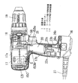
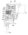
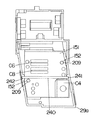
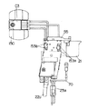
本発明の実施の形態の一例を図に基づいて説明する。図1は交流電源からの電流を直流へ変換する手段6を内蔵したコード付き電力供給装置であるACアダプターパック16を装着した状態の電動工具を示しており、図2(b)に示す複数の電池セルを内蔵したコードレス電力供給装置である電池パック15を上記ACアダプターパック16に代えて装着することができるようになっている。
【0014】
この電動工具の装置本体1のハウジング17は筒状部17aと筒状部17aの中程から下方へ突設させた把持部17bで形成される。筒状部17a内の後部には動力装置である直流モーター5が配設されると共に、その前部には直流モーター5の回転出力を減速する減速機18が配設され、筒状部17aの先端には減速機18を介して直流モーター5の出力軸5aと接続されたチャック19が配設されている。
【0015】
直流モーター5への電力の供給は、トリガーレバー21の操作によって把持部17b内に配設されたスイッチ20内の接点開閉によって行われる。このスイッチ20は電池パック15から電力供給を受けるためのターミナル22aを備えるとともに、交流電源からACアダプターパック16を介して電力供給を受けるためのターミナル23aがリード線を介して接続されたもので、これらターミナル22a,23aは夫々、電池パック15の電源ターミナル22bとACアダプターパック16の電源ターミナル23bと電気的に結合できるようになっている。
【0016】
尚、電池パック15内には、前述のように複数の電池セルが直列に収められて所定の電源電圧を発生できるようになっている。また、ACアダプターパック16内には、交流電源からの電流を整流、平滑化して直流へ変換する整流平滑回路25を配設してある。該回路25は交流電源が100Vである場合、約130V程度の直流を出力する。
【0017】
更に電池パック15及びACアダプターパック16には、装置本体1の把持部17b内へ挿入する際に機械的に結合保持するためのフック26bが設けてあり、把持部17b内面にはフック26bの受け部26aが設けてある。このように装置本体1には電池パック15及びACアダプターパック16を電気的且つ機械的に互換できる接続部が設けてある。
【0018】
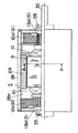
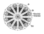
次に上記複数の供給電圧により駆動される直流モーター5について説明すると、ここで用いている直流モーター5は、直流駆動ブラシマグネットモーターであり、図17及び図18に示すように、ヨーク28の内壁28aに配設されたマグネット29の磁界の中を、シャフト30に固着された回転子鉄芯31に配された回転子巻線10にブラシ12、整流子13を介して電流が流れることにより、回転子9が回転力を持ち、軸受35に支持されて回転する構造となっているが、ここでは複数の供給電圧、即ち、低電圧及び高電圧の両方で駆動できるようにするために、低電圧用ブラシ12aと低電圧用整流子13aを介して電流が流される回転子巻線10aと、高電圧用ブラシ12bと高電圧用整流子13bを介して電流が流される回転子巻線10bの、2系統の回転子巻線10a,10bを回転子鉄芯31に配した多重巻線としている。
【0019】
前記電池パック15の直流電圧は通常2.4〜48V、電動工具用の場合、一般に7.
2V〜24V程度であり、交流電源からの整流平滑化した直流電圧は交流電源の種類によるが、100V〜300V、交流電源がAC100Vの場合、前述のように約130V程度である。このように直流モーター5の回転子巻線10を多重巻線構造とし、多重巻線に合わせた複数のブラシ12、整流子13を備えることで、電池パック15の低電圧と、交流電源からのACアダプターパック16による整流平滑化された高電圧の両方の供給電圧で駆動することが可能となる。
【0020】
そして、このように交流は高電圧直流に変換して直流モーター5に供給するものとし、直流モーター5がこの高電圧直流でも動作するように回転子巻線10bを設けていることから、ACアダプターパック16は、交流電源からの電流を整流、平滑化して直流へ変換するだけの回路25を内蔵したものでよく、この回路構成は単純であることから、サイズ的には電池パック15よりも小型軽量化が可能であり、コスト的にもキャブタイヤケーブル27のコストアップ分を足しても余りあるものとなる。
【0021】
尚、上記2系統の回転子巻線10a,10bによる夫々のモーター駆動特性(回転数−トルク特性)は、略同等にしてある。即ち、無負荷回転数は、供給電圧Vと回転子巻線の巻数nにより一義的に決まるものであり、また、停動トルクは、電池パックの場合、電池内部抵抗及び各部接触抵抗とコイル抵抗のバランスを、交流電源の場合、各部接触抵抗とコイル抵抗のバランスをコイル線径等で調整することにより同等にすることができる。従って、供給電圧の異なる複数の電力供給装置を用いても、直流モーター5の回転子9の多重巻線を適宜設計することで、装置のモーター駆動特性を常に一定に保つことが可能となる。
【0022】
また、ここではトリガーレバー21の操作で開閉されるスイッチ20として、図4に示すように、低電圧用開閉接点部20aと、高電圧用開閉接点部20bとを備えたものを用いて、電池パック15から直流モーター5の低電圧用回転子巻線10aに至る電力供給経路と、ACアダプターパック16から直流モーター5の高電圧用回転子巻線10bに至る電力供給経路とを完全に分離している。
【0023】
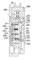
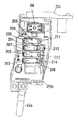
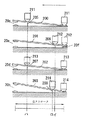
図5〜図16にここで用いているスイッチ20の詳細を示す。このスイッチ20は、上記2つの開閉接点部20a,20bに加えて、直流モーター5のスピードコントロール用の制御回路Ca,Cbをバイパスさせるための短絡用接点部20c、20dを備えるとともに、図1に示す回転方向切り換えレバー58の操作で回動するレバー55によって切り換えられる接点部50,51と、上記制御回路Ca,Cbを備えたもので、接点部20a〜20dは図8及び図9に示すように、4つの接点板200,201,202,203のシーソー動によって開閉されるものであり、トリガーレバー21と一体になっている可動板21aから図7に示すばね230によって夫々ばね付勢されている4つの滑動子211,212,213,214が、トリガーレバー21の復帰ばね250に抗した引き込み操作によって上記接点板200,201,202,203上を動く時、各接点板200,201,202,203はその支点205,206,207,208を滑動子211,212,213,214が越えた時点で反転して、接点部20a〜20dを開閉する。
【0024】
なお、支点205,206,207,208の位置は図9に示すように、同一ではなく、トリガーレバー21を引けば、まず低電圧用開閉接点部20aが閉じ、次いで高電圧用開閉接点部20bが閉じ、その後、短絡用接点部20c、20dが閉じるようになっている。また、低電圧用開閉接点部20aのための接点板201は、低電圧用開閉接点部20aを開いている時、低電圧用回転子巻線10aを短絡させるブレーキ接点20fを閉じるものとなっている。ただし、トリガーレバー21を引いた時、ブレーキ接点20fが開いた後に開閉接点部20aが閉じ、トリガーレバー21から指を離した時、開閉接点部20aが開いた後、ブレーキ接点20fが閉じるものとなっている。
【0025】
図7中の245は上記接点板200,201,202,203や接点部20a,20b,20c,20d間を仕切っている絶縁リブである。これら平行に並ぶ絶縁リブ245は単に絶縁だけでなく、可動体21aのスライドガイド溝に夫々係合して可動体21aのスライドガイドも行う。複数本の絶縁リブ245によるガイドで可動体21aが傾くことがないものである。
【0026】
トリガーレバー21の可動体21における滑動子211,212,213,214を配した側面とは反対側の面には、図12に示すように、2つの接触ばね215,216を取り付けてあるが、これら接触ばね215,216は、スイッチ20のカバー29aの内面に装着した回路基板151における抵抗パターンと接触してトリガーレバー21の引き量の検出のための可変抵抗器C6,C8を構成している。
【0027】
図12中の217はトリガーレバー21のスライドガイド用のガイドリブ、219は摺動接触面、223,224は上記復帰ばね250,250との連結用ボスである。上記摺動接触面219は、滑動子211,212,213,214を付勢するばね230の反力で、カバー29a内面及びカバー29bに取り付けたガイドピン240に接触する。摺動接触面219が接触ばね251,216の上下にあるために、上記ばね230の反力による接触ばね215,216と上記抵抗パターンとの安定した接触が得られるものである。
【0028】
さらに可動体21aに設けた突起220,221は、スイッチ20のボディ29bに可動体21を組み付けるにあたり、上記ばね230の反力でボディ29bから浮き上がってしまうことを防ぐために設けたものであり、復帰ばね250による付勢でトリガーレバー21が最も突出した状態にある時にのみ、ボディ29bと係合して浮き上がりを防ぐ。なお、トリガーレバー21を引いた時には突起220,221はボディ29bから離れるために、摺動抵抗を増やしてしまうことがない。
【0029】
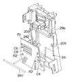
上記スピードコントロール用の制御回路Ca,Cbうち、高電圧側の制御回路Cbは、サイリスタまたはトライアックのような制御素子C4と主制御回路C2、そして前記可変抵抗器C6とからなるもので、これらは全て前記回路基板151に実装されており、位相制御によって直流モーター5のスピードコントロールを行う。
【0030】
低電圧側の制御回路CaはFETからなる制御素子C3と主制御回路C1と前記可変抵抗器C8とからなるもので、主制御回路C1と可変抵抗器C8(の抵抗パターン)は前記回路基板151に実装されてスイッチ20内に納められているものの、発熱が大きい上記制御素子C3は放熱板150に取り付けて、スイッチ20外である筒状部17a内の後端部に納め、制御素子C3の熱の影響をスイッチ20内の他の部品が受けたり、把持部17bを握る手が熱くなってしまうことがないようにしている。そして、この制御回路CaではPWM制御によって直流モーター5のスピードコントロールを行う。
【0031】
高電圧側と低電圧側とでは異なる制御を行っているが、これは各電源に応じて効率のよい駆動を行うことができるようにするためであり、また、コード付き電力供給装置からの高電圧直流電源で直流モーター5の駆動制御を行う際の制御素子を小さくすることができるようにするためである。
【0032】
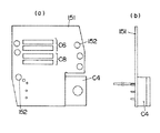
なお、上記回路基板151は、図10及び図11に示すように、カバー29aから突出する位置決め突起209,209と係合する位置決め孔152,152を備えてカバー29bの内面に位置決め配置されるとともに、可動子21aのスライドガイド用のガイドピン240を回路基板151の上からカバー29aの保持溝241,242に係合させることで、カバー29bの内面側に位置決め固定されている。
【0033】
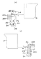
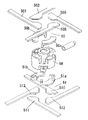
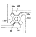
前記接点部50,51は、図15及び図16に示すように、レバー55と一体に回転する回転体56の軸方向両端面に各々2つの切り換え接点板50a,50b,51a,51bを取り付けて、回転体56の軸方向一端側に配設した4つの端子板500,501,502,503の接続関係と、回転体56の軸方向他端側に配設した4つの端子板510,511,512,513の接続関係とを回転体56の回転に伴って切り換え接点板50a,50b,51a,51bで切り換えるもので、端子板500、501は直流モーター5の高電圧用ブラシ12bに接続され、端子板502,503はACアダプターパック16入力に接続されている。また、端子板510,511は直流モーター5の低電圧用ブラシ12aに接続され、端子板502,503は電池パック15入力に接続されている。
【0034】
ここで、切り換え接点板50a,50b,51a,51bを軸方向両端面に備えた回転体56は、その軸方向両端に位置する総計8つの端子板500〜503,510〜513間に挟まれた状態で配設されることから、軸方向両端の接点圧がうち消し合うように作用して、均等な力が回転体56にかかるものであり、このために回転体56の回転動作はき
わめてスムーズなものとなっている。
【0035】
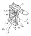
また、ここで用いている直流モーター5は、減速機18側である先端部に低電圧用ブラシ12aと低電圧用整流子13aを配置し、後端部に高電圧用ブラシ12bと高電圧用整流子13bを配置しており、内蔵する冷却用の空気吐出型ファン40は、低電圧用ブラシ12aの近傍に位置させて、図3にWで示す風の流れが得られるようにしている。発熱の大きい制御素子C3(と放熱板150)を冷やして直流モーター5内に入った風は、ファン40によって低電圧用ブラシ12a付近に吹き付けられる。低電圧用ブラシ12a側には大電流が流れることから、低電圧側の放熱がより効果的に行われるようにしているとともに、把持部17a内に配したスイッチ20との接続のためのリード線の引き回しを短くできるようにしているものである。スイッチ20内において、低電圧用の接点部20a,20cが高電圧用の接点部20b、20dよりも上方側、つまり直流モーター5側にあることも、リード線の引き回しを短くすることができる要因となっている。
【0036】
なお、ターミナル22aから接点部20a,20cへの配線は、スイッチ20のハウジングに埋め込んだ導電性金属板で行っている。また、スイッチ20における直流モーター5との接続用の端子部153a,153bをスイッチ20の上部側面に前後に離して設けているのも、各ブラシ12a,12bとの間の距離を短くするためであり、またスイッチ20の側面に設けているのは、ハウジング17にスイッチ20を組み込んだ後に直流モーター5接続用のリード線を接続することがしやすいしているためである。さらには、上記端子部153a,153bにおいて、図14から明らかなように対の端子を上下に並べているのは、上記リード線を交差させることなく接続できるようにしているためである。
【0037】
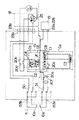
そして、ここで用いているACアダプターパック16は、電池パック15と同様に、ハウジング17の把持部17a内に差し込まれる嵌合部45の脇に5ピンのコネクターとして形成した電源ターミナル23bを配したものとしてある。もちろん、対応するターミナル23aも5ピンのコネクターとしている。このように5ピンのものを用いているのは、図4から明らかなように、開閉接点部20bを交流電源と整流平滑回路25との間に挿入して整流前の電源で開閉を行うことでアークの発生を低減するためであり、また直流モーター5のケーシングに一端を接続したアース線70を電源コード27が内蔵するアース線を通じてアース端子27aに接続することができるようにしているためである。
【0038】
また、ここで用いているACアダプターパック16は、電源コード27の引き出し部であるコードブッシュを回動自在となるように取り付けて、作業に際してコード27が邪魔にならないようにしてある。
【0039】
【発明の効果】
以上のように本発明においては、消費電力の大きい装置であっても、交流電源から直流に変換して得られる供給電圧を高電圧に設定できるため、コード付き電力供給装置の小型軽量化が可能となり、コード付き電力供給装置をコードレス電力供給装置と略相応する寸法で且つ互換性のあるものとすることができるものであり、また、コード付き電力供給装置の回路構成は単純であるため、従来の電池パックのみで作動する大電力用の可搬式モーター動力装置と比較して、コスト的にも劣らないものとすることができる。しかも、コード付き電力供給装置から電力供給する場合と、コードレス電力供給装置から電力供給する場合とで異なる制御方式の制御回路で直流モーターの駆動制御を行うことから、各電源に応じた適切な制御、たとえば高電圧の場合にはサイリスタ(またはトライアック)を用いた位相制御、低電圧の場合はFETを用いたPWM制御とすることができて、効率のよい駆動を行うことができ、単一のトリガーレバーの操作で共に動作する上記両制御回路による駆動制御が略同等のモーター駆動特性(回転数−トルク特性)を得られる上に、特にコード付き電力供給装置から電力供給する場合の制御回路素子を小さくすることができる。更にはコード付き電力供給装置とコードレス電力供給装置のいずれを使用する場合においても、モータ駆動特性が変わらない上に、トリガーレバーを操作するという操作性も変わらないことから、使用者にしてみれば電力供給装置の違いを意識せずに作業を行うことができる。
【0040】
コードレス電力供給装置から直流モーターの低電圧用巻線に至るまでの電力供給経路と
、コード付き電力供給装置から直流モータの高電圧用巻線に至るまでの電力供給経路とは分離しておけば、経路を共有した場合に問題となる絶縁距離や電流容量の点による大型化を避けることができて、小型を保つことができる。
【0041】
また、上述のようにコードレス電力供給装置側の制御回路はPWM制御によって駆動制御を行い、コード付き電力供給装置側の制御回路は位相制御によって駆動制御を行うものであることが効率の良い駆動や、制御回路素子を小さくすることができる点等で良い結果を得ることができる。
【0042】
コードレス電力供給装置側の制御回路が主制御回路と制御素子とを備える時、制御素子は電動工具ハウジングの把持部以外の箇所に配設しておくことが望ましい。上記制御素子は発熱量が大きく、把持部に配した場合、把持部を握る手が熱くなってしまう上に、放熱性が悪くなってしまうからである。
【0043】
もっとも主制御回路は発熱が殆どなく、制御素子の熱の影響を避ける意味からも、主制御回路と制御素子とは分離配置しておくことが望ましく、この時、コードレス電力供給装置側の制御素子を電動工具ハウジング内の風通過路内に配設しておくと、制御素子の冷却を好適に行うことができるものとなる。
【0044】
コード付き電力供給装置側の制御回路が主制御回路と制御素子とを備える時、これら主制御回路と制御素子とは同一の回路基板上に実装しておくことで、発熱の小さいこれら部材をリード線の引き回しを必要とすることなく配設することができる。特に、コードレス電力供給装置側の主制御回路が実装された回路基板上に実装しておくと、両電力供給装置側の制御回路を単一の基板上に実装することになり、コンパクトにまとめることができる。
【図面の簡単な説明】
【図1】 本発明の実施の形態の一例であって、ACアダプターパックを装着した状態の破断側面図である。
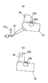
【図2】 (a)はACアダプターパックの側面図、(b)は電池パックの側面図である。
【図3】 同上の概略ブロック図である。
【図4】 同上の回路ブロック図である。
【図5】 同上のスイッチのカバーを外した状態の斜視図である。
【図6】 同上のスイッチのカバーを外した状態の側面図である。
【図7】 同上のスイッチの断面図である。
【図8】 同上のスイッチの内部構造を示す側面図である。
【図9】 同上のスイッチの動作説明図である。
【図10】 同上のスイッチのカバーの内面側の側面図である。
【図11】 同上のスイッチのカバーと回路基板の分解斜視図である。
【図12】 同上のスイッチのトリガーレバーを示すもので、(a)は左側面図、(b)は右側面図である。
【図13】 同上の回路基板を示すもので、(a)は正面図、(b)は側面図である。
【図14】 同上のスイッチアセンブリの正面図である。
【図15】 同上のスイッチの回転方向切り換え接点部の分解斜視図である。
【図16】 同上のスイッチの回転方向切り換え接点部の平面図である。
【図17】 同上の直流モーターの破断側面図である。
【図18】 同上の直流モーターの横断面図である。
【符号の説明】
1 装置本体
5 直流モーター
15 コードレス電力供給装置
16 コード付き電力供給装置[0001]
BACKGROUND OF THE INVENTION
The present invention relates to a power tool, particularly a power tool that can be operated both in a cordless state by a battery power source and in a state in which the power source is connected to an AC power source via a power cord.
[0002]
[Prior art]
A power tool that can be used in a cordless state generally accommodates and holds a detachable closed battery pack in a housing. The battery pack incorporates one or more battery cells and supplies DC power necessary for the operation of the power tool.
[0003]
When such an apparatus is also used in a place where a normal AC power source can be obtained, it is convenient to connect the AC power source with a power cord so that the AC power source can be used as an external power source. Is preferable.
[0004]
[Means for Solving the Problems]
Therefore, the present invention selectively selects a cordless power supply device including a battery cell and a cordless power supply device including a battery cell and a corded power supply device including a means for converting a current from an AC power source into a DC as a power device. With electrical and mechanical connectionsA power tool,the aboveTwoPower supplyIs thatSupply voltageAre different,The DC motor includes a rotor winding having multiple windings corresponding to different supply voltages from the two power supply devices, and a plurality of brushes corresponding to the different supply voltages in accordance with the multiple windings. And a plurality of commutators respectively corresponding to the different supply voltages, and having substantially the same motor drive characteristics for the different supply voltages,Furthermore, a control circuit for driving control of the DC motor with the power supplied from the cordless power supply device, and a control circuit for driving control of the DC motor with the power supplied from the corded power supply device,Perform drive control of different control methodsBoth control circuits are,By operating a single trigger leverBoth control the drive of the DC motor.It has a special feature.
[0005]
On the other hand, Japanese Patent Publication No. 2859341 discloses means for an AC / DC converter that converts an AC power supply voltage into a predetermined frequency higher than the power supply voltage frequency, and then converts it into a rectified predetermined DC low voltage. . When this means is used, the size and weight can be significantly reduced in size and weight as compared with the AC / DC converter using the transformer and rectifier described above. However, even in the above-described method including a frequency converter and a step-down converter, mounting on a portable power tool has not yet reached a practical level in terms of size, weight, and cost. is there.
[0006]
The present invention has been made in view of the above points, and can be made small and light despite being able to handle large power and use both a battery and an AC power supply as a power source. In addition, it is an object of the present invention to provide an electric tool capable of performing appropriate motor control when driven by each power source.
[0007]
[Means for Solving the Problems]
Therefore, the present invention selectively selects a cordless power supply device including a battery cell and a cordless power supply device including a battery cell and a corded power supply device including a means for converting a current from an AC power source into a DC as a power device. And a connecting portion for electrically and mechanically connecting to the power supply device, the supply voltage of the power supply device is different, and the rotor winding of the DC motor is a multiple winding so that the different supply voltage can be handled. The DC motor is provided with a plurality of brushes and commutators matched to the above, and is further supplied from a cordless power supply device and a control circuit for driving control of the DC motor with power supplied from the cordless power supply device And a control circuit for driving control of the DC motor with electric power, and both the control circuits perform driving control of different control methods.At the same time, the drive control by the above two control circuits operating together by operating a single trigger lever is supposed to obtain substantially equivalent motor drive characteristics (rotation speed-torque characteristics).It has a special feature.
[0008]
The power from the cordless power supply device is supplied to the low voltage winding, and the power from the corded power supply device is supplied to the high voltage winding. The motor control can be performed by an appropriate control method according to the type of the power source.
[0009]
Separate the power supply path from the cordless power supply device to the DC motor low voltage winding and the power supply route from the corded power supply device to the DC motor high voltage winding. In this case, a separate switch is provided for each power supply path.
[0010]
The control circuit on the cordless power supply apparatus side performs drive control by PWM control, and the control circuit on the corded power supply apparatus side preferably performs drive control by phase control.
[0011]
When the control circuit on the cordless power supply apparatus side includes the main control circuit and the control element, it is desirable that the control element is disposed at a place other than the grip portion of the electric tool housing, and the main control circuit, the control element, Are preferably arranged separately. At this time, it is most desirable to arrange the control element on the cordless power supply apparatus side in the wind passage in the electric tool housing.
[0012]
When the control circuit on the corded power supply device side includes a main control circuit and a control element, the main control circuit and the control element are mounted on a circuit board on which the main control circuit on the cordless power supply device side is mounted. It is good to leave.
[0013]
DETAILED DESCRIPTION OF THE INVENTION
An example of an embodiment of the present invention will be described with reference to the drawings. FIG. 1 shows an electric tool in a state in which an
[0014]
The
[0015]
Supply of electric power to the
[0016]
In the
[0017]
Further, the
[0018]
Next, the
[0019]
The DC voltage of the
The DC voltage rectified and smoothed from the AC power supply is about 2V to 24V, depending on the type of AC power supply, but when the AC power supply is AC100V, it is about 130V as described above. In this way, the rotor winding 10 of the
[0020]
In this way, AC is converted to high voltage DC and supplied to the
[0021]
The motor drive characteristics (rotational speed-torque characteristics) of the two systems of
[0022]
Here, as the
[0023]
5 to 16 show the details of the
[0024]
As shown in FIG. 9, the positions of the
[0025]
[0026]
As shown in FIG. 12, two contact springs 215 and 216 are attached to the surface of the
[0027]
In FIG. 12,
[0028]
Further, the
[0029]
Among the control circuits Ca and Cb for speed control, the control circuit Cb on the high voltage side is composed of a control element C4 such as a thyristor or triac, a main control circuit C2, and the variable resistor C6. All are mounted on the
[0030]
The control circuit Ca on the low voltage side includes a control element C3 composed of an FET, a main control circuit C1, and the variable resistor C8. The main control circuit C1 and the variable resistor C8 (the resistance pattern thereof) are the
[0031]
Different control is performed on the high-voltage side and the low-voltage side. This is to enable efficient driving according to each power source, and also from the corded power supply device. This is because it is possible to reduce the size of the control element when the drive control of the
[0032]
As shown in FIGS. 10 and 11, the
[0033]
As shown in FIGS. 15 and 16, the
[0034]
Here, the rotating
It has become so smooth.
[0035]
Further, the
[0036]
The wiring from the terminal 22a to the
[0037]
In the
[0038]
Further, the
[0039]
【The invention's effect】
As described above, according to the present invention, even with a device that consumes a large amount of power, the supply voltage obtained by converting the AC power source into DC can be set to a high voltage, so that the corded power supply device can be reduced in size and weight. Therefore, the corded power supply device can be made to have a size substantially equivalent to that of the cordless power supply device and be compatible, and the circuit configuration of the corded power supply device is simple. Compared with a high-power portable motor power device that operates only with a battery pack, the cost can be reduced. In addition, the DC motor drive control is performed by a control circuit with a different control method for supplying power from a corded power supply device and for supplying power from a cordless power supply device, so appropriate control according to each power source For example, phase control using a thyristor (or triac) in the case of a high voltage, PWM control using an FET in the case of a low voltage, and efficient driving can be performed.The drive control by the above two control circuits operating together by the operation of a single trigger lever can obtain a substantially equivalent motor drive characteristic (rotation speed-torque characteristic)In particular, it is possible to reduce the size of the control circuit element when power is supplied from the corded power supply device.Furthermore, when using either a corded power supply device or a cordless power supply device, the motor drive characteristics do not change and the operability of operating the trigger lever does not change. Work can be done without being aware of the difference in power supply devices.
[0040]
The power supply path from the cordless power supply device to the low voltage winding of the DC motor
If it is separated from the power supply path from the power supply device with cord to the high voltage winding of the DC motor, the size will be increased due to insulation distance and current capacity, which becomes a problem when the path is shared. Can be avoided and keep small.
[0041]
As described above, the control circuit on the cordless power supply apparatus side performs drive control by PWM control, and the control circuit on the corded power supply apparatus side performs drive control by phase control. Good results can be obtained in that the control circuit element can be made smaller.
[0042]
When the control circuit on the cordless power supply apparatus side includes the main control circuit and the control element, it is desirable that the control element is disposed at a place other than the grip portion of the electric tool housing. This is because the control element generates a large amount of heat, and when it is arranged on the gripping part, the hand gripping the gripping part becomes hot and the heat dissipation becomes worse.
[0043]
However, it is desirable that the main control circuit and the control element are separated from each other in order to avoid the influence of heat of the control element because the main control circuit hardly generates heat. At this time, the control element on the cordless power supply apparatus side is desirable. Is disposed in the wind passage in the electric tool housing, the control element can be suitably cooled.
[0044]
When the control circuit on the corded power supply device side includes a main control circuit and a control element, the main control circuit and the control element are mounted on the same circuit board, so that these members with low heat generation are lead. Arrangement can be made without the need for wiring. In particular, if it is mounted on the circuit board on which the main control circuit on the cordless power supply device side is mounted, the control circuit on both power supply devices side will be mounted on a single substrate, and it will be compactly integrated. Can do.
[Brief description of the drawings]
FIG. 1 is an example of an embodiment of the present invention, and is a cutaway side view with an AC adapter pack attached.
2A is a side view of an AC adapter pack, and FIG. 2B is a side view of a battery pack.
FIG. 3 is a schematic block diagram of the above.
FIG. 4 is a circuit block diagram of the above.
FIG. 5 is a perspective view of the switch with the cover removed.
FIG. 6 is a side view of the above switch with the cover removed.
FIG. 7 is a sectional view of the switch.
FIG. 8 is a side view showing the internal structure of the switch.
FIG. 9 is an operation explanatory diagram of the switch.
FIG. 10 is a side view of the inner surface side of the cover of the switch.
FIG. 11 is an exploded perspective view of the cover of the switch and the circuit board.
FIGS. 12A and 12B show a trigger lever of the switch, wherein FIG. 12A is a left side view and FIG. 12B is a right side view.
FIGS. 13A and 13B show the same circuit board, in which FIG. 13A is a front view and FIG. 13B is a side view.
FIG. 14 is a front view of the switch assembly.
FIG. 15 is an exploded perspective view of a rotation direction switching contact portion of the switch.
FIG. 16 is a plan view of a rotation direction switching contact portion of the switch.
FIG. 17 is a cutaway side view of the direct current motor.
FIG. 18 is a cross-sectional view of the direct current motor.
[Explanation of symbols]
1 Main unit
5 DC motor
15 Cordless power supply device
16 Power supply device with cord
Claims (7)
Priority Applications (1)
| Application Number | Priority Date | Filing Date | Title |
|---|---|---|---|
| JP2000389388A JP3772671B2 (en) | 1999-12-22 | 2000-12-21 | Electric tool |
Applications Claiming Priority (3)
| Application Number | Priority Date | Filing Date | Title |
|---|---|---|---|
| JP11-365571 | 1999-12-22 | ||
| JP36557199 | 1999-12-22 | ||
| JP2000389388A JP3772671B2 (en) | 1999-12-22 | 2000-12-21 | Electric tool |
Related Child Applications (1)
| Application Number | Title | Priority Date | Filing Date |
|---|---|---|---|
| JP2004162357A Division JP2004255569A (en) | 1999-12-22 | 2004-05-31 | Power tool |
Publications (2)
| Publication Number | Publication Date |
|---|---|
| JP2001239474A JP2001239474A (en) | 2001-09-04 |
| JP3772671B2 true JP3772671B2 (en) | 2006-05-10 |
Family
ID=26581680
Family Applications (1)
| Application Number | Title | Priority Date | Filing Date |
|---|---|---|---|
| JP2000389388A Expired - Fee Related JP3772671B2 (en) | 1999-12-22 | 2000-12-21 | Electric tool |
Country Status (1)
| Country | Link |
|---|---|
| JP (1) | JP3772671B2 (en) |
Families Citing this family (9)
| Publication number | Priority date | Publication date | Assignee | Title |
|---|---|---|---|---|
| JP4879570B2 (en) * | 2005-12-01 | 2012-02-22 | 日本電産テクノモータホールディングス株式会社 | Trigger switch for electric tools |
| JP5080588B2 (en) * | 2006-11-17 | 2012-11-21 | イリノイ トゥール ワークス インコーポレイティド | Power conversion and software lockout for corded power nailers |
| JP2008173716A (en) * | 2007-01-18 | 2008-07-31 | Max Co Ltd | Electric power tool having brushless motor |
| JP2009240022A (en) * | 2008-03-26 | 2009-10-15 | Nidec Shibaura Corp | Motor controller, brushless motor, and power tool |
| JP5512110B2 (en) * | 2008-09-26 | 2014-06-04 | 株式会社マキタ | Electric tool |
| JP5834186B2 (en) * | 2013-12-20 | 2015-12-16 | パナソニックIpマネジメント株式会社 | Power supply control device |
| JP2018507728A (en) * | 2015-02-27 | 2018-03-22 | エシコン エルエルシーEthicon LLC | Power adapter for surgical instruments |
| WO2022242728A1 (en) * | 2021-05-20 | 2022-11-24 | 格力博(江苏)股份有限公司 | Power device and electric tool |
| DE102023201438A1 (en) * | 2023-02-20 | 2024-08-22 | Robert Bosch Gesellschaft mit beschränkter Haftung | Electric motor and power tool with an electric motor |
-
2000
- 2000-12-21 JP JP2000389388A patent/JP3772671B2/en not_active Expired - Fee Related
Also Published As
| Publication number | Publication date |
|---|---|
| JP2001239474A (en) | 2001-09-04 |
Similar Documents
| Publication | Publication Date | Title |
|---|---|---|
| US20130326898A1 (en) | Light efficient hair dryer | |
| CN108400629B (en) | Battery | |
| EP1451917B1 (en) | Handheld generator | |
| JP3772671B2 (en) | Electric tool | |
| US20100007293A1 (en) | Programmable power-control circuit and methods of operation | |
| EP1043829B1 (en) | Hybrid AC/DC motor | |
| JP2001245462A (en) | Portable motor power device and power tool equipped with it | |
| WO1995026069A1 (en) | Electric machine with a transformer having a rotating component | |
| EP2995427B1 (en) | Electric tool | |
| JPH03503834A (en) | Power operated device with cooler | |
| EP0836763A1 (en) | Switched reluctance electric machine system | |
| US10868462B2 (en) | Power tool | |
| JP2004255569A (en) | Power tool | |
| JP2001037531A (en) | Hair drier | |
| US3820000A (en) | Method and transformer/motor for charging batteries | |
| EP1510147B1 (en) | Multiple-setting portable dryer and circuit designs thereof | |
| US7345437B2 (en) | Rechargeable vacuum with reduced AC voltage | |
| EP1110678A1 (en) | Portable motor power device | |
| US3316417A (en) | Electrical power and control mechanism for electrical appliances | |
| JP2001179658A (en) | Power tool | |
| KR20190118885A (en) | Exercise apparatus and load module therefor | |
| CA2225749C (en) | Switched reluctance electric machine system | |
| US6873792B2 (en) | Multiple-setting portable dryer and circuit designs thereof | |
| JP3731541B2 (en) | Cordless equipment | |
| EP1806831A2 (en) | Portable air-flow appliance with dual electrical power supply |
Legal Events
| Date | Code | Title | Description |
|---|---|---|---|
| A131 | Notification of reasons for refusal |
Free format text: JAPANESE INTERMEDIATE CODE: A131 Effective date: 20040330 |
|
| A521 | Written amendment |
Free format text: JAPANESE INTERMEDIATE CODE: A523 Effective date: 20040531 |
|
| A02 | Decision of refusal |
Free format text: JAPANESE INTERMEDIATE CODE: A02 Effective date: 20041221 |
|
| A521 | Written amendment |
Free format text: JAPANESE INTERMEDIATE CODE: A523 Effective date: 20050221 |
|
| A911 | Transfer to examiner for re-examination before appeal (zenchi) |
Free format text: JAPANESE INTERMEDIATE CODE: A911 Effective date: 20050224 |
|
| A131 | Notification of reasons for refusal |
Free format text: JAPANESE INTERMEDIATE CODE: A131 Effective date: 20051108 |
|
| A521 | Written amendment |
Free format text: JAPANESE INTERMEDIATE CODE: A523 Effective date: 20051219 |
|
| TRDD | Decision of grant or rejection written | ||
| A01 | Written decision to grant a patent or to grant a registration (utility model) |
Free format text: JAPANESE INTERMEDIATE CODE: A01 Effective date: 20060124 |
|
| A61 | First payment of annual fees (during grant procedure) |
Free format text: JAPANESE INTERMEDIATE CODE: A61 Effective date: 20060206 |
|
| FPAY | Renewal fee payment (event date is renewal date of database) |
Free format text: PAYMENT UNTIL: 20090224 Year of fee payment: 3 |
|
| S533 | Written request for registration of change of name |
Free format text: JAPANESE INTERMEDIATE CODE: R313533 |
|
| FPAY | Renewal fee payment (event date is renewal date of database) |
Free format text: PAYMENT UNTIL: 20090224 Year of fee payment: 3 |
|
| R350 | Written notification of registration of transfer |
Free format text: JAPANESE INTERMEDIATE CODE: R350 |
|
| FPAY | Renewal fee payment (event date is renewal date of database) |
Free format text: PAYMENT UNTIL: 20100224 Year of fee payment: 4 |
|
| FPAY | Renewal fee payment (event date is renewal date of database) |
Free format text: PAYMENT UNTIL: 20100224 Year of fee payment: 4 |
|
| FPAY | Renewal fee payment (event date is renewal date of database) |
Free format text: PAYMENT UNTIL: 20110224 Year of fee payment: 5 |
|
| FPAY | Renewal fee payment (event date is renewal date of database) |
Free format text: PAYMENT UNTIL: 20120224 Year of fee payment: 6 |
|
| FPAY | Renewal fee payment (event date is renewal date of database) |
Free format text: PAYMENT UNTIL: 20130224 Year of fee payment: 7 |
|
| FPAY | Renewal fee payment (event date is renewal date of database) |
Free format text: PAYMENT UNTIL: 20130224 Year of fee payment: 7 |
|
| FPAY | Renewal fee payment (event date is renewal date of database) |
Free format text: PAYMENT UNTIL: 20140224 Year of fee payment: 8 |
|
| LAPS | Cancellation because of no payment of annual fees |