JP3772664B2 - Storage equipment - Google Patents
Storage equipment Download PDFInfo
- Publication number
- JP3772664B2 JP3772664B2 JP2000350337A JP2000350337A JP3772664B2 JP 3772664 B2 JP3772664 B2 JP 3772664B2 JP 2000350337 A JP2000350337 A JP 2000350337A JP 2000350337 A JP2000350337 A JP 2000350337A JP 3772664 B2 JP3772664 B2 JP 3772664B2
- Authority
- JP
- Japan
- Prior art keywords
- opening
- movable
- building
- shelf
- moving
- Prior art date
- Legal status (The legal status is an assumption and is not a legal conclusion. Google has not performed a legal analysis and makes no representation as to the accuracy of the status listed.)
- Expired - Fee Related
Links
- 238000007689 inspection Methods 0.000 description 8
- 238000001514 detection method Methods 0.000 description 6
- 238000009434 installation Methods 0.000 description 6
- 238000012423 maintenance Methods 0.000 description 6
- 238000004804 winding Methods 0.000 description 6
- 230000005856 abnormality Effects 0.000 description 4
- 230000008878 coupling Effects 0.000 description 3
- 238000010168 coupling process Methods 0.000 description 3
- 238000005859 coupling reaction Methods 0.000 description 3
- 230000003014 reinforcing effect Effects 0.000 description 2
- 125000002066 L-histidyl group Chemical group [H]N1C([H])=NC(C([H])([H])[C@](C(=O)[*])([H])N([H])[H])=C1[H] 0.000 description 1
- 238000004891 communication Methods 0.000 description 1
- 230000000694 effects Effects 0.000 description 1
- 238000003780 insertion Methods 0.000 description 1
- 230000037431 insertion Effects 0.000 description 1
- 230000000149 penetrating effect Effects 0.000 description 1
Images

Landscapes
- Warehouses Or Storage Devices (AREA)
Description
【0001】
【発明の属する技術分野】
本発明は、建屋内に移動棚設備が設置された収納設備に関する。
【0002】
【従来の技術】
従来、移動棚設備としては、図19に示すように、所定間隔をおいて設置された左右一対の固定棚101と、両固定棚101間に配置された複数の移動棚102とで構成されたものがある。各移動棚102は、両固定棚101間に形成された移動経路103に沿って移動自在に構成されている。物品104を所定の移動棚102や固定棚101に対して出し入れする場合、各移動棚102を移動させて、所定の移動棚102や固定棚101の正面に作業用通路105を形成し、この作業用通路105内から物品104を出し入れしている。
【0003】
上記物品104として危険物(例えば可燃物等)を取り扱う場合、防爆対策として、上記移動棚設備106を建屋107内に設置している。これにより、移動棚設備106の四方は建屋107の壁108で囲まれ、移動棚設備106の上方は建屋107の天井(図示せず)で覆われる。また、建屋107内における移動棚設備106の前側方には、上記作業用通路105に連通する出入り用通路109が形成されており、建屋107の前部の壁108には、上記出入り用通路109に連通する出入口110が形成されている。これによると、作業者やフォークリフト等は、出入口110から建屋107内へ入り、出入り用通路109を通って作業用通路105内に入り、物品104の出し入れを行う。
【0004】
【発明が解決しようとする課題】
しかしながら上記の従来形式では、建屋107内に出入り用通路109を形成する必要があるため、建屋107の設置面積が拡大し、広い敷地が必要となった。
【0005】
本発明は、内部に移動棚設備が設けられている建屋の設置面積を縮小することができる収納設備を提供することを目的とする。
【0006】
【課題を解決するための手段】
上記目的を達成するために本第1発明は、建屋内に移動棚設備が設置された収納設備であって、
上記移動棚設備は、移動経路に沿って移動自在な移動棚を有し、かつ、移動棚の移動によって所定の移動棚の前方に作業用通路が形成されるように構成され、
上記建屋の少なくとも一側部に、建屋の外部と上記作業用通路とに連通する開口部が形成され、
上記移動棚の少なくとも一側部に、上記開口部を開閉する可動扉が設けられ、
上記開口部に、上記作業用通路と建屋の外部との間を開閉する開閉手段が設けられ、
上記開閉手段として上下開閉式のシャッタ装置が設けられているものである。
【0007】
これによると、所定の移動棚に対して物品の出し入れを行う場合、シャッタ装置を上方(または下方)に開き、移動棚を移動させて、所定の移動棚の前方に作業用通路を形成する。この際、移動棚の移動に伴って可動扉も移動するため、上記作業用通路と建屋の外部との間が開通する。これにより、建屋の外部から開口部を通って直接に作業用通路内へ入ることができ、作業用通路内において上記所定の移動棚に対し物品の出し入れを行う。したがって、従来のような出入り用通路を建屋内に形成する必要はなく、上記出入り用通路が不要になる分だけ、建屋の設置面積を縮小することができる。
【0008】
また、物品の出し入れが完了した後、特定の移動棚の前方に作業用通路を形成し、この状態でシャッタ装置を下方(または上方)に閉じる。これにより、作業用通路と建屋の外部との間がシャッタ装置で閉じられ、以って、開口部は可動扉とシャッタ装置とで閉じられ、建屋内の移動棚設備は建屋の外部から遮断される。
【0009】
本第2発明は、建屋内に移動棚設備が設置された収納設備であって、
上記移動棚設備は、移動経路に沿って移動自在な移動棚を有し、かつ、移動棚の移動によって所定の移動棚の前方に作業用通路が形成されるように構成され、
上記建屋の少なくとも一側部に、建屋の外部と上記作業用通路とに連通する開口部が形成され、
上記移動棚の少なくとも一側部に、上記開口部を開閉する可動扉が設けられ、
上記開口部に、上記作業用通路と建屋の外部との間を開閉する開閉手段が設けられ、
上記開閉手段としてシャッタ装置が設けられ、
上記シャッタ装置は、開閉自在なシャッタ本体と、このシャッタ本体を開閉方向に案内するシャッタ案内部材とで構成され、
上記シャッタ案内部材の位置が移動棚の移動方向へ変移可能に構成されているものである。
【0010】
これによると、所定の移動棚に対して物品の出し入れを行う場合、シャッタ本体を開いた後、シャッタ案内部材を移動棚の移動方向へ変移させて作業用通路から邪魔にならない位置へ退避させることができる。これにより、建屋の外部から開口部を通って作業用通路内へ入る際、上記シャッタ案内部材が邪魔になることはない。
【0011】
本第3発明は、建屋内に移動棚設備が設置された収納設備であって、
上記移動棚設備は、移動経路に沿って移動自在な移動棚を有し、かつ、移動棚の移動によって所定の移動棚の前方に作業用通路が形成されるように構成され、
上記建屋の少なくとも一側部に、建屋の外部と上記作業用通路とに連通する開口部が形成され、
上記移動棚の少なくとも一側部に、上記開口部を開閉する可動扉が設けられ、
上記可動扉を移動棚の移動方向へ案内する案内手段と、可動扉自体を建屋側で支持する支持手段とが設けられ、
上記開口部に、上記作業用通路と建屋の外部との間を開閉する開閉手段が設けられているものである。
これによると、移動棚と共に可動扉が移動する際、可動扉は、案内手段によって案内されながら移動するため、移動棚の移動方向に沿って確実に移動する。また、可動扉の荷重が支持手段によって建屋側で支持されるため、可動扉の荷重が移動棚に直接作用して移動棚がアンバランスになるといった不具合を防止することができる。
【0012】
本第4発明は、建屋内に移動棚設備が設置された収納設備であって、
上記移動棚設備は、移動経路に沿って移動自在な移動棚を有し、かつ、移動棚の移動によって所定の移動棚の前方に作業用通路が形成されるように構成され、
上記建屋の少なくとも一側部に、建屋の外部と上記作業用通路とに連通する開口部が形成され、
上記移動棚の少なくとも一側部に、上記開口部を開閉する可動扉が設けられ、
隣接する上記可動扉のうち、一方の可動扉の一側端と他方の可動扉の他側端とが重複し、
上記開口部に、上記作業用通路と建屋の外部との間を開閉する開閉手段が設けられているものである。
【0013】
これによると、互いに隣接する可動扉間に隙間が形成されることはない。
【0014】
本第5発明は、建屋内に移動棚設備が設置された収納設備であって、
上記移動棚設備は、移動経路に沿って移動自在な移動棚を有し、かつ、移動棚の移動によって所定の移動棚の前方に作業用通路が形成されるように構成され、
上記建屋の少なくとも一側部に、建屋の外部と上記作業用通路とに連通する開口部が形成され、
上記移動棚の少なくとも一側部に、上記開口部を開閉する可動扉が設けられ、
上記可動扉は、連結手段を介して、移動棚に着脱自在に取付けられ、
上記可動扉に、外部から上記連結手段を操作して可動扉を移動棚に取付け取外しするための操作部が形成され、
上記開口部に、上記作業用通路と建屋の外部との間を開閉する開閉手段が設けられているものである。
これによると、点検時や万一の異常発生時、作業者は、可動扉の外部から操作部を通して連結手段を操作し、可動扉を移動棚から取り外すことができる。これにより、移動棚の保守点検や修理を容易に行うことができる。
【0015】
本第6発明は、建屋内に移動棚設備が設置された収納設備であって、
上記移動棚設備は、移動経路に沿って移動自在な移動棚を有し、かつ、移動棚の移動によって所定の移動棚の前方に作業用通路が形成されるように構成され、
上記建屋の少なくとも一側部に、建屋の外部と上記作業用通路とに連通する開口部が形成され、
上記移動棚の少なくとも一側部に、上記開口部を開閉する可動扉が設けられ、
上記開口部に、上記作業用通路と建屋の外部との間を開閉する開閉手段が設けられ、
上記可動扉は開閉手段よりも内側に配置されているものである。
【0016】
本第7発明は、建屋内に移動棚設備が設置された収納設備であって、
上記移動棚設備は、移動経路に沿って移動自在な移動棚を有し、かつ、移動棚の移動によって所定の移動棚の前方に作業用通路が形成されるように構成され、
上記建屋の少なくとも一側部に、建屋の外部と上記作業用通路とに連通する開口部が形成され、
上記移動棚の少なくとも一側部に、上記開口部を開閉する可動扉が設けられ、
上記開口部に、上記作業用通路と建屋の外部との間を開閉する開閉手段が設けられ、
上記移動棚設備の電源が切れた状態で、開閉手段が作動可能に構成されているものである。
【0017】
本第8発明は、移動経路に沿って移動自在な移動棚が複数設けられ、
これら各移動棚に可動扉が設けられ、
開閉手段は、各移動棚が基準位置まで移動した際に形成される作業用通路と建屋の外部との間を開閉するものである。
【0018】
これによると、物品の出し入れが完了した後、各移動棚を基準位置まで移動させ、さらに開閉手段を閉じることによって、作業用通路と建屋の外部との間が開閉手段で閉じられる。以って、開口部は各可動扉と開閉手段とで閉じられ、建屋内の移動棚設備は建屋の外部から遮断される。
【0019】
【発明の実施の形態】
以下、本発明の第1の実施の形態を図1〜図16に基づいて説明する。
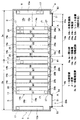
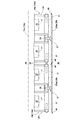
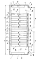
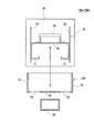
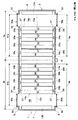
図1,図2に示すように、1は、建屋2内に2台分の移動棚設備3a,3bを設置した収納設備である。上記建屋2は、前後左右の側壁4〜7を有し、さらに側壁4〜7の上部に天井8を有している。上記前側壁4(建屋2の一側部)には左右一対の開口部9a,9bが形成されている。
【0020】
上記一方の移動棚設備3aは、所定間隔をおいて設置された左右一対の固定棚12a,13aと、両固定棚12a,13a間に配置された複数の移動棚14aとで構成されている。各移動棚14aは、両固定棚12a,13a間に形成された移動経路15aに沿って左右方向へ移動自在に構成されている。物品17を所定の移動棚14aや固定棚12a,13aに対して出し入れする場合、各移動棚14aが移動することによって、所定の移動棚14aや固定棚12a,13aの正面に作業用通路16aが形成される。尚、上記一方の開口部9aは上記作業用通路16aと建屋2の前方外部とに連通する。
【0021】
また、上記一方の移動棚設備3aと同様に、他方の移動棚設備3bも、固定棚12b,13bと複数の移動棚14bとで構成されており、各移動棚14bが移動経路15bに沿って左右方向へ移動することによって、所定の移動棚14bや固定棚12b,13bの正面に作業用通路16bが形成される。尚、上記他方の開口部9bは上記作業用通路16bと建屋2の前方外部とに連通する。また、上記両移動棚設備3a,3bは、固定棚13a,13bが隣接した状態で左右一対設けられている。
【0022】
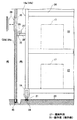
図4に示すように、上記各移動棚14a,14bはそれぞれ、下部フレーム19と、この下部フレーム19上に立設した一対の棚部20と、下部フレーム19に設けられた複数の車輪21と、特定の車輪21を回転駆動させる駆動装置(図示せず)とで構成されている。上記棚部20には、物品17を収納する複数の収納部22が形成されている。また、上記各車輪21が建屋2内の床23に敷設された複数の走行用レール24に支持案内されて転動することにより、各移動棚14a,14bが移動する。尚、図1に示すように、上記各移動棚14a,14bの棚部20をA1〜A8,B1〜B8として区別する。
【0023】
上記各移動棚14aの前側部(一側部)には、一方の開口部9aを開閉する可動扉26aが連結手段27を介して着脱自在に設けられ、同様に、各移動棚14bの前側部には、他方の開口部9bを開閉する可動扉26bが連結手段27を介して着脱自在に設けられている。すなわち、上記各連結手段27は、図4,図5に示すように各移動棚14a,14bの一対の棚部20間に設けられて前方へ突出する四角筒状の取付アーム28と、図13〜図16に示すように上記取付アーム28に対して各可動扉26a,26bの内側に設けられた受け部材29と、上記取付アーム28と受け部材29とを連結する連結具75とで構成されている。
【0024】
図13〜図16に示すように、上記受け部材29は、内側へ向いた下位水平板72と、この下位水平板72の左右両端から起立した補強板73とで構成されている。尚、上記下位水平板72には、上下に貫通した開口部74が左右一対形成されている。また、上記連結具75は、下位水平板72上に載置可能な上位水平板76と、この上位水平板76の左右両端から下向きに垂設された一対の係合板77と、上位水平板76の左右両端から起立した補強板78と、上位水平板76の上面に取付けられた把手79とで構成されている。これによると、図13に示すように、連結具75が受け部材29に取付けられ、取付アーム28の先端部が一対の係合板77間に挿入されることにより、可動扉26aが、連結手段27を介して、移動棚14aに、移動経路15a方向において連結(係合)され、同様に、可動扉26bが、連結手段27を介して、移動棚14bに、移動経路15b方向において連結(係合)される。
【0025】
また、図2,図8に示すように、上記各可動扉26a,26bには、上記受け部材29よりも上方に位置しかつ外側と内側とに開口する操作窓35(操作部の一例)が形成され、さらに、上記操作窓35を閉じる蓋体36がボルト,ナット等を介して着脱自在に設けられている。
【0026】
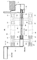
また、各可動扉26a,26bの上部には複数の車輪37が設けられ、建屋2の前側壁4には、上記車輪37を支持する支持レール38が移動経路15a,15bの方向に沿って設けられている。これにより、各可動扉26a,26bは、上記車輪37を介して支持レール38に吊り下げられた構成となり、各可動扉26a,26bの荷重は車輪37を介して支持レール38で支持される。尚、上記車輪37と支持レール38とで支持手段39が構成される。
【0027】
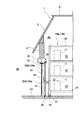
また、図3,図8に示すように、各可動扉26a,26bの下端には案内部材42が設けられ、建屋2の床23には案内レール43が移動経路15a,15bの方向に沿って設けられている。上記案内部材42は案内レール43の凹部44に上方から挿入されており、これによって、各可動扉26a,26bは各移動棚14a,14bの移動方向へ案内され、各可動扉26a,26bが内外方向(前後方向)に揺動するのを防止できる。尚、上記案内部材42と案内レール43とで案内手段45が構成される。
【0028】
また、図6,図7に示すように、各可動扉26a,26bの一側縁には、外側へ寄った外縁部材46が設けられ、この外縁部材46には外シール部材47が設けられている。また、各可動扉26a,26bの他側縁には、内側へ寄った内縁部材48が設けられ、この内縁部材48には内シール部材49が設けられている。上記外シール部材47は隣接する可動扉26a,26bの内縁部材48に外側から接触離間自在であり、同様に、上記内シール部材49は隣接する可動扉26a,26bの外縁部材46に内側から接触離間自在である。
【0029】
また、一方の開口部9aの一端部には、図1に示すように、一方の移動棚設備3aの各移動棚14aがホームポジション(基準位置)まで移動した際に形成される作業用通路16aと建屋2の外部との間を開閉する一方のシャッタ装置50a(開閉手段の一例)が設けられている。同様に、他方の開口部9bの他端部には、他方の移動棚設備3bの各移動棚14bがホームポジション(基準位置)まで移動した際に形成される作業用通路16bと建屋2の外部との間を開閉する他方のシャッタ装置50b(開閉手段の一例)が設けられている。
【0030】
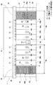
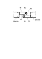
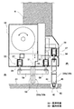
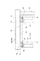
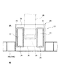
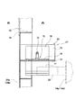
図1,図2に示すように、上記両シャッタ装置50a,50bはそれぞれ、上下方向に開閉自在な上下開閉式のシャッタ本体51と、このシャッタ本体51を上方に巻き取る巻取装置52と、シャッタ本体51の両側部を上下方向(開閉方向)に案内する左右一対の固定および可動ガイドレール53,54(シャッタ案内部材の一例)とで構成されている。図8〜図10に示すように、上記巻取装置52は前側壁4に取付けられており、上記固定ガイドレール53は巻取装置52の一端部側に設けられている。また、巻取装置52の他端部側の上記可動ガイドレール54は、移動手段55を介して、案内位置Aと退避位置Bとの間で移動棚14a,14bの移動方向へ変移可能に構成されている。
【0031】
尚、上記シャッタ本体51は、巻取装置52によって巻き取られることにより両ガイドレール53,54に案内されて上動して開き、巻取装置52から送り出されることにより両ガイドレール53,54に案内されて下動して閉じる。また、可動ガイドレール54は、上記案内位置A(図9の実線参照)においてシャッタ本体51を案内し、退避位置B(図9の仮想線参照)において固定ガイドレール53の隣りに退避する。
【0032】
上記移動手段55は、巻取装置52に設けられた前後一対の支持レール56と、両支持レール56に支持案内されて移動棚14a,14bの移動方向へ転動する複数の支持ローラ57とで構成されており、上記各支持ローラ57は取付部材58を介して可動ガイドレール54の上部に取付けられている。また、図10に示すように、上記支持レール56には、可動ガイドレール54が退避位置Bまで移動したことを検出する検出装置60(リミットスイッチ等)が設けられている。
【0033】
尚、図1に示すように、各可動扉26a,26bとシャッタ本体51および両ガイドレール53,54との配置関係は、上記各可動扉26a,26bが上記シャッタ本体51および両ガイドレール53,54よりも内側に配置されている。また、図9に示すように、可動ガイドレール54と可動扉26a,26bとの間に形成される内外方向(前後方向)の隙間は、可動ガイドレール54に設けられた覆い板63によって閉じられている。
【0034】
図1,図2に示すように、上記建屋2の外側には、各移動棚14a,14bを移動させたりシャッタ本体51を開閉させる集中操作盤61と、この集中操作盤61からの操作によって各移動棚14a,14bの駆動装置やシャッタ装置50a,50bの巻取装置52を制御する制御装置62とが設けられている。尚、上記制御装置62は、検出装置60(図10参照)が可動ガイドレール54を検出した場合、移動棚設備3a,3bの電源をオンに切り換え、検出装置60が可動ガイドレール54を検出しない場合、移動棚設備3a,3bの電源をオフに切り換えるものである。
【0035】
以下、上記構成における作用を説明する。
例えば、一方の移動棚設備3aに対して物品17の出し入れを行う場合、先ず、作業者が集中操作盤61を操作して、一方のシャッタ装置50aのシャッタ本体51を上方へ開く。次に、作業者は、図11に示すように、手動で一方のシャッタ装置50aの可動ガイドレール54を案内位置Aから退避位置Bまで押し引きして移動させる。この際、図8に示すように、可動ガイドレール54は、各支持ローラ57が両支持レール56に支持案内されて転動することによって、円滑に移動する。
【0036】
図11に示すように上記可動ガイドレール54が退避位置Bまで移動すると、図10の仮想線に示すように、検出装置60が可動ガイドレール54を検出し(例えばリミットスイッチがオンになり)、これに基づいて、制御装置62が一方の移動棚設備3aの電源をオンに切り換える。
【0037】
この際、図11に示すように、各移動棚14aはホームポジションから移動していないため、一方の固定棚12aと移動棚14aのA1の棚部20(特定の移動棚)との間に作業用通路16aが形成されており、上記のように一方のシャッタ装置50aが開いたことによって、上記作業用通路16aの前部と建屋2の前方外部との間が開通する。したがって、作業者(またはフォークリフト等の荷役機械)は、建屋2の外部から一方の開口部9aを通って直接に上記作業用通路16a内へ入ることができ、作業用通路16a内において移動棚14aのA1の棚部20または一方の固定棚12aに対し物品17の出し入れを行うことができる。
【0038】
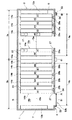
さらに、例えば、A6やA7の棚部20に対して物品17の出し入れを行う場合、作業者が集中操作盤61を操作することにより、図12に示すように、(A1,A2)の移動棚14aと(A3,A4)の移動棚14aと(A5,A6)の移動棚14aとが一方の固定棚12aの側へ移動し、移動棚14aのA6の棚部20とA7の棚部20との間に作業用通路16aが形成される。
【0039】
この際、各移動棚14aの移動に伴って各可動扉26aも移動するため、上記作業用通路16aと建屋2の前方外部との間が開通する。これにより、作業者(またはフォークリフト等の荷役機械)は、建屋2の外部から一方の開口部9aを通って直接に上記作業用通路16a内へ入ることができ、作業用通路16a内において上記A6の棚部20またはA7の棚部20に対し物品17の出し入れを行うことができる。
【0040】
したがって、従来のような出入り用通路を建屋2内に形成する必要はなく、上記出入り用通路が不要になる分だけ、建屋2の設置面積を縮小することができる。
【0041】
また、上記のように各移動棚14aと共に可動扉26aが移動する際、図8に示すように、可動扉26aの案内部材42が案内レール43の凹部44に案内されるため、可動扉26aは、内外方向(前後方向)に揺動することなく、左右方向へ真っ直ぐに移動する。また、この際、図3,図8に示すように、可動扉26aの各車輪37が支持レール38上を転動し、可動扉26aの荷重が各車輪37を介して支持レール38で支持されるため、可動扉26aの荷重が移動棚14aの前部に直接作用して移動棚14aがアンバランスになるといった不具合を防止することができる。
【0042】
上記のようにして物品17の出し入れが完了した後、作業者が集中操作盤61を操作することにより、図11に示すように、各移動棚14aが他方の固定棚13aの側へ移動してホームポジションに戻り、一方の固定棚12aと移動棚14aのA1の棚部20(特定の移動棚)との間に作業用通路16aが形成される。そして、作業者は手動で一方のシャッタ装置50aの可動ガイドレール54を退避位置Bから案内位置Aまで押し引きして移動させる。これにより、図10の実線で示すように、検出装置60が可動ガイドレール54を検出しなくなり(例えばリミットスイッチがオフになり)、これに基づいて、制御装置62が一方の移動棚設備3aの電源をオフに切り換える。
【0043】
さらに、集中操作盤61を操作して、図2に示すように、一方のシャッタ装置50aのシャッタ本体51を下方へ閉じる。これにより、図1に示すように、上記作業用通路16aと建屋2の外部との間が上記シャッタ本体51で閉じられ、以って、一方の開口部9aが各可動扉26aと一方のシャッタ装置50aのシャッタ本体51とで閉じられ、建屋2内の一方の移動棚設備3aは建屋2の外部から遮蔽される。
【0044】
また、同様に各移動棚14aを移動させて、所定の移動棚14aの正面に作業用通路16aを形成することによって、各移動棚14aのA1〜A8の棚部20および固定棚12a,13aに対して物品17を出し入れすることができる。尚、上記のような物品17の出し入れに先立って、図10の仮想線で示すように、一方のシャッタ装置50aの可動ガイドレール54を作業用通路16aから邪魔にならない退避位置Bまで移動させているため、作業者や荷役機械が建屋2の外部から一方の開口部9aを通って作業用通路16a内へ入る際、上記可動ガイドレール54が邪魔になることはない。
【0045】
また、シャッタ本体51が閉まっている状態では、可動ガイドレール54が案内位置Aにあるため、検出装置が上記可動ガイドレール54を検出せず、これに基づいて制御装置62が一方の移動棚設備3aの電源をオフにする。したがって、作業者が不用意に集中操作盤61を操作しても、移動棚14aが移動することはない。これにより、不意に移動棚14aが移動して可動扉26aと案内位置Aの可動ガイドレール54との間に作業者等が挟まれる心配はなく、安全性が確保される。
【0046】
さらに、他方の移動棚設備3bに対して物品17の出し入れを行う場合も同様にして行われる。
また、図6,図7に示すように、互いに隣接する一方の可動扉26aの外シール部材47が他方の可動扉26aの内縁部材48に外側から接触して重複するとともに、他方の可動扉26aの内シール部材49が一方の可動扉26aの外縁部材46に内側から接触して重複するため、隣接する可動扉26a間に隙間が形成されることはない。同様に、隣接する可動扉26b間にも隙間が形成されることもなく、これにより、確実な防爆対策が実施できる。
【0047】
さらに、各移動棚14a,14bが停止した状態で、図5の実線で示すように、蓋体36を可動扉26a,26bから取り外し、作業者が、外部から操作窓35へ手を差し込んで、図14に示すように、連結具75の把手79を持ち、両係合板77を受け部材71の両開口部74の上方へ脱抜することにより、連結具75が受け部材29から取り外され、取付アーム28と受け部材29との連結が解除され、各可動扉26a,26bが各移動棚14a,14bから切り離される。これにより、作業者は各可動扉26a,26bのみを左右方向へ手動で移動させることができる。したがって、点検時や万一の異常発生時、上記のようにして各可動扉26a,26bのみを左右方向へ手動で移動させることによって、移動棚14a,14bを開口部9a,9bに露出させることができるため、移動棚14a,14bの保守点検や修理を容易に行うことができる。
【0048】
保守点検や修理完了後、作業者は、図14に示すように、取付アーム28の上方に受け部材29を位置させた状態で、連結具75の把手79を持ち、図13に示すように、両係合板77を受け部材29の両開口部74へ上方から差し込んで、上位水平板76を下位水平板72上に載置する。これにより、図13,図15,図16に示すように、連結具75が受け部材29に取付けられ、取付アーム28の先端部が両係合板77間に挿入される。これにより、各可動扉26a,26bが、各移動棚14a,14bの取付アーム28に、移動経路15a,15b方向において連結(係合)される。その後、図5の仮想線で示すように、蓋体36を可動扉26a,26bに取り付けて、操作窓35を上記蓋体36で塞ぐ。
【0049】
また、上記第1の実施の形態の連結手段27とは別の構成の連結手段を第2の実施の形態として、以下に説明する。
すなわち、図17に示すように、連結手段81は、各移動棚14a,14bに設けられた取付アーム28と、この取付アーム28に対して各可動扉26a,26bの内側に設けられた受け部材82と、上記取付アーム28と受け部材82とを連結する連結ピン83とで構成されている。
【0050】
上記受け部材82は、縦板部84と、この縦板部84の上下端に設けられた横板部85,86とにより、側面視コ形状に形成されている。上下両横板部85,86にはピン孔87が形成されている。また、上記連結ピン83は、横棒部88と、この横棒部88の両端部から垂下された縦棒部89とで構成されている。
【0051】
そして、上記取付アーム28の先端部を受け部材82の両横板部85,86間に挿入し、上記連結ピン83を上記ピン孔87に差し込むことによって、上記取付アーム28の先端部が連結ピン83の両縦棒部89間に嵌まり込むため、各可動扉26a,26bがそれぞれ、各移動棚14a,14bの取付アーム28に、移動経路15a,15b方向において連結(係合)される。
【0052】
これによると、各移動棚14a,14bが停止した状態で、図5の実線で示すように、蓋体36を可動扉26a,26bから取り外し、作業者が、外部から操作窓35へ手を差し込んで、図17の仮想線で示すように連結ピン83をピン孔87から上方へ脱抜する。これにより、取付アーム28と受け部材82との連結が解除されるため、各可動扉26a,26bは各移動棚14a,14bから切り離され、作業者は各可動扉26a,26bのみを左右方向へ手動で移動させることができる。したがって、点検時や万一の異常発生時、上記のようにして各可動扉26a,26bのみを左右方向へ手動で移動させることによって、移動棚14a,14bを開口部9a,9bに露出させることができるため、移動棚14a,14bの保守点検や修理を容易に行うことができる。
【0053】
保守点検や修理完了後、作業者は、図17の実線で示すように、取付アーム28の先端を受け部材29の両横板部85,86間に挿入し、連結ピン83をピン孔87に差し込む。これにより、可動扉26a,26bが移動棚14a,14bに連結される。その後、図5の仮想線で示すように、蓋体36を可動扉26a,26bに取り付けて、操作窓35を上記蓋体36で塞ぐ。
【0054】
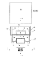
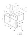
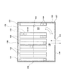
上記各実施の形態では、建屋2の前側壁4に開口部9a,9bを形成し、各移動棚14a,14bの前側部にそれぞれ可動扉26a,26bを設け、さらに、前側壁4(開口部9a,9b)にシャッタ装置50a,50bを設けているが、第3の実施の形態として、図18に示すように、さらに、建屋2の後側壁5にも開口部91a,91bを形成し、可動扉26a,26bを各移動棚14a,14bの後側部にも設け、シャッタ装置50a,50bを後側壁5にも設けてもよい。
【0055】
上記各実施の形態では、図1,図18に示すように、建屋2内に2台分の移動棚設備3a,3bを並べて設置しているが、1台分または3台分以上設置してもよい。この際、シャッタ装置50a,50bの数は移動棚設備3a,3bの台数と同数だけ設ければよい。
【0056】
上記各実施の形態では、各移動棚設備3a,3bにそれぞれ固定棚12a,12b,13a,13bを設けているが、これら固定棚12a,12b,13a,13bを設けなくてもよい。
【0057】
上記各実施の形態では、各移動棚設備3a,3bにそれぞれ移動棚14a,14bを4台ずつ設けているが、4台以外の複数台であってもよい。
上記各実施の形態では、シャッタ本体51を上下方向に開閉しているが、左右方向に開閉してもよい。
【0058】
上記各実施の形態では、各シャッタ装置50a,50bの可動ガイドレール54を手動で押し引きして移動させているが、モータ等の駆動装置を用いて自動的に移動させてもよい。
【0059】
上記各実施の形態では、各連結手段27,81を介して各可動扉26a,26bを各移動棚14a,14bに連結しているが、上記連結手段27,81を無くして各可動扉26a,26bを直接に各移動棚14a,14bに取り付けてもよい。また、操作窓35を無くしてもよい。
【0060】
上記各実施の形態では、図5に示すように、操作窓35を閉じる蓋体36がボルト,ナット等を介して着脱自在に設けられているが、ヒンジ等を介して上記蓋体36を可動扉26a,26bに取付け、蓋体36で上記操作窓35を開閉する開閉扉形式であってもよい。
【0061】
上記各実施の形態では、防爆仕様の収納設備1を挙げたが、防爆仕様に限定されるものではない。
【0062】
【発明の効果】
以上のように本第1発明によると、従来のような出入り用通路を建屋内に形成する必要はなく、上記出入り用通路が不要になる分だけ、建屋の設置面積を縮小することができる。また、所定の移動棚に対して物品の出し入れを行う場合、シャッタ装置を上方(または下方)に開き、移動棚を移動させて、所定の移動棚の前方に作業用通路を形成する。また、物品の出し入れが完了した後、特定の移動棚の前方に作業用通路を形成し、この状態でシャッタ装置を下方(または上方)に閉じる。
【0063】
本第2発明によると、シャッタ案内部材を移動棚の移動方向へ変移させて作業用通路から邪魔にならない位置へ退避させることができ、これにより、建屋の外部から開口部を通って作業用通路内へ入る際、上記シャッタ案内部材が邪魔になることはない。
【0064】
本第3発明によると、可動扉は、案内手段によって案内されながら移動するため、移動棚の移動方向に沿って確実に移動する。また、可動扉の荷重が支持手段によって建屋側で支持されるため、可動扉の荷重が移動棚に直接作用して移動棚がアンバランスになるといった不具合を防止することができる。
【0065】
本第4発明によると、互いに隣接する可動扉間に隙間が形成されることはない。
【0066】
本第5発明によると、点検時や万一の異常発生時、作業者は、可動扉の外部から操作部を通して連結手段を操作し、可動扉を移動棚から取り外すことができる。これにより、移動棚の保守点検や修理を容易に行うことができる。
【0067】
本第8発明によると、物品の出し入れが完了した後、各移動棚を基準位置まで移動させ、さらに開閉手段を閉じることによって、作業用通路と建屋の外部との間が開閉手段で閉じられる。以って、開口部は各可動扉と開閉手段とで閉じられ、建屋内の移動棚設備は建屋の外部から遮断される。
【図面の簡単な説明】
【図1】本発明の第1の実施の形態における収納設備の天井を除いた平面図である。
【図2】同、収納設備の正面図である。
【図3】同、収納設備の開口部の側面図である。
【図4】同、収納設備の移動棚の正面図である。
【図5】同、収納設備の移動棚と可動扉との連結部分の側面図である。
【図6】同、収納設備の移動棚の前部の平面図であり、一対の可動扉同士が隣接している状態を示す。
【図7】同、収納設備の隣接した可動扉同士の重複部分の拡大平面図である。
【図8】同、収納設備のシャッタ装置および可動扉の側面図である。
【図9】同、収納設備のシャッタ装置の横断面図である。
【図10】同、収納設備のシャッタ装置のガイドレールの上部の正面図である。
【図11】同、収納設備の天井を除いた平面図であり、可動ガイドレールを退避位置まで移動させた状態を示す。
【図12】同、収納設備の天井を除いた平面図であり、可動ガイドレールを退避位置まで移動させ、各移動棚をホームポジションから移動させて、A6の棚部とA7の棚部との間に作業用通路を形成した状態を示す。
【図13】同、収納設備の移動棚と可動扉との連結手段の図であり、移動棚側から可動扉側へ向かって見た図である。
【図14】図13において、連結手段の連結具を受け部材から上方へ取り外した状態を示す図である。
【図15】図13におけるX−X矢視図である。
【図16】図13におけるY−Y矢視図である。
【図17】本発明の第2の実施の形態における収納設備の移動棚と可動扉との連結手段の斜視図である。
【図18】本発明の第3の実施の形態における収納設備の天井を除いた平面図である。
【図19】従来の収納設備の天井を除いた平面図である。
【符号の説明】
1 収納設備
2 建屋
3a,3b 移動棚設備
9a,9b 開口部
14a,14b 移動棚
15a,15b 移動経路
16a,16b 作業用通路
26a,26b 可動扉
27 連結手段
35 操作窓(操作部)
39 支持手段
45 案内手段
50a,50b シャッタ装置(開閉手段)
51 シャッタ本体
54 可動ガイドレール(シャッタ案内部材)
81 連結手段
91a,91b 開口部[0001]
BACKGROUND OF THE INVENTION
The present invention relates to a storage facility in which a moving shelf facility is installed in a building.
[0002]
[Prior art]
Conventionally, as shown in FIG. 19, the moving shelf equipment is composed of a pair of left and right fixed
[0003]
When handling dangerous materials (for example, combustible materials) as the
[0004]
[Problems to be solved by the invention]
However, in the above-described conventional format, since the entrance /
[0005]
An object of this invention is to provide the storage equipment which can reduce the installation area of the building in which the movement shelf installation is provided.
[0006]
[Means for Solving the Problems]
In order to achieve the above object, the first invention is a storage facility in which a moving shelf facility is installed in a building,
The moving shelf equipment has a moving shelf that is movable along a moving path, and is configured such that a working path is formed in front of a predetermined moving shelf by movement of the moving shelf,
At least one side of the building is formed with an opening communicating with the outside of the building and the work passage,
A movable door that opens and closes the opening is provided on at least one side of the movable shelf,
The opening is provided with opening / closing means for opening / closing between the working passage and the outside of the building.,
As the opening / closing means, a vertical opening / closing shutter device is provided.Is.
[0007]
According to this, when taking in and out goods to a predetermined moving shelf,Shutter deviceTheUpward (or downward)The movable shelf is opened and a working path is formed in front of the predetermined movable shelf. At this time, since the movable door moves with the movement of the movable shelf, the work passage and the outside of the building are opened. As a result, it is possible to enter the work path directly from the outside of the building through the opening, and the articles are taken in and out of the predetermined movable shelf in the work path. Therefore, it is not necessary to form a conventional entrance / exit passage in the building, and the installation area of the building can be reduced by an amount corresponding to the need for the entrance / exit passage.
[0008]
In addition, after the loading and unloading of articles is completed, a work passage is formed in front of a specific moving shelf, and in this stateShutter deviceTheDown (or up)close. As a result, the gap between the work passage and the outside of the buildingShutter deviceSo that the opening is a movable door.Shutter deviceThe mobile shelf equipment in the building is shut off from the outside of the building.
[0009]
This second inventionA storage facility with moving shelf equipment installed in the building,
The moving shelf equipment has a moving shelf that is movable along a moving path, and is configured such that a working path is formed in front of a predetermined moving shelf by movement of the moving shelf,
At least one side of the building is formed with an opening communicating with the outside of the building and the work passage,
A movable door that opens and closes the opening is provided on at least one side of the movable shelf,
Opening and closing means for opening and closing between the work passage and the outside of the building is provided in the opening,
A shutter device is provided as the opening / closing means,
The shutter device includes a shutter body that can be freely opened and closed, and a shutter guide member that guides the shutter body in the opening and closing direction.
The position of the shutter guide member is configured to be movable in the moving direction of the movable shelf.Is.
[0010]
according to this,When an article is taken in and out of a predetermined moving shelf, the shutter guide member can be moved in the moving direction of the moving shelf after the shutter body is opened, and can be retracted from the working path to an unobstructed position. Thereby, when entering the work passage from the outside of the building through the opening, the shutter guide member does not get in the way.
[0011]
This third inventionA storage facility with moving shelf equipment installed in the building,
The moving shelf equipment has a moving shelf that is movable along a moving path, and is configured such that a working path is formed in front of a predetermined moving shelf by movement of the moving shelf,
At least one side of the building is formed with an opening communicating with the outside of the building and the work passage,
A movable door that opens and closes the opening is provided on at least one side of the movable shelf,
Guide means for guiding the movable door in the moving direction of the movable shelf, and support means for supporting the movable door itself on the building side are provided,
Opening and closing means for opening and closing between the working passage and the outside of the building is provided in the opening.Is.
according to this,When the movable door moves together with the moving shelf, the movable door moves while being guided by the guide means, and thus moves reliably along the moving direction of the moving shelf. Further, since the load of the movable door is supported on the building side by the support means, it is possible to prevent a problem that the load of the movable door directly acts on the movable shelf and the movable shelf becomes unbalanced.
[0012]
The fourth invention isA storage facility with moving shelf equipment installed in the building,
The moving shelf equipment has a moving shelf that is movable along a moving path, and is configured such that a working path is formed in front of a predetermined moving shelf by movement of the moving shelf,
At least one side of the building is formed with an opening communicating with the outside of the building and the work passage,
A movable door that opens and closes the opening is provided on at least one side of the movable shelf,
Among the adjacent movable doors, one side end of one movable door overlaps with the other side end of the other movable door,
Opening and closing means for opening and closing between the working passage and the outside of the building is provided in the opening.Is.
[0013]
according to this,There is no gap formed between the movable doors adjacent to each other.
[0014]
The fifth inventionA storage facility with moving shelf equipment installed in the building,
The moving shelf equipment has a moving shelf that is movable along a moving path, and is configured such that a working path is formed in front of a predetermined moving shelf by movement of the moving shelf,
At least one side of the building is formed with an opening communicating with the outside of the building and the work passage,
A movable door that opens and closes the opening is provided on at least one side of the movable shelf,
The movable door is detachably attached to the movable shelf via the connecting means,
In the movable door, an operation part for operating the connecting means from outside to attach and remove the movable door to the moving shelf is formed,
Opening and closing means for opening and closing between the working passage and the outside of the building is provided in the opening.Is.
according to this,At the time of inspection or in the event of an abnormality, the operator can operate the connecting means from the outside of the movable door through the operation unit to remove the movable door from the movable shelf. Thereby, the maintenance check and repair of a movable shelf can be performed easily.
[0015]
This sixth inventionA storage facility with moving shelf equipment installed in the building,
The moving shelf equipment has a moving shelf that is movable along a moving path, and is configured such that a working path is formed in front of a predetermined moving shelf by movement of the moving shelf,
At least one side of the building is formed with an opening communicating with the outside of the building and the work passage,
A movable door that opens and closes the opening is provided on at least one side of the movable shelf,
Opening and closing means for opening and closing between the work passage and the outside of the building is provided in the opening,
The movable door is disposed inside the opening / closing means.
[0016]
This seventh inventionA storage facility with moving shelf equipment installed in the building,
The moving shelf equipment has a moving shelf that is movable along a moving path, and is configured such that a working path is formed in front of a predetermined moving shelf by movement of the moving shelf,
At least one side of the building is formed with an opening communicating with the outside of the building and the work passage,
A movable door that opens and closes the opening is provided on at least one side of the movable shelf,
Opening and closing means for opening and closing between the work passage and the outside of the building is provided in the opening,
The opening / closing means is configured to be operable in a state where the power of the moving shelf facility is turned off.Is.
[0017]
The eighth invention is provided with a plurality of movable shelves that are movable along the movement path,
Each of these moving shelves has a movable door,
The opening / closing means opens and closes between the work passage formed when each movable shelf moves to the reference position and the outside of the building.
[0018]
According to this, after completion of the taking in / out of the article, the movable shelf is moved to the reference position, and the opening / closing means is closed, so that the gap between the work passage and the outside of the building is closed by the opening / closing means. Accordingly, the opening is closed by each movable door and the opening / closing means, and the movable shelf equipment in the building is blocked from the outside of the building.
[0019]
DETAILED DESCRIPTION OF THE INVENTION
A first embodiment of the present invention will be described below with reference to FIGS.
As shown in FIGS. 1 and 2,
[0020]
The one moving
[0021]
Similarly to the one moving
[0022]
As shown in FIG. 4, each of the
[0023]
On the front side (one side) of each
[0024]
As shown in FIGS. 13 to 16, the receiving
[0025]
As shown in FIGS. 2 and 8, each of the
[0026]
A plurality of
[0027]
3 and 8, a
[0028]
Further, as shown in FIGS. 6 and 7, an
[0029]
Further, at one end of one
[0030]
As shown in FIGS. 1 and 2, each of the
[0031]
Note that the
[0032]
The moving means 55 includes a pair of front and rear support rails 56 provided in the winding
[0033]
As shown in FIG. 1, the
[0034]
As shown in FIGS. 1 and 2, on the outside of the
[0035]
Hereinafter, the operation of the above configuration will be described.
For example, when the
[0036]
When the
[0037]
At this time, as shown in FIG. 11, since each
[0038]
Furthermore, for example, when the
[0039]
At this time, each
[0040]
Therefore, it is not necessary to form the entrance / exit passage in the
[0041]
Further, when the
[0042]
After the loading and unloading of the
[0043]
Further, the
[0044]
Similarly, by moving each
[0045]
In the state where the shutter
[0046]
Further, the same operation is performed when the
As shown in FIGS. 6 and 7, the
[0047]
Further, with the
[0048]
After completion of the maintenance inspection and repair, the operator holds the
[0049]
Further, a connecting means having a configuration different from the connecting means 27 of the first embodiment will be described below as a second embodiment.
That is, as shown in FIG. 17, the connecting
[0050]
The receiving
[0051]
Then, the distal end portion of the mounting
[0052]
According to this, with the
[0053]
After completion of the maintenance inspection and repair, the operator inserts the tip of the mounting
[0054]
In each of the above embodiments, the
[0055]
In each of the above embodiments, as shown in FIGS. 1 and 18, two moving
[0056]
In each said embodiment, although each fixed
[0057]
In each of the above embodiments, four moving
In each of the above embodiments, the shutter
[0058]
In each of the above embodiments, the
[0059]
In each of the above embodiments, the
[0060]
In each of the embodiments described above, as shown in FIG. 5, the
[0061]
In each of the above-described embodiments, the explosion-proof
[0062]
【The invention's effect】
As described above, according to the first aspect of the present invention, it is not necessary to form a conventional entrance / exit passage in the building, and the installation area of the building can be reduced by the amount that the entrance / exit passage is unnecessary.Further, when an article is taken in and out of a predetermined movable shelf, the shutter device is opened upward (or downward), the movable shelf is moved, and a working path is formed in front of the predetermined movable shelf. In addition, after the loading / unloading of the article is completed, a work path is formed in front of a specific movable shelf, and the shutter device is closed downward (or upward) in this state.
[0063]
According to the second invention,The shutter guide member can be displaced in the moving direction of the moving shelf and retracted from the work path to an unobstructed position, so that when the shutter enters the work path from the outside of the building through the opening, the shutter The guide member does not get in the way.
[0064]
According to the third invention,Since the movable door moves while being guided by the guide means, it moves reliably along the moving direction of the moving shelf. Further, since the load of the movable door is supported on the building side by the support means, it is possible to prevent a problem that the load of the movable door directly acts on the movable shelf and the movable shelf becomes unbalanced.
[0065]
According to the fourth invention,There is no gap formed between the movable doors adjacent to each other.
[0066]
According to the fifth invention,At the time of inspection or in the event of an abnormality, the operator can operate the connecting means from the outside of the movable door through the operation unit to remove the movable door from the movable shelf. Thereby, the maintenance check and repair of a movable shelf can be performed easily.
[0067]
According to the eighth aspect of the present invention, after the loading / unloading of the article is completed, each movable shelf is moved to the reference position, and the opening / closing means is closed to close the space between the work passage and the outside of the building by the opening / closing means. Accordingly, the opening is closed by each movable door and the opening / closing means, and the movable shelf equipment in the building is blocked from the outside of the building.
[Brief description of the drawings]
FIG. 1 is a plan view of a storage facility according to a first embodiment of the present invention excluding a ceiling.
FIG. 2 is a front view of the storage facility.
FIG. 3 is a side view of the opening of the storage facility.
FIG. 4 is a front view of the movable shelf of the storage facility.
FIG. 5 is a side view of a connecting portion between the movable shelf of the storage facility and the movable door.
FIG. 6 is a plan view of the front part of the moving shelf of the storage facility, showing a state in which a pair of movable doors are adjacent to each other.
FIG. 7 is an enlarged plan view of an overlapping portion between adjacent movable doors of the storage facility.
FIG. 8 is a side view of the shutter device and the movable door of the storage facility.
FIG. 9 is a cross-sectional view of the shutter device of the storage facility.
FIG. 10 is a front view of the upper part of the guide rail of the shutter device of the storage facility.
FIG. 11 is a plan view of the storage facility with the ceiling removed, showing a state in which the movable guide rail is moved to the retracted position.
FIG. 12 is a plan view of the storage facility with the ceiling removed, and the movable guide rail is moved to the retracted position, and each movable shelf is moved from the home position so that the A6 shelf and the A7 shelf are The state which formed the channel | path for work between is shown.
FIG. 13 is a view of the connecting means between the movable shelf and the movable door of the storage facility, as viewed from the movable shelf side toward the movable door side.
FIG. 14 is a view showing a state where the coupling tool of the coupling means is removed upward from the receiving member in FIG. 13;
15 is a view taken along arrow XX in FIG.
16 is a view on arrow YY in FIG. 13;
FIG. 17 is a perspective view of a connecting means for connecting the movable shelf and the movable door of the storage facility according to the second embodiment of the present invention.
FIG. 18 is a plan view of the storage facility according to the third embodiment of the present invention excluding the ceiling.
FIG. 19 is a plan view of the conventional storage facility with the ceiling removed.
[Explanation of symbols]
1 Storage equipment
2 building
3a, 3b Moving shelf equipment
9a, 9b opening
14a, 14b Moving shelf
15a, 15b travel route
16a, 16b Work passage
26a, 26b movable door
27 Connecting means
35 Operation window (operation unit)
39 Support means
45 Guide means
50a, 50b Shutter device (opening / closing means)
51 Shutter body
54 Movable guide rail (shutter guide member)
81 Connecting means
91a, 91b opening
Claims (8)
上記移動棚設備は、移動経路に沿って移動自在な移動棚を有し、かつ、移動棚の移動によって所定の移動棚の前方に作業用通路が形成されるように構成され、
上記建屋の少なくとも一側部に、建屋の外部と上記作業用通路とに連通する開口部が形成され、
上記移動棚の少なくとも一側部に、上記開口部を開閉する可動扉が設けられ、
上記開口部に、上記作業用通路と建屋の外部との間を開閉する開閉手段が設けられ、
上記開閉手段として上下開閉式のシャッタ装置が設けられていることを特徴とする収納設備。A storage facility with moving shelf equipment installed in the building,
The moving shelf equipment has a moving shelf that is movable along a moving path, and is configured such that a working path is formed in front of a predetermined moving shelf by movement of the moving shelf,
At least one side of the building is formed with an opening communicating with the outside of the building and the work passage,
A movable door that opens and closes the opening is provided on at least one side of the movable shelf,
Opening and closing means for opening and closing between the work passage and the outside of the building is provided in the opening ,
A storage facility characterized in that an open / close shutter device is provided as the opening / closing means .
上記移動棚設備は、移動経路に沿って移動自在な移動棚を有し、かつ、移動棚の移動によって所定の移動棚の前方に作業用通路が形成されるように構成され、
上記建屋の少なくとも一側部に、建屋の外部と上記作業用通路とに連通する開口部が形成され、
上記移動棚の少なくとも一側部に、上記開口部を開閉する可動扉が設けられ、
上記開口部に、上記作業用通路と建屋の外部との間を開閉する開閉手段が設けられ、
上記開閉手段としてシャッタ装置が設けられ、
上記シャッタ装置は、開閉自在なシャッタ本体と、このシャッタ本体を開閉方向に案内するシャッタ案内部材とで構成され、
上記シャッタ案内部材の位置が移動棚の移動方向へ変移可能に構成されていることを特徴とする収納設備。 A storage facility with moving shelf equipment installed in the building,
The moving shelf equipment has a moving shelf that is movable along a moving path, and is configured such that a working path is formed in front of a predetermined moving shelf by movement of the moving shelf,
At least one side of the building is formed with an opening communicating with the outside of the building and the work passage,
A movable door that opens and closes the opening is provided on at least one side of the movable shelf,
Opening and closing means for opening and closing between the work passage and the outside of the building is provided in the opening,
A shutter device is provided as the opening / closing means,
The shutter device includes a shutter body that can be freely opened and closed, and a shutter guide member that guides the shutter body in the opening and closing direction.
A storage facility characterized in that the position of the shutter guide member can be shifted in the moving direction of the movable shelf .
上記移動棚設備は、移動経路に沿って移動自在な移動棚を有し、かつ、移動棚の移動によって所定の移動棚の前方に作業用通路が形成されるように構成され、
上記建屋の少なくとも一側部に、建屋の外部と上記作業用通路とに連通する開口部が形成され、
上記移動棚の少なくとも一側部に、上記開口部を開閉する可動扉が設けられ、
上記可動扉を移動棚の移動方向へ案内する案内手段と、可動扉自体を建屋側で支持する支持手段とが設けられ、
上記開口部に、上記作業用通路と建屋の外部との間を開閉する開閉手段が設けられていることを特徴とする収納設備。 A storage facility with moving shelf equipment installed in the building,
The moving shelf equipment has a moving shelf that is movable along a moving path, and is configured such that a working path is formed in front of a predetermined moving shelf by movement of the moving shelf,
At least one side of the building is formed with an opening communicating with the outside of the building and the work passage,
A movable door that opens and closes the opening is provided on at least one side of the movable shelf,
Guide means for guiding the movable door in the moving direction of the movable shelf, and support means for supporting the movable door itself on the building side are provided,
Opening and closing means for opening and closing between the working passage and the outside of the building is provided in the opening .
上記移動棚設備は、移動経路に沿って移動自在な移動棚を有し、かつ、移動棚の移動によって所定の移動棚の前方に作業用通路が形成されるように構成され、
上記建屋の少なくとも一側部に、建屋の外部と上記作業用通路とに連通する開口部が形成され、
上記移動棚の少なくとも一側部に、上記開口部を開閉する可動扉が設けられ、
隣接する上記可動扉のうち、一方の可動扉の一側端と他方の可動扉の他側端とが重複し、
上記開口部に、上記作業用通路と建屋の外部との間を開閉する開閉手段が設けられていることを特徴とする収納設備。 A storage facility with moving shelf equipment installed in the building,
The moving shelf equipment has a moving shelf that is movable along a moving path, and is configured such that a working path is formed in front of a predetermined moving shelf by movement of the moving shelf,
At least one side of the building is formed with an opening communicating with the outside of the building and the work passage,
A movable door that opens and closes the opening is provided on at least one side of the movable shelf,
Among the adjacent movable doors, one side end of one movable door overlaps with the other side end of the other movable door,
Opening and closing means for opening and closing between the working passage and the outside of the building is provided in the opening .
上記移動棚設備は、移動経路に沿って移動自在な移動棚を有し、かつ、移動棚の移動によって所定の移動棚の前方に作業用通路が形成されるように構成され、
上記建屋の少なくとも一側部に、建屋の外部と上記作業用通路とに連通する開口部が形成され、
上記移動棚の少なくとも一側部に、上記開口部を開閉する可動扉が設けられ、
上記可動扉は、連結手段を介して、移動棚に着脱自在に取付けられ、
上記可動扉に、外部から上記連結手段を操作して可動扉を移動棚に取付け取外しするための操作部が形成され、
上記開口部に、上記作業用通路と建屋の外部との間を開閉する開閉手段が設けられていることを特徴とする収納設備。 A storage facility with moving shelf equipment installed in the building,
The moving shelf equipment has a moving shelf that is movable along a moving path, and is configured such that a working path is formed in front of a predetermined moving shelf by movement of the moving shelf,
At least one side of the building is formed with an opening communicating with the outside of the building and the work passage,
A movable door that opens and closes the opening is provided on at least one side of the movable shelf,
The movable door is detachably attached to the movable shelf via the connecting means,
In the movable door, an operation part for operating the connecting means from outside to attach and remove the movable door to the moving shelf is formed,
Opening and closing means for opening and closing between the working passage and the outside of the building is provided in the opening .
上記移動棚設備は、移動経路に沿って移動自在な移動棚を有し、かつ、移動棚の移動によって所定の移動棚の前方に作業用通路が形成されるように構成され、
上記建屋の少なくとも一側部に、建屋の外部と上記作業用通路とに連通する開口部が形成され、
上記移動棚の少なくとも一側部に、上記開口部を開閉する可動扉が設けられ、
上記開口部に、上記作業用通路と建屋の外部との間を開閉する開閉手段が設けられ、
上記可動扉は開閉手段よりも内側に配置されていることを特徴とする収納設備。 A storage facility with moving shelf equipment installed in the building,
The moving shelf equipment has a moving shelf that is movable along a moving path, and is configured such that a working path is formed in front of a predetermined moving shelf by movement of the moving shelf,
At least one side of the building is formed with an opening communicating with the outside of the building and the work passage,
A movable door that opens and closes the opening is provided on at least one side of the movable shelf,
Opening and closing means for opening and closing between the work passage and the outside of the building is provided in the opening,
A storage facility characterized in that the movable door is arranged inside the opening / closing means .
上記移動棚設備は、移動経路に沿って移動自在な移動棚を有し、かつ、移動棚の移動によって所定の移動棚の前方に作業用通路が形成されるように構成され、
上記建屋の少なくとも一側部に、建屋の外部と上記作業用通路とに連通する開口部が形成され、
上記移動棚の少なくとも一側部に、上記開口部を開閉する可動扉が設けられ、
上記開口部に、上記作業用通路と建屋の外部との間を開閉する開閉手段が設けられ、
上記移動棚設備の電源が切れた状態で、開閉手段が作動可能に構成されていることを特徴とする収納設備。 A storage facility with moving shelf equipment installed in the building,
The moving shelf equipment has a moving shelf that is movable along a moving path, and is configured such that a working path is formed in front of a predetermined moving shelf by movement of the moving shelf,
At least one side of the building is formed with an opening communicating with the outside of the building and the work passage,
A movable door that opens and closes the opening is provided on at least one side of the movable shelf,
Opening and closing means for opening and closing between the work passage and the outside of the building is provided in the opening,
A storage facility characterized in that the opening / closing means is operable in a state where the power of the moving shelf facility is turned off .
これら各移動棚に可動扉が設けられ、Each of these mobile shelves has a movable door,
開閉手段は、各移動棚が基準位置まで移動した際に形成される作業用通路と建屋の外部との間を開閉することを特徴とする請求項1から請求項7のいずれか1項に記載の収納設備。The opening / closing means opens and closes between a work passage formed when each movable shelf moves to a reference position and the outside of the building. Storage facilities.
Priority Applications (1)
| Application Number | Priority Date | Filing Date | Title |
|---|---|---|---|
| JP2000350337A JP3772664B2 (en) | 2000-11-17 | 2000-11-17 | Storage equipment |
Applications Claiming Priority (1)
| Application Number | Priority Date | Filing Date | Title |
|---|---|---|---|
| JP2000350337A JP3772664B2 (en) | 2000-11-17 | 2000-11-17 | Storage equipment |
Publications (2)
| Publication Number | Publication Date |
|---|---|
| JP2002154611A JP2002154611A (en) | 2002-05-28 |
| JP3772664B2 true JP3772664B2 (en) | 2006-05-10 |
Family
ID=18823582
Family Applications (1)
| Application Number | Title | Priority Date | Filing Date |
|---|---|---|---|
| JP2000350337A Expired - Fee Related JP3772664B2 (en) | 2000-11-17 | 2000-11-17 | Storage equipment |
Country Status (1)
| Country | Link |
|---|---|
| JP (1) | JP3772664B2 (en) |
Cited By (1)
| Publication number | Priority date | Publication date | Assignee | Title |
|---|---|---|---|---|
| KR102065995B1 (en) * | 2019-07-24 | 2020-01-14 | 주식회사 노바하이텍 | Hybrid high efficiency agricultural and marine products dryer |
Families Citing this family (2)
| Publication number | Priority date | Publication date | Assignee | Title |
|---|---|---|---|---|
| JP2007022677A (en) * | 2005-07-12 | 2007-02-01 | Asyst Shinko Inc | Stocker device |
| JP7663281B1 (en) * | 2024-10-30 | 2025-04-16 | Agriit株式会社 | Rack system, control device and control method |
-
2000
- 2000-11-17 JP JP2000350337A patent/JP3772664B2/en not_active Expired - Fee Related
Cited By (1)
| Publication number | Priority date | Publication date | Assignee | Title |
|---|---|---|---|---|
| KR102065995B1 (en) * | 2019-07-24 | 2020-01-14 | 주식회사 노바하이텍 | Hybrid high efficiency agricultural and marine products dryer |
Also Published As
| Publication number | Publication date |
|---|---|
| JP2002154611A (en) | 2002-05-28 |
Similar Documents
| Publication | Publication Date | Title |
|---|---|---|
| JP7568514B2 (en) | A containment grid with a container access station equipped with a locking device for locking a remotely operated vehicle | |
| CN102482040A (en) | Improved palletizing equipment combined with secure access | |
| JP2010540373A (en) | Safe pallet loading equipment | |
| TWI441765B (en) | Warehouse equipment | |
| JP3772664B2 (en) | Storage equipment | |
| TWI836071B (en) | repository system | |
| JPH0567527B2 (en) | ||
| JP2001171806A (en) | Transfer equipment station | |
| JP5738611B2 (en) | Vertical transfer device | |
| JP2019203361A (en) | Mechanical parking device | |
| JP2023018168A (en) | elevator | |
| JP5141563B2 (en) | Automatic operation equipment door device | |
| JP3868328B2 (en) | Underground parking system | |
| JPH11193109A (en) | Automatic warehouse system | |
| JP5469431B2 (en) | Mechanical parking equipment and its vehicle entry / exit method | |
| JP2532258Y2 (en) | Automatic warehouse | |
| JPH04292307A (en) | Warehouse facilities | |
| JP3832374B2 (en) | Automatic warehouse | |
| NO20221405A1 (en) | A service vehicle and a method for retrieving a malfunctioning container handling vehicle | |
| JPH022864Y2 (en) | ||
| JP2003172065A (en) | Large door equipment | |
| JPH074410U (en) | Automatic warehouse | |
| JPH0682008U (en) | Stacker crane safety fence | |
| JPH09132968A (en) | Multi-level parking device | |
| WO2026074856A1 (en) | Stocker |
Legal Events
| Date | Code | Title | Description |
|---|---|---|---|
| A621 | Written request for application examination |
Free format text: JAPANESE INTERMEDIATE CODE: A621 Effective date: 20031216 |
|
| A977 | Report on retrieval |
Free format text: JAPANESE INTERMEDIATE CODE: A971007 Effective date: 20050921 |
|
| A131 | Notification of reasons for refusal |
Free format text: JAPANESE INTERMEDIATE CODE: A131 Effective date: 20051018 |
|
| A521 | Written amendment |
Free format text: JAPANESE INTERMEDIATE CODE: A523 Effective date: 20051206 |
|
| TRDD | Decision of grant or rejection written | ||
| A01 | Written decision to grant a patent or to grant a registration (utility model) |
Free format text: JAPANESE INTERMEDIATE CODE: A01 Effective date: 20060124 |
|
| A61 | First payment of annual fees (during grant procedure) |
Free format text: JAPANESE INTERMEDIATE CODE: A61 Effective date: 20060206 |
|
| R150 | Certificate of patent or registration of utility model |
Ref document number: 3772664 Country of ref document: JP Free format text: JAPANESE INTERMEDIATE CODE: R150 Free format text: JAPANESE INTERMEDIATE CODE: R150 |
|
| FPAY | Renewal fee payment (event date is renewal date of database) |
Free format text: PAYMENT UNTIL: 20100224 Year of fee payment: 4 |
|
| FPAY | Renewal fee payment (event date is renewal date of database) |
Free format text: PAYMENT UNTIL: 20110224 Year of fee payment: 5 |
|
| FPAY | Renewal fee payment (event date is renewal date of database) |
Free format text: PAYMENT UNTIL: 20110224 Year of fee payment: 5 |
|
| FPAY | Renewal fee payment (event date is renewal date of database) |
Free format text: PAYMENT UNTIL: 20110224 Year of fee payment: 5 |
|
| FPAY | Renewal fee payment (event date is renewal date of database) |
Free format text: PAYMENT UNTIL: 20120224 Year of fee payment: 6 |
|
| R250 | Receipt of annual fees |
Free format text: JAPANESE INTERMEDIATE CODE: R250 |
|
| FPAY | Renewal fee payment (event date is renewal date of database) |
Free format text: PAYMENT UNTIL: 20120224 Year of fee payment: 6 |
|
| FPAY | Renewal fee payment (event date is renewal date of database) |
Free format text: PAYMENT UNTIL: 20130224 Year of fee payment: 7 |
|
| R250 | Receipt of annual fees |
Free format text: JAPANESE INTERMEDIATE CODE: R250 |
|
| FPAY | Renewal fee payment (event date is renewal date of database) |
Free format text: PAYMENT UNTIL: 20130224 Year of fee payment: 7 |
|
| FPAY | Renewal fee payment (event date is renewal date of database) |
Free format text: PAYMENT UNTIL: 20140224 Year of fee payment: 8 |
|
| R250 | Receipt of annual fees |
Free format text: JAPANESE INTERMEDIATE CODE: R250 |
|
| R250 | Receipt of annual fees |
Free format text: JAPANESE INTERMEDIATE CODE: R250 |
|
| R250 | Receipt of annual fees |
Free format text: JAPANESE INTERMEDIATE CODE: R250 |
|
| R250 | Receipt of annual fees |
Free format text: JAPANESE INTERMEDIATE CODE: R250 |
|
| R250 | Receipt of annual fees |
Free format text: JAPANESE INTERMEDIATE CODE: R250 |
|
| R250 | Receipt of annual fees |
Free format text: JAPANESE INTERMEDIATE CODE: R250 |
|
| R250 | Receipt of annual fees |
Free format text: JAPANESE INTERMEDIATE CODE: R250 |
|
| LAPS | Cancellation because of no payment of annual fees |