JP3772655B2 - air purifier - Google Patents
air purifier Download PDFInfo
- Publication number
- JP3772655B2 JP3772655B2 JP2000265848A JP2000265848A JP3772655B2 JP 3772655 B2 JP3772655 B2 JP 3772655B2 JP 2000265848 A JP2000265848 A JP 2000265848A JP 2000265848 A JP2000265848 A JP 2000265848A JP 3772655 B2 JP3772655 B2 JP 3772655B2
- Authority
- JP
- Japan
- Prior art keywords
- motor
- air
- rotations
- rotating body
- rotational speed
- Prior art date
- Legal status (The legal status is an assumption and is not a legal conclusion. Google has not performed a legal analysis and makes no representation as to the accuracy of the status listed.)
- Expired - Fee Related
Links
Images

Landscapes
- Air Conditioning Control Device (AREA)
- Filtering Of Dispersed Particles In Gases (AREA)
Description
【0001】
【発明の属する技術分野】
本発明は、空気清浄器に関し、詳しくは、出荷前の工場内で空気清浄器の特性の1つであるファンの回転数を検査する技術に関するものである。
【0002】
【従来の技術】
空気清浄器の特性項目の1つに、回転体(ファン等)の回転数があるが、通常、回転体の回転数を計測するにあたっては、反射式の回転数測定装置を用いて行われている。つまり、出荷前の工場において、回転している回転体に光を当てて、その反射回数などから単位時間当たりの回転数を計測する方法が一般的に行われている。
【0003】
【発明が解決しようとする課題】
しかしながら、製品外部から回転体が見えない場合にあっては、従来の回転体に光を当てる方法では計測することができない。なお上記以外にも回転数を計測する方法はあるが、計測設備が高価であり、容易に導入することが困難であった。
【0004】
本発明は、上記の従来例の問題点に鑑みて発明したものであって、その目的とするところは、出荷前の工場内での特性検査において、モータのフィードバック制御を行う際に使用する回転数信号(フィードバック信号)を利用して回転数を表示させることができ、これにより、設備投資をせずに低コストでしかも容易にモータの特性を検査することができる空気清浄器を提供するにあり、他の目的とするところは、製品外部から回転体が見えない場合であっても、回転体の回転数を計測して表示できる空気清浄器を提供するにある。
【0005】
【課題を解決するための手段】
上記課題を解決するために本発明にあっては、空気を取り込むためのファン16A及びモータ14と、空気浄化用のフィルタと、これらを収納するハウジング7等で構成され、上記モータ14にはモータ14をフィードバック制御するためにモータ14の回転数信号を出力する回転数検知手段40が搭載されている空気清浄器において、上記モータ14の回転数検知手段40からの回転数信号を取り込んでファン16A等の回転体16の単位時間当たりの回転数を計測する計測回路45と、計測した回転数を表示する表示部50と、回転数表示のために決められた2つ以上のスイッチとを備え、上記決められた2つ以上のスイッチ入力が同時に且つ所定時間以上あったときのみ計測した回転数を表示させるように構成したので、出荷前の工場にて空気清浄器43の特性項目の1つであるファン16A等の回転体16の回転数を計測するにあたって、モータ14に搭載されている回転数検知手段40からの回転数信号(フィードバック信号)を取り込んで回転数を計測することによって、フィードバック制御が行われるモータ14の特性を利用して、回転数を容易に計測・表示することが可能となる。しかも、決められた2つ以上のスイッチ入力が同時に且つ所定時間以上あったときのみ計測した回転数を表示させるので、ユーザーによる通常使用時の誤作動防止を図ることができる。
【0006】
また上記外部から見えない場所に配置されている回転体16の単位時間当たりの回転数を計測して表示することが可能であるので、従来のような反射式の回転数測定装置による回転数の計測を行うことができない場合であっても回転数の計測・表示が可能となる。
【0007】
また上記計測した回転数を数字で表示する数字表示部51を備えているのが好ましい。
【0008】
また上記計測した回転数をランプ・LED等の発光体で表示するモード表示部52を備えているのが好ましい。
【0009】
また上記回転数信号が入力されないときには回転体16が外力により拘束されたと判断して制御信号により回転体16を停止させるのが好ましく、この場合、回転数信号によって通常の拘束検知手段よりも早くしかも確実に、回転体16の拘束状態を検知でき、モータ14をいち早く安全なロック状態にすることができる。
【0010】
【発明の実施の形態】
以下、本発明を添付図面に示す実施形態に基づいて説明する。
【0011】
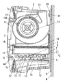
図2は、横向き姿勢で壁に設置される壁付けタイプの空気清浄器43の内部構造の一例を示している。この空気清浄器43は、放電部1及び対極部2を有し、放電部1から対極部2へ向かう放電により粉塵を帯電させる帯電手段3と、帯電された粉塵を捕集する集塵手段4と、これら帯電手段3及び集塵手段4へと空気を送る送風手段5と、これらを収納する箱型のハウジング7とを備えている。ハウジング7は壁表面Wに近接配置され、ハウジング7と壁表面Wとの間には、銅を含有させた不織布からなる導電性シートSが介在されており、導電性シートSと帯電手段3の電気回路とが電気的に接続されている。ハウジング7の後側上端部分には支持片部49が一体に形成され、家屋内の壁表面Wに取り付け固定された支持金具11に支持片部49を係上させることによって、壁表面Wにハウジング7は容易に引っ掛け支持されるようになっている。
【0012】
ハウジング7は、前面が開口した横長の箱型で、ハウジング7の開口した前面には、この開口全面を閉塞するグリル9が取り付けられている。ハウジング7の上側面部には空気吐出口10が、下側面部には空気吐出口10よりも開口面積の大きい空気取り入れ口7aが各々配設されている。また、グリル9の中程部分は若干前方に膨曲した前面部として形成され、この前面部の上下両側に細長状の空気取り入れ口7c、7bがそれぞれ形成されている。ここでは、空気取り入れ口7aと空気取り入れ口7bとが、帯電手段3及び集塵手段4の周辺付近に配置されている。上下両側の空気取り入れ口7c,7bは、横方向に長い長方形状に形成され、複数の横長スリットを並設した様相のガラリ状枠体が両空気取り入れ口7b,7cに各々着脱自在に取り付けられている。
【0013】
ハウジング7内には、プレフィルタ12、帯電手段3となる放電部1及び対極部2、集塵手段4が吸込側からこの順で収容配置され、機械的及び電気的に集塵するものとして、ハウジング7に内装されている。ここで、プレフィルタ12は比較的大きな粉塵を補集するものであり、帯電手段3は吸い込まれた粉塵を帯電させるもので、集塵手段4は粉塵を補集したり臭気分を脱臭したりするものである。帯電手段3及び集塵手段4は、両者間の隙間がその外周で閉塞されるように一体のケーシング6内に収容保持されている。ケーシング6は合成樹脂製一体成形品からなり、上下方向に開口する矩形箱型に形成されている。ケーシング6には、対極部2を保持する係止部8がケーシング6と一体に形成されており、ケーシング6はハウジング7に出し入れできるように、前後方向にスライド自在に係合保持されている。
【0014】
ケーシング6内には、放電部1となる複数本の放電線13が張設されていると共に、放電線13に対向配置されるように波型で多数の小孔を有したパンチングネットからなる対極部2が取り付けられている。放電線13は、例えば線形の細いタングステン線或いはピアノ線で形成されている。ここでは放電部1として、複数本の放電線13に代え、放電用の電極としての薄板状の打ち抜き針を用いてもよい。
【0015】
また、ケーシング6内に収容保持される集塵手段4は、極細の繊維が配合された濾材で形成される集塵部17と、該集塵部17の下流側面を覆う中敷シート(図示せず)と、中敷シートの下流側に充填される活性炭などの脱臭剤18とを備えている。図中の19は導電性を有するカバーリング材であり、ハウジング7の最下流側に装着されている。
【0016】
集塵手段4の下流側には、送風手段5としてシロッコファンからなるファン16Aが設置されている。ファン16Aはモータ14によって駆動されるもので、ファン16Aを駆動させると、空気取り入れ口7a,7b,7cからハウジング7内に空気が吸い込まれ、プレフィルタ12から帯電手段3及び集塵手段4を通過して、機械的及び電気的に浄化される。このときプレフィルタ12で粗いホコリが除去され、次の帯電手段3でホコリ等を帯電させる。この帯電したホコリはクーロン力で次の集塵手段4のフィルタ部に引き寄せられて除去され、臭い(ガス)成分はフィルタ内部の脱臭剤18に吸着される。フィルタを通過した空気は送風手段5を経て空気吐出口10からハウジング7の外部へ排出されて、家屋内の汚れた空気から粉塵や臭気等が補集、脱臭されるようになっている。
【0017】
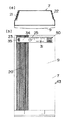
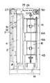
一方、図3は縦向き姿勢で床に設置される状態を示し、図4は横向き姿勢で床に設置される状態を示し、これらの据え置きタイプの空気清浄器43の基本構造は、前記図2の壁付けタイプの空気清浄器43と同様であり、対応する部分には同一符号を付しておく。
【0018】
図3、図4において、ハウジング7の前面部にグリル9を着脱自在に取り付けて外郭を構成してあり、グリル9の一側部には、図3(b)に示すように、格子部20が設けてあり、また、ハウジング7の一側面部の後部には図3(a)に示すように、別の格子部21が設けてあり、これら格子部20,21がファン16Aの回転による空気取り入れ口となっている。また、ハウジング7の他側面部に更に別の格子部22が設けてあり、この格子部22が浄化された空気吐出口となっている。
【0019】
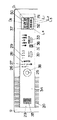
ハウジング7の最上部には、制御回路基板24(図4)が配置されている。この制御回路基板24には、ハウスダストや花粉粒子などの汚れ物質であるダストを検出するダストセンサ23、赤外線センサなどからなる人体感知センサ25、臭い成分やガス成分を検知する臭いセンサ31などがそれぞれ接続されている。
【0020】
ダストセンサ23、臭いセンサ31は、図5に示す操作パネル34に設けた格子部35、36にそれぞれ面して配置してある。格子部35、36は、それぞれ、空気取り入れ口となる格子部20の近くに配置され、空気取り入れ口に吸引される空気に乗ったダストをダストセンサ23が検知しやすいものとなっており、一方、空気中の臭い成分やガス成分を臭いセンサ31が検知しやすいものとなっている。
【0021】
一方、人体感知センサ25は操作パネル34に設けた光透過部38に面して配置してあり、人体を感知すると、感知信号が制御部41(図1)に送られて空気清浄器43を運転し、人体の感知がなくなると空気清浄器43を停止するように制御される。この人体感知センサ25を操作パネル34の中央に配置することで、空気清浄器43を縦置きに設置しても横置きに設置しても人体感知センサ25は中央に位置して、人体の感知がしやすくなっている。
【0022】
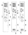
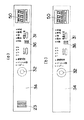
なお、図3、5に示す例では、ダストセンサ23、臭いセンサ31、人体感知センサ25がそれぞれ搭載されているが、図6(a)〜(c)に示すように、ダストセンサ23、臭いセンサ31、人体感知センサ25のすべてが搭載されていなくてもよく、また、図7(a)(b)に示すように、ダストセンサ23がなくてもよい。図中の32は紫外線センサである。
【0023】
操作パネル34は、縦置き用と横置き用との2種類があり、説明の文字等の向きが縦向き用と横向き用とで異なっている。従って、図3のような縦向きの場合には縦置き用の操作パネル34をグリル9の最上部に取り付け、図2、図4のような横向きの場合には横置き用の操作パネル34をグリル9の一側部に取り付けるようにすることによって、縦向き、横向きのいずれの場合でも説明の文字の方向が正しい方向となる。
【0024】
さらに、操作パネル34には、図5に示すように、フィルタ交換表示ランプ27、フィルタ交換表示ランプ27が点灯したときにこれを消灯するためのリセットボタン26、電極洗浄ランプ28、タイマ表示用LED29、タイマ切り釦30、風量切り替え釦33がそれぞれ配置してあり、これらは操作パネル34の表面側からの操作ができるようにしてある。なお電極洗浄ランプ28が点灯したときはグリル9を外して内部の電極部分を洗浄する。タイマ表示用LED29はタイマ表示時間の残り時間を表示するものであり、タイマ切り釦30を押してタイマ運転時間の残り時間表示を(1,2,3,4)→オフというようにセットできるものである。また風量切り替え釦33を押すことで、運転モードを自動モード、静音運転モード、標準運転モード→急速運転モード→オフという順番で切り替えることができるようになっている。またタイマ及び風量切替は付属のリモコンでも操作可能になっている。
【0025】
また、操作パネル34のダストセンサ23が設けられる部位とは反対側の端部には、ダストセンサ23により検知した室内のダストによる汚れ度表示と、臭いセンサ31により検知した室内汚れ度表示をする表示部50が設けてある。表示部50は、制御回路基板24(図4)に対して回転自在に挿入してある。これにより空気清浄器43を縦置きに設置しても横置きに設置しても表示部50の向きを縦向きにでき、表示が見やすくなるようにしてある。表示部50は操作パネル34に設けた汚れ度表示面37に対応して設けられており、汚れ度表示面37を通して表示部50を視認できるようにしてある。
【0026】
表示部50は、計測した数値を数字で表示する数字表示部51と、計測した数値を発光体で表示するモード表示部52とを備えている。数字表示部51は、7セグメントLEDや液晶表示等による3桁のデジタル表示とし、モード表示部52はランプ・LED等による4桁のレベル表示としてある。本発明では、ユーザーの通常使用時には、ダストセンサ23の汚れ度表示か臭いセンサ31の汚れ度表示のいずれか一方を数字表示部51で表示し、他方をモード表示部52で表示するようにしている。一方、出荷前の工場内でのモータ特性の検査時にあっては、空気清浄器43の特性項目の1つである回転体16の回転数を、数字表示部51又はモード表示部52のいずれか一方を利用して表示するようにしている。
【0027】
一方、空気清浄器43のモータ14には回転数検知手段40(図1)が搭載されている。この回転数検知手段40は、本来はモータ14の回転数信号(フィードバック信号)を出力してモータ14のフィードバック制御を行うために使用されるものであり、例えばホールIC等で構成されている。また制御部41には、回転数検知手段40からの回転数信号を取り込んで回転体16の単位時間当たりの回転数を計測するための計測回路45が設けられており、出荷前の工場内でのモータ特性検査時においては、計測回路45に上記フィードバック信号を取り込んで回転数を計測し、この計測した回転数をハウジング7の操作パネル34に設けた上記表示部50において表示できるようになっている。
【0028】
しかして、出荷前の工場にて空気清浄器43の特性項目の1つである回転体16の回転数の計測を行うにあたって、図2〜図4に示すように、空気清浄器43の外部から空気吐き出し口などを通して内部のファン16Aを見ることはできない場合にあっては、従来のような反射式の回転数測定装置による回転数の計測を行うことはできない。そこで本実施形態では、モータ14に搭載されているホールIC等の回転数検知手段40からのフィードバック信号(モータ14の回転数に応じて決まった信号)を制御部41に取り込み、判断・処理する。つまり、計測回路45によりフィードバック信号の周波数から1分間当たりの回転体16の単位時間当たりの回転数を計測して、表示部50に表示させる。これにより、出荷前の工場において、製品外部から回転体16が見えない場合であっても、モータ14からのフィードバック信号を利用して、空気清浄器43の特性の1つである回転体16の回転数を容易に計測・表示することが可能となる。
【0029】
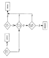
次に、回転数を表示する手段として、図8にその一例を示す。ちなみに、回転数の表示が通常のスイッチの入力操作で行われるようにすると、出荷後のユーザー使用時に不意に回転数が表示されてしまい、違和感を与えることがある。そこで工場での検査時には、通常のスイッチの入力操作とは異なる入力操作で回転数を表示させるようにしている。なお、以下の実施形態において回転数表示のために使用されるスイッチとしては、例えば、操作パネル34に設けられたリセットボタン26、タイマ切り釦30、風量切り替え釦33などのうちのいずれか2つを選択して使用することが考えられる。もちろん、操作パネル34上のスイッチ類には限らず、付属のリモコンに設けられているスイッチ類を使用することも考えられる。
【0031】
また、ユーザーによる通常使用時の誤作動防止を一層図るために、図8のフローチャートに示す手順で回転数を表示させる。図8のフローチャートでは、決められた2つ(或いは3つ以上)のスイッチ入力が同時に且つ所定時間以上あったときのみ回転数を表示させ、その後、スイッチ入力が無くなると、通常の表示に戻る。
【0032】
ところで、回転数を表示する方法として、図5に示す数字表示部51で表示させる方法と、モード表示部52で表示させる方法とが考えられる。
【0033】
数字表示部51では、計測した回転数そのものを表示することもできるが、モータ14からのフィードバック信号(通常は回転数の整数倍)を表示するようにしてもよい。ここで回転数の整数倍とは、モータ14に搭載される回転数検知手段40であるホールICの数の倍数であることを意味し、ホールICが例えば、3個設けた場合は回転数の3倍という意味である。もちろん、実際の回転体16の回転数をダイレクトで表示してもよい。
【0034】
なお、数字表示部51の桁数が少なくて、回転数を1度に表示しきれない場合にあっては、数字表示部51に2回以上に分けて表示することで対応できる。例えば数字表示部51の2桁D1,D2(図5)に1回目の表示(例えば、回転数の1桁目と2桁目のみ表示)を行い、その後、同じ数字表示部51の2桁D1,D2に2回目の表示(例えば、3桁目と4桁目のみ表示)を行う。このとき、数字表示部51のドットを点灯させたり、点滅させたりすることによって、1回目の表示と2回目の表示とを識別することが可能である。
【0035】
また、数字表示部51以外の表示(例えば、モード表示部52のランプ、LD等)を点灯あるいは、点滅することにより、どの桁が表示されているかを明確にしてもよい。例えば、モード表示部52を構成する4つのランプL1〜L4(図5)のうち、いずれか1つのランプL1を点灯させて数字表示部51に1回目の表示(例えば、回転数が4桁の場合に、1桁目と2桁目のみ表示)を行い、その後、他の1つのランプL2を点灯させて数字表示部51に2回目の表示(3桁目と4桁目のみ表示)を行うようにする。
【0036】
また、数字表示部51が仮に1桁であっても同様の表示を行うことによって、回転数を表示させることが可能になる。例えば、いずれか1つのランプ(例えばL1)を点灯させて数字表示部51に1回目の表示(例えば、回転数の1桁目のみ表示)を行い、その後、他の1つのランプ(例えばL2)を点灯させて数字表示部51に2回目の表示(2桁目のみ表示)を行い、この方法で4桁まで順に表示していくことによって4桁すべての回転数を1桁の数字表示部51にて表示可能となる。
【0037】
なお上記各表示方法において、数字表示部51において回転数の表示桁を切り換える際には、切り換え用のスイッチ入力を別に追加してもよい。
【0038】
一方、数字表示部51がない場合にあっては、ユーザーによる通常使用時にダストや臭いのレベルを表示するためのモード表示部52のみを利用して、計測した回転数を2進数で表示させることも可能である。例えば、モード表示部52を構成するランプやLEDが10個あれば、その点灯・消灯の組み合わせによって、1024通りの表示が可能になり、回転数として1024回転までの表示が可能となる。または10の位以上を表示する(1桁目を切り捨てる)ようにすれば、10240回転までの表示が可能となる。また、数字表示と同様に回転数の各位を表示させるのであれば、最低4個のモード表示部52があれば可能である。つまり、回転数の1桁目を4個のランプL1〜L4(図5)の点滅状態で2進数表示し、その後、2桁目を4個のランプL1〜L4の点滅状態で2進数表示し、このように回転数の各桁の数値を順番に切り換え表示することで、モード表示部52のみを利用して回転数が表示可能となる。なお、上記ランプL1〜L4の切り替えは、スイッチ入力で行ってもよく、また、自動的に切り換えるようにしてもよいものである。このように、数字表示部51が無くとも、2進数等の表示方法により通常のランプ等を利用して回転数の表示が可能となる。
【0039】
また、本例の制御部41は、回転体16が外力により拘束されたときには制御信号により回転体16を停止させるためのモータロック機能を備えている。本発明では、回転体16の回転数をモータ14からのフィードバック信号から検知する方式を採用しているので、フィードバック信号がない場合には、制御部41はモータ14が拘束されたと判断してモータ14ヘの制御信号を停止する。これにより、通常の拘束検知手段よりも早くしかも確実に、回転体16の拘束状態を検知でき、モータ14ヘの電力供給を停止することによって、モータロック状態となり、回転体16の回転が停止する。従って、異常時においても、より早く安全な状態にすることが可能となる。
【0040】
前記実施形態では、ファン16Aなどの回転体16が外部から見えない場所に配置されている場合を例示したが、もちろん、回転体16が外部から見える場合に配置されている場合においても、本発明の回転数の計測方法を同様に適用できるものである。
【0041】
【発明の効果】
上述のように請求項1記載の発明にあっては、空気を取り込むためのファン及びモータと、空気浄化用のフィルタと、これらを収納するハウジング等で構成され、上記モータにはモータをフィードバック制御するためにモータの回転数信号を出力する回転数検知手段が搭載されている空気清浄器において、上記モータの回転数検知手段からの回転数信号を取り込んでファン等の回転体の単位時間当たりの回転数を計測する計測回路と、計測した回転数を表示する表示部と、回転数表示のために決められた2つ以上のスイッチとを備え、上記決められた2つ以上のスイッチ入力が同時に且つ所定時間以上あったときのみ計測した回転数を表示させるように構成したので、出荷前の工場にて空気清浄器の特性項目の1つである回転体の回転数の計測を行うにあたって、モータに搭載されている回転数検知手段からの回転数信号(フィードバック信号)を取り込んで回転数を計測することによって、フィードバック制御が行われるモータの特性を利用して、回転数を容易に計測・表示することが可能となり、検査作業がはかどる。しかも、決められた2つ以上のスイッチ入力が同時に且つ所定時間以上あったときのみ計測した回転数を表示させるので、つまり、通常のスイッチの入力操作とは異なる入力操作で回転数を表示させるようにするので、ユーザーによる通常使用時の誤作動防止を図ることができる。
【0042】
また請求項2記載の発明は、請求項1記載の効果に加えて、外部から見えない場所に配置されている回転体の単位時間当たりの回転数を計測して表示するので、従来のような反射式の回転数測定装置による回転数の計測を行うことができない場合であっても回転数の計測・表示が可能となる。
【0043】
また請求項3記載の発明は、請求項1又は請求項2記載の効果に加えて、計測した回転数を数字で表示する数字表示部を備えているので、計測した回転数そのものを数字でダイレクトで表示することができる。また、出荷後のユーザー使用時に室内のダストや臭いのレベル表示用として使用される数字表示部がある場合には、この数字表示部を利用して回転数を表示することが可能となる。
【0044】
また請求項4記載の発明は、請求項1又は請求項2記載の効果に加えて、計測した回転数をランプ・LED等の発光体で表示するモード表示部を備えているので、計測した回転数を例えばランプ等の点滅によって2進数で表示させることが可能となる。また、出荷後のユーザー使用時にダストや臭いのレベルを表示するためのモード表示部がある場合には、このモード表示部を利用して回転数を表示することが可能となる。
【0045】
また請求項5記載の発明は、請求項1又は2記載の効果に加えて、回転数信号が入力されないときには回転体が外力により拘束されたと判断して制御信号により回転体を停止させるようにしたので、回転数信号によって通常の拘束検知手段よりも早くしかも確実に、回転体の拘束状態を検知でき、モータヘの電力供給を停止することによって、異常時においても、より早く安全な状態にすることが可能となる。
【図面の簡単な説明】
【図1】 本発明の実施形態の一例を示すブロック図である。
【図2】 同上の空気清浄器の一例の断面図である。
【図3】 同上の空気清浄器の他例を示し、(a)は平面図、(b)は正面図である。
【図4】 同上の空気清浄器のグリルを取り除いた状態の正面図である。
【図5】 同上の操作パネル付近の正面図である。
【図6】 同上の操作パネルの他例を示し、(a)はダストセンサがない場合の正面図、(b)は人体感知センサがない場合の正面図、(c)は臭いセンサがない場合の正面図である。
【図7】 (a)は同上の操作パネルの更に他例を示す正面図、(b)はダストセンサがない場合の正面図である。
【図8】 同上のファンの回転数を表示する手順の一例を示すフローチャートである。
【符号の説明】
7 ハウジング
14 モータ
16 ファン
16A 回転体
40 回転数検知手段
43 空気清浄器
50 表示部
51 数字表示部
52 モード表示部[0001]
BACKGROUND OF THE INVENTION
The present invention relates to an air purifier, and more particularly to a technique for inspecting the rotation speed of a fan, which is one of the characteristics of an air purifier, in a factory before shipment.
[0002]
[Prior art]
One of the characteristic items of the air cleaner is the rotational speed of the rotating body (fan or the like). Usually, the rotational speed of the rotating body is measured using a reflective rotational speed measuring device. Yes. That is, in a factory before shipment, a method is generally used in which light is applied to a rotating rotating body and the number of rotations per unit time is measured from the number of reflections.
[0003]
[Problems to be solved by the invention]
However, when the rotating body cannot be seen from the outside of the product, it cannot be measured by the conventional method of applying light to the rotating body. In addition to the above, there is a method for measuring the number of revolutions, but the measuring equipment is expensive and difficult to introduce easily.
[0004]
The present invention was invented in view of the problems of the above-described conventional example, and the object of the present invention is to use rotation for performing feedback control of a motor in a characteristic inspection in a factory before shipment. To provide an air purifier that can display the number of revolutions using a number signal (feedback signal), and can easily inspect the characteristics of the motor at low cost without capital investment. Another object is to provide an air purifier that can measure and display the number of rotations of the rotating body even when the rotating body is not visible from the outside of the product.
[0005]
[Means for Solving the Problems]
In order to solve the above problems, the present invention includes a
[0006]
In addition, since it is possible to measure and display the number of rotations per unit time of the rotating
[0007]
Moreover, it is preferable to provide the number display part 51 which displays the measured rotation speed with a number.
[0008]
Moreover, it is preferable to provide the
[0009]
When the rotational speed signal is not input, it is preferable to determine that the rotating
[0010]
DETAILED DESCRIPTION OF THE INVENTION
Hereinafter, the present invention will be described based on embodiments shown in the accompanying drawings.
[0011]
FIG. 2 shows an example of the internal structure of a wall-mounted
[0012]
The
[0013]
In the
[0014]
In the
[0015]
The dust collection means 4 accommodated and held in the
[0016]
On the downstream side of the dust collecting means 4, a
[0017]
On the other hand, FIG. 3 shows a state of being installed on the floor in a vertical posture, and FIG. 4 shows a state of being installed on the floor in a horizontal posture, and the basic structure of these stationary
[0018]
3 and 4, a
[0019]
A control circuit board 24 (FIG. 4) is disposed on the top of the
[0020]
The
[0021]
On the other hand, the human
[0022]
3 and 5, the
[0023]
There are two types of
[0024]
Further, as shown in FIG. 5, the
[0025]
Further, at the end of the
[0026]
The
[0027]
On the other hand, the rotational speed detection means 40 (FIG. 1) is mounted on the
[0028]
Therefore, when measuring the rotational speed of the
[0029]
Next, as a means of displaying the rotation speed,FIG.An example is shown in. By the way, if the display of the rotational speed is performed by a normal switch input operation, the rotational speed is unexpectedly displayed when used by the user after shipment, which may give an uncomfortable feeling. Therefore, at the time of inspection at the factory, the rotation speed is displayed by an input operation different from the normal switch input operation. In addition, as a switch used for the rotation speed display in the following embodiments, for example, any one of the
[0031]
In addition, in order to further prevent malfunction during normal use by users,FIG.Display the number of rotations according to the procedure shown inThe FIG.In this flowchart, the rotational speed is displayed only when the determined two (or three or more) switch inputs are simultaneously and for a predetermined time or more, and then the normal display is resumed when there is no switch input.
[0032]
By the way, as a method of displaying the number of rotations, a method of displaying on the number display unit 51 shown in FIG. 5 and a method of displaying on the
[0033]
The number display unit 51 can display the measured number of revolutions itself, but may display a feedback signal from the motor 14 (usually an integer multiple of the number of revolutions). Here, the integral multiple of the rotational speed means a multiple of the number of Hall ICs that are the rotational speed detection means 40 mounted on the
[0034]
In addition, when the number of digits of the number display unit 51 is small and the number of rotations cannot be displayed at a time, it can be dealt with by displaying the number display unit 51 twice or more. For example, the first display (for example, only the first and second digits of the number of rotations) are displayed on the two digits D1 and D2 (FIG. 5) of the number display unit 51, and then the two digits D1 of the same number display unit 51 are displayed. , D2 for the second time (for example, only the third and fourth digits are displayed). At this time, it is possible to distinguish between the first display and the second display by turning on or blinking the dots of the number display section 51.
[0035]
Further, it may be clarified which digit is displayed by lighting or blinking a display other than the number display unit 51 (for example, a lamp or LD of the mode display unit 52). For example, among the four lamps L1 to L4 (FIG. 5) constituting the
[0036]
In addition, even if the number display unit 51 has only one digit, it is possible to display the rotation speed by performing the same display. For example, any one lamp (for example, L1) is turned on to display the number display unit 51 for the first time (for example, only the first digit of the number of rotations), and then another one lamp (for example, L2). Is turned on to display the number display unit 51 for the second time (only the second digit is displayed). By sequentially displaying up to four digits by this method, all four digits of the number of revolutions are displayed as a one-digit number display unit 51. Can be displayed.
[0037]
In each of the above display methods, a switch input for switching may be added separately when switching the display digit of the number of revolutions in the number display unit 51.
[0038]
On the other hand, in the case where the number display unit 51 is not provided, only the
[0039]
Moreover, the
[0040]
In the above-described embodiment, the case where the rotating
[0041]
【The invention's effect】
As described above, in the first aspect of the present invention, the fan and motor for taking in air, a filter for purifying air, a housing for housing these, and the like are provided. In order to achieve this, in an air purifier equipped with a rotation speed detection means for outputting a rotation speed signal of a motor, the rotation speed signal from the rotation speed detection means of the motor is taken in per unit time of a rotating body such as a fan. A measurement circuit for measuring the number of rotations, and a display unit for displaying the measured number of rotations.And two or more switches determined for displaying the number of rotations, and configured to display the measured number of rotations only when the determined two or more switch inputs are simultaneously and for a predetermined time or more.Therefore, when measuring the rotational speed of the rotating body, which is one of the characteristic items of the air purifier, at the factory before shipment, the rotational speed signal (feedback signal) from the rotational speed detection means mounted on the motor is used. By taking in and measuring the number of revolutions, it becomes possible to easily measure and display the number of revolutions using the characteristics of the motor for which feedback control is performed, and the inspection work is accelerated.In addition, since the measured rotational speed is displayed only when two or more determined switch inputs are simultaneously and for a predetermined time or longer, the rotational speed is displayed by an input operation different from the normal switch input operation. Therefore, it is possible to prevent malfunction during normal use by the user.
[0042]
In addition to the effect of claim 1, the invention according to
[0043]
In addition to the effect of claim 1 or
[0044]
Moreover, in addition to the effect of Claim 1 or
[0045]
In addition to the effect of the first or second aspect, the invention according to
[Brief description of the drawings]
FIG. 1 is a block diagram illustrating an example of an embodiment of the present invention.
FIG. 2 is a cross-sectional view of an example of the above air cleaner.
FIGS. 3A and 3B show other examples of the above air cleaner, wherein FIG. 3A is a plan view and FIG. 3B is a front view.
FIG. 4 is a front view of the above air cleaner with the grill removed.
FIG. 5 is a front view of the vicinity of the operation panel.
6A and 6B show another example of the operation panel, wherein FIG. 6A is a front view without a dust sensor, FIG. 6B is a front view without a human body sensor, and FIG. 6C is a case without an odor sensor. FIG.
7A is a front view showing still another example of the operation panel of the above, and FIG. 7B is a front view in the case where there is no dust sensor.
FIG. 8 is a flowchart showing an example of a procedure for displaying the fan rotation speed of the above.The
[Explanation of symbols]
7 Housing
14 Motor
16 fans
16A Rotating body
40 Rotational speed detection means
43 Air Purifier
50 display section
51 Number display
52 Mode display
Claims (5)
Priority Applications (1)
| Application Number | Priority Date | Filing Date | Title |
|---|---|---|---|
| JP2000265848A JP3772655B2 (en) | 2000-09-01 | 2000-09-01 | air purifier |
Applications Claiming Priority (1)
| Application Number | Priority Date | Filing Date | Title |
|---|---|---|---|
| JP2000265848A JP3772655B2 (en) | 2000-09-01 | 2000-09-01 | air purifier |
Publications (2)
| Publication Number | Publication Date |
|---|---|
| JP2002066238A JP2002066238A (en) | 2002-03-05 |
| JP3772655B2 true JP3772655B2 (en) | 2006-05-10 |
Family
ID=18753050
Family Applications (1)
| Application Number | Title | Priority Date | Filing Date |
|---|---|---|---|
| JP2000265848A Expired - Fee Related JP3772655B2 (en) | 2000-09-01 | 2000-09-01 | air purifier |
Country Status (1)
| Country | Link |
|---|---|
| JP (1) | JP3772655B2 (en) |
Cited By (1)
| Publication number | Priority date | Publication date | Assignee | Title |
|---|---|---|---|---|
| KR200492808Y1 (en) * | 2019-06-05 | 2020-12-14 | (주)벨레 | air cleaner |
Families Citing this family (1)
| Publication number | Priority date | Publication date | Assignee | Title |
|---|---|---|---|---|
| CN111678243A (en) * | 2020-06-18 | 2020-09-18 | 东莞市豪铖电子科技有限公司 | A kind of robot air purifier and control method |
-
2000
- 2000-09-01 JP JP2000265848A patent/JP3772655B2/en not_active Expired - Fee Related
Cited By (1)
| Publication number | Priority date | Publication date | Assignee | Title |
|---|---|---|---|---|
| KR200492808Y1 (en) * | 2019-06-05 | 2020-12-14 | (주)벨레 | air cleaner |
Also Published As
| Publication number | Publication date |
|---|---|
| JP2002066238A (en) | 2002-03-05 |
Similar Documents
| Publication | Publication Date | Title |
|---|---|---|
| KR100507996B1 (en) | Separable air cleaner | |
| TWI617775B (en) | Air cleaner | |
| JP3697950B2 (en) | air purifier | |
| KR102321002B1 (en) | Air cleaner and control method thereof | |
| KR20150112699A (en) | Air cleaning apparatus | |
| JP5222050B2 (en) | Air conditioner | |
| CN105371377A (en) | air purifier | |
| JP3772655B2 (en) | air purifier | |
| JP3574753B2 (en) | Air cleaner | |
| KR20130102500A (en) | Air cleaner | |
| JP2001062228A (en) | Air cleaner | |
| JP2001108287A (en) | Air cleaner | |
| JP2015232433A (en) | Air cleaner | |
| JP2006122644A (en) | Air purifier pollution degree sensing device and method | |
| KR100602697B1 (en) | air cleaner | |
| JP3106959B2 (en) | Air cleaner | |
| JPS63147513A (en) | Air cleaner | |
| JPH105519A (en) | Air purifier with air status display function | |
| CN100572949C (en) | air purifier | |
| JPH0636879B2 (en) | Air cleaner | |
| JP6435171B2 (en) | Air conditioner | |
| KR101158595B1 (en) | Air cleaner | |
| JP2000167332A (en) | Air purifier | |
| JPH08131742A (en) | Air cleaner | |
| JP2002013793A (en) | Air conditioner |
Legal Events
| Date | Code | Title | Description |
|---|---|---|---|
| A621 | Written request for application examination |
Free format text: JAPANESE INTERMEDIATE CODE: A621 Effective date: 20040819 |
|
| A977 | Report on retrieval |
Free format text: JAPANESE INTERMEDIATE CODE: A971007 Effective date: 20050829 |
|
| A131 | Notification of reasons for refusal |
Free format text: JAPANESE INTERMEDIATE CODE: A131 Effective date: 20051025 |
|
| A521 | Request for written amendment filed |
Free format text: JAPANESE INTERMEDIATE CODE: A523 Effective date: 20051226 |
|
| TRDD | Decision of grant or rejection written | ||
| A01 | Written decision to grant a patent or to grant a registration (utility model) |
Free format text: JAPANESE INTERMEDIATE CODE: A01 Effective date: 20060124 |
|
| A61 | First payment of annual fees (during grant procedure) |
Free format text: JAPANESE INTERMEDIATE CODE: A61 Effective date: 20060206 |
|
| S111 | Request for change of ownership or part of ownership |
Free format text: JAPANESE INTERMEDIATE CODE: R313113 |
|
| R350 | Written notification of registration of transfer |
Free format text: JAPANESE INTERMEDIATE CODE: R350 |
|
| FPAY | Renewal fee payment (event date is renewal date of database) |
Free format text: PAYMENT UNTIL: 20100224 Year of fee payment: 4 |
|
| LAPS | Cancellation because of no payment of annual fees |