JP3772635B2 - Performance learning system - Google Patents
Performance learning system Download PDFInfo
- Publication number
- JP3772635B2 JP3772635B2 JP2000086185A JP2000086185A JP3772635B2 JP 3772635 B2 JP3772635 B2 JP 3772635B2 JP 2000086185 A JP2000086185 A JP 2000086185A JP 2000086185 A JP2000086185 A JP 2000086185A JP 3772635 B2 JP3772635 B2 JP 3772635B2
- Authority
- JP
- Japan
- Prior art keywords
- data
- determined whether
- performance
- value
- midi
- Prior art date
- Legal status (The legal status is an assumption and is not a legal conclusion. Google has not performed a legal analysis and makes no representation as to the accuracy of the status listed.)
- Expired - Fee Related
Links
Images


Landscapes
- Electrophonic Musical Instruments (AREA)
- Electrically Operated Instructional Devices (AREA)
- Reverberation, Karaoke And Other Acoustics (AREA)
Description
【0001】
【発明の属する技術分野】
本発明は、演奏教習システムに関する。
【0002】
【従来の技術】
インターネット等の通信手段を介して曲データを受信してRAM等のメモリにダウンロードし、その曲データに基づいて演奏教習を行うことが提案されている。例えば、鍵盤楽器等で演奏教習を行う場合には、各鍵の下部に設けられた発光素子によって受信した曲データの音高データに対応する鍵を照光して、演奏すべき鍵のナビゲーションを行う構成になっている。
【0003】
【発明が解決しようとする課題】
しかしながら、上記従来の提案においては、曲データサーバ4から演奏教習用の曲データをダウンロードしても、その曲データがその鍵盤楽器等の機能やユーザすなわち演奏者の演奏技術では演奏できないほど高度のものであったり、逆に演奏者が大人である程度の熟練者であるにもかかわらず、幼児向けの曲データが配信されるおそれがある。
【0004】
本発明の課題は、インターネット等の通信手段を介して配信を受けた曲データに基づいて演奏教習を行う場合に、演奏装置や演奏者に最適な曲データの配信が得られるようにすることである。
【0005】
【課題を解決するための手段】
請求項1に記載の演奏教習システムは、曲毎に複数の演奏教習用データを格納するサーバシステム(実施形態においては、図1の曲データサーバ4に対応する)及び通信手段(実施形態においては、図1のネットワーク3に対応する)を介して当該サーバシステムに接続可能な複数のクライアントシステム(実施形態においては、図1のパソコン2及び楽器1に対応する)からなる演奏教習システムであって、
前記サーバシステムは、前記通信手段を介して接続された任意のクライアントシステムから当該クライアントシステムに入力された演奏技術のレベルを示す情報とともに任意の曲についての演奏教習用データの配信を要求された際は、前記複数の演奏教習用データの中から当該クライアントシステムに入力された演奏技術のレベルに対応した演奏教習用データを前記任意の曲についての演奏教習用データとして配信し、前記クライアントシステムは配信された前記演奏教習用データに基づき演奏ガイド及び演奏判定の少なくともいずれか一方を含む演奏教習を行う。
【0007】
請求項1に記載の発明によれば、曲毎に複数の演奏教習用データを格納するサーバシステムから演奏教習用データの配信を受ける場合に、クライアントシステムに入力された演奏技術のレベルに適合した演奏教習用データの配信を受け、演奏ガイド及び演奏判定の少なくともいずれか一方を含む演奏教習を行う。
【0008】
【発明の実施の形態】
以下、本発明による実施形態について図を参照して説明する。
図1は、本発明におけるシステム構成を示している。鍵盤を有する楽器1は、各鍵に対応してLEDの発光素子が設けられている。また、RS232C等の通信ケーブルによってパソコン2に接続され、MIDI形式の曲データの授受を行っている。ネットワーク3は、インターネットやその他の通信回線であり、パソコン2と曲データサーバ4との間をオンライン接続する。曲データサーバ4は、多数の曲データのデータベースを備えており、パソコン2からの要求に応じて、曲データを配信する。すなわち、図1に示すシステムは、各曲データごとに複数種類のアレンジをもつ演奏教習用の多数の曲データを格納する曲データサーバ4及びネットワーク3を介して当該曲データサーバ4に接続可能なパソコン2及び楽器1で構成された複数のクライアントシステムからなる演奏教習システムである。
【0009】
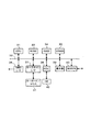
図2は、図1における楽器1の構成を示すブロック図である。CPU11には、システムバス12を介して、ROM13、RAM14、キースキャンインターフェース15、LEDC(LEDコントローラ)16、音源17、MIDIインターフェース18が接続され、これらと間でデータ及びコマンドの授受をおこなっている。ROM13は、CPU11が実行する制御プログラム、初期データ等を格納している。RAM14は、CPU11のワークエリアであり、システムバス12を介して授受するデータを一時的に記憶する。
【0010】
キースキャンインターフェース15は、鍵盤19に接続され、CPU11からのキースキャンコマンドに応じて各鍵のオン・オフ状態を走査して検出する。LEDC16は、鍵盤19の各鍵の下側に設けられている発光素子であるLED20に接続され、CPU11の点灯指令又は消灯指令に応じてLED20の駆動を制御する。音源17は、A/Dコンバータ、アンプ、スピーカ等からなるサウンドシステム21に接続され、CPU11の発音指令又は消音指令に応じてサウンドシステム21の発音又は消音を制御する。
【0011】
MIDIインターフェース18は、MIDI形式の曲データのイベントをパソコン2から受信してRAM14の曲データバッファにストアする。CPU11は、曲データに応じて演奏教習を行う。すなわち、ノートオンのイベントに応じて、その音高に対応する鍵のLEDを点灯させる。また、そのイベントのベロシティについても演奏教習の機能をもっている場合には、ベロシティに応じて、例えばLEDの点滅の速さを制御してもよい。
【0012】
図3は、パソコン2のシステム構成を示している。CPU31には、システムバス32を介して、ROM33、RAM34、VRAM35、MIDIインターフェース36、キースキャンインターフェース37、HDC(ハードディスクコントローラ)38、表示部39、及びMODEM40が接続されている。CPU31は、これらと間でデータ及びコマンドの授受をおこなってパソコン2全体を制御している。
【0013】
ROM33は、CPU31が実行する制御プログラム、初期データ等を格納している。RAM34は、CPU31のワークエリアであり、システムバス32を介して授受するデータを一時的に記憶する。VRAM35は、表示部39に表示する1フィールド分の画像データ(ビットマップデータ)を記憶する。MIDIインターフェース36は、CPU31の指令に応じて、楽器1のCPU11との間で通信制御を行い、MIDI形式の曲データを転送するとともに、楽器1の鍵盤19の押鍵状態を受信する。
【0014】
キースキャンインターフェース37は、キーボード及びマウスからなる操作部41に接続され、CPU11からのキースキャンコマンドに応じて各キーのオン・オフ及びマウスの移動及びクリックの状態を走査して検出する。HDC38は、外部記憶媒体であるHD(ハードディスク)42を収容し、CPU31の指令に応じて曲データサーバ4からダウンロードした曲データの書込み、及びダウンロードした曲データの読出しを制御する。表示部39は、曲データのリスト画面、ダウンロード画面、曲データの再生画面等を表示する。MODEM40は、CPU31の通信接続指令に応じてネットワーク3に接続する通信プロトコルを実行する。
【0015】
次に、図1に示したシステム構成の動作について詳細に説明する。
まず、曲データサーバ4の動作について説明する。
図4〜図8は、サーバ内のメモリエリアマップを示す図である。図4に示すように、サーバのメモリエリアには、バッファエリア、RGB(カラー表示楽譜)エリア、CMD(演奏ガイド用コマンド)エリア、MID(曲データ)エリア、SET(再生情報)エリア、PAT(伴奏パターン)エリアがある。
【0016】
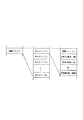
バッファエリアには、ヘッダデータとともに、他のエリアのデータ、すなわちRGBデータ、CMDデータ、MIDデータ、SETデータ、及びPATデータが一時的にストアされる。ヘッダデータは、バッファエリア内のすべてのファイル数、RGB用、CMD用、MID用、SET用、及びPAT用のヘッダデータがストアされる。例えば、RGB用のヘッダデータとしては、ファイル名、スタートアドレス、エンドアドレスがある。他のヘッダデータも同様である。
【0017】
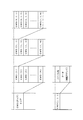
図5は、RGBエリアの楽譜データのレイヤ構造を示している。最上位のレイヤは、複数(例えばN個)の曲に対応する楽譜データ、RGB(1)、RGB(2)、RGB(3)、… RGB(N)で構成されている。その下位の各曲ごとのレイヤ、例えばRGB(1)の下位レイヤは、複数の楽器の機種に対応する楽譜データ、RGB(1、1)、RGB(1、2)、RGB(1、3)、… RGB(1、N)で構成されている。さらにその下位の各機種ごとのレイヤ、例えばRGB(1、1)の下位レイヤは、複数のスキル(ユーザの熟練度)に対応する楽譜データ、RGB(1、1、1)、RGB(1、1、2)、RGB(1、1、3)、… RGB(1、1、N)で構成されている。そして、各スキルのデータ、例えばRGB(1、1、1)のデータは、ファイル名及び楽譜データで構成されている。
【0018】
図6は、PATエリアの伴奏パターンデータのレイヤ構造を示している。最上位のレイヤは、複数(N個)の曲に対応する伴奏パターンデータ、PAT(1)、PAT(2)、PAT(3)、… PAT(N)で構成されている。その下位の各曲ごとのレイヤ、例えばPAT(1)の下位レイヤは、複数の楽器の機種に対応する伴奏パターンデータ、PAT(1、1)、PAT(1、2)、PAT(1、3)、… PAT(1、N)で構成されている。さらにその下位の各機種ごとのレイヤ、例えばPAT(1、1)の下位レイヤは、複数のスキル(ユーザの熟練度)に対応する伴奏パターンデータ、PAT(1、1、1)、PAT(1、1、2)、PAT(1、1、3)、… PAT(1、1、N)で構成されている。そして、各スキルのデータ、例えばPAT(1、1、1)のデータは、ファイル名及び伴奏パターンデータで構成されている。
【0019】
この伴奏パターンデータは、後述するように、パソコンを介して楽器にダウンロードされて、楽器のユーザーエリアにストアされるが、楽器の機種によってはユーザーエリアをもっていないものもある。例えば、図6におけるPAT(1、3)に対応する機種にはユーザーエリアがない。したがって、その伴奏パターンデータは「なし」となっている。
【0020】
図7は、CMDエリアの描画コマンドデータのレイヤ構造を示している。最上位のレイヤは、複数(N個)の曲に対応する描画コマンド、CMD(1)、CMD(2)、CMD(3)、… CMD(N)で構成されている。その下位の各曲ごとのレイヤ、例えばCMD(1)の下位レイヤは、複数の楽器の機種に対応する描画コマンド、CMD(1、1)、CMD(1、2)、CMD(1、3)、…CMD(1、N)で構成されている。さらにその下位の各機種ごとのレイヤ、例えばCMD(1、1)の下位レイヤは、複数のスキル(ユーザの熟練度)に対応する描画コマンド、CMD(1、1、1)、CMD(1、1、2)、CMD(1、1、3)、… CMD(1、1、N)で構成されている。そして、各スキルのデータ、例えばCMD(1、1、1)のデータは、ファイル名及び描画コマンドで構成されている。
【0021】
描画コマンドのデータは、楽譜を構成する複数の音符ごとに用意されており、図8に示すように、WAKU(0)、WAKU(1)、…、WAKU(N)からなる複数のデータで構成されている。そして各データは、表示位置を示す座標(x,y)、大きさ(形状が四角の場合には、高さ及び幅)、形状(四角、丸)、色、及び外枠線(幅、種類)のデータで構成されている。
【0022】
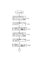
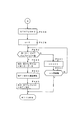
次に、曲データサーバの動作についてフローチャートを参照して説明する。図9は、曲データサーバのメインフローである。パソコンから受信があるか否かを判別し(ステップSA1)、受信があったときは曲番号を受信したか否かを判別する(ステップSA2)。曲番号を受信したときは、レジスタMELODYにその受信データをセットする(ステップSA3)。そして、メロディフラグMFに1をセットする(ステップSA4)。ステップSA2において、受信データが曲番号でない場合には、受信データが環境データであるか否かを判別する(ステップSA5)。環境データである場合には、環境データの中の機種データをレジスタにセットし、環境データの中のスキルデータをレジスタSKILLにセットする(ステップSA6)。そして、環境フラグKFに1をセットする(ステップSA7)。
【0023】
次に、MF及びKFがともに1であるか否かを判別する(ステップSA8)。ともに1でない場合には、ステップSA1に移行して、受信データの有無を判別する。MF及びKFがともに1である場合には、ファイル作成処理を実行する(ステップSA9)。次に、その作成したファイルをパソコンに送信する送信処理を実行し(ステップSA10)、MF及びKFをともに「0」にリセットする(ステップSA11)。そして、ステップSA1に移行して、受信データの有無を判別する。
【0024】
図10〜図12は、図9のフローにおけるステップSA9のファイル作成処理のフローである。図10のフローにおいて、RGBエリア内でRGB(MELODY、KISHU、SKILL)のファイルを指定する(ステップSB1)。次に、バッファ内に指定ファイルのデータをストアする(ステップSB2)。さらに、ヘッダ部にファイル名、スタートアドレス、エンドアドレスを書込む(ステップSB3)。また、CMDエリア内のCMD(MELODY、KISHU、SKILL)のファイルを指定する(ステップSB4)。次に、バッファ内に指定ファイルのデータをストアする(ステップSB5)。さらに、ヘッダ部にファイル名、スタートアドレス、エンドアドレスを書込む(ステップSB6)。
【0025】
次に、図11のフローにおいて、MIDエリア内のMID(MELODY、KISHU、SKILL)のファイルを指定する(ステップSB7)。次に、バッファ内に指定ファイルのデータをストアする(ステップSB8)。さらに、ヘッダ部にファイル名、スタートアドレス、エンドアドレスを書込む(ステップSB9)。また、SETエリア内のSET(MELODY、KISHU、SKILL)のファイルを指定する(ステップSB10)。その指定したデータがあるか否かを判別し(ステップSB11)、データがある場合にはバッファ内に指定ファイルのデータをストアする(ステップSB12)。さらに、ヘッダ部にファイル名、スタートアドレス、エンドアドレスを書込む(ステップSB13)。データがない場合には当然、データのストア及びヘッダ部の書込みは行わない。
【0026】
次に、図12のフローにおいて、PATエリア内のPAT(MELODY、KISHU、SKILL)のファイルを指定する(ステップSB14)。その指定したデータがあるか否かを判別し(ステップSB15)、データがある場合にはバッファ内に指定ファイルのデータをストアする(ステップSB16)。さらに、ヘッダ部にファイル名、スタートアドレス、エンドアドレスを書込む(ステップSB17)。データがない場合には当然、データのストア及びヘッダ部の書込みは行わない。この後、バッファ内に書込まれたファイル数Nをヘッダ部に書込み(ステップSA18)、図9のメインフローに戻る。
【0027】
図13は、図1に示したパソコン2のメモリエリアを示している。メモリエリアは、バッファエリア、楽譜エリア、描画コマンドエリア、MIDIデータエリア、伴奏曲設定情報エリア、伴奏パターンエリアで構成されている。また各エリアは、ヘッダ部及びファイル部で構成されている。
【0028】
次に、パソコンの動作について図3に示したCPU31のフローチャート及び表示部39の画面を参照して説明する。図14は、CPU31のメインフローである。所定のイニシャライズ処理(ステップPA1)の後、図15に示すメニュー画面を表示する(ステップPA2)この画面には、「曲ダウンロード」及び「曲再生」のアイコンスイッチが表示される。そして、アイコンスイッチがオンされたか否かを判別する(ステップPA3)。
【0029】
アイコンスイッチがオンされたときは、ダウンロードのアイコンスイッチがオンされたか、又は再生のアイコンスイッチがオンされたかを判別する(ステップPA4)。ダウンロードのアイコンスイッチがオンされたときはダウンロード処理を実行し(ステップPA5)、再生のアイコンスイッチがオンされたときは再生処理を実行する(ステップPA6)。ダウンロード処理又は再生処理の後は、ステップPA2に移行してメニュー画面を表示する。
【0030】
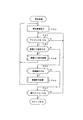
図16は、図14のフローにおけるステップPA5のダウンロード処理のフローである。まず、図17に示すダウンロードメニュー画面を表示する(ステップPB1)。すなわち、「曲リスト」、「環境設定」、「送信」、及び「戻る」のアイコンスイッチを表示する。そして、アイコンスイッチがオンされたか否かを判別する(ステップPB2)。アイコンスイッチがオンされたときは、そのオンされたアイコンスイッチに応じた処理を行う。
【0031】
曲リストアイコンスイッチがオンされたか否かを判別し(ステップPB3)、オンされたときは曲選択処理を実行する(ステップPB4)。環境設定アイコンスイッチがオンされたか否かを判別し(ステップPB5)、このアイコンがオンされたときは環境設定処理を実行する(ステップPB6)。曲選択処理又は環境設定処理を実行した後は、ステップPB1に移行して図17のメニュー画面を表示する。
【0032】
曲リスト及び環境設定のアイコンスイッチがオンされない場合には、送信アイコンスイッチがオンされたか否かを判別し(ステップPB7)、オンされたときは送受信処理を実行する(ステップPB8)。この後は、設定内容をクリアして(ステップPB9)、図14のメインフローに戻る。送信アイコンスイッチがオンされない場合には、戻りアイコンスイッチがオンされたか否かを判別し(ステップPB)、オンされたときは設定内容をクリアして(ステップPB9)、図14のメインフローに戻る。戻りアイコンがオンされない場合には、ステップPB1に移行する。
【0033】
図18は、図16のフローにおけるステップPB4の曲選択処理のフローである。まず、図19に示す曲リストを表示する(ステップPC1)。この画面には、曲リストの他に「OK」アイコンスイッチ及び「戻る」アイコンスイッチが表示される。次に、いずれかの曲リストがオンされたか否かを判別し(ステップPC2)、オンされたときはその曲番号をレジスタMELODYにセットする(ステップPC3)。
【0034】
曲リストがオンされない場合には、アイコンスイッチがオンされたか否かを判別する(ステップPC4)。オンされたときは、戻りアイコンスイッチがオンされたのか、又はOKアイコンスイッチがオンされたかを判別する(ステップPC5)。戻りアイコンスイッチがオンされたときは、MELODYにセットされている曲番号をクリアして(ステップPC6)、図16のフローに戻る。OKアイコンスイッチがオンされたときは、MELODYにセットされている曲番号を保持した状態で、図16のフローに戻る。
【0035】
図20は、図16のフローにおけるステップPB6の環境設定処理のフローである。まず、図21に示す環境設定画面を表示する(ステップPD1)。この画面には、楽器の機種名を表示するエリアと演奏者のスキルを表示するエリアがあり、「戻る」アイコンスイッチ及び「OK」アイコンスイッチが表示される。環境設定画面を表示した後、キーボードから文字等のデータ入力があるか否かを判別する(ステップPD2)。
【0036】
入力があったときは、そのデータが機種名であるか否かを判別する(ステップPD3)。機種名である場合には、その機種名のデータをレジスタKISHUにセットする(ステップPD4A)。そして、KISYUのデータを送信バッファにストアする(ステップPD4B)。また、KISHUにセットされた機種名を画面の対応するエリアに表示する(ステップPD5)。入力されたデータが機種名でない場合すなわちそのデータが演奏レベル(スキル)である場合には、その演奏レベルのデータをレジスタSKILLにセットする(ステップPD6A)。そして、SKILLのデータを送信バッファにストアする(ステップPD6B)。また、SKILLにセットされた演奏レベルを画面の対応するエリアに表示する(ステップPD7)。機種名又は演奏レベルを表示した後は、ステップPD2に移行してデータ入力を判別する。
【0037】
キーボードからデータ入力がない場合には、アイコンスイッチがオンされたか否かを判別する(ステップPD8)。アイコンスイッチがオンされたときは、オンされたのが戻りアイコンスイッチであるか、又はOKアイコンスイッチであるかを判別する(ステップPD9)。オンされたのが戻りアイコンスイッチである場合には、設定内容をクリアして(ステップPD10)、図16のフローに戻る。オンされたのがOKアイコンスイッチである場合には、設定内容を保持した状態で図16のフローに戻る。
【0038】
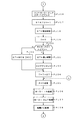
図22及び図23は、図16のフローにおけるステップPB8の送受信処理のフローである。図22において、送信バッファに送信データがあるか否かを判別し(ステップPE1)、送信データがある場合には送信処理を実行する(ステップPE2)。送信バッファ内に楽器の機種名のデータやスキルのデータがある場合には、それを環境情報として曲データサーバに送信する。そして、送信が終了したか否かを判別する(ステップPE3)。送信データが残っている場合には送信処理を続行するが、送信が終了したときは受信データがあるか否かを判別する(ステップPE4)。
受信データがある場合には、その受信データを図13に示した受信バッファへストアし(ステップPE5)、図24に示すダウンロード中の画面を表示する(ステップPE6)。そして、受信データが終了したか否かを判別する(ステップPE7)。終了していない場合には、ステップPE4に移行して受信データの有無を判別する。
【0039】
受信データが終了したときは、受信バッファ内のヘッダ部のファイル数をレジスタNにセットする(ステップPE8)。次に、ポインタnを1にセットし(ステップPE9)、nの値をインクリメントしながらnに対応する受信バッファ内のデータを対応するエリアにストアする。
すなわち、nが1であるか否かを判別し(ステップPE10)、nが1である場合には、ヘッダ部のn番目のスタートアドレス及びエンドアドレスで指定されるデータを楽譜データエリアにストアする(ステップPE11)。
nが1でない場合には、図23のフローにおいて、nが2であるか否かを判別し(ステップPE12)、nが2である場合には、ヘッダ部のn番目のスタートアドレス及びエンドアドレスで指定されるデータをCMDデータエリアにストアする(ステップPE13)。
【0040】
nが2でない場合には、nが3であるか否かを判別し(ステップPE14)、nが3である場合には、ヘッダ部のn番目のスタートアドレス及びエンドアドレスで指定されるデータをMIDIデータエリアにストアする(ステップPE15)。
nが3でない場合には、nが4であるか否かを判別し(ステップPE16)、nが4である場合には、ヘッダ部のn番目のスタートアドレス及びエンドアドレスで指定されるデータを伴奏設定情報データエリアにストアする(ステップPE17)。
nが4でない場合には、nが5であるか否かを判別し(ステップPE18)、nが5である場合には、ヘッダ部のn番目のスタートアドレス及びエンドアドレスで指定されるデータをパターン情報データエリアにストアする(ステップPE19)。
【0041】
指定されるデータを対応するエリアにストアした後は、図22のステップPE20においてnの値をインクリメントする。そして、nの値がNの値(この場合は、N=5)より大きくなったか否かを判別する(ステップPE21)。nの値がNの値以下である場合には、ステップPE10に移行する。nの値がNの値より大きい値(この場合は、n=6)になったときは、クオンタイズ処理を実行して(ステップPE22)、図16のフローに戻る。
【0042】
図25及び図26は、クオンタイズ処理のフローである。最初にアドレスレジスタADにMIDIデータエリアのスタートアドレスをセットする(ステップPF1)。そして、ADのアドレスをインクリメントしながらMIDIデータエリアを検索する。
すなわち、MIDI(AD)のデータがガイドチャンネル(コードをナビゲートするチャンネル)のノートオンイベントであるか否かを判別する(ステップPF2)。そのデータがガイドチャンネルのノートオンイベントでない場合には、ADのアドレスをインクリメントする(ステップPF3)。このインクリメントしたADのアドレスがエンドアドレスより大きい値になったか否かを判別する(ステップPF4)。エンドアドレス以下である場合には、ステップPF2に移行してMIDI(AD)のデータの内容を判別する。
【0043】
MIDI(AD)のデータがガイドチャンネルのノートオンイベントである場合には、タイムレジスタTの値を0にリセットする(ステップPF5)。次に、ポインタmの値を1にセットし(ステップPF6)、ポインタnの値を0にセットする(ステップPF7)。そして、ノートオンイベントのノートデータをレジスタNOTE(n)にセットする(ステップPF8)。次に、MIDI(AD+m)のデータの内容を判別する(ステップPF9)。
【0044】
このデータがタイムデータである場合には、Tの値にそのタイムデータすなわちMIDI(AD+m)のデータを加算する(ステップPF10)。そして、Tの値が所定タイムより大きいか否かを判別する(ステップPF11)。所定タイムとは、複数のノートオンイベントがコードであるか否かを判別する閾値である。タイムデータが閾値より小さい複数のノートオンイベントがコードの候補となる。Tの値が所定タイム以下である場合には、mの値をインクリメントする(ステップPF12)。このときAD+mのアドレスがエンドアドレスより大きいか否かを判別する(ステップPF13)。エンドアドレス以下である場合には、ステップPF9に移行して、MIDI(AD)のデータの内容を判別する。
【0045】
MIDI(AD+m)のデータがイベントである場合には、さらにそのMIDI(AD+m)のイベントがガイドチャンネルのノートオンイベントであるか否かを判別する(ステップPF14)。ガイドチャンネルのノートオンイベントである場合には、そのイベントは前のアドレスのイベントとコードを構成する可能性をもつコード候補である。そこで、nの値をインクリメントして(ステップPF15)、そのイベントのノートデータをNOTE(n)にセットする(ステップPF16)。次に、ステップPF12に移行してmの値をインクリメントする。
【0046】
ステップPF11においてTの値が所定タイム以下であり、かつ、次のデータがガイドチャンネルのノートオンイベントである限り、上記ループ処理を繰り返す。次のデータがガイドチャンネルのノートオンイベントでない場合、例えば、コントロールチェンジ等の制御データである場合には、ステップPF12に移行してmの値をインクリメントする。ステップPF11において、Tの値が所定タイムより大きくなった場合には、NOTE(0)〜NOTE(n)にセットした複数のノートオンイベントでコードが成立するか否かを判別する(ステップPF17)。コードが成立しない場合には、NOTE(0)〜NOTE(n)のデータをクリアして(ステップPF18)、ステップPF3に移行してADのアドレスをインクリメントする。
【0047】
ステップPF17においてコードが成立した場合には、図26のフローにおいて、MIDI(AD)のイベントをコードデータに変更する(ステップPF19)。次に、NOTE(1)〜(n)に対するノートオフイベントを削除し(ステップPF20)、タイムデータを変更する(ステップPF21)。すなわち、コードを構成する複数のノートオンイベントを1つのコードデータに変更したので、そのコードイベント対応する1つのノートオフイベントのみを残して、他のノートオフイベントを削除し、その削除によってタイムデータ(デルタタイム)を変更する。また、コード化及びノートオフイベントの削除に応じて、ADのアドレスにmを加算して次のアドレスを指定する(ステップPF22)。そして、図25のステップPF3に移行してADのアドレスをインクリメントする。ステップPF4において、ADのアドレスがエンドアドレスより大きくなった場合には、クオンタイズ処理のフローを終了する。
【0048】
図27は、図14のメインフローにおけるステップPA6の再生処理のフローである。まず、図28に示す再生画面を表示する(ステップPG1)。この画面には、「楽譜ナビ設定」、「楽譜表示」、及び「戻る」アイコンスイッチが表示される。次に、アイコンスイッチがオンされたか否かを判別する(ステップPG2)。いずれかのアイコンスイッチがオンされたときは、そのアイコンに応じた処理を行う。
【0049】
楽譜ナビ設定のアイコンスイッチがオンされたか否かを判別し(ステップPG3)、このアイコンがオンされたときは楽譜ナビ設定処理を実行する(ステップPG4)。あるいは楽譜表示のアイコンスイッチがオンされたか否かを判別し(ステップPG5)、このアイコンがオンされたときは楽譜表示処理を実行する(ステップPG6)。楽譜ナビ設定処理又は楽譜表示処理の後は、ステップPG1に移行して再生画面を表示する。楽譜ナビ設定及び楽譜表示のアイコンスイッチがどちらもオンされない場合には、戻りのアイコンスイッチがオンされたか否かを判別し(ステップPG7)、このアイコンがオンされたときは図14のメインフローに戻る。
【0050】
図29は、図27のフローにおけるステップPG4の楽譜ナビ設定処理のフローである。まず、図30(1)に示す楽譜ナビ設定画面を表示する(ステップPH1)。この画面には、楽譜ナビゲーションを行うか否かを設定する楽譜ナビゲーション用のラジオボタン、次の音符を指示する画像を点滅するか否かを設定する音符点滅用のラジオボタン、及び、演奏結果の間違いを表示するか否かを設定する間違い表示用のラジオボタン、並びに戻りのアイコンスイッチが表示される。
【0051】
そして、いずれかのラジオボタンが操作されたか否かを判別する(ステップPH2)。いずれかのラジオボタンが操作された場合には、その操作されたラジオボタンに応じた処理を行う。すなわち、楽譜ナビゲーション用のラジオボタンが操作されたか否かを判別し(ステップPH3)、このラジオボタンが操作されたときは、オン側の操作であるか又はオフ側の操作であるかを判別する(ステップPH4)。オン側の操作である場合には、フラグGNABFを1(楽譜ナビオン)にセットする(ステップPH5)。オフ側の操作である場合には、GNABFを0(楽譜ナビオフ)にセットする(ステップPH6)。
【0052】
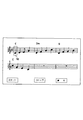
操作されたのが楽譜ナビゲーション用のラジオボタンでない場合には、音符点滅用のラジオボタンが操作されたか否かを判別する(ステップPH7)。このラジオボタンが操作されたときは、オン側の操作であるか又はオフ側の操作であるかを判別する(ステップPH8)。オン側の操作である場合には、フラグBLINKFを1(点滅オン)にセットする(ステップPH9)。オフ側の操作である場合には、BLINKFを0(点滅オフ)にセットする(ステップPH10)。点滅オンに設定された場合には、図30(2)の(a)、(b)に示すように、演奏ガイドの音符の画像51を囲む演奏ガイド用の画像52が点灯と消灯とを交互に繰り返す点滅表示になる。
【0053】
操作されたのが音符点滅用のラジオボタンでない場合には、間違い表示用のラジオボタンが操作されたか否かを判別する(ステップPH11)。このラジオボタンが操作されたときは、オン側の操作であるか又はオフ側の操作であるかを判別する(ステップPH12)。オン側の操作である場合には、フラグMISFを1(間違い表示オン)にセットする(ステップPH13)。オフ側の操作である場合には、MISFを0(間違い表示オフ)にセットする(ステップPH14)。
【0054】
間違い表示オンに設定された場合には、図30(3)の(a)に示すように、演奏ガイドの音符に対応して間違った演奏の音符の画像53を表示する。あるいは、図30(3)の(b)に示すように、間違った演奏の音符の画像54を音符51とは異なる表示色で表示する。あるいはまた、図30(3)の(c)に示すように、間違った演奏の画像55を音符51とは異なる特異な画像で表示する。
【0055】
図29のフローにおいていずれかのフラグをセットした後は、対応するラジオボタンを点灯し、対応しないラジオボタンを消灯する(ステップPH15)。次に、戻りのアイコンスイッチがオンされたか否かを判別する(ステップPH16)。ステップPH2においてラジオボタンが操作されない場合も、ステップPH16に移行して戻りのアイコンスイッチがオンされたか否かを判別する。このアイコンがオンされない場合には、ステップPH2に移行してラジオボタンの操作の有無を判別する。戻りのアイコンがオンされたときは、図27のフローに戻る。
【0056】
図31〜図33は、図27のフローにおけるステップPG6の楽譜表示処理のフローである。図31のフローにおいて、楽譜データエリアのデータに基づき楽譜を表示する(ステップPJ1)。次に、フラグGNABFが1(楽譜ナビオン)であるか否かを判別し(ステップPJ2)、このフラグが1である場合には、音符を指定するポインタnを0(楽譜の先頭の音符)にセットする(ステップPJ3)。次に、WAKU(n)の内容に基づき枠を表示する(ステップPJ4)。この結果、図34に示すように、複数の音符、コード記号等からなる楽譜が表示されるとともに、先頭の音符を囲む枠画像(演奏ガイド用の画像)52が表示される。また、楽譜表示の下側には、「スタート」、「ストップ」、及び「戻り」のアイコンスイッチが表示される。
【0057】
ステップPJ4の後、又は、ステップPJ2においてGNABFが0(楽譜ナビオフ)の場合には枠画像52を表示することなく、アイコンスイッチがオンされたか否かを判別する(ステップPJ5)。いずれかのアイコンスイッチがオンされた場合には、そのアイコンに応じた処理を行う。
スタートのアイコンスイッチがオンされたか否かを判別し(ステップPJ6)、このアイコンがオンされたときは、伴奏情報データエリアにデータがあるか否かを判別する(ステップPJ7)。データがある場合には、そのデータを楽器に転送する(ステップPJ8)。
また、パターン情報データエリアにデータがあるか否かを判別し(ステップPJ9)、データがある場合には、そのデータを楽器に転送する(ステップPJ10)。そして、スタートフラグSTFを1(再生実行)にセットする(ステップPJ11)。
【0058】
ステップPJ6において、スタートのアイコンがオンでない場合には、ストップのアイコンスイッチがオンされたか否かを判別し(ステップPJ12)、このアイコンがオンされたときは、全ての音を消音し(ステップPJ13)、枠画像の表示をクリアする(ステップPJ14)。また、STFを0(再生停止)にセットする(ステップPJ15)。
【0059】
ステップPJ11においてSTFに1をセットした後は、図32のフローにおいて、アドレスレジスタADにMIDIデータエリアのスタートアドレスをセットする(ステップPJ16)。次に、レッスンモードを示すレジスタSTATUSに1をセットし(ステップPJ17)、タイムレジスタSTに現在時間をセットする(ステップPJ18)。さらに、タイムレジスタTに0をセットする(ステップPJ19)。
STATUSの値は押鍵状態によって設定され、1〜3のいずれかの値となる。この値が1の場合には、演奏ガイドの楽音の発音開始タイミングと押鍵タイミングとが合っている状態である。この値が2の場合には、演奏ガイドの楽音の発音開始タイミングに押鍵タイミングが遅れている状態である。この値が3の場合には、演奏ガイドの楽音の発音開始タイミングよりも押鍵タイミングが早い状態である。
【0060】
次に、MEM[AD]のデータがイベントデータであるかタイムデータであるかを判別する(ステップPJ20)。すなわち、曲の最初のデータがイベントデータであるか又はタイムデータであるかを判別する。データがイベントデータである場合には、レジスタΔTに最小時間をセットし(ステップPJ21)、ADをデクリメントする(ステップPJ22)。MEM[AD]のデータがタイムデータである場合には、そのタイムデータMEM[AD]をΔTにセットする(ステップPJ23)。したがって、図30(1)の画面でスタートのアイコンがオンされた瞬間にいきなり再生開始にならず、ΔTにセットされたタイムデータの時間経過後に再生が開始する。
【0061】
ステップPJ22又はステップPJ23の後は、Tの値にΔTの値を加算する(ステップPJ24)。次に、ガイド処理(ステップPJ25)、MIDI IN処理(ステップPJ26)、MIDI OUT処理(ステップPJ27)、楽譜ナビ処理(ステップPJ28)を実行して、図31のステップPJ5に移行する。ステップPJ5においてアイコンスイッチがオンでない場合には、図32のステップPJ25に移行する。
【0062】
図31のステップPJ12において、ストップのアイコンスイッチがオンでない場合には、図33のフローにおいて、戻りのアイコンスイッチがオンされたか否かを判別する(ステップPJ29)。このアイコンがオンされたときは、全ての音の消音処理を行い(ステップPJ30)、STFを0(再生停止)にセットする(ステップPJ31)。そして、図27のフローに戻る。
【0063】
図35〜図38は、図32のフローにおけるステップPJ25のガイド処理のフローである。図35のフローにおいて、STFが1(再生実行)であるか否かを判別し(ステップPK1)、このフラグが1である場合には、現在時刻がST+Tのタイムデータに達したか否かを判別する(ステップPK2)。このタイムデータに達している場合には、ADのアドレスをインクリメントする(ステップPK3)。そして、ADのアドレスがエンドアドレスでないか否かを判別する(ステップPK4)。
【0064】
エンドアドレスでない場合には、MEM[AD]のデータがタイムデータであるか否かを判別する(ステップPK5)。タイムデータである場合には、STATUSの値が3であるか否かを判別する(ステップPK6)。この値が3である場合には、早送りをするためΔTに最小時間をセットする(ステップPK7)。この値が3でなく1又は2である場合には、MEM[AD]をΔTにセットする(ステップPK8)。ΔTにタイムデータをセットした後は、そのΔTのタイムデータをTのタイムデータに加算する(ステップPK9)。そして図32のフローに戻る。
ステップPK4においてADのアドレスがエンドアドレスである場合には、STFに0(再生停止)をセットして(ステップPK10)、図32のフローに戻る。ステップPK1においてSTFが0である場合、又は、ステップPK2において現在時刻がST+Tのタイムデータに達していない場合には、直ちに図32のフローに戻る。
【0065】
ステップPK5において、MEM[AD]のデータがタイムデータでない場合には、図36のフローにおいて、MEM[AD]のデータはイベントデータであるか否かを判別する(ステップPK11)。イベントデータである場合には、チャンネルデータがガイドチャンネルであるか否かを判別する(ステップPK12)。ガイドチャンネルである場合には、さらにイベントデータがノートイベント又はコードイベントであるか否かを判別する(ステップPK13)。ノートイベント又はコードイベントである場合には、ADのアドレスをインクリメントして、ベロシティデータをレジスタVELにセットする(ステップPK14)。そして、VELの値が0でないか否かを判別する(ステップPK15)。この値が0でない場合には、MIDIデータのノート又はコードをレジスタNOTEにセットする(ステップPK16)。
【0066】
次に、ポインタnを0にセットして(ステップPK17)、nの値をインクリメントしながらMIDI OUTバッファ(n)を検索する。すなわち、MIDI OUTバッファ(n)が空きであるか否かを判別し(ステップPK18)、空きでない場合にはnの値をインクリメントする(ステップPK19)。このときnが所定数を超えたか否かを判別し(ステップPK20)、超えていない場合には、ステップPK18に移行してMIDI OUTバッファ(n)を検索する。MIDI OUTバッファ(n)が空きである場合には、MIDI OUTバッファ(n)のイベントエリアにMIDIデータをストアする(ステップPK21)。次に、現在時刻をレジスタWTIMEにセットし(ステップPK22)、MIDI OUTバッファ(n)のタイムエリアにWTIMEのデータをストアする(ステップPK23)。
【0067】
データをストアした後、又はステップPK20においてnが所定数を超えたときは、図37のフローにおいて、STATUSの値が3であるか否かを判別する(ステップPK24)。STATUSの値が3である場合には、STATUSの値を1に変更する(ステップPK25)。そして、チャンネルセットCHSET及びボリュームVOLUMEの値に基づきMIDIデータを作成する(ステップPK26)。
【0068】
図36のフローにおけるステップPK13において、イベントがノートイベント及びコードイベントのいずれでもない場合には、図37のフローにおいて、そのイベントがボリュームイベントであるか否かを判別する(ステップPK27)。ボリュームイベントである場合には、ADのアドレスをインクリメントして、ボリュームの値をレジスタVOLUMEに取り込む(ステップPK28)。次に、STATUSの値が3であるか否かを判別する(ステップPK29)。この値が3である場合には、早送り時の音を消すためにMIDIデータのボリュームの値を最小の値に変更する(ステップPK30)。
【0069】
ボリューム値を最小に変更した後、若しくはステップPK26においてMIDIデータを作成した後、又は、図36のステップPK12においてチャンネルデータがガイドチャンネルでない場合、若しくはステップPK15においてVELの値が0である場合には、図37のステップPK31に移行して、ポインタnを0にセットする。そして、nの値をインクリメントしながらMIDI OUTバッファ(n)を検索する。
【0070】
すなわち、MIDI OUTバッファ(n)が空きであるか否かを判別し(ステップPK32)、空きでない場合にはnの値をインクリメントする(ステップPK33)。このときnが所定数を超えたか否かを判別し(ステップPK34)、超えていない場合には、ステップPK32に移行してMIDI OUTバッファ(n)を検索する。MIDI OUTバッファ(n)が空きである場合には、MIDI OUTバッファ(n)のイベントエリアにMIDIデータをストアする(ステップPK35)。次に、現在時刻をレジスタWTIMEにセットし(ステップPK36)、MIDI OUTバッファ(n)のタイムエリアにWTIMEのデータをストアする(ステップPK37)。
【0071】
データをストアした後、若しくはステップPK34においてnが所定数を超えた場合、又は、図36のステップPK11においてMEM[AD]がイベントデータでない場合には、図35のステップPK3に移行してADをインクリメントする。
【0072】
図37のステップPK24においてSTATUSの値が3でない場合、すなわちこの値が1である場合には、図38のフローにおいて、STATUSの値を2に変更する(ステップPK38)。次に、ポインタnを0にセットして(ステップPK39)、nの値をインクリメントしながらMIDI OUTバッファ(n)を検索する。
すなわち、MIDI OUTバッファ(n)が空きであるか否かを判別し(ステップPK40)、空きでない場合にはnの値をインクリメントする(ステップPK41)。このときnが所定数を超えたか否かを判別し(ステップPK42)、超えていない場合には、ステップPK40に移行してMIDI OUTバッファ(n)を検索する。
【0073】
MIDI OUTバッファ(n)が空きである場合には、MIDI OUTバッファ(n)のイベントエリアににMIDIデータをストアする(ステップPK43)。次に、現在時刻をレジスタWTIMEにセットし(ステップPK44)、MIDI OUTバッファ(n)のタイムエリアににWTIMEのデータをストアする(ステップPK45)。各エリアにデータをストアした後、又はステップPK42においてnが所定数を超えた後は、図32のフローのステップPJ26に移行する。
【0074】
図39は、ステップPJ26のMIDI IN処理のフローである。まず、フラグSTFが1(再生実行)であるか否かを判別する(ステップPL1)。このフラグが1である場合には、MIDI入力があるか否かを判別する(ステップPL2)。入力がある場合には、そのMIDIデータがガイドチャンネルのデータであるか否かを判別する(ステップPL3)。ガイドチャンネルのデータである場合には、さらにそのMIDIデータがノートオン又はコードのイベントであるか否かを判別する(ステップPL4)。ノートオン又はコードのイベントである場合には、次のステップPL5に移行する。上記条件を1つでも満たさない場合には、直ちにこのフローを終了する。
【0075】
ステップPL5においては、MIDIデータのノート又はコードをレジスタKEYにセットする。次に、KEYのデータとNOTEのデータとが一致しているか否かを判別する(ステップPL6)。すなわち、演奏ガイド用として楽器に送信した音高データと、楽器から受信した演奏結果の鍵番号データとが一致しているか否かを判別する。データが一致している場合には、フラグOKFを1(押鍵正解)にセットする(ステップPL7)。次に、現在時刻がST+Tのタイムデータに達していないかを判別する(ステップPL8)。
【0076】
現在時刻がそのタイムデータに達していない場合には、早送りをする必要があるので、STATUSの値を3にセットする(ステップPL9)。ステップPL8において、現在時刻がST+Tのタイムデータに達している場合には、STATUSの値を1にセットし(ステップPL10)、現在時刻からST+Tのタイムデータを減算した値をレジスタSにセットする(ステップPL11)。そして、STのタイムデータにSのタイムデータを加算して更新する(ステップPL12)。すなわち、押鍵の遅れによる時間差を補正する。
【0077】
ステップPL6において、KEYのデータとNOTEのデータとが一致しない場合には、フラグNOFに1をセットする(ステップPL13)。フラグをセットした後、又は、ステップPL9においてSTATUSの値をセットした後、若しくはステップPL12においてSTのタイムデータを更新した後は、図32のステップPJ27に移行する。
【0078】
図40は、ステップPJ27のMIDI OUT処理のフローである。まず、ポインタnを0にセットして(ステップPM1)、nの値をインクリメントしながら以下のループ処理を実行する。MIDI OUTバッファ(n)が空きでないか否かを判別し(ステップPM2)、空きでなくデータがある場合には、MIDI OUTバッファ(n)からMIDIデータとWTIMEのデータを読み出す(ステップPM3)。
【0079】
次に、その読み出したMIDIデータのチャンネルがCHSETのチャンネルと異なっているかを判別する(ステップPM4)。チャンネルが異なっている場合には、現在時刻からWTIMEのタイムデータを減算した値をレジスタDにセットする(ステップPM5)。そして、Dの値が所定時間に達しているか否かを判別する(ステップPM6)。所定時間に達している場合、又はステップPM4においてチャンネルが同じである場合には、ステップPM3において読み出したMIDIデータを楽器に出力する(ステップPM7)。そしてMIDI OUTバッファ(n)をクリアする(ステップPM8)。
【0080】
この後、nの値をインクリメントする(ステップPM9)。ステップPM2においてMIDI OUTバッファ(n)が空きである場合、又はステップPM6においてDの値が所定時間に満たない場合にも、ステップPM9に移行してnの値をインクリメントする。次に、インクリメントしたnの値が所定数を超えたか否かを判別する(ステップPM10)。超えていない場合には、ステップPM2に移行してステップPM10までのループ処理を繰り返す。nの値が所定数を超えたときは、図32のステップPJ28に移行する。
【0081】
図41及び図42は、ステップPJ28の楽譜ナビ処理のフローである。まず、フラグSTFが1(再生実行)であるか否かを判別する(ステップPN1)。このフラグが0である場合には直ちにこのフローを終了するが、このフラグが1である場合には、フラグMISFが1(間違い表示)であるか否かを判別する(ステップPN2)。このフラグが1である場合にはさらに、NOFが1(押鍵誤り)であるか否かを判別する(ステップPN3)。
【0082】
このフラグが1である場合には、演奏ガイドの枠画像であるWAKU(n)の座標とKEYの内容に基づき、KEYの音符に対応するオブジェクトを表示する(ステップPN4)。すなわち、図30(3)の(c)に示すような特異な画像55を表示する。次に、NOFを0にリセットして(ステップPN5)、このフローを終了して図31のステップPJ5に移行する。
【0083】
図41のステップPN2においてMISFが0である場合、又はステップPN3においてNOFが0である場合には、フラグOKFが1(押鍵正解)であるか否かを判別する(ステップPN6)。このフラグが1である場合には、WAKU(n)に対応する演奏ガイドの枠画像の表示を消去するとともに、オブジェクトが表示されていればその画像も消去する(ステップPN7)。次に、nの値をインクリメントする(ステップPN8)。そして、インクリメントしたnの値が最大数以下であるか否かを判別する(ステップPN9)。この値が最大数を超えている場合には、このフローを終了して図31のステップPJ5に移行する。
【0084】
nの値が最大数以下である場合には、図42のフローにおいて、WAKU(n)に対応する枠画像を表示する(ステップPN10)。次に、ポインタQに0をセットし(ステップPN11)、OKFを0にリセットする(ステップPN12)。このリセットの後、又は図41のステップPN6においてOKFが0である場合には、フラグBLINKFが1(点滅表示)であるか否かを判別する(ステップPN13)。このフラグが0である場合には直ちにこのフローを終了するが、このフラグが1である場合には、Qの値をインクリメントする(ステップPN14)。そして、Qの値が所定値を超えたか否かを判別する(ステップPN15)。
【0085】
この値が所定値を超えたときは、枠画像の表示又は消去を指定するフラグBFを反転し(ステップPN16)、Qの値を0にセットする(ステップPN17)。このセットの後、又はステップPN15においてQの値が所定値を超えない場合には、ステップPN18においてBFが1であるか否かを判別する。BFが1である場合には、WAKU(n)の画像を表示する(ステップPN19)。BFが0である場合には、WAKU(n)の画像を消去する(ステップPN20)。枠画像の表示又は消去の後は、図31のステップPJ5に移行する。すなわち、演奏ガイド用の画像である枠画像が所定値のインターバルで点滅表示される。
【0086】
図43は、図2に示した楽器のCPU11のメモリエリアMEMを示している。MEMにはユーザーエリア(RAMエリア)と固定エリア(ROMエリア)があり、複数種類の伴奏情報のデータを格納するための複数のエリアMEM(0)、MEM(1)、…、MEM(N)がある。各エリアMEM( )には、イベントデータ及びタイムデータが交互に格納される。
【0087】
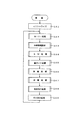
次に、楽器の動作についてCPU11のフローチャートに基づいて説明する。図44は楽器のメインフローである。所定のイニシャライズ処理(ステップGA1)の後、MIDI処理(ステップGA2)、伴奏処理(ステップGA3)、スイッチ処理(ステップGA4)、鍵ガイド処理(ステップGA5)、押鍵処理(ステップGA6)、伴奏処理(ステップGA7)、発音指示処理(ステップGA8)、その他の処理(ステップGA9)、を繰り返し実行する。
【0088】
図45は、図44のフローにおけるMIDI処理のフローである。この処理ではMIDI IN処理(ステップGB1)、MIDI OUT処理(ステップGB2)を実行する。
MIDI IN処理では、図46に示すように、MIDI INがあるか否かを判別する(ステップGC1)。MIDI INがない場合には直ちにこのフローを終了するが、MIDI INがあったときは、ポインタnに0をセットし(ステップGC2)、nをインクリメントしながらMIDI INバッファ(n)が空きであるか否かを判別する(ステップGC3)。
【0089】
MIDI INバッファ(n)が空きでない場合には、nの値をインクリメントする(ステップGC4)。このときnの値が所定数を超えたか否かを判別する(ステップGC5)。所定数以内である場合には、ステップGC3に移行して、MIDI INバッファ(n)が空きであるか否かを判別する。空きである場合には、MIDI INバッファ(n)のエリアにMIDIデータをストアする(ステップGC6)。そして、ステップGC1に移行してMIDI INの有無を判別する。ステップGC5においてnの値が所定数を超えたときは、図45のフローに戻り、ステップGB2のMIDI OUT処理に移行する。
【0090】
MIDI OUT処理では、図47に示すように、ポインタnに0をセットし(ステップGD1)、nの値をインクリメントしながら以下のループ処理を実行する。すなわち、MIDI OUTバッファ(n)が空きでないか否かを判別し(ステップGD2)、空きでなくデータがある場合には、MIDI OUTバッファ(n)からMIDIデータを読み出してパソコンに出力する(ステップGD3)。そしてMIDI OUTバッファ(n)をクリアする(ステップGD4)。この後、nの値をインクリメントする(ステップGD5)。ステップGD2においてMIDI OUTバッファ(n)が空きである場合にも、ステップGD5に移行してnの値をインクリメントする。次に、インクリメントしたnの値が所定数を超えたか否かを判別する(ステップGD6)。超えていない場合には、ステップGD2に移行してステップGD6までのループ処理を繰り返す。nの値が所定数を超えたときは、図44のメインフローに戻り、ステップGA3に移行する。
【0091】
図48は、メインフローにおけるステップGA3の伴奏情報設定処理のフローである。この処理では、ポインタnに0をセットし(ステップGE1)、nの値をインクリメントしながら以下のループ処理を実行する。すなわち、MIDI INバッファ(n)のデータが伴奏情報であるか否かを判別し(ステップGE2)、伴奏情報である場合には、その伴奏情報に基づき楽器設定を行う(ステップGE3)。ステップGE2においてMIDI INバッファ(n)のデータが伴奏パターンである場合には、楽器のパターン作成エリアに転送する(ステップGE5)。この転送の後、又はステップGE3における楽器設定の後は、MIDIOUTバッファ(n)をクリアする(ステップGE6)。この後、nの値をインクリメントする(ステップGE7)。ステップGE4においてMIDI INバッファ(n)のデータが伴奏パターンでない場合にも、ステップGE7に移行してnの値をインクリメントする。次に、インクリメントしたnの値が所定数を超えたか否かを判別する(ステップGE8)。超えていない場合には、ステップGE2に移行してステップGE8までのループ処理を繰り返す。nの値が所定数を超えたときは、図44のメインフローに戻り、ステップGA4に移行する。
【0092】
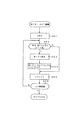
図49は、メインフローにおけるステップGA4のスイッチ処理のフローである。まず、伴奏パターンを選択するSELスイッチが操作されたか否かを判別する(ステップGF1)。操作されたときは、選択された伴奏パターンの番号をレジスタBANSOにセットする(ステップGF2)。このセットの後、又はステップGF1においてSELスイッチが操作されない場合には、スタートスイッチがオンされたか否かを判別する(ステップGF3)。このスイッチがオンされない場合には、直ちにこのフローを終了する。
【0093】
このスイッチがオンされたときは、スタートフラグSTFを反転する(ステップGF4)。そして、STFが1(伴奏演奏実行)であるか否かを判別し(ステップGF5)、このフラグが1である場合には、BANSOの番号に対応する伴奏パターンエリアのスタートアドレスをアドレスレジスタADにセットする(ステップGF6)。次に、初期タイムのデータをタイムレジスタTにセットし(ステップGF7)、タイマインタラプトを禁止解除にする(ステップGF8)。
ステップGF5において、STFが0(伴奏演奏停止)である場合には、消音処理をして(ステップGF9)、タイマインタラプトを禁止する(ステップGF10)。ステップGF8におけるタイマインタラプト禁止解除の後、又はステップGF10におけるタイマインタラプト禁止の後は、図44のメインフローに戻り、ステップGA5に移行する。
【0094】
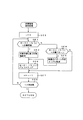
図50は、メインフローにおけるステップGA5の鍵ガイド処理のフローである。この処理では、ポインタnに0をセットし(ステップGK1)、nの値をインクリメントしながら以下のループ処理を実行する。すなわち、MIDI INバッファ(n)が空きでないか否かを判別し(ステップGK2)、空きでない場合には、そのMIDIデータがノート又はコードのイベントであるか否かを判別する(ステップGK3)。ノート又はコードのイベントである場合には、さらにそのイベントのチャンネルアがガイドチャンネルであるか否かを判別する(ステップGK4)。
【0095】
ガイドチャンネルである場合には、MIDIデータのベロシティが0でないか否かを判別する(ステップGK5)。ベロシティが0でない場合には、そのベロシティの値をレジスタVELにセットする(ステップGK6)。次に、VELの値にVSETの値を乗算して、その乗算値に1を加算しその値をVELの値として更新する(ステップGK7)。VSETの値はユーザーによって所望の値に設定することができる。したがって、この値を0に設定することも考えられる。この場合には、上記演算の結果が0になりノートオフになるので、この状態を回避するため1を加算する。VELの更新の後、MIDIデータのベロシティをVELの値に変更する(ステップGK8)。また、MIDIデータのノートに対応する鍵内のLEDを点灯する(ステップGK9)。
【0096】
次に、nの値をインクリメントする(ステップGK10)。そして、インクリメントしたnの値が所定数を超えたか否かを判別する(ステップGK11)。超えていない場合には、ステップGK2に移行してステップGK11までのループ処理を繰り返す。ステップGK5において、MIDIデータのベロシティが0である場合には、MIDIデータのノートに対応するLEDを消灯する(ステップGK12)。次に、nの値をインクリメントする(ステップGK10)。そして、インクリメントしたnの値が所定数を超えたか否かを判別する(ステップGK11)。超えていない場合には、ステップGK2に移行してステップGK11までのループ処理を繰り返す。nの値が所定数を超えたときは、図44のメインフローに戻り、ステップGA6に移行する。
【0097】
図51は、メインフローにおけるステップGA6の押鍵処理のフローである。この処理では最初に鍵盤を走査し(ステップGG1)、鍵変化があるか否かを判別する(ステップGG2)。鍵変化がオンすなわち押鍵である場合には、その鍵のチャンネル、ノート、及びベロシティでMIDIデータを作成する(ステップGG3)。一方、鍵変化がオフすなわち離鍵である場合には、その鍵のチャンネル、ノート、及び値が0のベロシティでMIDIデータを作成する(ステップGG4)。
【0098】
次に、ポインタnに0をセットし(ステップGG5)、nの値をインクリメントしながらMIDI OUTバッファ(n)が空きであるか否かを判別する(ステップGD2)。空きでない場合には、nの値をインクリメントする(ステップGG7)。そして、インクリメントしたnの値が所定数を超えたか否かを判別する(ステップGG8)。超えていない場合には、ステップGG2に移行してMIDI OUTバッファ(n)が空きであるか否かを判別する。空きである場合には、MIDI OUTバッファ(n)にMIDIデータをストアする(ステップGG9)。
【0099】
MIDIデータをストアした後、又はステップGG8においてnの値が所定値を超えた場合、若しくはステップGG2において鍵変化がない場合には、鍵盤の走査が終了したか否かを判別する(ステップGG10)。走査が終了していない場合には、ステップGG1に移行して走査を続行する。走査が終了した場合には、MIDI OUTのバッファの内容からコードが成立しているか否かを判別する(ステップGG11)。成立している場合には、コードの根音をレジスタROOTにセットし、コード種をレジスタCODEにセットする(ステップGG12)。根音及びコード種をセットした後、又はコードが成立しない場合には、図44のメインフローに戻り、ステップGA7に移行する。
【0100】
図52は、メインフローにおけるステップGA7の伴奏処理のフローである。まず、スタートフラグSTFが1(伴奏演奏実行)であるか否かを判別し(ステップGH1)、このフラグが1である場合には、タイマレジスタTの値が0であるか否かを判別する(ステップGH2)。STFが0(伴奏演奏停止)である場合、又はTの値が0でない場合には、直ちにこのフローを終了する。
【0101】
Tの値が0である場合には、MEM(AD)からMIDIイベントを読み出す(ステップGH3)。そしてそのMIDIイベントがコードトデータであるか否かを判別する(ステップGH4)。コードデータである場合には、CODEのコード種及びROOTの根音で複数の音高データに変換する(ステップGH5)。音高変換の後、又はMIDIイベントがコードデータでなくノートデータである場合には、ポインタnに0をセットして(ステップGH6)、nをインクリメントしながら、MIDI OUTバッファ(n)が空きであるか否かを判別する(ステップGH7)。空きでない場合には、nの値をインクリメントする(ステップGH8)。そして、インクリメントしたnの値が所定数を超えたか否かを判別する(ステップGH9)。超えていない場合には、ステップGH7に移行してMIDI OUTバッファ(n)が空きであるか否かを判別する。空きである場合には、MIDI OUTバッファ(n)にMIDIデータをストアする(ステップGH10)。
【0102】
MIDIデータをストアした後、又はステップGH9においてnの値が所定値を超えた場合には、ADのアドレスをインクリメントする(ステップGH11)。そして、インクリメントしたADのアドレスがエンドアドレスを超えたか否かを判別する(ステップGH12)。超えた場合には、ADのアドレスをスタートアドレスに変更する(ステップGH13)。ADのアドレスがエンドアドレスを超えない場合、又はスタートアドレスに変更した場合には、MEM(AD)のデータがタイムデータであるか否かを判別する(ステップGH14)。タイムデータである場合には、MEM(AD)のタイムデータをTにセットして(ステップGH15)、ステップGH11に移行してステップGH14までのループを繰り返す。MEM(AD)がタイムデータでない場合には、図44のメインフローに戻り、ステップGA8に移行する。
【0103】
図53は、メインフローにおける発音指示処理のフローである。まず、ポインタnに0をセットして(ステップGJ1)、nをインクリメントしながら以下のループ処理を繰り返す。すなわち、MIDI INバッファ(n)が空きでないか否かを判別し(ステップGJ2)、空きでない場合には、そのMIDIデータを音源へ送付する(ステップGJ3)。そしてMIDI INバッファ(n)をクリアする(ステップGJ4)。
【0104】
バッファをクリアした後、又はステップGJ2においてMIDI INバッファ(n)が空きである場合には、MIDI OUTバッファ(n)が空きでないか否かを判別し(ステップGJ2)、空きでない場合には、そのMIDIデータを音源へ送付する(ステップGJ6)。そしてMIDI OUTバッファ(n)をクリアする(ステップGJ7)。
バッファをクリアした後、又はステップGJ5においてMIDI OUTバッファ(n)が空きである場合には、nの値をインクリメントする(ステップGJ8)。そしてnの値が所定数を超えたか否かを判別する(ステップGJ9)。超えていない場合には、ステップGJ2に移行して上記ループ処理を繰り返す。nの値が所定数を超えた場合には、図44のメインフローに戻り、ステップGA9のその他の処理を実行する。
【0105】
このように上記実施形態によれば、各曲ごとにそれぞれ異なる態様でアレンジされた複数の演奏教習用の曲データを格納するサーバシステムである曲データサーバ4にネットワーク3を介して接続し、曲データサーバ4から曲データの配信を受ける場合に、パソコン2及び楽器1で構成されたクライアントシステムの環境情報を送信して、各曲ごとにそれぞれ異なる態様でアレンジされた複数の演奏教習用の曲データの中からクライアントシステムの環境に適合する態様でアレンジされた演奏教習用の曲データの配信を受ける。
したがって、インターネット等の通信手段を介してサーバシステムから配信を受けた曲データに基づいて演奏教習を行う場合に、クライアントシステムに最適な態様でアレンジされた曲データの配信が得られる。
【0106】
この場合において、クライアントシステムは、サーバシステムに曲データを要求する際は、クライアントシステムに収容する楽器1の環境情報をサーバシステムに送信する。
したがって、楽器1の環境(例えば楽器の機種や演奏者であるユーザのスキル)に最適なアレンジの曲データの配信を受けることができる。
【0107】
この場合において、ユーザのスキルについては、図20のフロー及び図21の表示画面に示したように、ユーザ自身が設定する構成にしたが、ユーザが自分の熟練度に対して客観的な評価を下すのは困難な場合もある。そこで、ユーザに実際に演奏させてパソコンが自動的にスキル設定を行うようにしてもよい。例えば、代表曲について所定数のフレーズごとにアレンジのレベルを変えて演奏させ、その演奏結果でスキル設定を行う構成にしてもよい。この場合、自動スキル設定を行うか又はユーザ自身が設定するかはユーザが選択する。
【0108】
なお、上記実施形態においては、パソコン2によって曲データサーバ4から楽譜の画像データと楽音のMIDIデータを受信する構成にしたが、楽器内にMODEM及び表示部を収容し、ネットワークを介して直接曲データサーバにアクセスして、曲データ及びその曲にふさわしい伴奏パターンデータの送信を要求する構成にしてもよい。
【0109】
また、上記実施形態においては、パソコン2のROM33に格納されている演奏教習処理のプログラムによって、演奏教習処理を実行する構成にしたが、このプログラムをパソコンや楽器によって読み取り可能な汎用の記憶媒体、例えば、フロッピーディスク、CD、MDその他に記憶して、上記フローチャートに示した演奏教習処理をパソコンや楽器に実行させる構成にしてもよい。この場合には、記憶媒体の発明を提供する。
あるいは、演奏教習処理のプログラム自体も曲データサーバ4からネットワーク3を介してダウンロードする構成にしてもよい。
【0110】
【発明の効果】
本発明によれば、曲毎に複数の演奏教習用データを格納するサーバシステムに通信手段を介して接続したクライアントシステムが、そのサーバシステムから演奏教習データの配信を受ける際に、クライアントシステムに入力された演奏技術のレベルを示す情報を送信して、それらの情報に適合する演奏教習データの配信を受け、演奏ガイド及び演奏判定の少なくともいずれか一方を含む演奏教習を行う。
したがって、インターネット等の通信手段を介して配信を受けた演奏教習データに基づいて演奏教習を行う場合に、クライアントシステムに入力された演奏技術のレベルに最適な演奏教習が行える。
【図面の簡単な説明】
【図1】本発明の装置のシステム構成を示す図。
【図2】図1における楽器のシステム構成を示すブロック図。
【図3】図1におけるパソコンのシステム構成を示すブロック図。
【図4】図1における曲データサーバのメモリエリアを示す図。
【図5】図1における曲データサーバのメモリエリアを示す図。
【図6】図1における曲データサーバのメモリエリアを示す図。
【図7】図1における曲データサーバのメモリエリアを示す図。
【図8】図1における曲データサーバのメモリエリアを示す図。
【図9】図1における曲データサーバのメインフローチャート。
【図10】図9におけるファイル作成処理のフローチャート。
【図11】図10に続くファイル作成処理のフローチャート。
【図12】図11に続くファイル作成処理のフローチャート。
【図13】図1におけるパソコンのメモリエリアを示す図。
【図14】図3におけるパソコンのCPUのメインフローチャート。
【図15】メニュー画面を示す図。
【図16】図14におけるダウンロード処理のフローチャート。
【図17】ダウンロード画面を示す図。
【図18】図16における曲選択処理のフローチャート。
【図19】曲リストの画面を示す図。
【図20】図16における環境設定処理のフローチャート。
【図21】環境設定の画面を示す図。
【図22】図16における送受信処理のフローチャート。
【図23】図22に続く送受信処理のフローチャート。
【図24】曲ダウンロード中の画面を示す図。
【図25】図22におけるクオンタイズ処理のフローチャート。
【図26】図25に続くクオンタイズ処理のフローチャート。
【図27】図14における再生処理のフローチャート。
【図28】曲再生のメニュー画面を示す図。
【図29】図27における楽譜ナビ設定処理のフローチャート。
【図30】(1)は楽譜ナビ設定の画面を示す図、(2)は演奏ガイド用の画像を点滅表示する例を示す図、(3)は押鍵誤りを表示する複数の例を示す図。
【図31】図27における楽譜表示処理のフローチャート。
【図32】図31に続く楽譜表示処理のフローチャート。
【図33】図31に続く楽譜表示処理のフローチャート。
【図34】楽譜表示の画面を示す図。
【図35】図32におけるガイド処理のフローチャート。
【図36】図35に続くガイド処理のフローチャート。
【図37】図36に続くガイド処理のフローチャート。
【図38】図37に続くガイド処理のフローチャート。
【図39】図32におけるMIDI IN処理のフローチャート。
【図40】図32におけるMIDI OUT処理のフローチャート。
【図41】図32における楽譜ナビ処理のフローチャート。
【図42】図41に続く楽譜ナビ処理のフローチャート。
【図43】図1における楽器のメモリエリアを示す図。
【図44】図2における楽器のCPUのメインフローチャート。
【図45】図44におけるMIDI処理のフローチャート。
【図46】図45におけるMIDI IN処理のフローチャート。
【図47】図45におけるMIDI OUT処理のフローチャート。
【図48】図44における伴奏情報設定処理のフローチャート。
【図49】図44におけるスイッチ処理のフローチャート。
【図50】図44における鍵ガイド処理のフローチャート。
【図51】図44における押鍵処理のフローチャート。
【図52】図44における伴奏処理のフローチャート。
【図53】図44における発音指示処理のフローチャート。
【符号の説明】
1 楽器
2 パソコン
3 ネットワーク
4 曲データサーバ[0001]
BACKGROUND OF THE INVENTION
The present inventionThe performance learning system.
[0002]
[Prior art]
It has been proposed to receive music data via a communication means such as the Internet, download it to a memory such as a RAM, and perform performance learning based on the music data. For example, when performing a performance lesson with a keyboard instrument or the like, the keys corresponding to the pitch data of the song data received by the light emitting element provided below each key are illuminated to perform navigation of the key to be played. It is configured.
[0003]
[Problems to be solved by the invention]
However, in the above-mentioned conventional proposal, even if music data for performance learning is downloaded from the
[0004]
An object of the present invention is to make it possible to obtain optimal music data distribution for a performance device or a player when performing performance learning based on music data distributed via communication means such as the Internet. is there.
[0005]
[Means for Solving the Problems]
The performance learning system according to
The server system is configured to connect the client from any client system connected via the communication unit.Indicates the level of performance skills entered into the systemWhen requested to distribute performance training data for any song along with information,The performance training data corresponding to the level of the performance technique input to the client system from among a plurality of performance training data is distributed as performance training data for the arbitrary music, and the client system is distributed Based on the performance learning data, a performance learning including at least one of a performance guide and performance determination is performed.
[0007]
Claim 1InAccording to the described invention,Multiple performance lessons for each songFrom the server system that stores dataPerformance lessonsClient system when receiving data distributionIn response to the distribution of performance training data suitable for the level of the performance technique input to the performance training, the performance training including at least one of a performance guide and performance determination is performed.
[0008]
DETAILED DESCRIPTION OF THE INVENTION
Embodiments of the present invention will be described below with reference to the drawings.
FIG. 1 shows a system configuration in the present invention. The
[0009]
FIG. 2 is a block diagram showing a configuration of the
[0010]
The
[0011]
The
[0012]
FIG. 3 shows the system configuration of the
[0013]
The
[0014]
The
[0015]
Next, the operation of the system configuration shown in FIG. 1 will be described in detail.
First, the operation of the
4 to 8 are diagrams showing memory area maps in the server. As shown in FIG. 4, the server memory area includes a buffer area, an RGB (color display score) area, a CMD (performance guide command) area, an MID (song data) area, a SET (playback information) area, and a PAT (playback information) area. Accompaniment pattern) area.
[0016]
In the buffer area, together with header data, data of other areas, that is, RGB data, CMD data, MID data, SET data, and PAT data are temporarily stored. The header data stores the total number of files in the buffer area, RGB, CMD, MID, SET, and PAT header data. For example, the header data for RGB includes a file name, a start address, and an end address. The same applies to other header data.
[0017]
FIG. 5 shows the layer structure of the score data in the RGB area. The uppermost layer is composed of score data corresponding to a plurality of (for example, N) songs, RGB (1), RGB (2), RGB (3),... RGB (N). The lower layer of each song, for example, the lower layer of RGB (1) is score data corresponding to a plurality of musical instrument models, RGB (1, 1), RGB (1, 2), RGB (1, 3). ,... Composed of RGB (1, N). Further, a layer for each lower model, for example, a lower layer of RGB (1, 1), score data corresponding to a plurality of skills (user skill levels), RGB (1, 1, 1), RGB (1, 1, 2), RGB (1, 1, 3),..., RGB (1, 1, N). Each skill data, for example, RGB (1, 1, 1) data includes a file name and score data.
[0018]
FIG. 6 shows a layer structure of accompaniment pattern data in the PAT area. The highest layer is composed of accompaniment pattern data corresponding to a plurality of (N) pieces of music, PAT (1), PAT (2), PAT (3),... PAT (N). The lower layer of each song, for example, the lower layer of PAT (1) is accompaniment pattern data corresponding to a plurality of instrument types, PAT (1, 1), PAT (1, 2), PAT (1, 3). ),... PAT (1, N). Further, the layer for each lower model, for example, the lower layer of PAT (1, 1), accompaniment pattern data corresponding to a plurality of skills (user skill levels), PAT (1, 1, 1), PAT (1 , 1, 2), PAT (1, 1, 3),... PAT (1, 1, N). Each skill data, for example, PAT (1, 1, 1) data includes a file name and accompaniment pattern data.
[0019]
As will be described later, the accompaniment pattern data is downloaded to a musical instrument via a personal computer and stored in the user area of the musical instrument. However, some musical instrument models do not have a user area. For example, the model corresponding to PAT (1, 3) in FIG. 6 has no user area. Therefore, the accompaniment pattern data is “none”.
[0020]
FIG. 7 shows a layer structure of drawing command data in the CMD area. The uppermost layer is composed of drawing commands corresponding to a plurality (N) of songs, CMD (1), CMD (2), CMD (3),... CMD (N). The lower layer of each song, for example, the lower layer of CMD (1) is a drawing command corresponding to a plurality of instrument models, CMD (1, 1), CMD (1, 2), CMD (1, 3). ... CMD (1, N). Further, a layer for each lower model, for example, a lower layer of CMD (1, 1), draw commands corresponding to a plurality of skills (user skill levels), CMD (1, 1, 1), CMD (1, 1, 2), CMD (1, 1, 3),... CMD (1, 1, N). Each skill data, for example, CMD (1, 1, 1) data includes a file name and a drawing command.
[0021]
The drawing command data is prepared for each of a plurality of notes constituting the score, and as shown in FIG. 8, the drawing command data is composed of a plurality of data composed of WAKU (0), WAKU (1),..., WAKU (N). Has been. Each data includes coordinates (x, y) indicating the display position, size (height and width if the shape is a square), shape (square and circle), color, and outer frame line (width and type). ) Data.
[0022]
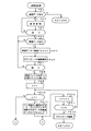
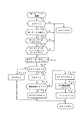
Next, the operation of the song data server will be described with reference to a flowchart. FIG. 9 is a main flow of the music data server. It is determined whether or not there is reception from the personal computer (step SA1), and if there is reception, it is determined whether or not a song number has been received (step SA2). When the song number is received, the received data is set in the register MELODY (step SA3). Then, 1 is set in the melody flag MF (step SA4). If the received data is not a song number in step SA2, it is determined whether the received data is environmental data (step SA5). If it is environmental data, the model data in the environmental data is set in the register, and the skill data in the environmental data is set in the register SKILL (step SA6). Then, 1 is set to the environment flag KF (step SA7).
[0023]
Next, it is determined whether or not both MF and KF are 1 (step SA8). If neither is 1, the process proceeds to step SA1 to determine whether there is received data. If both MF and KF are 1, file creation processing is executed (step SA9). Next, a transmission process for transmitting the created file to the personal computer is executed (step SA10), and both MF and KF are reset to “0” (step SA11). Then, the process proceeds to step SA1 to determine whether there is received data.
[0024]
10 to 12 are flowcharts of the file creation process in step SA9 in the flowchart of FIG. In the flow of FIG. 10, an RGB (MELODY, KISHU, SKILL) file is designated in the RGB area (step SB1). Next, the data of the designated file is stored in the buffer (step SB2). Further, the file name, start address, and end address are written in the header portion (step SB3). In addition, a CMD (MELODY, KISHU, SKILL) file in the CMD area is designated (step SB4). Next, the data of the designated file is stored in the buffer (step SB5). Further, the file name, start address, and end address are written in the header portion (step SB6).
[0025]
Next, in the flow of FIG. 11, a file of MID (MELODY, KISHU, SKILL) in the MID area is designated (step SB7). Next, the data of the designated file is stored in the buffer (step SB8). Further, the file name, start address, and end address are written in the header portion (step SB9). Further, a SET (MELODY, KISHU, SKILL) file in the SET area is designated (step SB10). It is determined whether or not the designated data exists (step SB11). If there is data, the data of the designated file is stored in the buffer (step SB12). Further, the file name, start address, and end address are written in the header portion (step SB13). Of course, when there is no data, data storage and header writing are not performed.
[0026]
Next, in the flow of FIG. 12, a file of PAT (MELODY, KISHU, SKILL) in the PAT area is designated (step SB14). It is determined whether or not the designated data exists (step SB15). If there is data, the data of the designated file is stored in the buffer (step SB16). Further, the file name, start address, and end address are written in the header portion (step SB17). Of course, when there is no data, data storage and header writing are not performed. Thereafter, the number N of files written in the buffer is written in the header (step SA18), and the process returns to the main flow of FIG.
[0027]
FIG. 13 shows a memory area of the
[0028]
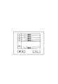
Next, the operation of the personal computer will be described with reference to the flowchart of the
[0029]
When the icon switch is turned on, it is determined whether the download icon switch is turned on or the reproduction icon switch is turned on (step PA4). When the download icon switch is turned on, a download process is executed (step PA5), and when the playback icon switch is turned on, a playback process is executed (step PA6). After the download process or playback process, the process proceeds to step PA2 to display a menu screen.
[0030]
FIG. 16 is a flow of the download process in step PA5 in the flow of FIG. First, the download menu screen shown in FIG. 17 is displayed (step PB1). In other words, “Song List”, “Environment Setting”, “Send”, and “Back” icon switches are displayed. Then, it is determined whether or not the icon switch is turned on (step PB2). When the icon switch is turned on, processing corresponding to the turned on icon switch is performed.
[0031]
It is determined whether or not the music list icon switch is turned on (step PB3), and when it is turned on, a music selection process is executed (step PB4). It is determined whether or not the environment setting icon switch is turned on (step PB5). When this icon is turned on, an environment setting process is executed (step PB6). After performing the song selection process or the environment setting process, the process proceeds to step PB1 to display the menu screen of FIG.
[0032]
If the song list and environment setting icon switches are not turned on, it is determined whether or not the transmission icon switch is turned on (step PB7). If turned on, transmission / reception processing is executed (step PB8). Thereafter, the set contents are cleared (step PB9), and the process returns to the main flow of FIG. When the transmission icon switch is not turned on, it is determined whether or not the return icon switch is turned on (step PB). When the transmission icon switch is turned on, the setting contents are cleared (step PB9), and the process returns to the main flow of FIG. . If the return icon is not turned on, the process proceeds to step PB1.
[0033]
FIG. 18 is a flowchart of the music selection process of step PB4 in the flow of FIG. First, the music list shown in FIG. 19 is displayed (step PC1). In addition to the song list, an “OK” icon switch and a “Return” icon switch are displayed on this screen. Next, it is determined whether or not any song list is turned on (step PC2). When turned on, the song number is set in the register MELODY (step PC3).
[0034]
If the song list is not turned on, it is determined whether or not the icon switch is turned on (step PC4). When turned on, it is determined whether the return icon switch is turned on or the OK icon switch is turned on (step PC5). When the return icon switch is turned on, the music number set in MELODY is cleared (step PC6), and the flow returns to the flow of FIG. When the OK icon switch is turned on, the process returns to the flow of FIG. 16 while keeping the music number set in MELODY.
[0035]
FIG. 20 is a flow of environment setting processing in step PB6 in the flow of FIG. First, the environment setting screen shown in FIG. 21 is displayed (step PD1). This screen has an area for displaying the model name of the instrument and an area for displaying the skill of the performer, and displays a “return” icon switch and an “OK” icon switch. After the environment setting screen is displayed, it is determined whether or not data such as characters is input from the keyboard (step PD2).
[0036]
When there is an input, it is determined whether or not the data is a model name (step PD3). If it is a model name, the model name data is set in the register KISHU (step PD4A). Then, the KISYU data is stored in the transmission buffer (step PD4B). Also, the model name set in KISHU is displayed in the corresponding area of the screen (step PD5). If the input data is not a model name, that is, if the data is a performance level (skill), the performance level data is set in the register SKILL (step PD6A). Then, the SKILL data is stored in the transmission buffer (step PD6B). Also, the performance level set in SKILL is displayed in the corresponding area of the screen (step PD7). After the model name or performance level is displayed, the process proceeds to step PD2 to determine data input.
[0037]
If there is no data input from the keyboard, it is determined whether or not the icon switch is turned on (step PD8). When the icon switch is turned on, it is determined whether it is a return icon switch or an OK icon switch (step PD9). If the return icon switch is turned on, the setting contents are cleared (step PD10), and the flow returns to the flow of FIG. If the OK icon switch is turned on, the process returns to the flow of FIG. 16 while retaining the setting contents.
[0038]
22 and 23 are flowcharts of the transmission / reception process of step PB8 in the flowchart of FIG. In FIG. 22, it is determined whether or not there is transmission data in the transmission buffer (step PE1). If there is transmission data, transmission processing is executed (step PE2). If there is instrument model name data or skill data in the transmission buffer, it is transmitted to the song data server as environment information. And it is discriminate | determined whether transmission was complete | finished (step PE3). If transmission data remains, the transmission process is continued, but when transmission ends, it is determined whether or not there is reception data (step PE4).
If there is received data, the received data is stored in the receiving buffer shown in FIG. 13 (step PE5), and the downloading screen shown in FIG. 24 is displayed (step PE6). And it is discriminate | determined whether reception data was complete | finished (step PE7). If not completed, the process proceeds to step PE4 to determine the presence or absence of received data.
[0039]
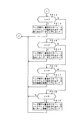
When the reception data is completed, the number of files in the header part in the reception buffer is set in the register N (step PE8). Next, the pointer n is set to 1 (step PE9), and the data in the reception buffer corresponding to n is stored in the corresponding area while incrementing the value of n.
That is, it is determined whether or not n is 1 (step PE10). If n is 1, data specified by the nth start address and end address of the header is stored in the score data area. (Step PE11).
If n is not 1, it is determined whether or not n is 2 in the flow of FIG. 23 (step PE12). If n is 2, the nth start address and end address of the header portion are determined. The data specified by is stored in the CMD data area (step PE13).
[0040]
If n is not 2, it is determined whether or not n is 3 (step PE14). If n is 3, the data specified by the nth start address and end address of the header part is determined. Store in the MIDI data area (step PE15).
If n is not 3, it is determined whether or not n is 4 (step PE16). If n is 4, the data specified by the nth start address and end address of the header part is determined. Store in the accompaniment setting information data area (step PE17).
If n is not 4, it is determined whether or not n is 5 (step PE18). If n is 5, the data specified by the nth start address and end address of the header part is determined. Store in the pattern information data area (step PE19).
[0041]
After the designated data is stored in the corresponding area, the value of n is incremented in step PE20 of FIG. Then, it is determined whether or not the value of n has become larger than the value of N (in this case, N = 5) (step PE21). If the value of n is less than or equal to the value of N, the process proceeds to step PE10. When the value of n becomes larger than the value of N (in this case, n = 6), the quantization process is executed (step PE22), and the process returns to the flow of FIG.
[0042]
25 and 26 are flowcharts of the quantization process. First, the start address of the MIDI data area is set in the address register AD (step PF1). Then, the MIDI data area is searched while incrementing the AD address.
That is, it is determined whether the MIDI (AD) data is a note-on event of a guide channel (a channel for navigating a chord) (step PF2). If the data is not a note-on event of the guide channel, the AD address is incremented (step PF3). It is determined whether or not the incremented AD address is larger than the end address (step PF4). If it is equal to or less than the end address, the process proceeds to step PF2 to determine the content of MIDI (AD) data.
[0043]
If the MIDI (AD) data is a guide channel note-on event, the value of the time register T is reset to 0 (step PF5). Next, the value of the pointer m is set to 1 (step PF6), and the value of the pointer n is set to 0 (step PF7). Then, note data of the note-on event is set in the register NOTE (n) (step PF8). Next, the content of MIDI (AD + m) data is determined (step PF9).
[0044]
If this data is time data, the time data, that is, MIDI (AD + m) data is added to the value of T (step PF10). And it is discriminate | determined whether the value of T is larger than predetermined time (step PF11). The predetermined time is a threshold value for determining whether or not a plurality of note-on events are chords. A plurality of note-on events whose time data is smaller than the threshold value are chord candidates. If the value of T is less than or equal to the predetermined time, the value of m is incremented (step PF12). At this time, it is determined whether or not the address of AD + m is larger than the end address (step PF13). If it is equal to or less than the end address, the process proceeds to step PF9 to determine the content of the MIDI (AD) data.
[0045]
If the MIDI (AD + m) data is an event, it is further determined whether or not the MIDI (AD + m) event is a guide channel note-on event (step PF14). If it is a note-on event of the guide channel, the event is a code candidate that has the possibility of forming a code with the event at the previous address. Therefore, the value of n is incremented (step PF15), and the note data of the event is set to NOTE (n) (step PF16). Next, the process proceeds to step PF12 and the value of m is incremented.
[0046]
In step PF11, as long as the value of T is equal to or less than the predetermined time and the next data is a note-on event of the guide channel, the above loop processing is repeated. If the next data is not a note-on event of the guide channel, for example, if it is control data such as a control change, the process proceeds to step PF12 and the value of m is incremented. In step PF11, when the value of T becomes larger than the predetermined time, it is determined whether or not a chord is established by a plurality of note-on events set in NOTE (0) to NOTE (n) (step PF17). . If the code is not established, the data of NOTE (0) to NOTE (n) is cleared (step PF18), the process proceeds to step PF3, and the AD address is incremented.
[0047]
If the code is established in step PF17, the MIDI (AD) event is changed to code data in the flow of FIG. 26 (step PF19). Next, the note-off event for NOTE (1) to (n) is deleted (step PF20), and the time data is changed (step PF21). That is, since a plurality of note-on events constituting a chord have been changed to one chord data, only one note-off event corresponding to the chord event is left, other note-off events are deleted, and time data is obtained by the deletion. Change (delta time). Also, in response to the coding and note-off event deletion, m is added to the AD address to designate the next address (step PF22). Then, the process proceeds to step PF3 in FIG. 25 to increment the AD address. If the AD address is larger than the end address in step PF4, the quantization process flow is terminated.
[0048]
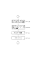
FIG. 27 is a flowchart of the reproduction process of step PA6 in the main flow of FIG. First, the reproduction screen shown in FIG. 28 is displayed (step PG1). On this screen, “music score navigation setting”, “music score display”, and “return” icon switches are displayed. Next, it is determined whether or not the icon switch is turned on (step PG2). When any one of the icon switches is turned on, processing corresponding to the icon is performed.
[0049]
It is determined whether or not the musical score navigation setting icon switch is turned on (step PG3). When this icon is turned on, musical score navigation setting processing is executed (step PG4). Alternatively, it is determined whether or not the musical score display icon switch is turned on (step PG5), and when this icon is turned on, musical score display processing is executed (step PG6). After the musical score navigation setting process or the musical score display process, the process proceeds to step PG1 to display a reproduction screen. If neither the musical score navigation setting nor the musical score display icon switch is turned on, it is determined whether or not the return icon switch is turned on (step PG7), and when this icon is turned on, the main flow of FIG. Return.
[0050]
FIG. 29 is a flowchart of the musical score navigation setting process of step PG4 in the flowchart of FIG. First, the musical score navigation setting screen shown in FIG. 30 (1) is displayed (step PH1). This screen includes a radio button for musical score navigation for setting whether or not to perform musical score navigation, a radio button for blinking musical notes for setting whether or not to blink an image indicating the next note, and a performance result. An error display radio button for setting whether or not to display an error and a return icon switch are displayed.
[0051]
And it is discriminate | determined whether one of the radio buttons was operated (step PH2). When any one of the radio buttons is operated, processing corresponding to the operated radio button is performed. That is, it is determined whether or not the radio button for musical score navigation is operated (step PH3), and when this radio button is operated, it is determined whether the operation is an on-side operation or an off-side operation. (Step PH4). If the operation is on-side, the flag GNABF is set to 1 (music score navigation on) (step PH5). If the operation is on the off side, GNABF is set to 0 (musical score navigation off) (step PH6).
[0052]
If the radio button for musical score navigation is not operated, it is determined whether or not the radio button for flashing notes is operated (step PH7). When this radio button is operated, it is determined whether the operation is an on-side operation or an off-side operation (step PH8). If the operation is on-side, the flag BLINKF is set to 1 (flashing on) (step PH9). If the operation is on the off side, BLINKF is set to 0 (flashing off) (step PH10). When the flashing is set to on, as shown in (a) and (b) of FIG. 30 (2), the
[0053]
If it is not a radio button for blinking notes, it is determined whether or not a radio button for error display has been operated (step PH11). When this radio button is operated, it is determined whether the operation is an on-side operation or an off-side operation (step PH12). If the operation is on-side, the flag MISF is set to 1 (error display on) (step PH13). If the operation is on the off side, the MISF is set to 0 (error display off) (step PH14).
[0054]
When the error display is set to ON, as shown in (a) of FIG. 30 (3), an image 53 of a wrong performance note is displayed corresponding to the note of the performance guide. Alternatively, as shown in (b) of FIG. 30 (3), the image 54 of the wrong performance note is displayed in a display color different from the
[0055]
After any flag is set in the flow of FIG. 29, the corresponding radio button is turned on and the non-corresponding radio button is turned off (step PH15). Next, it is determined whether or not the return icon switch is turned on (step PH16). Even when the radio button is not operated in step PH2, the process proceeds to step PH16 to determine whether or not the return icon switch is turned on. If this icon is not turned on, the process proceeds to step PH2 to determine whether or not the radio button is operated. When the return icon is turned on, the flow returns to the flow of FIG.
[0056]
31 to 33 are flowcharts of the score display process of step PG6 in the flowchart of FIG. In the flow of FIG. 31, a score is displayed based on the data in the score data area (step PJ1). Next, it is determined whether or not the flag GNABF is 1 (musical score navigation on) (step PJ2). If this flag is 1, the pointer n for designating a note is set to 0 (the first musical note of the musical score). Set (step PJ3). Next, a frame is displayed based on the contents of WAKU (n) (step PJ4). As a result, as shown in FIG. 34, a score composed of a plurality of notes, chord symbols and the like is displayed and a frame image (performance guide image) 52 surrounding the first note is displayed. In addition, “start”, “stop”, and “return” icon switches are displayed below the score display.
[0057]
After step PJ4 or when GNABF is 0 (musical score navigation off) in step PJ2, it is determined whether or not the icon switch is turned on without displaying the frame image 52 (step PJ5). When any icon switch is turned on, processing corresponding to the icon is performed.
It is determined whether or not the start icon switch is turned on (step PJ6). When this icon is turned on, it is determined whether or not there is data in the accompaniment information data area (step PJ7). If there is data, the data is transferred to the instrument (step PJ8).
Further, it is determined whether or not there is data in the pattern information data area (step PJ9). If there is data, the data is transferred to the musical instrument (step PJ10). Then, the start flag STF is set to 1 (playback execution) (step PJ11).
[0058]
If the start icon is not turned on in step PJ6, it is determined whether or not the stop icon switch is turned on (step PJ12). If this icon is turned on, all sounds are muted (step PJ13). ), The display of the frame image is cleared (step PJ14). Further, STF is set to 0 (reproduction stop) (step PJ15).
[0059]
After 1 is set in STF in step PJ11, the start address of the MIDI data area is set in address register AD in the flow of FIG. 32 (step PJ16). Next, 1 is set in the register STATUS indicating the lesson mode (step PJ17), and the current time is set in the time register ST (step PJ18). Further, 0 is set in the time register T (step PJ19).
The value of STATUS is set according to the key depression state, and is one of 1 to 3. When this value is 1, the sound generation start timing of the musical tone of the performance guide matches the key pressing timing. When this value is 2, the key pressing timing is delayed with respect to the tone generation start timing of the musical tone of the performance guide. When this value is 3, the key pressing timing is earlier than the tone generation start timing of the musical tone of the performance guide.
[0060]
Next, it is determined whether the data of MEM [AD] is event data or time data (step PJ20). That is, it is determined whether the first data of the music is event data or time data. If the data is event data, the minimum time is set in the register ΔT (step PJ21), and AD is decremented (step PJ22). If the MEM [AD] data is time data, the time data MEM [AD] is set to ΔT (step PJ23). Therefore, the playback does not start suddenly at the moment when the start icon is turned on on the screen of FIG. 30 (1), and the playback starts after the time data set in ΔT has elapsed.
[0061]
After step PJ22 or step PJ23, the value of ΔT is added to the value of T (step PJ24). Next, guide processing (step PJ25), MIDI IN processing (step PJ26), MIDI OUT processing (step PJ27), and musical score navigation processing (step PJ28) are executed, and the process proceeds to step PJ5 in FIG. If the icon switch is not on in step PJ5, the process proceeds to step PJ25 in FIG.
[0062]
If the stop icon switch is not on in step PJ12 of FIG. 31, it is determined whether or not the return icon switch is turned on in the flow of FIG. 33 (step PJ29). When this icon is turned on, all sounds are muted (step PJ30), and STF is set to 0 (reproduction stop) (step PJ31). And it returns to the flow of FIG.
[0063]
35 to 38 are flowcharts of the guide process in step PJ25 in the flowchart of FIG. In the flow of FIG. 35, it is determined whether or not STF is 1 (playback execution) (step PK1). If this flag is 1, whether or not the current time has reached time data of ST + T. Determination is made (step PK2). If the time data has been reached, the AD address is incremented (step PK3). Then, it is determined whether or not the AD address is not an end address (step PK4).
[0064]
If it is not the end address, it is determined whether or not the data of MEM [AD] is time data (step PK5). If it is time data, it is determined whether or not the value of STATUS is 3 (step PK6). If this value is 3, the minimum time is set to ΔT for fast-forwarding (step PK7). If this value is 1 or 2 instead of 3, MEM [AD] is set to ΔT (step PK8). After the time data is set in ΔT, the time data of ΔT is added to the time data of T (step PK9). Then, the flow returns to the flow of FIG.
If the AD address is the end address in step PK4, 0 (reproduction stop) is set in STF (step PK10), and the flow returns to the flow of FIG. If STF is 0 in step PK1, or if the current time has not reached the time data of ST + T in step PK2, the process immediately returns to the flow of FIG.
[0065]
If the MEM [AD] data is not time data in step PK5, it is determined in the flow of FIG. 36 whether the MEM [AD] data is event data (step PK11). If it is event data, it is determined whether or not the channel data is a guide channel (step PK12). If it is a guide channel, it is further determined whether or not the event data is a note event or a chord event (step PK13). If it is a note event or a chord event, the AD address is incremented and the velocity data is set in the register VEL (step PK14). Then, it is determined whether or not the value of VEL is not 0 (step PK15). If this value is not 0, the MIDI data note or code is set in the register NOTE (step PK16).
[0066]
Next, the pointer n is set to 0 (step PK17), and the MIDI OUT buffer (n) is searched while incrementing the value of n. That is, it is determined whether or not the MIDI OUT buffer (n) is empty (step PK18). If it is not empty, the value of n is incremented (step PK19). At this time, it is determined whether or not n exceeds a predetermined number (step PK20). If not, the process proceeds to step PK18 to search the MIDI OUT buffer (n). If the MIDI OUT buffer (n) is empty, the MIDI data is stored in the event area of the MIDI OUT buffer (n) (step PK21). Next, the current time is set in the register WTIME (step PK22), and WTIME data is stored in the time area of the MIDI OUT buffer (n) (step PK23).
[0067]
After data is stored or when n exceeds a predetermined number in step PK20, it is determined whether or not the value of STATUS is 3 in the flow of FIG. 37 (step PK24). If the value of STATUS is 3, the value of STATUS is changed to 1 (step PK25). Then, MIDI data is created based on the values of the channel set CHSET and the volume VOLUME (step PK26).
[0068]
If the event is neither a note event nor a chord event in step PK13 in the flow of FIG. 36, it is determined whether or not the event is a volume event in the flow of FIG. 37 (step PK27). If it is a volume event, the AD address is incremented and the volume value is taken into the register VOLUME (step PK28). Next, it is determined whether or not the value of STATUS is 3 (step PK29). If this value is 3, the volume value of the MIDI data is changed to the minimum value in order to eliminate the fast-forward sound (step PK30).
[0069]
After changing the volume value to the minimum, or after creating MIDI data in step PK26, or when the channel data is not a guide channel in step PK12 of FIG. 36, or when the value of VEL is 0 in step PK15 Then, the process proceeds to step PK31 in FIG. 37, and the pointer n is set to 0. Then, the MIDI OUT buffer (n) is searched while incrementing the value of n.
[0070]
That is, it is determined whether or not the MIDI OUT buffer (n) is empty (step PK32). If it is not empty, the value of n is incremented (step PK33). At this time, it is determined whether or not n exceeds a predetermined number (step PK34). If not, the process proceeds to step PK32 to search the MIDI OUT buffer (n). If the MIDI OUT buffer (n) is empty, the MIDI data is stored in the event area of the MIDI OUT buffer (n) (step PK35). Next, the current time is set in the register WTIME (step PK36), and WTIME data is stored in the time area of the MIDI OUT buffer (n) (step PK37).
[0071]
After data is stored, or when n exceeds a predetermined number in step PK34, or when MEM [AD] is not event data in step PK11 in FIG. 36, the process proceeds to step PK3 in FIG. Increment.
[0072]
If the value of STATUS is not 3 in step PK24 of FIG. 37, that is, if this value is 1, the value of STATUS is changed to 2 in the flow of FIG. 38 (step PK38). Next, the pointer n is set to 0 (step PK39), and the MIDI OUT buffer (n) is searched while incrementing the value of n.
That is, it is determined whether or not the MIDI OUT buffer (n) is empty (step PK40). If it is not empty, the value of n is incremented (step PK41). At this time, it is determined whether or not n exceeds a predetermined number (step PK42). If not, the process proceeds to step PK40 to search the MIDI OUT buffer (n).
[0073]
If the MIDI OUT buffer (n) is empty, the MIDI data is stored in the event area of the MIDI OUT buffer (n) (step PK43). Next, the current time is set in the register WTIME (step PK44), and WTIME data is stored in the time area of the MIDI OUT buffer (n) (step PK45). After data is stored in each area or after n exceeds a predetermined number in step PK42, the process proceeds to step PJ26 in the flow of FIG.
[0074]
FIG. 39 is a flowchart of the MIDI IN process in step PJ26. First, it is determined whether or not the flag STF is 1 (reproduction execution) (step PL1). If this flag is 1, it is determined whether or not there is a MIDI input (step PL2). If there is an input, it is determined whether or not the MIDI data is guide channel data (step PL3). If it is guide channel data, it is further determined whether the MIDI data is a note-on or chord event (step PL4). If it is a note-on or chord event, the process proceeds to the next step PL5. If even one of the above conditions is not satisfied, this flow is immediately terminated.
[0075]
In step PL5, a MIDI data note or code is set in the register KEY. Next, it is determined whether the KEY data matches the NOTE data (step PL6). That is, it is determined whether or not the pitch data transmitted to the musical instrument for the performance guide matches the key number data of the performance result received from the musical instrument. If the data match, the flag OKF is set to 1 (key press correct answer) (step PL7). Next, it is determined whether or not the current time has reached the time data of ST + T (step PL8).
[0076]
If the current time does not reach the time data, it is necessary to fast forward, so the value of STATUS is set to 3 (step PL9). In step PL8, if the current time has reached the time data of ST + T, the value of STATUS is set to 1 (step PL10), and the value obtained by subtracting the time data of ST + T from the current time is set in register S ( Step PL11). Then, the time data of S is added to the time data of ST and updated (step PL12). That is, the time difference due to the key depression delay is corrected.
[0077]
If the KEY data does not match the NOTE data at step PL6, 1 is set to the flag NOF (step PL13). After setting the flag, or after setting the value of STATUS in step PL9, or after updating the time data of ST in step PL12, the process proceeds to step PJ27 in FIG.
[0078]
FIG. 40 is a flowchart of the MIDI OUT process in step PJ27. First, the pointer n is set to 0 (step PM1), and the following loop processing is executed while incrementing the value of n. It is determined whether or not the MIDI OUT buffer (n) is not empty (step PM2). If the MIDI OUT buffer (n) is not empty and there is data, MIDI data and WTIME data are read from the MIDI OUT buffer (n) (step PM3).
[0079]
Next, it is determined whether or not the channel of the read MIDI data is different from the channel of CHSET (step PM4). If the channels are different, a value obtained by subtracting the time data of WTIME from the current time is set in the register D (step PM5). And it is discriminate | determined whether the value of D has reached predetermined time (step PM6). If the predetermined time has been reached, or if the channel is the same in step PM4, the MIDI data read in step PM3 is output to the instrument (step PM7). Then, the MIDI OUT buffer (n) is cleared (step PM8).
[0080]
Thereafter, the value of n is incremented (step PM9). If the MIDI OUT buffer (n) is empty in step PM2, or if the value of D is less than the predetermined time in step PM6, the process proceeds to step PM9 and the value of n is incremented. Next, it is determined whether or not the incremented value of n has exceeded a predetermined number (step PM10). If not, the process moves to step PM2 and repeats the loop process up to step PM10. When the value of n exceeds the predetermined number, the process proceeds to step PJ28 in FIG.
[0081]
41 and 42 are flowcharts of the musical score navigation process in step PJ28. First, it is determined whether or not the flag STF is 1 (reproduction execution) (step PN1). If this flag is 0, this flow is immediately terminated. If this flag is 1, it is determined whether or not the flag MISF is 1 (incorrect display) (step PN2). If this flag is 1, it is further determined whether or not NOF is 1 (key pressing error) (step PN3).
[0082]
If this flag is 1, the object corresponding to the KEY note is displayed based on the coordinates of WAKU (n), which is the frame image of the performance guide, and the contents of KEY (step PN4). That is, a unique image 55 as shown in (c) of FIG. Next, NOF is reset to 0 (step PN5), this flow is ended, and the routine proceeds to step PJ5 in FIG.
[0083]
If MISF is 0 in step PN2 of FIG. 41 or NOF is 0 in step PN3, it is determined whether or not the flag OKF is 1 (key pressing correct answer) (step PN6). When this flag is 1, the display of the frame image of the performance guide corresponding to WAKU (n) is deleted, and if the object is displayed, the image is also deleted (step PN7). Next, the value of n is incremented (step PN8). Then, it is determined whether or not the incremented value of n is equal to or less than the maximum number (step PN9). If this value exceeds the maximum number, this flow is terminated and the process proceeds to step PJ5 in FIG.
[0084]
If the value of n is less than or equal to the maximum number, a frame image corresponding to WAKU (n) is displayed in the flow of FIG. 42 (step PN10). Next, 0 is set to the pointer Q (step PN11), and OKF is reset to 0 (step PN12). After this reset or when OKF is 0 in step PN6 in FIG. 41, it is determined whether or not the flag BLINKF is 1 (flashing display) (step PN13). If this flag is 0, this flow is immediately terminated. If this flag is 1, the value of Q is incremented (step PN14). Then, it is determined whether or not the value of Q exceeds a predetermined value (step PN15).
[0085]
When this value exceeds a predetermined value, the flag BF for designating display or deletion of the frame image is inverted (step PN16), and the value of Q is set to 0 (step PN17). After this setting, or when the value of Q does not exceed a predetermined value in step PN15, it is determined whether or not BF is 1 in step PN18. If BF is 1, an image of WAKU (n) is displayed (step PN19). When BF is 0, the image of WAKU (n) is deleted (step PN20). After displaying or erasing the frame image, the process proceeds to step PJ5 in FIG. That is, a frame image that is a performance guide image is displayed blinking at intervals of a predetermined value.
[0086]
FIG. 43 shows the memory area MEM of the
[0087]
Next, the operation of the musical instrument will be described based on the flowchart of the
[0088]
FIG. 45 is a flow of MIDI processing in the flow of FIG. In this process, a MIDI IN process (step GB1) and a MIDI OUT process (step GB2) are executed.
In the MIDI IN process, as shown in FIG. 46, it is determined whether or not there is MIDI IN (step GC1). If there is no MIDI IN, this flow is immediately terminated. If there is a MIDI IN, the pointer n is set to 0 (step GC2), and the MIDI IN buffer (n) is empty while incrementing n. (Step GC3).
[0089]
If the MIDI IN buffer (n) is not empty, the value of n is incremented (step GC4). At this time, it is determined whether or not the value of n exceeds a predetermined number (step GC5). If it is within the predetermined number, the process proceeds to step GC3 to determine whether or not the MIDI IN buffer (n) is empty. If it is empty, the MIDI data is stored in the area of the MIDI IN buffer (n) (step GC6). Then, the process proceeds to step GC1 to determine the presence or absence of MIDI IN. When the value of n exceeds the predetermined number in step GC5, the process returns to the flow of FIG. 45, and the process proceeds to the MIDI OUT process of step GB2.
[0090]
In the MIDI OUT process, as shown in FIG. 47, 0 is set to the pointer n (step GD1), and the following loop process is executed while incrementing the value of n. That is, it is determined whether or not the MIDI OUT buffer (n) is not empty (step GD2). If there is data not empty, the MIDI data is read from the MIDI OUT buffer (n) and output to the personal computer (step GD2). GD3). Then, the MIDI OUT buffer (n) is cleared (step GD4). Thereafter, the value of n is incremented (step GD5). Even when the MIDI OUT buffer (n) is empty in step GD2, the process proceeds to step GD5 and increments the value of n. Next, it is determined whether or not the incremented value of n has exceeded a predetermined number (step GD6). If not, the process proceeds to step GD2 and the loop processing up to step GD6 is repeated. When the value of n exceeds the predetermined number, the process returns to the main flow of FIG. 44 and proceeds to step GA3.
[0091]
FIG. 48 is a flow of accompaniment information setting processing in step GA3 in the main flow. In this process, the pointer n is set to 0 (step GE1), and the following loop process is executed while incrementing the value of n. That is, it is determined whether or not the data in the MIDI IN buffer (n) is accompaniment information (step GE2). If it is accompaniment information, instrument setting is performed based on the accompaniment information (step GE3). If the data in the MIDI IN buffer (n) is an accompaniment pattern in step GE2, it is transferred to the instrument pattern creation area (step GE5). After this transfer or after the instrument setting in step GE3, the MIDIOUT buffer (n) is cleared (step GE6). Thereafter, the value of n is incremented (step GE7). Even when the data in the MIDI IN buffer (n) is not an accompaniment pattern in step GE4, the process proceeds to step GE7 and the value of n is incremented. Next, it is determined whether or not the incremented value of n has exceeded a predetermined number (step GE8). If not, the process proceeds to step GE2 and the loop processing up to step GE8 is repeated. When the value of n exceeds the predetermined number, the process returns to the main flow of FIG. 44 and proceeds to step GA4.
[0092]
FIG. 49 is a flowchart of the switch process in step GA4 in the main flow. First, it is determined whether or not the SEL switch for selecting an accompaniment pattern has been operated (step GF1). When operated, the number of the selected accompaniment pattern is set in the register BANSO (step GF2). After this setting or when the SEL switch is not operated in step GF1, it is determined whether or not the start switch is turned on (step GF3). If this switch is not turned on, this flow is immediately terminated.
[0093]
When this switch is turned on, the start flag STF is inverted (step GF4). Then, it is determined whether or not STF is 1 (accompaniment performance execution) (step GF5). If this flag is 1, the start address of the accompaniment pattern area corresponding to the BANSO number is stored in the address register AD. Set (step GF6). Next, initial time data is set in the time register T (step GF7), and the timer interrupt is canceled (step GF8).
In step GF5, if the STF is 0 (accompaniment performance stop), the sound is muted (step GF9) and the timer interrupt is prohibited (step GF10). After canceling the timer interrupt prohibition in step GF8 or after prohibiting the timer interrupt in step GF10, the process returns to the main flow of FIG. 44 and proceeds to step GA5.
[0094]
FIG. 50 is a flow of key guide processing in step GA5 in the main flow. In this process, the pointer n is set to 0 (step GK1), and the following loop process is executed while incrementing the value of n. That is, it is determined whether or not the MIDI IN buffer (n) is not empty (step GK2). If it is not empty, it is determined whether or not the MIDI data is a note or chord event (step GK3). If it is a note or chord event, it is further determined whether or not the channel of the event is a guide channel (step GK4).
[0095]
If it is a guide channel, it is determined whether or not the velocity of the MIDI data is not 0 (step GK5). If the velocity is not 0, the value of the velocity is set in the register VEL (step GK6). Next, the VEL value is multiplied by the VSET value, 1 is added to the multiplied value, and the value is updated as the VEL value (step GK7). The value of VSET can be set to a desired value by the user. Therefore, setting this value to 0 is also conceivable. In this case, the result of the above calculation is 0 and note-off occurs, so 1 is added to avoid this state. After updating the VEL, the velocity of the MIDI data is changed to the value of VEL (step GK8). Further, the LED in the key corresponding to the MIDI data note is turned on (step GK9).
[0096]
Next, the value of n is incremented (step GK10). Then, it is determined whether or not the incremented value of n exceeds a predetermined number (step GK11). If not, the process proceeds to step GK2 and the loop process up to step GK11 is repeated. If the velocity of the MIDI data is 0 in step GK5, the LED corresponding to the MIDI data note is turned off (step GK12). Next, the value of n is incremented (step GK10). Then, it is determined whether or not the incremented value of n exceeds a predetermined number (step GK11). If not, the process proceeds to step GK2 and the loop process up to step GK11 is repeated. When the value of n exceeds the predetermined number, the process returns to the main flow of FIG. 44 and proceeds to step GA6.
[0097]
FIG. 51 is a flowchart of the key pressing process at step GA6 in the main flow. In this process, the keyboard is first scanned (step GG1) to determine whether there is a key change (step GG2). If the key change is on, that is, the key is pressed, MIDI data is created with the channel, note, and velocity of the key (step GG3). On the other hand, if the key change is off, that is, the key is released, MIDI data is created with the velocity of the key channel, note, and value 0 (step GG4).
[0098]
Next, 0 is set to the pointer n (step GG5), and it is determined whether the MIDI OUT buffer (n) is empty while incrementing the value of n (step GD2). If it is not empty, the value of n is incremented (step GG7). Then, it is determined whether or not the incremented value of n has exceeded a predetermined number (step GG8). If not, the process proceeds to step GG2 to determine whether or not the MIDI OUT buffer (n) is empty. If it is empty, the MIDI data is stored in the MIDI OUT buffer (n) (step GG9).
[0099]
After storing the MIDI data, or if the value of n exceeds a predetermined value in step GG8, or if there is no key change in step GG2, it is determined whether or not the keyboard scanning has been completed (step GG10). . If the scanning has not ended, the process proceeds to step GG1 and the scanning is continued. When the scanning is completed, it is determined from the contents of the MIDI OUT buffer whether or not a code is established (step GG11). If it is established, the root note of the chord is set in the register ROOT, and the chord type is set in the register CODE (step GG12). After setting the root note and chord type, or when the chord is not established, the process returns to the main flow of FIG. 44 and proceeds to step GA7.
[0100]
FIG. 52 is a flow of accompaniment processing in step GA7 in the main flow. First, it is determined whether or not the start flag STF is 1 (accompaniment performance execution) (step GH1). If this flag is 1, it is determined whether or not the value of the timer register T is 0. (Step GH2). If the STF is 0 (accompaniment performance stop) or if the value of T is not 0, this flow is immediately terminated.
[0101]
If the value of T is 0, a MIDI event is read from MEM (AD) (step GH3). Then, it is determined whether or not the MIDI event is coded data (step GH4). If it is chord data, it is converted into a plurality of pitch data with the CODE chord type and the root root (step GH5). After pitch conversion, or when the MIDI event is not chord data but note data, the pointer n is set to 0 (step GH6), and the MIDI OUT buffer (n) is empty while incrementing n. It is determined whether or not there is (step GH7). If not empty, the value of n is incremented (step GH8). Then, it is determined whether or not the incremented value of n has exceeded a predetermined number (step GH9). If not, the process proceeds to step GH7 to determine whether or not the MIDI OUT buffer (n) is empty. If it is empty, the MIDI data is stored in the MIDI OUT buffer (n) (step GH10).
[0102]
After storing the MIDI data or when the value of n exceeds a predetermined value in step GH9, the address of AD is incremented (step GH11). Then, it is determined whether or not the incremented AD address exceeds the end address (step GH12). If exceeded, the AD address is changed to the start address (step GH13). When the AD address does not exceed the end address or when the AD address is changed to the start address, it is determined whether or not the MEM (AD) data is time data (step GH14). If it is time data, the time data of MEM (AD) is set to T (step GH15), the process proceeds to step GH11, and the loop up to step GH14 is repeated. If the MEM (AD) is not time data, the process returns to the main flow of FIG. 44 and proceeds to step GA8.
[0103]
FIG. 53 is a flowchart of the sound generation instruction process in the main flow. First, the pointer n is set to 0 (step GJ1), and the following loop processing is repeated while incrementing n. That is, it is determined whether or not the MIDI IN buffer (n) is not empty (step GJ2). If it is not empty, the MIDI data is sent to the sound source (step GJ3). Then, the MIDI IN buffer (n) is cleared (step GJ4).
[0104]
After clearing the buffer or when the MIDI IN buffer (n) is empty in step GJ2, it is determined whether or not the MIDI OUT buffer (n) is not empty (step GJ2). The MIDI data is sent to the sound source (step GJ6). Then, the MIDI OUT buffer (n) is cleared (step GJ7).
After clearing the buffer or when the MIDI OUT buffer (n) is empty in step GJ5, the value of n is incremented (step GJ8). Then, it is determined whether or not the value of n exceeds a predetermined number (step GJ9). If not, the process goes to step GJ2 to repeat the loop process. If the value of n exceeds the predetermined number, the process returns to the main flow of FIG. 44, and the other processes of step GA9 are executed.
[0105]
As described above, according to the above-described embodiment, the
Therefore, when performing a performance lesson based on music data distributed from a server system via communication means such as the Internet, distribution of music data arranged in an optimum manner for the client system can be obtained.
[0106]
In this case, when the client system requests music data from the server system, the client system transmits environmental information of the
Therefore, it is possible to receive distribution of song data having an arrangement optimal for the environment of the musical instrument 1 (for example, the model of the musical instrument or the skill of the user who is the performer).
[0107]
In this case, as shown in the flow of FIG. 20 and the display screen of FIG. 21, the user's skill is set by the user himself, but the user evaluates his skill level objectively. It can be difficult to defeat. Therefore, the user may actually perform the performance and the personal computer may automatically set the skill. For example, the arrangement may be such that a representative song is played with a different arrangement level for each predetermined number of phrases, and skill setting is performed based on the performance results. In this case, the user selects whether to perform automatic skill setting or the user himself / herself.
[0108]
In the above-described embodiment, the
[0109]
Further, in the above embodiment, the performance learning process is executed by the performance learning process program stored in the
Alternatively, the performance learning processing program itself may be downloaded from the
[0110]
【The invention's effect】
According to the present invention,Multiple performance lessons for each songA client system connected via a communication means to a server system for storing data from the server systemPerformance lessonWhen receiving data distribution, the client systemThe information indicating the level of the performance technique input to is transmitted, the performance training data matching the information is received, and the performance training including at least one of the performance guide and performance determination is performed.
Therefore, it was delivered via communication means such as the InternetWhen performing performance learning based on performance learning data, it is possible to perform performance learning that is optimal for the level of performance technology input to the client system.
[Brief description of the drawings]
FIG. 1 is a diagram showing a system configuration of an apparatus according to the present invention.
2 is a block diagram showing a system configuration of the musical instrument in FIG. 1. FIG.
3 is a block diagram showing a system configuration of the personal computer in FIG. 1. FIG.
4 is a view showing a memory area of the song data server in FIG. 1. FIG.
FIG. 5 is a view showing a memory area of the song data server in FIG. 1;
6 is a view showing a memory area of the song data server in FIG. 1. FIG.
7 is a view showing a memory area of the song data server in FIG. 1. FIG.
FIG. 8 is a view showing a memory area of the song data server in FIG. 1;
FIG. 9 is a main flowchart of the song data server in FIG. 1;
10 is a flowchart of file creation processing in FIG. 9;
FIG. 11 is a flowchart of file creation processing following FIG. 10;
FIG. 12 is a flowchart of file creation processing following FIG. 11;
13 is a diagram showing a memory area of the personal computer in FIG. 1. FIG.
14 is a main flowchart of the CPU of the personal computer in FIG. 3. FIG.
FIG. 15 is a diagram showing a menu screen.
16 is a flowchart of download processing in FIG. 14;
FIG. 17 is a diagram showing a download screen.
18 is a flowchart of music selection processing in FIG. 16;
FIG. 19 is a view showing a song list screen;
20 is a flowchart of environment setting processing in FIG. 16;
FIG. 21 is a diagram showing an environment setting screen.
22 is a flowchart of transmission / reception processing in FIG. 16;
FIG. 23 is a flowchart of transmission / reception processing following FIG. 22;
FIG. 24 is a diagram showing a screen during music download.
FIG. 25 is a flowchart of the quantization process in FIG.
FIG. 26 is a flowchart of the quantization process following FIG.
27 is a flowchart of the reproduction process in FIG.
FIG. 28 is a diagram showing a menu screen for music playback.
29 is a flowchart of musical score navigation setting processing in FIG. 27. FIG.
30 is a diagram showing a musical score navigation setting screen, FIG. 30 is a diagram showing an example of flashing a performance guide image, and FIG. 30 is a diagram showing a plurality of examples of displaying a key depression error. Figure.
31 is a flowchart of the score display process in FIG.
FIG. 32 is a flowchart of a score display process following FIG. 31;
FIG. 33 is a flowchart of a score display process following FIG. 31;
FIG. 34 is a diagram showing a score display screen.
35 is a flowchart of the guide process in FIG. 32. FIG.
FIG. 36 is a flowchart of guide processing following FIG. 35;
FIG. 37 is a flowchart of guide processing following FIG. 36;
FIG. 38 is a flowchart of guide processing following FIG.
FIG. 39 is a flowchart of the MIDI IN process in FIG. 32;
40 is a flowchart of the MIDI OUT process in FIG. 32. FIG.
41 is a flowchart of musical score navigation processing in FIG. 32;
FIG. 42 is a flowchart of musical score navigation processing following FIG. 41.
43 shows a memory area of the musical instrument in FIG.
44 is a main flowchart of the CPU of the musical instrument in FIG.
45 is a flowchart of the MIDI processing in FIG. 44. FIG.
46 is a flowchart of the MIDI IN process in FIG. 45. FIG.
47 is a flowchart of the MIDI OUT process in FIG. 45. FIG.
48 is a flowchart of accompaniment information setting processing in FIG. 44. FIG.
FIG. 49 is a flowchart of switch processing in FIG. 44;
FIG. 50 is a flowchart of key guide processing in FIG. 44;
51 is a flowchart of key pressing processing in FIG. 44. FIG.
52 is a flowchart of the accompaniment process in FIG. 44. FIG.
FIG. 53 is a flowchart of the sound generation instruction process in FIG. 44;
[Explanation of symbols]
1 Musical instrument
2 PC
3 network
4 song data server
Claims (1)
前記サーバシステムは、前記通信手段を介して接続された任意のクライアントシステムから当該クライアントシステムに入力された演奏技術のレベルを示す情報とともに任意の曲についての演奏教習用データの配信を要求された際は、
前記複数の演奏教習用データの中から当該クライアントシステムに入力された演奏技術のレベルに対応した演奏教習用データを前記任意の曲についての演奏教習用データとして配信し、
前記クライアントシステムは配信された前記演奏教習用データに基づき演奏ガイド及び演奏判定の少なくともいずれか一方を含む演奏教習を行うことを特徴とする演奏教習システム。 A performance learning system comprising a server system for storing a plurality of performance learning data for each song and a plurality of client systems connectable to the server system via communication means,
When the server system is requested to distribute performance training data for an arbitrary piece of music together with information indicating the level of the performance technique input to the client system from an arbitrary client system connected via the communication means Is
Distributing performance training data corresponding to the level of performance technology input to the client system from among the plurality of performance training data as performance training data for the arbitrary song,
The performance learning system, wherein the client system performs performance learning including at least one of performance guide and performance determination based on the distributed performance learning data .
Priority Applications (1)
| Application Number | Priority Date | Filing Date | Title |
|---|---|---|---|
| JP2000086185A JP3772635B2 (en) | 2000-03-27 | 2000-03-27 | Performance learning system |
Applications Claiming Priority (1)
| Application Number | Priority Date | Filing Date | Title |
|---|---|---|---|
| JP2000086185A JP3772635B2 (en) | 2000-03-27 | 2000-03-27 | Performance learning system |
Publications (2)
| Publication Number | Publication Date |
|---|---|
| JP2001272976A JP2001272976A (en) | 2001-10-05 |
| JP3772635B2 true JP3772635B2 (en) | 2006-05-10 |
Family
ID=18602398
Family Applications (1)
| Application Number | Title | Priority Date | Filing Date |
|---|---|---|---|
| JP2000086185A Expired - Fee Related JP3772635B2 (en) | 2000-03-27 | 2000-03-27 | Performance learning system |
Country Status (1)
| Country | Link |
|---|---|
| JP (1) | JP3772635B2 (en) |
Families Citing this family (3)
| Publication number | Priority date | Publication date | Assignee | Title |
|---|---|---|---|---|
| JP4605058B2 (en) * | 2006-03-17 | 2011-01-05 | ヤマハ株式会社 | Program for realizing electronic musical instrument and its control method |
| JP6724879B2 (en) * | 2017-09-22 | 2020-07-15 | ヤマハ株式会社 | Reproduction control method, reproduction control device, and program |
| JP7475993B2 (en) * | 2020-06-30 | 2024-04-30 | ローランド株式会社 | Automatic music arrangement program and automatic music arrangement device |
-
2000
- 2000-03-27 JP JP2000086185A patent/JP3772635B2/en not_active Expired - Fee Related
Also Published As
| Publication number | Publication date |
|---|---|
| JP2001272976A (en) | 2001-10-05 |
Similar Documents
| Publication | Publication Date | Title |
|---|---|---|
| Torre et al. | The Hands: The making of a digital musical instrument | |
| US20050016366A1 (en) | Apparatus and computer program for providing arpeggio patterns | |
| JP3772635B2 (en) | Performance learning system | |
| JP2007093821A (en) | Concert system | |
| JP3729016B2 (en) | Performance learning apparatus and storage medium storing performance learning processing program | |
| JPH07261762A (en) | Automatic accompaniment information generator | |
| Lee et al. | Live coding the mobile music instrument | |
| US7041888B2 (en) | Fingering guide displaying apparatus for musical instrument and computer program therefor | |
| JP2022164934A (en) | Program, method, electronic apparatus, and musical performance data display system | |
| JP2001265331A (en) | Performance training system and storage medium storing performance training process program | |
| JP3259367B2 (en) | Karaoke equipment | |
| JP2005099264A (en) | Music playing program | |
| JP4117596B2 (en) | Automatic performance device and automatic performance method | |
| JP4239937B2 (en) | Composition support apparatus and program | |
| JP2002333877A (en) | Playing practice device, method for controlling the playing practice device, program for playing aid and recording medium | |
| JP4096952B2 (en) | Music generator | |
| JP2008233930A (en) | Audio data processing apparatus and medium with program recorded therein | |
| JP3493763B2 (en) | Image control device | |
| Collins | Choosing and Using Audio and Music Software: A guide to the major software applications for Mac and PC | |
| JP2003084767A (en) | Electronic music device and tone color setting program | |
| McConkey | Report on the Symposium on Small Computers in the Arts | |
| JP3572666B2 (en) | Electronic musical instrument and automatic performance information storage device | |
| Russ | Alternative Instruments (SOS May 1989) | |
| JP4696808B2 (en) | Temporary symbol display device and temporary symbol display program | |
| JP2002196760A (en) | Musical sound generator |
Legal Events
| Date | Code | Title | Description |
|---|---|---|---|
| A621 | Written request for application examination |
Free format text: JAPANESE INTERMEDIATE CODE: A621 Effective date: 20040107 |
|
| A977 | Report on retrieval |
Free format text: JAPANESE INTERMEDIATE CODE: A971007 Effective date: 20051028 |
|
| A131 | Notification of reasons for refusal |
Free format text: JAPANESE INTERMEDIATE CODE: A131 Effective date: 20051115 |
|
| A521 | Written amendment |
Free format text: JAPANESE INTERMEDIATE CODE: A523 Effective date: 20051214 |
|
| TRDD | Decision of grant or rejection written | ||
| A01 | Written decision to grant a patent or to grant a registration (utility model) |
Free format text: JAPANESE INTERMEDIATE CODE: A01 Effective date: 20060124 |
|
| A61 | First payment of annual fees (during grant procedure) |
Free format text: JAPANESE INTERMEDIATE CODE: A61 Effective date: 20060206 |
|
| R150 | Certificate of patent or registration of utility model |
Free format text: JAPANESE INTERMEDIATE CODE: R150 |
|
| FPAY | Renewal fee payment (event date is renewal date of database) |
Free format text: PAYMENT UNTIL: 20090224 Year of fee payment: 3 |
|
| FPAY | Renewal fee payment (event date is renewal date of database) |
Free format text: PAYMENT UNTIL: 20100224 Year of fee payment: 4 |
|
| FPAY | Renewal fee payment (event date is renewal date of database) |
Free format text: PAYMENT UNTIL: 20110224 Year of fee payment: 5 |
|
| FPAY | Renewal fee payment (event date is renewal date of database) |
Free format text: PAYMENT UNTIL: 20110224 Year of fee payment: 5 |
|
| FPAY | Renewal fee payment (event date is renewal date of database) |
Free format text: PAYMENT UNTIL: 20120224 Year of fee payment: 6 |
|
| FPAY | Renewal fee payment (event date is renewal date of database) |
Free format text: PAYMENT UNTIL: 20120224 Year of fee payment: 6 |
|
| FPAY | Renewal fee payment (event date is renewal date of database) |
Free format text: PAYMENT UNTIL: 20130224 Year of fee payment: 7 |
|
| FPAY | Renewal fee payment (event date is renewal date of database) |
Free format text: PAYMENT UNTIL: 20130224 Year of fee payment: 7 |
|
| FPAY | Renewal fee payment (event date is renewal date of database) |
Free format text: PAYMENT UNTIL: 20140224 Year of fee payment: 8 |
|
| LAPS | Cancellation because of no payment of annual fees |