JP3772633B2 - Control method of gas turbine - Google Patents
Control method of gas turbine Download PDFInfo
- Publication number
- JP3772633B2 JP3772633B2 JP2000081717A JP2000081717A JP3772633B2 JP 3772633 B2 JP3772633 B2 JP 3772633B2 JP 2000081717 A JP2000081717 A JP 2000081717A JP 2000081717 A JP2000081717 A JP 2000081717A JP 3772633 B2 JP3772633 B2 JP 3772633B2
- Authority
- JP
- Japan
- Prior art keywords
- combustion
- combustor
- stage
- gas turbine
- fuel
- Prior art date
- Legal status (The legal status is an assumption and is not a legal conclusion. Google has not performed a legal analysis and makes no representation as to the accuracy of the status listed.)
- Expired - Lifetime
Links
Images
Description
【0001】
【発明の属する技術分野】
本発明は、拡散燃焼をする第1段燃焼部と予混合燃焼をする第2段燃焼部を有する2段式燃焼器を備えたガスタービンの制御方法に関する。
【0002】
【従来の技術】
一般に採用されている複数個の2段式燃焼器を有するガスタービンは、拡散燃焼が行われる第1段燃焼部と予混合燃焼が行われる第2段燃焼部とを有している。この種ガスタービンの燃焼器における特徴の一つとして、起動から定格負荷に至るまでの間の燃空比、すなわち燃料量と空気量の比率の変化範囲が非常に広いことが挙げられる。
【0003】
2段式燃焼器を有するガスタービンは、この非常に広い燃空比の変化範囲においても、低NOx化の達成が可能な方式であり、第1段燃焼部と第2段燃焼部との燃料制御によりそれを達成している。則ち、起動から定格負荷まで使用される第1段燃焼部においては、作動域が広い拡散燃焼方式が採用され、その後、第1段燃焼部の単独燃焼から、高負荷域でも低NOx化を図る為、第2段燃焼部と第1段燃焼部との同時燃焼へと燃焼状態が移行するように形成されている。
【0004】
ここでNOx発生量の少ない第2段燃焼部は、NOx濃度の変化が燃空比に対して敏感であり、且つ安定燃焼範囲が狭いため、安定燃焼範囲内で燃料量と空気量を細かく制御している。
【0005】
しかし、燃焼は燃焼器の固体差,燃焼用空気の温度や湿度の変化、または燃料の発熱量や成分の変化により、微妙に変化するものである。特に燃焼器に供給される燃料や空気の中に一過性の異物混入等の外乱が発生した場合、過渡的に燃焼器の燃焼状態が大きく変化し、安定な燃焼状態が維持できないことがある。
【0006】
このような場合には、第2段燃焼部の燃料である2次燃料を、第2段燃焼部に投入しても、第1段燃焼部からの第2段燃焼部への火移りが出来ずに2次燃料が点火しなかったり、あるいは第2段燃焼部の火炎が喪失してしまう虞があった。反対に、第2段燃焼部の火炎が逆流し、当該部が焼損してしまう虞もあった。
【0007】
このような異常燃焼を回避する方法として、従来までは、例えば特開平7−
54671号公報に示されるように、予混合ダクト内に逆流火炎検出センサを設置すると共に、第2段(メイン)燃料系統の燃料分配弁の下流を分岐し、分岐された流路にそれぞれ燃料切替バルブを設け、さらに切替燃料を噴出させるための予備燃料孔を第1段(パイロット)燃料ノズルに設ける構成とし、逆流火炎の検出時に燃料切替バルブを制御して、第2段燃料の少なくとも一部を分岐流路を通し、第1段燃料ノズルの予備燃料孔から噴射させ、逆流火炎の消火が検知されると、逆火した当量比を再現しないように設定値を変更して通常運転に戻す制御方式が知られている。
【0008】
【発明が解決しようとする課題】
上記した従来技術では、燃料系統構成および第1段燃料ノズルの構造が複雑になるだけでなく、逆火を検知した時、今までに使用していなかった分岐配管および燃料ノズル孔に新規に燃料を供給することになるため、分岐燃料が燃焼開始するまでの時間遅れ(分岐配管に燃料が充満する時間及び、分岐燃料の点火時間)や分岐燃料の点火失敗等により負荷変動を発生する可能性があった。
【0009】
本発明は、上記した点に鑑みなされたものであって、その目的とするところは、異常燃焼が発生した場合でもガスタービンの負荷変動を抑制することができるガスタービンの制御方法を提供することにある。
【0010】
【課題を解決するための手段】
上記目的を達成する為に、本発明のガスタービンの運転方法は、複数の燃焼器を備え、該燃焼器が拡散燃焼をする第1段燃焼器と、予混合燃焼をする第2段燃焼部とを備えているガスタービンの制御方法において、燃焼器またはガスタービンの燃焼状態を監視して、異常燃焼を検出した場合に、前記燃焼器に供給する全燃料流量は変えずに該全燃料流量に対する前記第2段燃焼部に供給する燃料流量の比率を変化させて運転を継続するものである。
【0011】
【発明の実施の形態】
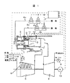
以下、本発明の実施例について図面を用いて説明する。図1は本発明の一実施例であるガスタービンの系統構成を示す。
【0012】
本図に示すように、2段式燃焼器1においては、拡散燃焼が行われる第1段燃焼部2と予混合燃焼が行われる第2段燃焼部3を有している。本実施例の様な2段式燃焼器を有するガスタービンでは、起動から定格負荷に至るまでの間の燃空比、則ち、燃料量と空気量の比率の変化が非常に広い範囲においても、低NOx化の達成が可能な方式としている。すなわち、本実施例では低NOx化を達成するため、起動から定格負荷まで使用される第1段燃焼部2には、作動域が広い拡散燃焼方式が採用され、起動から低負荷域においては、第1段燃焼部2による単独燃焼とし、その後高負荷域でも低NOx化を図る為、予混合燃焼方式を採用した第2段燃焼部3と第1段燃焼部2の同時燃焼へと燃焼状態が移行するように形成されている。
【0013】
また、上記燃空比の制御に際し、燃料側は、2段式燃焼器1に燃料を投入する燃料系統に設置された第1段燃焼用燃料弁4a及び第2段燃焼用燃料弁4bによって調整される。なお、第1段燃焼用燃料弁4aは、2段式燃焼器1の第1段燃焼部2に燃料を供給する第1段燃焼部燃料供給系統4xに設置され、第2段燃焼用燃料弁4bは、同じく第2段燃焼部3に燃料を供給する第2段燃焼部燃料供給系統4yに設置される。
【0014】
一方、空気側は、空気圧縮機5の入口側に設けられた入口案内翼6と称される可変翼によって実施される。通常、ガスタービン負荷運転中は、必要とする負荷の要求量に応じて、制御装置7からの信号によって、上記燃料弁4a,4bと入口案内翼6を調整し、安定した燃焼状態を維持出来る燃空比に調整している。しかし、上記の如く、広範囲に渡って、燃空比を適切に調整する必要がある一方で、燃焼は燃焼器の固体差,燃焼用空気の温度や湿度の変化、または燃料の発熱量や成分の変化により微妙に変化するものである。特に燃焼器に供給される燃料や空気の中に一過性の異物混入等の外乱が発生した場合、過渡的に燃焼器の燃焼状態が大きく変化し、第2段燃焼部の火炎逆流や火炎喪失等の異常燃焼状態となることがある。
【0015】
これら異常燃焼状態は、図1に示すタービン部8の排気側の周方向に設置している複数の排気ガス温度測定用熱電対9による測定結果、あるいは、燃焼器1の第2段燃焼部3に位置する予混合器10内に設置される燃焼器メタル温度測定用熱電対11、あるいは燃焼器内圧センサ12、あるいは発電機13の出力による測定結果からとらえることが可能である。また、上記の他にも、異常燃焼状態を確認する手段として、上記測定部位と同様の傾向を示す、燃焼器内ガス温度,燃焼器廻り配管内ガス温度,燃焼器廻り配管メタル温度等が挙げられる。
【0016】
上記検知器の信号は、制御装置7に送られることで異常燃焼状態の判定に用いられる。そして、検知器の信号が許容値を超えたことによって、第2段燃焼部3に火炎逆流が発生したと判断された場合、第1段燃焼用燃料弁4a,第2段燃焼用燃料弁4bの弁開度を調整して、燃焼器に供給する全燃料流量に対する第2段燃焼部3に供給する燃料流量の比率を下げ、同一負荷設定のまま運転を継続させる。逆に、第2段燃焼部3に火炎喪失が発生したと判断された場合、第1段燃焼用燃料弁4a,第2段燃焼用燃料弁4bの弁開度を調整し、燃焼器に供給する全燃料流量に対する第2段燃焼部3に供給する燃料流量の比率を上げ、同一負荷設定のまま運転を継続させる。その後、前記状態量が許容値以内に戻り、または更に所定時間を経過した場合は、異常状態から回避したものとして制御量を異常前設定値まで自動復帰させる。
【0017】
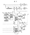
図2は、図1に示す制御装置7内で、本実施例の燃料比率を制御する為のブロック図を示したものである。
【0018】
燃焼器の燃料比率制御は、予混合(第2段)燃料比率設定18aが燃料制御信号14に対する関数として与えられており、それに予混合燃料流量比率低減バイアス信号42および予混合燃料流量比率増大バイアス信号43を減算器15および加算器16により補正し、さらに燃料制御信号14を乗算器17により乗算して第2段燃料制御信号20を作成する。また、第1段燃料制御信号21は、燃料制御信号14から減算器15により第2段燃料制御信号20を差し引いて作成する。従って第2段燃料制御信号20と第1段燃料制御信号21の合計は常に燃料制御信号14と一致することになる。さらに、第1段燃焼用燃料弁開度信号22は、第1段燃料制御信号21に対する関数として関数発生器18bにより与えられ、第2段燃焼用燃料弁開度信号23は第2段燃料制御信号20に対する関数として関数発生器18cにより与えられる。
【0019】
本図において、異常燃焼時の予混合燃料比率の補正方法を以下説明する。まず、火炎逆流に関しては、各燃焼器の第2段燃焼部に取り付けられた熱電対11により検出された燃焼器メタル温度24を取り込み、それらの燃焼器メタル温度実測値に対し、個々の許容温度,変動幅,変化率のうちのいずれかが、演算装置
25a〜25cにより、予め設定していた許容値を越えたと判断された場合は燃焼異常と見なし、異常燃焼を検知した信号26,27,28を発する。さらに演算装置29において、異常燃焼を検知した信号26,27,28の内いずれかからの送信、あるいはそれらの組み合わせにより設けられた制限条件が成立した場合には燃焼器メタル温度高信号30を発する。
【0020】
同様に、各燃焼器に取り付けられた熱電対により検出された燃焼器ガス温度を取り込み、本図では省略しているが前記燃焼器メタル温度と同様に、その絶対値,変動幅,変化率のうちのいずれかが、許容値を越えたと判断された場合は燃焼異常と見なし、異常信号の送信あるいはそれらの組み合わせにより設けられた制限条件が成立した場合には燃焼器ガス温度高信号31を発する。
【0021】
同様に、各燃焼器に取り付けられた燃焼器内圧センサ12により検出された燃焼振動信号を取り込み、その絶対値,変動幅,変化率のうちのいずれかが、許容値を越えたと判断された場合は燃焼異常と見なし、異常信号の送信あるいはそれらの組み合わせにより設けられた制限条件が成立した場合には燃焼器内圧変動高信号32を発する。
【0022】
さらに、演算装置29において上記燃焼器メタル温度高信号30,燃焼器ガス温度高信号31,燃焼器内圧変動高信号32の内いずれかからの送信、あるいはそれらの組み合わせにより設けられた制限条件が成立した場合には火炎逆流判定信号37を発する。火炎逆流判定信号37が発信されると、予混合燃料流量比率低減バイアス信号42は、スイッチ40により信号発生器41からの信号0%から関数発生器18dによる燃料制御信号14の関数に切り替わり、予混合燃料比率が予混合燃料流量比率低減バイアス信号42の量だけ下げられることになる。
【0023】
次に、火炎喪失に関しては、各燃焼器の第2段燃焼部に取り付けられた熱電対11により検出された燃焼器メタル温度,ガス温度,ガスタービン排気側の周方向に設置した複数の排気ガス温度測定用熱電対9により検出された排ガス温度、および発電機出力信号を取り込み、本図では省略しているが前記燃焼器メタル温度と同様に、その絶対値,変動幅,変化率のうちのいずれかが、許容値を越えたと判断された場合は燃焼異常と見なし、異常信号の送信あるいはそれらの組み合わせにより設けられた制限条件が成立した場合に、燃焼器メタル温度低信号33,燃焼器ガス温度低信号34,ガスタービン排ガス温度偏差大信号35および発電機出力低信号36を発する。
【0024】
さらに、演算装置29において上記燃焼器メタル温度低信号33,燃焼器ガス温度低信号34,ガスタービン排ガス温度偏差大信号35および発電機出力低信号36の内いずれかからの送信、あるいはそれらの組み合わせにより設けられた制限条件が成立した場合には火炎喪失判定信号38を発する。火炎喪失判定信号38が発信されると予混合燃料流量比率増大バイアス信号43は、スイッチ40により信号発生器41からの信号0%から関数発生器18eによる燃料制御信号14の関数に切り替わり、予混合燃料比率が予混合燃料流量比率増大バイアス信号43の量だけ上げられることになる。
【0025】
ここで、予混合燃料比率が前記バイアスにより調整されれば異常燃焼が回避され、火炎逆流判定信号37もしくは火炎喪失判定信号38がリセットされるが、異常燃焼を発生させた外乱の静定を考慮して、タイムディレイ・オフタイマ39により所定時間αの間保持後にリセットされる。信号がリセットされるとスイッチ40により、関数発生器18d,18eによる燃料制御信号14の関数から、信号発生器41からの信号0%に切り替わり、予混合燃料流量比率低減バイアス信号42もしくは予混合燃料比率増大バイアス信号43は0となり、予混合燃料比率は異常前設定値まで自動復帰する。
【0026】
さらに、何らかの理由で予混合燃料比率が前記バイアスにより調整さても異常燃焼が回避されなかった場合の後備保護として、タイムディレイ・オンタイマ
44により所定時間βの間、火炎逆流判定信号37もしくは火炎喪失判定信号
38がリセットされない場合には、第1段単独燃焼負荷へのランバック信号45を発し、負荷を降下させると共に、第2段燃焼用燃料を完全に遮断するようにしている。
【0027】
以上説明してきたように、本実施例によれば、2段式燃焼器を有するガスタービンにおいて、火炎逆流および火炎喪失の燃焼異常が発生した場合に、第2段燃焼部に供給する燃料の比率を変化させることにより、燃料系統構成等を複雑化すること無く、ガスタービンの負荷変動を最小限に抑えながら異常燃焼を回避することができる。
【0028】
また、逆火等の異常燃焼は異物混入等の一時的な外乱で発生することが多いため、従来技術では、逆火した燃料流量条件を回避するよう設定値を変更して運転した場合、外乱が無くなった通常運転時には、逆に火炎喪失に対する裕度が少なくなる可能性があった。これに対して、本実施例では上記運転状態で、燃焼器またはガスタービンの燃焼状態を示す状態量を監視し、機器に問題がないことが確認できれば、当初運転状態の設定値に戻すことにより、速やかに通常運転状態に復帰することが可能となる。
【0029】
以上のことから、2段式低NOx燃焼器の信頼性および運用性が向上する効果がある。
【0030】
予混合燃焼における火炎の逆流および火炎喪失(吹き消え)は、予混合気の流速と、燃焼速度のアンバランスで発生する。つまり予混合気流速に対し燃焼速度が速い場合には火炎が予混合気の流れに逆行して逆流し、逆に予混合気流速に対し燃焼速度が遅い場合には火炎が予混合気の流れに流され吹き消えてしまう。従って、火炎逆流時には予混合気の燃空比を小さくして燃焼速度を下げれば回復可能であり、逆に吹き消えは、燃空比を高くして燃焼速度を上げることにより再び安定燃焼可能になる。
【0031】
第2段燃焼部の逆火を解消するため、第2段燃料をほぼ遮断し、第2段燃料の大部分を第1段燃焼部へ切り替える必要がある場合には、第1段燃焼ノズルの容量制限等から、従来技術のように新たな燃料分岐配管や、第1段燃料ノズルに予備燃料孔を設ける必要がある。しかし、第2段燃料のほとんどを第1段燃焼部へ切り替えた場合には、ガスタービンから排出されるNOx量が非常に大きくなり、NOx低減のため負荷を下げる必要が生じ、同一負荷での継続運転は困難である。
【0032】
そこで、異常燃焼を解消するために必要な燃空比変化量を検討した結果、10%程度の変化でも効果があることが判り、新たな分岐燃料系統を追加する必要がなく、燃料比率の変更で対応できることが判明した。尚、この程度の変化では
NOxの変化も大きくなく、継続運転も可能となる。
【0033】
以上の理由から、本実施例では2段式燃焼器を有するガスタービンにおいて、特に燃焼が不安定となりやすい第2段燃焼部の燃焼異常発生時の制御方法として、第1段燃焼部と第2段燃焼部に供給する燃料の流量比率を変化させて継続運転するため、トータルの燃料流量は変化せず、さらに新規の分岐燃料系統を追加しないため、分岐燃料が燃焼開始するまでの時間の遅れも無く、その結果負荷変動はほとんど発生しなくなる。
【0034】
また、火炎逆流発生時は、第2段燃焼部の燃料流量比率を下げることにより、第2段燃焼部の燃空比が小さくなり、燃焼速度が遅くなるため、火炎の逆流を解消可能となる。逆に火炎喪失時は、第2段燃焼部の燃料流量比率を上げることにより、第2段燃焼部の燃空比が大きくなり、燃焼速度が速くなるため、再び安定燃焼可能となる。ここで、第1段燃焼部も燃料流量比率の変化により燃空比が変化するが、拡散燃焼のため安定燃焼裕度が広く、安定燃焼状態の維持は可能である。
【0035】
異常燃焼の検出は、第2段燃焼部の火炎逆流に関しては、燃焼器廻り(特に予混合器内)のメタル温度およびガス温度の急激な上昇および燃焼器内圧変動(燃焼振動)の増加等により、燃焼器の燃焼状態の変化を検知することができる。
【0036】
逆に第2段燃焼部の火炎喪失については、燃焼器廻り(特に予混合器内)のメタル温度およびガス温度の急激な低下により燃焼器の燃焼状態の変化を検知することができると共に、ガスタービンに設けられた複数の燃焼器のうち一部の燃焼器に火炎喪失が生じるケースでは、各燃焼器の燃焼ガス温度に偏差を生じることから、タービン排気側の周方向に設置されている複数個の排気ガス温度測定用熱電対の測定値の偏差(最高温度を示す熱電対と最低温度を示す熱電対の温度差)により検出可能である。さらに全数の燃焼器の第2段燃焼部に同時に火炎喪失が生じるケースでは、排気ガス温度測定用熱電対の測定値の偏差はほとんど上昇しないが、燃焼効率が低下するため、ガスタービン出力の急激な低下により検知可能となる。
【0037】
異常状態の判定条件としては、前記状態量の絶対値,変動幅または変化率の内の少なくとも1つ、あるいはそのいずれかの組み合わせとすることで判定可能となる。さらに、異常燃焼は主に一時的な外乱によって生じるため、上記燃料流量比率変更後の継続運転により、異常燃焼からの回避が確認された場合、またはさらに所定時間を経過した場合は、制御量を異常発生前の設定値まで自動復帰させることで、すみやかに通常運転に復帰可能となる。
【0038】
【発明の効果】
以上のように、本発明によれば、異常燃焼が発生した場合でもガスタービンの負荷変動を抑制することができるガスタービンの制御方法を提供できるという効果を奏する。
【図面の簡単な説明】
【図1】本発明の一実施例であるガスタービンの系統構成図。
【図2】本発明の一実施例である制御ブロック図。
【符号の説明】
1…2段式燃焼器、2…第1段燃焼部、3…第2段燃焼部、4a…第1段燃焼用燃料弁、4b…第2段燃焼用燃料弁、5…空気圧縮機、6…入口案内翼、7…制御装置、8…ガスタービン、9…排気ガス温度測定熱電対、10…予混合器、11…燃焼器メタル温度測定用熱電対、12…燃焼器内圧センサ、13…発電機、14…燃料制御信号、15…減算器、16…加算器、17…乗算器、18…関数発生器、19…第2段燃料流量比率、20…第2段燃料制御信号、21…第1段燃料制御信号、22…第1段燃焼用燃料弁開度信号、23…第2段燃焼用燃料弁開度信号、24…燃焼器メタル温度、25a〜25c…演算装置、26,27,28…信号、29…演算装置、30…燃焼器メタル温度高信号、31…燃焼器ガス温度高信号、32…燃焼器内圧変動高信号、33…燃焼器メタル温度低信号、34…燃焼器ガス温度低信号、35…ガスタービン排ガス温度偏差大信号、36…発電機出力低信号、37…火炎逆流判定信号、38…火炎喪失判定信号、39…タイムディレイ・オフタイマ、40…スイッチ、41…信号発生器、42…予混合燃料流量比率低減バイアス信号、43…予混合燃料流量比率増大バイアス信号、44…タイムディレイ・オンタイマ、45…第1段単独燃焼負荷へのランバック信号。[0001]
BACKGROUND OF THE INVENTION
The present invention relates to a method for controlling a gas turbine including a two-stage combustor having a first-stage combustion section that performs diffusion combustion and a second-stage combustion section that performs premix combustion.
[0002]
[Prior art]
A gas turbine having a plurality of two-stage combustors generally employed includes a first stage combustion section in which diffusion combustion is performed and a second stage combustion section in which premixed combustion is performed. One of the features of the combustor of this kind of gas turbine is that the change range of the fuel-air ratio from the start to the rated load, that is, the ratio of the fuel amount to the air amount is very wide.
[0003]
A gas turbine having a two-stage combustor is a system that can achieve low NOx even in this very wide change range of the fuel-air ratio, and the fuel of the first-stage combustion section and the second-stage combustion section. This is achieved through control. In other words, in the first stage combustion section that is used from start-up to the rated load, a diffusion combustion system with a wide operating range is adopted, and thereafter, the NOx reduction is also achieved in the high load range from the single combustion in the first stage combustion section. In order to achieve this, the combustion state shifts to the simultaneous combustion of the second stage combustion section and the first stage combustion section.
[0004]
Here, the second-stage combustion section with low NOx generation amount is sensitive to the fuel-air ratio and the stable combustion range is narrow, so the fuel amount and air amount are controlled finely within the stable combustion range. is doing.
[0005]
However, combustion changes slightly due to differences in combustors, changes in the temperature and humidity of combustion air, or changes in the amount of heat generated by fuel and components. In particular, when disturbances such as transient foreign matter are mixed in the fuel or air supplied to the combustor, the combustion state of the combustor may change greatly and the stable combustion state may not be maintained. .
[0006]
In such a case, even if the secondary fuel that is the fuel of the second stage combustion section is input to the second stage combustion section, the fire transfer from the first stage combustion section to the second stage combustion section can be performed. Therefore, the secondary fuel may not be ignited or the flame of the second stage combustion part may be lost. On the other hand, there was a risk that the flame of the second stage combustion part would flow backward and the part would burn out.
[0007]
Conventionally, as a method for avoiding such abnormal combustion, for example, Japanese Patent Laid-Open No. Hei 7-
As shown in Japanese Patent No. 54671, a back-flow flame detection sensor is installed in the premixing duct, and the downstream of the fuel distribution valve of the second stage (main) fuel system is branched, and the fuel is switched to the branched flow path. A valve is provided, and a spare fuel hole for injecting the switching fuel is provided in the first stage (pilot) fuel nozzle, and the fuel switching valve is controlled when detecting the reverse flow flame, so that at least a part of the second stage fuel is provided. Is injected from the preliminary fuel hole of the first stage fuel nozzle through the branch flow path, and when extinguishing of the backflow flame is detected, the set value is changed so as not to reproduce the equivalent ratio of the backfired, and the normal operation is restored. A control method is known.
[0008]
[Problems to be solved by the invention]
In the above-described prior art, not only the structure of the fuel system and the structure of the first stage fuel nozzle are complicated, but when a backfire is detected, a new fuel is added to the branch pipe and the fuel nozzle hole that have not been used so far. May cause load fluctuations due to time delay until the branch fuel starts to burn (the time when the branch pipe is filled with fuel and the ignition time of the branch fuel), the ignition failure of the branch fuel, etc. was there.
[0009]
The present invention has been made in view of the above-described points, and an object of the present invention is to provide a gas turbine control method capable of suppressing the load fluctuation of the gas turbine even when abnormal combustion occurs. It is in.
[0010]
[Means for Solving the Problems]
In order to achieve the above object, a gas turbine operating method of the present invention comprises a plurality of combustors, the first stage combustor in which the combustor performs diffusion combustion, and the second stage combustion section in which premixed combustion is performed. When the combustion state of the combustor or the gas turbine is monitored and abnormal combustion is detected, the total fuel flow rate supplied to the combustor is not changed and the total fuel flow rate is not changed. The operation is continued by changing the ratio of the fuel flow rate supplied to the second-stage combustion section.
[0011]
DETAILED DESCRIPTION OF THE INVENTION
Embodiments of the present invention will be described below with reference to the drawings. FIG. 1 shows a system configuration of a gas turbine according to an embodiment of the present invention.
[0012]
As shown in the figure, the two-
[0013]
Further, when controlling the fuel-air ratio, the fuel side is adjusted by the first-stage combustion fuel valve 4a and the second-stage
[0014]
On the other hand, the air side is implemented by variable vanes called inlet guide vanes 6 provided on the inlet side of the air compressor 5. Normally, during gas turbine load operation, the
[0015]
These abnormal combustion states are measured by a plurality of exhaust gas temperature measuring thermocouples 9 installed in the circumferential direction on the exhaust side of the
[0016]
The signal from the detector is sent to the control device 7 to be used for determining an abnormal combustion state. When it is determined that a flame backflow has occurred in the second stage combustion unit 3 because the detector signal exceeds the allowable value, the first stage combustion fuel valve 4a and the second stage
[0017]
FIG. 2 is a block diagram for controlling the fuel ratio of this embodiment in the control device 7 shown in FIG.
[0018]
Combustor fuel ratio control is provided with a premixed (second stage) fuel ratio setting 18a as a function of the
[0019]
In this figure, the correction method of the premixed fuel ratio at the time of abnormal combustion is demonstrated below. First, regarding the flame reverse flow, the combustor metal temperature 24 detected by the thermocouple 11 attached to the second stage combustion portion of each combustor is taken in, and the individual permissible temperature with respect to the measured combustor metal temperature. , The fluctuation range, and the rate of change are determined by the
[0020]
Similarly, the combustor gas temperature detected by the thermocouple attached to each combustor is taken in, and although not shown in this figure, the absolute value, fluctuation range, and rate of change are similar to the combustor metal temperature. When one of them is determined to exceed the allowable value, it is regarded as a combustion abnormality, and when the restriction condition provided by the transmission of the abnormality signal or a combination thereof is satisfied, the combustor gas temperature high signal 31 is generated. .
[0021]
Similarly, when a combustion vibration signal detected by a combustor internal pressure sensor 12 attached to each combustor is captured, and it is determined that any one of the absolute value, fluctuation range, and rate of change exceeds an allowable value. Is regarded as a combustion abnormality, and a combustor internal pressure fluctuation
[0022]
Further, in the
[0023]
Next, regarding flame loss, a plurality of exhaust gases installed in the circumferential direction on the combustor metal temperature, gas temperature, gas turbine exhaust side detected by the thermocouple 11 attached to the second stage combustion section of each combustor. The exhaust gas temperature detected by the temperature measuring thermocouple 9 and the generator output signal are taken in, and although not shown in the figure, the absolute value, fluctuation range, and rate of change are omitted as in the case of the combustor metal temperature. If it is determined that any of the values exceeds the allowable value, it is regarded as a combustion abnormality, and when the restriction condition provided by the transmission of the abnormality signal or a combination thereof is satisfied, the combustor metal temperature
[0024]
Further, in the
[0025]
Here, if the premixed fuel ratio is adjusted by the bias, abnormal combustion is avoided and the flame backflow determination signal 37 or the flame
[0026]
Further, as a pre-protection when abnormal combustion is not avoided even if the premixed fuel ratio is adjusted by the bias for some reason, the flame reverse flow determination signal 37 or the flame loss determination is performed for a predetermined time β by the time delay / on timer 44. If the
[0027]
As described above, according to the present embodiment, in the gas turbine having the two-stage combustor, the ratio of the fuel to be supplied to the second-stage combustion section when a combustion abnormality of flame backflow and flame loss occurs. Thus, abnormal combustion can be avoided while minimizing the load fluctuation of the gas turbine without complicating the fuel system configuration and the like.
[0028]
In addition, abnormal combustion such as flashback often occurs due to temporary disturbance such as contamination of foreign matter, so in the conventional technology, when operating with changing the set value so as to avoid backfired fuel flow conditions, On the other hand, during normal operation when there is no longer any possibility, the tolerance for loss of flame may be reduced. On the other hand, in this embodiment, in the above operation state, the state quantity indicating the combustion state of the combustor or the gas turbine is monitored, and if it can be confirmed that there is no problem with the equipment, it is returned to the set value of the initial operation state. It becomes possible to quickly return to the normal operation state.
[0029]
From the above, there is an effect of improving the reliability and operability of the two-stage low NOx combustor.
[0030]
In the premixed combustion, the backflow of the flame and the loss of the flame (blown out) occur due to an unbalance between the flow velocity of the premixed gas and the combustion speed. In other words, when the combustion speed is faster than the premixed gas flow rate, the flame flows backward to the premixed gas flow, and conversely, when the combustion speed is slower than the premixed gas flow rate, the flame flows through the premixed gas flow. It will be washed away and blown away. Therefore, during the reverse flow of the flame, it can be recovered by reducing the fuel / air ratio of the premixed gas and lowering the combustion speed. Conversely, blow-off can be stabilized again by increasing the fuel / air ratio and increasing the combustion speed. Become.
[0031]
In order to eliminate the flashback in the second stage combustion section, when the second stage fuel is almost cut off and most of the second stage fuel needs to be switched to the first stage combustion section, the first stage combustion nozzle Due to capacity restrictions and the like, it is necessary to provide a spare fuel hole in a new fuel branch pipe or the first stage fuel nozzle as in the prior art. However, when most of the second stage fuel is switched to the first stage combustion section, the amount of NOx discharged from the gas turbine becomes very large, and it is necessary to reduce the load to reduce NOx. Continuous operation is difficult.
[0032]
Therefore, as a result of examining the amount of change in fuel-air ratio necessary to eliminate abnormal combustion, it was found that even a change of about 10% was effective, and it was not necessary to add a new branch fuel system, and the fuel ratio was changed. It became clear that it can respond. It should be noted that with such a change, the change in NOx is not large and continuous operation is possible.
[0033]
For the reasons described above, in the present embodiment, in the gas turbine having the two-stage combustor, as a control method when a combustion abnormality occurs in the second-stage combustion section where combustion is likely to be unstable, the first-stage combustion section and the second-stage combustion section are used. Since the continuous operation is performed by changing the flow rate ratio of the fuel supplied to the stage combustion section, the total fuel flow rate does not change and no new branch fuel system is added, so the time delay until the branch fuel starts to burn is delayed. As a result, almost no load fluctuation occurs.
[0034]
Further, when the flame backflow occurs, the fuel flow ratio of the second stage combustion section is reduced by reducing the fuel flow rate ratio of the second stage combustion section, and the combustion speed becomes slow, so that the flame backflow can be eliminated. . On the other hand, when the flame is lost, increasing the fuel flow rate ratio of the second stage combustion section increases the fuel-air ratio of the second stage combustion section and increases the combustion speed, so that stable combustion is possible again. Here, although the fuel-air ratio also changes in the first stage combustion portion due to the change in the fuel flow rate ratio, the stable combustion margin is wide because of diffusion combustion, and the stable combustion state can be maintained.
[0035]
Abnormal combustion is detected due to a rapid rise in the metal temperature and gas temperature around the combustor (especially in the premixer) and an increase in combustor internal pressure fluctuation (combustion vibration), etc. The change in the combustion state of the combustor can be detected.
[0036]
Conversely, regarding the loss of flame in the second stage combustion section, it is possible to detect a change in the combustion state of the combustor by a rapid decrease in the metal temperature and gas temperature around the combustor (especially in the premixer), In a case where flame loss occurs in some of the plurality of combustors provided in the turbine, a deviation occurs in the combustion gas temperature of each combustor. It can be detected by the deviation of the measured values of the individual exhaust gas temperature thermocouples (temperature difference between the thermocouple showing the maximum temperature and the thermocouple showing the minimum temperature). Furthermore, in the case where flame loss occurs simultaneously in the second stage combustion parts of all the combustors, the deviation of the measured value of the exhaust gas temperature measurement thermocouple hardly increases, but the combustion efficiency decreases, so the gas turbine output suddenly decreases. It becomes possible to detect by a small drop.
[0037]
The determination condition for the abnormal state can be determined by using at least one of the absolute value, fluctuation range, or rate of change of the state quantity, or any combination thereof. Furthermore, abnormal combustion occurs mainly due to temporary disturbances. Therefore, if the avoidance from abnormal combustion is confirmed by continuous operation after changing the fuel flow rate ratio, or if a predetermined time has elapsed, the control amount is reduced. By automatically returning to the set value before the occurrence of an abnormality, it is possible to return to normal operation immediately.
[0038]
【The invention's effect】
As described above, according to the present invention, there is an effect that it is possible to provide a control method of a gas turbine that can suppress a load fluctuation of the gas turbine even when abnormal combustion occurs.
[Brief description of the drawings]
FIG. 1 is a system configuration diagram of a gas turbine according to an embodiment of the present invention.
FIG. 2 is a control block diagram according to an embodiment of the present invention.
[Explanation of symbols]
DESCRIPTION OF
Claims (9)
燃焼器またはガスタービンの燃焼状態を監視して、異常燃焼を検出した場合に、前記燃焼器に供給する全燃料流量は変えずに、該全燃料流量に対する前記第2段燃焼部に供給する燃料流量の比率を変化させて運転を継続することを特徴とするガスタービンの制御方法。In a method for controlling a gas turbine, comprising: a first stage combustor that includes a plurality of combustors, wherein the combustor performs diffusion combustion; and a second stage combustion unit that performs premix combustion.
When the combustion state of the combustor or gas turbine is monitored and abnormal combustion is detected, the total fuel flow rate supplied to the combustor is not changed, and the fuel supplied to the second stage combustion unit with respect to the total fuel flow rate A method for controlling a gas turbine, characterized in that the operation is continued by changing a flow rate ratio.
燃焼器またはガスタービンの燃焼状態を監視して、異常燃焼を検出した場合に、前記燃焼器に供給する全燃料流量は変えずに、該全燃料流量に対する前記第2段燃焼部に供給する燃料流量の比率を変化させて運転を継続すると共に、その状態で運転継続中に異常燃焼の検出が行われなくなった場合、または前記の状態で所定時間を経過した場合に、異常燃焼を検出する前の制御状態に戻すこと制御を行うことを特徴とするガスタービンの制御方法。In a method for controlling a gas turbine, comprising: a first stage combustor that includes a plurality of combustors, wherein the combustor performs diffusion combustion; and a second stage combustion unit that performs premix combustion.
When the combustion state of the combustor or gas turbine is monitored and abnormal combustion is detected, the total fuel flow rate supplied to the combustor is not changed, and the fuel supplied to the second stage combustion unit with respect to the total fuel flow rate Before the abnormal combustion is detected when the abnormal combustion is not detected while the operation is continued while changing the flow rate ratio, or when the predetermined time has passed in the above state. A control method for a gas turbine, characterized by performing control to return to the control state.
燃焼器またはガスタービンの燃焼状態の状態量を監視して、前記状態量が許容値を越えた場合に異常燃焼とみなし、前記燃焼器に供給する全燃料流量に対する前記第2段燃焼部に供給する燃料流量の比率を変化させて運転を継続すると共に、その状態で運転継続中に前記状態量が許容値内に戻った場合、または前記の状態で所定時間を経過した場合に、異常燃焼から回避したものとして、前記第1段燃焼器と第2段燃焼部に供給する燃料の制御量を、異常燃焼とみなした前の設定値まで復帰させる制御を行うことを特徴とするガスタービンの制御方法。In a method for controlling a gas turbine, comprising: a first stage combustor that includes a plurality of combustors, wherein the combustor performs diffusion combustion; and a second stage combustion unit that performs premix combustion.
The state quantity of the combustion state of the combustor or the gas turbine is monitored, and when the state quantity exceeds an allowable value, it is regarded as abnormal combustion, and is supplied to the second stage combustion unit with respect to the total fuel flow rate supplied to the combustor. The fuel flow rate ratio is changed and the operation is continued, and when the state quantity returns to the allowable value during the operation in that state, or when a predetermined time elapses in the state, the abnormal combustion starts. As a means of avoidance, control of the gas turbine is characterized in that the control amount of the fuel supplied to the first stage combustor and the second stage combustor is returned to the set value before being regarded as abnormal combustion. Method.
前記複数個の第2段燃焼器の燃焼状態の状態量を監視して、何れかの前記第2段燃焼器のうち少なくとも1個所の状態量が許容値を越えた場合に異常燃焼とみなし、前記燃焼器に供給する全燃料流量に対する前記第2段燃焼部に供給する燃料流量の比率を変化させて運転を継続すると共に、その状態で運転継続中に前記状態量が許容値内に戻った場合、または前記の状態で所定時間を経過した場合に、異常燃焼から回避したものとして、前記第1段燃焼器と第2段燃焼部に供給する燃料の制御量を、異常燃焼とみなした前の設定値まで復帰させる制御を行うことを特徴とするガスタービンの制御方法。In a control method of a gas turbine including a combustor having a first stage combustor that performs diffusion combustion and a second stage combustion unit that is installed and performs premix combustion,
The state quantity of the combustion state of the plurality of second stage combustors is monitored, and when the state quantity of at least one of the second stage combustors exceeds an allowable value, it is regarded as abnormal combustion. The operation was continued by changing the ratio of the fuel flow rate to be supplied to the second stage combustion section with respect to the total fuel flow rate to be supplied to the combustor, and the state quantity returned to the allowable value during the operation in that state. Or when the predetermined amount of time has passed in the above state, the amount of fuel supplied to the first-stage combustor and the second-stage combustion section is regarded as abnormal combustion before being regarded as abnormal combustion. A control method for a gas turbine, wherein control is performed to return to a set value of.
Priority Applications (1)
| Application Number | Priority Date | Filing Date | Title |
|---|---|---|---|
| JP2000081717A JP3772633B2 (en) | 2000-03-17 | 2000-03-17 | Control method of gas turbine |
Applications Claiming Priority (1)
| Application Number | Priority Date | Filing Date | Title |
|---|---|---|---|
| JP2000081717A JP3772633B2 (en) | 2000-03-17 | 2000-03-17 | Control method of gas turbine |
Publications (2)
| Publication Number | Publication Date |
|---|---|
| JP2001263095A JP2001263095A (en) | 2001-09-26 |
| JP3772633B2 true JP3772633B2 (en) | 2006-05-10 |
Family
ID=18598618
Family Applications (1)
| Application Number | Title | Priority Date | Filing Date |
|---|---|---|---|
| JP2000081717A Expired - Lifetime JP3772633B2 (en) | 2000-03-17 | 2000-03-17 | Control method of gas turbine |
Country Status (1)
| Country | Link |
|---|---|
| JP (1) | JP3772633B2 (en) |
Cited By (1)
| Publication number | Priority date | Publication date | Assignee | Title |
|---|---|---|---|---|
| JP2013002451A (en) * | 2011-06-20 | 2013-01-07 | Alstom Technology Ltd | Method for operating combustion device and combustion device for implementing the method |
Families Citing this family (6)
| Publication number | Priority date | Publication date | Assignee | Title |
|---|---|---|---|---|
| JP2003173206A (en) | 2001-12-05 | 2003-06-20 | Hitachi Ltd | Power generation equipment remote operation support method and power generation equipment remote operation support system |
| GB0601775D0 (en) * | 2006-01-28 | 2006-03-08 | Rolls Royce Plc | An Actuator Arrangement And A Method Of Operating An Actuator |
| JP4760823B2 (en) * | 2007-12-17 | 2011-08-31 | 株式会社日立製作所 | Gas turbine monitoring and diagnostic equipment |
| JP5635948B2 (en) | 2010-07-23 | 2014-12-03 | 三菱日立パワーシステムズ株式会社 | Combustor control method and control apparatus |
| JP5836069B2 (en) * | 2011-10-31 | 2015-12-24 | 三菱日立パワーシステムズ株式会社 | Gas turbine and combustion control method for gas turbine |
| EP3008391B1 (en) | 2013-06-11 | 2020-05-06 | United Technologies Corporation | Combustor with axial staging for a gas turbine engine |
Family Cites Families (11)
| Publication number | Priority date | Publication date | Assignee | Title |
|---|---|---|---|---|
| JPH05187270A (en) * | 1992-01-13 | 1993-07-27 | Hitachi Ltd | Operation method of gas turbine combustor |
| JPH05187265A (en) * | 1992-01-13 | 1993-07-27 | Hitachi Ltd | Gas turbine combustion diagnostic device |
| JP2891020B2 (en) * | 1993-03-05 | 1999-05-17 | 日産自動車株式会社 | Combustor control device |
| JP3425191B2 (en) * | 1993-08-10 | 2003-07-07 | 株式会社東芝 | Gas turbine combustor |
| JP3502171B2 (en) * | 1994-12-05 | 2004-03-02 | 株式会社日立製作所 | Gas turbine control method |
| JP3453973B2 (en) * | 1995-12-27 | 2003-10-06 | 株式会社豊田中央研究所 | Control method of premixed combustion device |
| JP3446074B2 (en) * | 1996-03-26 | 2003-09-16 | 株式会社日立製作所 | Gas turbine combustion monitoring device |
| JPH10231739A (en) * | 1997-02-18 | 1998-09-02 | Hitachi Ltd | Gas turbine combustion monitoring device |
| JPH10317991A (en) * | 1997-05-15 | 1998-12-02 | Hitachi Ltd | gas turbine |
| JP3785760B2 (en) * | 1997-09-30 | 2006-06-14 | 日産自動車株式会社 | Combustor control device |
| JPH11264327A (en) * | 1998-03-19 | 1999-09-28 | Mitsubishi Heavy Ind Ltd | Misfire detecting method for gas turbine combustor |
-
2000
- 2000-03-17 JP JP2000081717A patent/JP3772633B2/en not_active Expired - Lifetime
Cited By (2)
| Publication number | Priority date | Publication date | Assignee | Title |
|---|---|---|---|---|
| JP2013002451A (en) * | 2011-06-20 | 2013-01-07 | Alstom Technology Ltd | Method for operating combustion device and combustion device for implementing the method |
| US9249979B2 (en) | 2011-06-20 | 2016-02-02 | Alstom Technology Ltd. | Controlling a combustion device to lower combustion-induced pulsations by changing and resetting fuel stagings at different rates of change |
Also Published As
| Publication number | Publication date |
|---|---|
| JP2001263095A (en) | 2001-09-26 |
Similar Documents
| Publication | Publication Date | Title |
|---|---|---|
| JP3502171B2 (en) | Gas turbine control method | |
| JP3783442B2 (en) | Control method of gas turbine | |
| EP2261487B1 (en) | Gas turbine controller | |
| US6530207B2 (en) | Gas turbine system | |
| JP2004027848A (en) | Gas turbine controller | |
| JP2019138157A (en) | Gas turbine combustor, gas turbine and control method of gas turbine combustor | |
| US9810159B2 (en) | Method and apparatus for controlling gas turbine combustor | |
| JP3772633B2 (en) | Control method of gas turbine | |
| JP3499026B2 (en) | Gas turbine fuel supply device | |
| JP5836069B2 (en) | Gas turbine and combustion control method for gas turbine | |
| US6357216B1 (en) | Flashback control for a gas turbine engine combustor having an air bypass system | |
| JP3828738B2 (en) | Gas turbine fuel control system | |
| JPH10317991A (en) | gas turbine | |
| JP2001108237A (en) | Gas turbine combustion equipment | |
| JP3643499B2 (en) | Gas turbine combustion apparatus and flame reverse flow detection method thereof | |
| JP3192041B2 (en) | Gas turbine combustion apparatus and control method thereof | |
| JP3472424B2 (en) | Gas turbine and method of operating gas turbine | |
| JP3086695B2 (en) | Gas turbine control device | |
| JPH05149544A (en) | Controller for gas turbine | |
| JP2000027660A (en) | Fuel and steam supply system for gas turbine combustor | |
| JPH10299511A (en) | Gas turbine combustion monitoring device | |
| JP3131804B2 (en) | Fuel distribution control device for gas turbine combustor | |
| JP3926075B2 (en) | Gas turbine combustor | |
| JP2001012257A (en) | Fuel and steam supply system for gas turbine combustor | |
| JPH02130226A (en) | Gas turbine control device |
Legal Events
| Date | Code | Title | Description |
|---|---|---|---|
| A977 | Report on retrieval |
Free format text: JAPANESE INTERMEDIATE CODE: A971007 Effective date: 20050614 |
|
| A131 | Notification of reasons for refusal |
Free format text: JAPANESE INTERMEDIATE CODE: A131 Effective date: 20050621 |
|
| A521 | Written amendment |
Free format text: JAPANESE INTERMEDIATE CODE: A523 Effective date: 20050817 |
|
| TRDD | Decision of grant or rejection written | ||
| A01 | Written decision to grant a patent or to grant a registration (utility model) |
Free format text: JAPANESE INTERMEDIATE CODE: A01 Effective date: 20060124 |
|
| A61 | First payment of annual fees (during grant procedure) |
Free format text: JAPANESE INTERMEDIATE CODE: A61 Effective date: 20060206 |
|
| R151 | Written notification of patent or utility model registration |
Ref document number: 3772633 Country of ref document: JP Free format text: JAPANESE INTERMEDIATE CODE: R151 |
|
| FPAY | Renewal fee payment (event date is renewal date of database) |
Free format text: PAYMENT UNTIL: 20090224 Year of fee payment: 3 |
|
| FPAY | Renewal fee payment (event date is renewal date of database) |
Free format text: PAYMENT UNTIL: 20100224 Year of fee payment: 4 |
|
| FPAY | Renewal fee payment (event date is renewal date of database) |
Free format text: PAYMENT UNTIL: 20100224 Year of fee payment: 4 |
|
| FPAY | Renewal fee payment (event date is renewal date of database) |
Free format text: PAYMENT UNTIL: 20110224 Year of fee payment: 5 |
|
| FPAY | Renewal fee payment (event date is renewal date of database) |
Free format text: PAYMENT UNTIL: 20120224 Year of fee payment: 6 |
|
| FPAY | Renewal fee payment (event date is renewal date of database) |
Free format text: PAYMENT UNTIL: 20120224 Year of fee payment: 6 |
|
| FPAY | Renewal fee payment (event date is renewal date of database) |
Free format text: PAYMENT UNTIL: 20130224 Year of fee payment: 7 |
|
| FPAY | Renewal fee payment (event date is renewal date of database) |
Free format text: PAYMENT UNTIL: 20130224 Year of fee payment: 7 |
|
| S111 | Request for change of ownership or part of ownership |
Free format text: JAPANESE INTERMEDIATE CODE: R313111 |
|
| R350 | Written notification of registration of transfer |
Free format text: JAPANESE INTERMEDIATE CODE: R350 |
|
| R250 | Receipt of annual fees |
Free format text: JAPANESE INTERMEDIATE CODE: R250 |
|
| R250 | Receipt of annual fees |
Free format text: JAPANESE INTERMEDIATE CODE: R250 |
|
| R250 | Receipt of annual fees |
Free format text: JAPANESE INTERMEDIATE CODE: R250 |
|
| R250 | Receipt of annual fees |
Free format text: JAPANESE INTERMEDIATE CODE: R250 |
|
| R250 | Receipt of annual fees |
Free format text: JAPANESE INTERMEDIATE CODE: R250 |
|
| R250 | Receipt of annual fees |
Free format text: JAPANESE INTERMEDIATE CODE: R250 |
|
| EXPY | Cancellation because of completion of term |