JP3772614B2 - projector - Google Patents
projector Download PDFInfo
- Publication number
- JP3772614B2 JP3772614B2 JP33349799A JP33349799A JP3772614B2 JP 3772614 B2 JP3772614 B2 JP 3772614B2 JP 33349799 A JP33349799 A JP 33349799A JP 33349799 A JP33349799 A JP 33349799A JP 3772614 B2 JP3772614 B2 JP 3772614B2
- Authority
- JP
- Japan
- Prior art keywords
- projector
- light
- prism
- fixed
- fixing
- Prior art date
- Legal status (The legal status is an assumption and is not a legal conclusion. Google has not performed a legal analysis and makes no representation as to the accuracy of the status listed.)
- Expired - Fee Related
Links
- 230000003287 optical effect Effects 0.000 claims description 89
- 238000001816 cooling Methods 0.000 claims description 13
- 239000004973 liquid crystal related substance Substances 0.000 description 38
- 238000005286 illumination Methods 0.000 description 12
- 238000003780 insertion Methods 0.000 description 10
- 230000037431 insertion Effects 0.000 description 10
- 238000000926 separation method Methods 0.000 description 5
- 239000000853 adhesive Substances 0.000 description 4
- 230000001070 adhesive effect Effects 0.000 description 4
- 230000000694 effects Effects 0.000 description 4
- 239000003086 colorant Substances 0.000 description 3
- 238000004519 manufacturing process Methods 0.000 description 3
- 239000011347 resin Substances 0.000 description 3
- 229920005989 resin Polymers 0.000 description 3
- FYYHWMGAXLPEAU-UHFFFAOYSA-N Magnesium Chemical compound [Mg] FYYHWMGAXLPEAU-UHFFFAOYSA-N 0.000 description 2
- 238000003491 array Methods 0.000 description 2
- 239000011248 coating agent Substances 0.000 description 2
- 238000000576 coating method Methods 0.000 description 2
- 229910052749 magnesium Inorganic materials 0.000 description 2
- 239000011777 magnesium Substances 0.000 description 2
- 239000011159 matrix material Substances 0.000 description 2
- 238000000034 method Methods 0.000 description 2
- 230000005855 radiation Effects 0.000 description 2
- 230000000630 rising effect Effects 0.000 description 2
- 238000001514 detection method Methods 0.000 description 1
- 230000006866 deterioration Effects 0.000 description 1
- 238000010586 diagram Methods 0.000 description 1
- 238000009792 diffusion process Methods 0.000 description 1
- 238000007599 discharging Methods 0.000 description 1
- 238000009826 distribution Methods 0.000 description 1
- 230000004907 flux Effects 0.000 description 1
- 229910052736 halogen Inorganic materials 0.000 description 1
- 150000002367 halogens Chemical class 0.000 description 1
- 230000007246 mechanism Effects 0.000 description 1
- QSHDDOUJBYECFT-UHFFFAOYSA-N mercury Chemical compound [Hg] QSHDDOUJBYECFT-UHFFFAOYSA-N 0.000 description 1
- 229910052753 mercury Inorganic materials 0.000 description 1
- 229910001507 metal halide Inorganic materials 0.000 description 1
- 150000005309 metal halides Chemical class 0.000 description 1
- 229910021420 polycrystalline silicon Inorganic materials 0.000 description 1
- 229920005591 polysilicon Polymers 0.000 description 1
- 230000008569 process Effects 0.000 description 1
- 238000003860 storage Methods 0.000 description 1
- 230000009466 transformation Effects 0.000 description 1
Images

Classifications
-
- H—ELECTRICITY
- H04—ELECTRIC COMMUNICATION TECHNIQUE
- H04N—PICTORIAL COMMUNICATION, e.g. TELEVISION
- H04N9/00—Details of colour television systems
- H04N9/12—Picture reproducers
- H04N9/31—Projection devices for colour picture display, e.g. using electronic spatial light modulators [ESLM]
- H04N9/3102—Projection devices for colour picture display, e.g. using electronic spatial light modulators [ESLM] using two-dimensional electronic spatial light modulators
- H04N9/3105—Projection devices for colour picture display, e.g. using electronic spatial light modulators [ESLM] using two-dimensional electronic spatial light modulators for displaying all colours simultaneously, e.g. by using two or more electronic spatial light modulators
-
- G—PHYSICS
- G03—PHOTOGRAPHY; CINEMATOGRAPHY; ANALOGOUS TECHNIQUES USING WAVES OTHER THAN OPTICAL WAVES; ELECTROGRAPHY; HOLOGRAPHY
- G03B—APPARATUS OR ARRANGEMENTS FOR TAKING PHOTOGRAPHS OR FOR PROJECTING OR VIEWING THEM; APPARATUS OR ARRANGEMENTS EMPLOYING ANALOGOUS TECHNIQUES USING WAVES OTHER THAN OPTICAL WAVES; ACCESSORIES THEREFOR
- G03B21/00—Projectors or projection-type viewers; Accessories therefor
- G03B21/14—Details
- G03B21/28—Reflectors in projection beam
-
- H—ELECTRICITY
- H04—ELECTRIC COMMUNICATION TECHNIQUE
- H04N—PICTORIAL COMMUNICATION, e.g. TELEVISION
- H04N9/00—Details of colour television systems
- H04N9/12—Picture reproducers
- H04N9/31—Projection devices for colour picture display, e.g. using electronic spatial light modulators [ESLM]
- H04N9/3141—Constructional details thereof
- H04N9/3144—Cooling systems
Landscapes
- Engineering & Computer Science (AREA)
- Multimedia (AREA)
- Signal Processing (AREA)
- Physics & Mathematics (AREA)
- General Physics & Mathematics (AREA)
- Projection Apparatus (AREA)
- Transforming Electric Information Into Light Information (AREA)
- Optical Elements Other Than Lenses (AREA)
Description
【0001】
【発明の属する技術分野】
本発明は、複数の色光を画像情報に応じて変調する複数の光変調装置と、当該複数の光変調装置で変調された変調光束を合成するプリズムと、前記プリズムが固定される光学部品用筐体とを備えたプロジェクタに関するものである。
【0002】
【背景技術】
従来より、3色の光を画像情報に応じて変調する3つの光変調装置と、当該光変調装置で変調された変調光束を合成するクロスダイクロイックプリズム、レンズ、ミラー等の光学部品を収納する光学部品用筐体である上下のライトガイドと、プリズムで合成された投写光束を拡大投写する投写レンズとを備えたプロジェクタが知られている。
【0003】
このようなプロジェクタは、会議、学会、展示会等でのマルチメディアプレゼンテーションに広く利用され、必要に応じて持ち込まれたり、終了後に他の場所に移して保管する場合もあるので、薄型化・小型化が促進されている。
【0004】
ここで、上記のような、3つの光変調装置を用いたプロジェクタにおいて、クロスダイクロイックプリズムは、通常、ライトガイドに形成された凹部に収納配置され、投写レンズが取り付けられる構造体に取り付けられる。従来は、この構造体の下面にネジを挿通し、プリズム下面の支持部材に形成されたネジ孔に螺合することで取り付けられている。
【0005】
【発明が解決しようとする課題】
しかしながら、このような従来のプロジェクタでは、ネジが螺合されるネジ孔の深さを十分確保できるように支持部材の厚さ寸法を大きくしておく必要があるので、当該支持部材の肉厚を薄くし、全体的にプロジェクタの高さ寸法を小さくして、当該プロジェクタの薄型化・小型化を図ることができないという問題がある。
【0006】
本発明の目的は、薄型化・小型化を図ることができるプロジェクタを提供することにある。
【0007】
【課題を解決するための手段】
本発明は、複数の色光を画像情報に応じて変調する複数の光変調装置と、当該複数の光変調装置で変調された変調光束を合成するプリズムと、前記プリズムが固定される光学部品用筐体とを備えたプロジェクタであって、前記プリズムは、当該プリズムを支持する支持部材を介して前記光学部品用筐体に固定され、前記支持部材は、前記プリズムが載置固定される載置部と、この載置部を前記光学部品用筐体に固定するための固定部とを備え、前記固定部は、前記載置部の周縁で、かつ、前記プリズムの側面よりも外側に設けられ、前記光学部品用筐体には、平面視で凹状に形成され、前記複数の光変調装置およびプリズムを内部に配置する凹部が形成され、前記凹部の内側には、前記光学部品用筐体における前記固定部が固定される部位とは反対側に、平面視で前記固定部を隠蔽被覆する被覆部が形成されていることを特徴とする。
【0008】
ここで、固定部としては、ネジを挿通するための挿通孔や、光学部品用筐体に係合する係合部材が形成されているものが採用できる。
【0009】
このような本発明によれば、載置部を光学部品用筐体に固定するための固定部を、載置部の周縁で、かつ、プリズムの側面よりも外側に設けることで、載置部にネジ孔等の固定手段を形成する程度の肉厚が不要となる。従って、載置部の肉厚を薄くすることが可能となるので、全体的にプロジェクタの高さ寸法を小さくすることが可能となる。これにより、プロジェクタの薄型化・小型化を図ることが可能となる。
【0010】
また、載置部を光学部品用筐体に固定するための固定部を、載置部の周縁で、かつ、プリズムの側面よりも外側に設けているので、例えば、固定部にネジを挿通するための挿通孔を形成し、光学部品用筐体側に挿通孔に対応したネジ孔を形成しておけば、プリズム載置面側からネジを挿通し、光学部品用筐体のネジ孔に螺合することが可能となる。これにより、プリズム載置面とは反対側からネジを挿通しなければならなかった従来の構造に比べて、プロジェクタの製造作業が容易となる。
プリズムおよび複数の光変調装置は、複数の画像が投写画面上の同じ位置に、フォーカスが合った状態で投写されるように調整した状態で、固定される。しかし、例えば、このような調整を行なった後、使用者がプリズムを移動させてしまった場合、プリズムおよび複数の光変調装置の位置がずれてしまい、スクリーン等に投写される画像が乱れてしまうおそれがある。
そこで、固定部を平面視で隠蔽被覆する被覆部を光学部品用筐体に形成し、固定部を被覆部で隠せば、固定部に外部から触れることが不可能となる。これにより、調整後のプロジェクタの画質劣化を未然に防止することが可能となる。
【0011】
以上において、前述の載置部は、4つの角部を有する平面略四角形状に形成され、固定部は、載置部の4つの角部のうち、対角線上の一対の角部に設けられていることが好ましい。
【0012】
このようにすれば、載置部をバランスよく光学部品用筐体に固定することが可能となるとともに、外力が加わってもずれることがない。
【0013】
また、前述の光学部品用筐体には、固定部が設けられていない対角線上で載置部の下面を支持する受部が形成されていることが望ましい。
【0014】
このようにすれば、直交する対角線上の4カ所で載置部が光学部品用筐体に支持および固定されるので、支持部材の固定がより一層強固となる。
【0018】
また、前述の光学部品用筐体は、複数の光変調装置を冷却するための冷却ファンが固定されるファン取付部を有し、このファン取付部は、被覆部を兼用していることが望ましい。
【0019】
このようにすれば、別途被覆部を装置内部に設ける必要がないので、構造の簡素化を図ることが可能となる。これにより、プロジェクタの組立作業が容易となる。
【0020】
【発明の実施の形態】
以下に本発明の実施の形態を図面に基づいて説明する。
【0021】
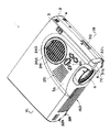
(1)装置の全体構成
図1、図2には、本実施形態に係るプロジェクタ1の概略斜視図が示され、図1は上面側から見た斜視図、図2は下面側から見た斜視図である。
【0022】
プロジェクタ1は、光源としての光源装置から出射された光束を赤(R)、緑(G)、青(B)の三原色に分離し、これらの各色光束を、光変調装置である液晶パネルを通して画像情報に対応させて変調し、変調した後の各色の変調光束をクロスダイクロイックプリズムにより合成して、投写レンズ6を介して投写面上に拡大表示する形式のものである。各構成部品は外装ケース2の内部に収納されているが、投写レンズ6はそのズーム機構により、必要に応じて外装ケース2から突出可能に設けられている。
【0023】
(2)外装ケースの構造
外装ケース2は、基本的には、装置上面を覆うアッパーケース3と、装置底面を構成するロアーケース4と、正面部分を覆うフロントケース5とから構成され、アッパーケース3およびロアーケース4がマグネシウムダイキャスト製で、フロントケース5が樹脂製である。
【0024】
アッパーケース3の上面右側(正面から見て右側)には、樹脂製のフィルタ交換蓋241で覆われた空気取入口240が設けられている。このフィルタ交換蓋241には、外部から取り入れた空気を装置内部へ冷却空気として導入するためのスリット状の開口241Aが形成され、当該フィルタ交換蓋241の内側には、エアフィルタ242(図8)が設けられている。このフィルタ交換蓋241をアッパーケース3の上面側から着脱することで、内部のエアフィルタ242を交換することが可能である。
【0025】
また、アッパーケース3の上面において、フィルタ交換蓋241の前方には、スピーカ250(図7)用の多数の連通孔251が穿設されている。連通孔251の側方には、プロジェクタ1の画質等を調整するための操作パネル60が設けられている。これらのフィルタ交換蓋241、連通孔251、および操作パネル60が設けられている部分は、図7、図8に示されるように、アッパーケース3の一部が上方に膨出した膨出部3Aになっており、この膨出部3Aによって形成される内部空間に前述のエアフィルタ242や、スピーカ250、操作パネル60用の回路基板61等が収容されている。
【0026】
図2において、ロアーケース4の底面には、内部に収納される光源ランプユニット8(図3、図4)を交換するためのランプ交換蓋27が設けられている。ロアーケース4の底面前方側の角部にはフット31R、31Lが設けられ、後方側の中央にはフット31Cが設けられている。なお、フット31R、31Lは、ダイヤル部分を回転させたり、レバー32R、32Lを操作することで突出方向に進退する構成であり、その進退量を調整することによって表示画面の高さや傾きを変更することが可能である。
【0027】
フロントケース5前面の向かって右側部分には、図示略のリモートコントローラからの光信号を受信するための受光部70が設けられている。フロントケース5の略中央には、装置内部の空気を排出する排気口160が設けられている。
【0028】
このような外装ケース2の空気取入口240寄りの側面および背面には、外部電源との接続用のACインレット50や各種の入出力端子群51が配置されている。
【0029】
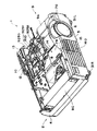
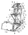
(3)装置の内部構造
図3〜図8には、プロジェクタ1の内部構造が示されている。図3は装置内部の概略斜視図、図4は光学系を示す斜視図、図5、図6は光学系の内部を示す斜視図、図7、図8はプロジェクタ1の垂直断面図である。
【0030】
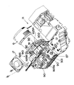
これらの図において、外装ケース2の内部には、光源ランプユニット8、電源としての電源ユニット9、光学ユニット10、ドライバーボード11(図8)、メインボード12、AVボード13などが配置されている。そして、本実施形態では、光源ランプユニット8、光学ユニット10、および前述した投写レンズ6により、図9にも示されるように、本発明に係る平面U字形状の光学系が構成され、各ボード11、12、13で本発明に係る制御系が構成されている。
【0031】
電源ユニット9は、光学系の投写レンズ6側の側部に配置された第1電源ブロック9A、平面U字型の光学系における中央の開口部14内、すなわち投写レンズ6と光源ランプユニット8との間に配置された第2電源ブロック9B、光学系の光源ランプユニット8側の側部に配置された第3電源ブロック9Cで構成されている。
【0032】
第1電源ブロック9Aは、前記ACインレット50を備えており、このACインレット50を通して得られる外部電源からの電力を第2電源ブロック9Bおよび第3電源ブロック9Cに分配供給している。
【0033】
第2電源ブロック9Bは、第1電源ブロック9Aから得られる電力を変圧して主に前記制御系を構成するメインボード12に供給している。この第2電源ブロック9Bの排気口160側には、当該第2電源ブロック9Bからの電力で駆動される補助排気ファン15が取り付けられている。
【0034】
第3電源ブロック9Cは、第1電源ブロック9Bから得られる電力を変圧して光源ランプユニット8内の光源としての光源装置183(図9)に供給している。すなわち、第3電源ブロック9Cは、最も消費電力の大きい光源装置183に電力を供給する必要から、第1、第2電源ブロック9A、9Bよりも大きく、装置1の前後にわたる大きさに設けられている。
【0035】
このような第1〜第3電源ブロック9A〜9Cは、投写レンズ6や光学ユニット10に先がけてロアーケース4にネジ等によって固定される。なお、第1電源ブロック9Aは、第2電源ブロック9Bにのみ電力を供給し、第3電源ブロック9Cはその第2電源ブロック9Bから電力が分配されるようにしてもよい。
【0036】
光源ランプユニット8は、プロジェクタ1の光源部分を構成するものであり、図9に示されるように、光源ランプ181および凹面鏡182からなる光源装置183と、この光源装置183を収納するランプハウジング184とを有している。
【0037】
なお、ランプハウジング184には、光源ランプ181の使用の有無を判別する使用有無判別部260が設けられている。
【0038】
そして、ランプハウジング184において、光源装置である光源ランプユニット8は、後述の光学部品用筐体であるライトガイド900を構成する上ライトガイド901と一体の収容部9021で覆われており、上述したランプ交換蓋27を開けて取り外せるように構成されている。収容部9021の前方には、排気口160に対応した位置に補助排気ファン15よりも大きい主排気ファン16が配置されている。そして、この主排気ファン16も第2電源ブロック9Bからの電力で駆動される。
【0039】
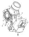
光学ユニット10は、光源ランプユニット8から出射された光束を、光学的に処理して画像情報に対応した光学像を形成するユニットであり、ライトガイド900を備えている。このライトガイド900は、樹脂製で箱状とされた上ライトガイド901と、マグネシウム製で蓋状とされた下ライトガイド902とで構成され、その内部には照明光学系923、色光分離光学系924、変調系925、およびクロスダイクロイックプリズム910が収容されている。また、下ライトガイド902には投写レンズ6が固定される鉛直なヘッド板903が設けられている。変調系925およびクロスダイクロイックプリズム910以外の光学ユニット10の光学素子は、上下のライトガイド901、902の間に挟まれて保持された構成となっている。これらの上ライトガイド901、下ライトガイド902は一体とされて、ロアーケース4の側に固定されている。
【0040】
クロスダイクロイックプリズム910は、ヘッド板903の裏面側であって、下ライトガイド902上に固定されている。変調系925を構成する各液晶パネル925R、925G、925Bは、クロスダイクロイックプリズム910の3側面と対向配置され、クロスダイクロイックプリズム910の対向する面に固定部材を介して接着固定されている。なお、各液晶パネル925R、925G、925Bの互いの位置関係は、液晶パネル925Bと液晶パネル925Rとがクロスダイクロイックプリズム910を挟んで対向した位置に設けられ、液晶パネル925Gがクロスダイクロイックプリズム910を挟んで投写レンズ6と対向した位置に設けられている。そして、これらの液晶パネル925R、925G、925Bは、クロスダイクロイックプリズム910の上方に位置しかつ前述の空気取入口240に対応して設けられた冷却ファンである吸気ファン17からの冷却用空気によって冷却される。この際、吸気ファン17駆動用の電力は、メインボード12からドライバーボード11を介して供給される。
【0041】
ドライバーボード11は、上述した変調系925の各液晶パネル925R、925G、925Bを制御するためのものであり、光学ユニット10の上方に配置されている。
【0042】
メインボード12は、プロジェクタ1全体を制御する制御回路が形成されたものであり、光学ユニット10の後方に立設されている。従って、メインボード12とドライバーボード11とは互いに直角に配置されてコネクタを介して電気的に接続されている。なお、このメインボード12には、使用有無判別部260からの情報を検出するランプ情報検出回路基板230が、ケーブルを介して接続されている。
【0043】
AVボード13は、前述の入出力端子群51を備えた回路基板であって、光学ユニット10とメインボード12との間に立設され、メインボード12に電気的に接続されている。
【0044】
以上の内部構造においては、吸気ファン17で吸引された冷却空気は、変調系925を冷却した後、各排気ファン15、16の回転によって各ボード11、12、13を冷却しながら光源ランプユニット8側に導かれる。そして、冷却空気は、ロアーケース4の底面に設けられた吸入口4A(図2)からの新たな冷却空気と共に、主に光源ランプユニット8に流れ込んで内部の光源装置183を冷却する。また、冷却空気の一部は第2電源ブロック9B側を流れ、他の一部は第3電源ブロック9C側を流れ、それぞれを冷却する。この後、冷却空気は各排気ファン15、16によって排気口160から装置1の前全面側に排気される。
【0045】
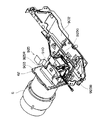
(4)光学系の構造
次に、図5、図9を参照して光学系の光学ユニット10について詳細に説明する。
【0046】
光学ユニット10は、それぞれ上ライトガイド901内に収容された照明光学系923と、色光分離光学系924と、リレー光学系927と、変調系925と、下ライトガイド902に固定されたクロスダイクロイックプリズム910と、下ライトガイド902のヘッド板903に固定された投写レンズ6とで構成されている。
【0047】
照明光学系923は、変調系925の3枚の液晶パネル925R、925G、925Bの画像形成領域をほぼ均一に照明するためのインテグレータ照明光学系であり、光源装置183と、第1のレンズアレイ921と、第2のレンズアレイ922と、反射ミラー931と、重畳レンズ932とを備えている。これらのレンズアレイ921、922、重畳レンズ932、および反射ミラー931は、上ライトガイド901の立上部分に支持された状態で配置されているとともに、脱落防止部材としてのクリップ7によって固定され、上ライトガイド901を図3に示す状態から反転させても脱落しないようになっている。
【0048】
照明光学系923を構成する光源装置183は、放射状の光線を出射する放射光源としての光源ランプ181と、光源ランプ181から出射された放射光をほぼ平行な光線束として出射する凹面鏡182とを有する。光源ランプ181としては、ハロゲンランプやメタルハライドランプ、または高圧水銀ランプが用いられることが多い。凹面鏡182としては、放物面鏡や楕円面鏡を用いることが好ましい。
【0049】
第1のレンズアレイ921は、略矩形状の輪郭を有する小レンズ9211がM行N列のマトリクス状に配列された構成を有している。各小レンズ9211は、光源から入射された平行な光束を複数の(すなわちM×N個の)部分光束に分割し、各部分光束を第2のレンズアレイ922の近傍で結像させる。各小レンズ9211の輪郭の形状は、液晶パネル925R、925G、925Bの画像形成領域の形状とほぼ相似形をなすように設定されている。例えば、液晶パネルの画像形成領域のアスペクト比(横と縦の寸法の比率)が4:3であるならば、各小レンズのアスペクト比も4:3に設定する。
【0050】
第2のレンズアレイ922も、第1のレンズアレイ921の小レンズ9211に対応するように、小レンズ9221がM行N列のマトリクス状に配列された構成を有している。第2のレンズアレイ922は、第1のレンズアレイ921から出射された各部分光束の中心軸(主光線)が重畳レンズ932の入射面に垂直に入射するように揃える機能を有している。ここで、重畳レンズ932は、複数の部分光束を3枚の液晶パネル925R、925G、925B上で重畳させる機能を有している。また、第2のレンズアレイ922は、図5に示されるように、反射ミラー931を挟んで第1のレンズアレイ921に対して90度傾いて配置されている。
【0051】
反射ミラー931は、第1のレンズアレイ921から出射された光束を第2のレンズアレイ922に導くためのミラーであり、照明光学系の構成によっては、必ずしも必要としない。例えば、第1のレンズアレイ921および光源が第2のレンズアレイ922に平行に設けられていれば不要である。
【0052】
色光分離光学系924は、本発明に係る光学部品としての2枚のダイクロイックミラー941、942と、反射ミラー943とを備え、照明光学系923の重畳レンズ932から出射される光を、赤、緑、青の3色の色光に分離する機能を有している。各ミラー941、942、943は、前述と同様に上ライトガイド901の立上部分に支持され、クリップ7によって上ライトガイド901に固定されている。
【0053】
リレー光学系927は、入射側レンズ954、リレーレンズ973、および反射ミラー971、972を備えており、これらの反射ミラー971、972もクリップ7によって上ライトガイド901に固定されている。
【0054】
変調系925の液晶パネル925R、925G、925Bは、例えば、ポリシリコンTFTをスイッチング素子として用いたものである。各液晶パネル925R、925G、925Bは、上ライトガイド901の外側であって、上ライトガイド901の外周に設けられた凹状部904(図5)に対応して配置され、かつクロスダイクロイックプリズム910の三方の側面に対向した状態でクロスダイクロイックプリズム910の対向する面に固定部材を介して接着固定されている。各液晶パネル925R、925G、925Bの光入出射面側には、入射側偏光板960R、960G、960Bが、光出射面側には出射側偏光板961R、961G、961Bがそれぞれ配置されている。
【0055】
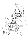
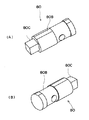
液晶パネル925R、925G、925Bは、図10に示されるように、クロスダイクロイックプリズム910の光入射面となる3側面と対向配置され、クロスダイクロイックプリズム910の対向する面(光入射面)に固定部材であるピン80並びに保持枠80Dを介して接着固定されている。ピン80は、図11に示されるように、円柱形状の挿入部80Bと、挿入時に外部に露出する角柱状の露出部80Cとを備えて構成されている。各液晶パネル925R、925G、925Bは、保持枠80Dによって保持されている。保持枠80Dの四隅には、孔80Aが設けられている。この孔80Aに、挿入部80Bに接着剤を塗布したピン80を挿入し、液晶パネル925R、925G、925Bの位置調整をした後、接着剤を固定することによって、液晶パネル925R、925G、925Bがプリズム910の側面に固定される。
【0056】
クロスダイクロイックプリズム910は、3色の色光を合成してカラー画像を形成する機能を有し、下ライトガイド902の上面に固定ネジにより固定されている。クロスダイクロイックプリズム910には、赤光を反射する誘電体多層膜と、青光を反射する誘電体多層膜とが、4つの直角プリズムの界面に沿って略X字状に形成され、これらの誘電体多層膜によって3つの色光が合成される。
【0057】
投写レンズ6は、プロジェクタ1の中でも最も重量の大きい光学部品であり、その基端側に設けられたフランジ62を介して下ライトガイド902のヘッド板903にネジ等で固定されている。
【0058】
以上のように構成された光学ユニット10は、以下のようにして組み立てられる。
【0059】
先ず、箱状の上ライトガイド901をその開口側が上向きとなるようにして置き、この上ライトガイド901内に照明光学系923、色光分離光学系924、およびリレー光学系927などを構成する各光学部品(反射ミラー、各種のレンズ等)を配置し、それらの光学部品をクリップ7で上ライトガイド901に固定する。
【0060】
一方、蓋状の下ライトガイド902においては、その上面に液晶パネル925R、925G、925Bを固定したクロスダイクロイックプリズム910を固定し、ヘッド板903に投写レンズ6を固定しておく。次いで、各光学部品が搭載された上ライトガイド901を持って反転させ、下ライトガイド902に被せるようにして取り付け、固定する。
【0061】
最後に、このようにして完成したライトガイド900を、ロアーケース4にネジ等で固定する。
【0062】
なお、液晶パネル925R、925G、925B、クロスダイクロイックプリズム910、および投写レンズ6を搭載しておいた下ライトガイド902を先にロアーケース4に固定しておき、その後、各光学部品が搭載された上ライトガイド901を持って反転させ、下ライトガイド902に被せるようにして取り付け、しかる後、ネジ等によって、上ライトガイド901をロアーケース4に固定するようにしてもよい。
【0063】
さらに、下ライトガイド902のみを先にロアーケース4にネジ止めしておき、そこに液晶パネル925R、925G、925Bおよびクロスダイクロイックプリズム910を搭載したり、投写レンズ6を固定したりし、その後、各光学部品が搭載された上ライトガイド901を持って反転させ、下ライトガイド902に被せるようにして取り付け、しかる後、ネジ等によって、上ライトガイド901をロアーケース4に固定するようにしてもよい。
【0064】
また、本実施形態において、下ライトガイド902へのクロスダイクロイックプリズム910や投写レンズ6の固定、ロアーケース4への上下ライトガイド901、902の固定は、ネジによって行われているが、そのような固定を接着や嵌合形式など、他の適宜な固定方法で行ってもよい。
【0065】
(5)光学系の機能
図9に示す光学ユニット10において、光源装置183から出射された略平行な光束は、インテグレータ光学系(照明光学系923)を構成する第1と第2のレンズアレイ921、922によって、複数の部分光束に分割される。第1のレンズアレイ921の各小レンズ9211から出射された部分光束は、重畳レンズ932によって、液晶パネル925R、925G、925Bの画像形成領域上で概ね重畳される。その結果、各液晶パネル925R、925G、925Bは、面内分布がほぼ均一な照明光によって照明される。
【0066】
この際、色光分離光学系924の第1のダイクロイックミラー941では、照明光学系923から出射された光束の赤色光成分が反射するとともに、青色光成分と緑色光成分とが透過する。第1のダイクロイックミラー941によって反射した赤色光は、反射ミラー943で反射し、フィールドレンズ951を通って赤色用の液晶パネル925Rに達する。このフィールドレンズ951は、第2のレンズアレイ922から出射された各部分光束をその中心軸(主光線)に対して平行な光束に変換する。他の液晶パネル925G、925Bの前に設けられたフィールドレンズ952、953も同様である。
【0067】
第1のダイクロイックミラー941を透過した青色光と緑色光のうちで、緑色光は第2のダイクロイックミラー942によって反射し、フィールドレンズ952を通って緑色用の液晶パネル925Gに達する。一方、青色光は第2のダイクロイックミラー942を透過してリレー光学系927を通り、さらにフィールドレンズ953を通って青色光用の液晶パネル925Bに達する。なお、青色光にリレー光学系927が用いられているのは、青色光の光路の長さが他の色光の光路長さよりも長いため、光の拡散等による光の利用効率の低下を防止するためである。すなわち、入射側レンズ954に入射した部分光束をそのまま、フィールドレンズ953に伝えるためである。
【0068】
赤、緑、青の各色光は、液晶パネル925R、925G、925Bに入射するにあたり、入射側偏光板960R、960G、960Bで特定の偏光光のみとされる。この後、各偏光光は、各液晶パネル925R、925G、925Bにおいて与えられた画像情報に従って変調され、変調光として出射側偏光板961R、961G、961Bに出射される。そして、出射側偏光板961R、961G、961Bにおいては、変調光のうちの特定の偏光光のみが透過し、クロスダイクロイックプリズム910に出射される。出射された各色光の偏光光は、クロスダイクロイックプリズム910で合成されて合成光となり、投写レンズ6の方向に出射される。この合成光は、投写レンズ6により投写スクリーン等の投写面上にカラー画像として投射される。
【0069】
(6)クロスダイクロイックプリズム910の取付構造
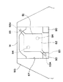
クロスダイクロイックプリズム910は、当該クロスダイクロイックプリズム910を支持する支持部材81を介して、下ライトガイド902上に載置・固定されている。支持部材81は、図10および図12に示されるように、クロスダイクロイックプリズム910が載置固定される載置部82と、この載置部82を下ライトガイド902に固定するための固定部83とを備えている。載置部82は、4つの角部を有し、クロスダイクロイックプリズム910の底面と略同じ大きさの平面略四角形状に形成され、クロスダイクロイックプリズム910下面に接着剤を介して取り付けられている。固定部83は、略矩形状に形成され、載置部82の周縁で、かつ、プリズム910の側面の外側に設けられている。また、固定部83は、載置部82の4つの角部のうち、対角線上の一対の角部に設けられている。この固定部83には、ネジ86が挿通される挿通孔83Aが形成されているとともに、下ライトガイド902の挿通孔83Aに対応した位置には、挿通孔83Aに挿通された前述のネジ86が螺合するネジ孔85が形成されている。
【0070】
一方、この支持部材81が載置固定される下ライトガイド902には、2つの円柱状の受部84が形成されている。詳しくは、図12に示されるように、受部84は、下ライトガイド902に載置部82を載置した際、当該載置部82の固定部83が設けられていない対角線上に当接する位置に形成されている。これにより、載置部82の下面を、固定部83が設けられていない対角線上で支持可能となっている。また、図12では、図示を略したが、下ライトガイド902には、クロスダイクロイックプリズム910の平面方向位置を規定する孔が形成され、載置部82の下面に形成された突起と係合することにより、下ライトガイド902上の所定位置にクロスダイクロイックプリズム910を配置できるようになっている。
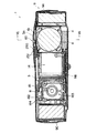
【0071】
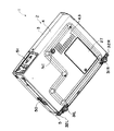
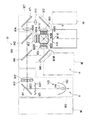
また、液晶パネル925R、925G、925B、およびクロスダイクロイックプリズム910は、図13および図14に示されるように、上ライトガイド901に平面視で凹状に形成された凹部87に配置されている。この凹部87の平面視内側には、吸気ファン17を固定するためのファン取付部90、91が設けられている。ファン取付部90は、吸気ファン17をネジ止め固定するためのものであり、四角板状に形成され、凹部87の液晶パネル925G側の2つの入隅部に設けられている。また、ファン取付部91は、両端に吸気ファン17に嵌合される2つの嵌合部92を有して長尺状に形成され、凹部87の投写レンズ6側の開口部分に跨って設けられている。ここで、前述の固定部83は、図14に示されるように、これらファン取付部90、91で被覆されている。このため、凹部87の上方から固定部83に挿通されているネジを取り外そうとしても、ファン取付部90、91で邪魔されて、取り外しができないようになっている。つまり、ファン取付部90、91は、固定部83を平面視で隠蔽被覆する被覆部を兼用するように構成されている。
【0072】
このような本実施形態によれば、次のような効果が得られる。
【0073】
すなわち、固定部83を、載置部82の周縁で、かつ、前記プリズムの側面の外側に設けたので、載置部82にネジ孔等の固定手段を形成する程度の肉厚が不要となる。従って、載置部82の肉厚を薄くすることができるので、全体的にプロジェクタ1の高さ寸法を小さくすることができる。これにより、プロジェクタ1の薄型化・小型化を図ることができる。また、ヘッド板903を含む構造体が下ライトガイド902と兼用され、下ライトガイド902に挿通孔83Aに対応したネジ孔85を形成したので、固定部83側からネジ86を挿通し、下ライトガイド902のネジ孔85に螺合することができる。これにより、従来の構造に比べて、プロジェクタ1の製造作業を容易に行うことができる。
【0074】
また、固定部83を、載置部82の対角線上の一対の角部に設けたので、載置部82をバランスよく下ライトガイド902に固定することができるとともに、外力が加わってもずれることがない。
【0075】
さらに、下ライトガイド902に受部84を形成したので、直交する対角線上の4カ所で載置部82を、下ライトガイド902に支持および固定することができ、支持部材81の固定をより一層強固にすることができる。
【0076】
また、上ライトガイド901の凹部87の平面視内側に、固定部83を平面視で隠蔽被覆する被覆部を形成し、当該固定部83を被覆部で隠したので、プロジェクタ1内部を露出させ、固定部83に挿通するネジ86を外そうとしても、被覆部が邪魔をして当該ネジ86を外すことが不可能となる。これにより、調整後のプロジェクタ1の画質劣化を未然に防止することができる。
【0077】
さらに、ファン取付部90、91に、被覆部を兼用させたので、別途被覆部をプロジェクタ1内部に設ける必要がなく、構造の簡素化を図ることができる。これにより、プロジェクタ1の組立作業を容易にできる。
【0078】
なお、本発明は前記実施の形態に限定されるものではなく、本発明の目的を達成できる他の構成等を含み、以下に示すような変形等も本発明に含まれる。
【0079】
例えば、前記実施形態では、ファン取付部90、91に被覆部を兼用させていたが、これに限らず、例えば、プロジェクタ1内部に別途被覆部を設けてもよい。
【0080】
また、前記実施形態では、被覆部を設けていたが、これに限らず、例えば、固定部を接着剤で固定し、一度固定したら、取り外すことができないようになっていれば、設けなくてもよい。
【0081】
さらに、前記実施形態では、下ライトガイド902に受部84を形成していたが、これに限らず、例えば、支持部材81が下ライトガイド902に強固に固定され、大きな外力が加わってもずれることがなければ、形成しなくてもよい。
【0082】
また、前記実施形態では、ヘッド板903および下ライトガイド902が一体化された構造であったが、これに限らず、例えば、ヘッド板とクロスダイクロイックプリズムの載置面とを備えた側面略L字状のヘッド体に本発明を利用してもよい。このようにすれば、前記実施形態と同様の作用効果を得ることができるうえ、ヘッド体の取り扱いが簡単なので、プロジェクタの製造作業をより一層容易にできる。
【0083】
また、前記実施形態では、固定部83は、載置部82の対角線上の一対の角部に設けていたが、これに限らず、例えば、隣り合う角部に設けてもよいし、対向する辺に設けてもよく、要するに、載置部82の周縁に設けられ、確実に固定できればよく、固定部の位置は実施に当たって適宜決めればよい。
【0084】
さらに、載置部としては、平面四角形状に限らず、例えば、平面円形状や平面三角形状のものも採用できる。
【0085】
また、固定部としては、挿通孔を形成したものに限らず、例えば、下ライトガイドに係合する係合部材が形成されたもの等が採用できる。
【0086】
また、前記実施形態では、2種類の誘電体多層膜が4つの直角プリズムの界面に沿って略X字状に形成されたクロスダイクロイックプリズムを用いていたが、クロスダイクロイックプリズムの代わりに、3つの異なる形状のプリズムの界面に沿って2種類の誘電体多層膜が形成されたプリズムを用いても良い。
【0087】
さらに、前記実施形態では、変調系925は、3枚の液晶パネル925R、925G、925Bから構成されていたが、これに限らず、2枚、あるいは4枚以上の液晶パネルから構成される光変調装置に本発明を採用してもよい。
【0088】
そして、前記実施形態では、光変調装置として液晶パネルを用いていたが、液晶以外のプラズマ素子や、マイクロミラーを用いたデバイスを用いたプロジェクタに本発明を採用してもよい。
【0089】
また、前記実施形態における光変調装置925R、925G、925Bは、光束R、G、Bを透過して変調する形式のものであったが、これに限らず、入射した光を反射しつつ変調して出射する反射型の光変調装置を備えたプロジェクタに本発明を採用してもよい。
【0090】
【発明の効果】
以上に述べたように、本発明のプロジェクタによれば、載置部を光学部品用筐体に固定するための固定部を、当該載置部の周縁に設けたので、載置部にネジ孔等の固定手段を形成する程度の肉厚が不要となり、載置部の肉厚を薄くでき、全体的にプロジェクタの高さ寸法を小さくすることができ、プロジェクタの薄型化・小型化を図ることができるという効果がある。
【図面の簡単な説明】
【図1】本発明の一実施形態に係るプロジェクタの上面側からの外観斜視図である。
【図2】前記実施形態におけるプロジェクタの下面側からの外観斜視図である。
【図3】前記実施形態におけるプロジェクタの内部構造を示す斜視図である。
【図4】前記実施形態におけるプロジェクタの光学系を示す斜視図である。
【図5】前記実施形態における光学系の構造を示す斜視図である。
【図6】前記実施形態における光学系の構造を示す他の斜視図である。
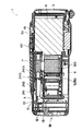
【図7】図1におけるVII−VII線に沿った断面図であり、前記プロジェクタの垂直断面図である。
【図8】図7におけるVIII−VIII線に沿った断面図であり、前記プロジェクタの別の垂直断面図である。
【図9】前記実施形態における光学系の機能を説明するための模式図である。
【図10】前記実施形態における液晶パネルおよびクロスダイクロイックプリズムの取付構造を示す分解斜視図である。
【図11】前記実施形態における液晶パネルをクロスダイクロイックプリズムに固定するためのピンを示す斜視図である。
【図12】前記実施形態における支持部材の取付構造を示す概略平面図である。
【図13】前記実施形態におけるプロジェクタの内部構造を示す分解斜視図である。
【図14】前記実施形態における支持部材の配置構造を示す概略平面図である。
【符号の説明】
1 プロジェクタ
17 冷却ファンである吸気ファン
81 支持部材
82 載置部
83 固定部
84 受部
87 凹部
90、91 ファン取付部
901 上ライトガイド
902 下ライトガイド
910 クロスダイクロイックプリズム
925 変調系
925R、925G、925B 液晶パネル[0001]
BACKGROUND OF THE INVENTION
The present invention provides a plurality of light modulation devices that modulate a plurality of color lights in accordance with image information, a prism that combines modulated light beams modulated by the plurality of light modulation devices, and an optical component housing to which the prisms are fixed. The present invention relates to a projector having a body.
[0002]
[Background]
Conventionally, three optical modulators that modulate three colors of light according to image information and an optical component that houses optical components such as a cross dichroic prism, lens, and mirror that synthesizes a modulated light beam modulated by the optical modulator. A projector is known that includes upper and lower light guides that are component housings and a projection lens that enlarges and projects a projection light beam synthesized by a prism.
[0003]
Such projectors are widely used for multimedia presentations at conferences, academic conferences, exhibitions, etc., and may be brought in as needed or moved to other locations after storage, so they are thinner and smaller. Is being promoted.
[0004]
Here, in the projector using the three light modulation devices as described above, the cross dichroic prism is usually housed in a recess formed in the light guide and attached to a structure to which the projection lens is attached. Conventionally, a screw is inserted into the lower surface of the structure and attached by screwing into a screw hole formed in a support member on the lower surface of the prism.
[0005]
[Problems to be solved by the invention]
However, in such a conventional projector, it is necessary to increase the thickness of the support member so as to ensure a sufficient depth of the screw hole into which the screw is screwed. There is a problem that the projector cannot be reduced in thickness and size by reducing the overall height of the projector.
[0006]
An object of the present invention is to provide a projector that can be reduced in thickness and size.
[0007]
[Means for Solving the Problems]
The present invention provides a plurality of light modulation devices that modulate a plurality of color lights in accordance with image information, a prism that combines modulated light beams modulated by the plurality of light modulation devices, and an optical component housing to which the prisms are fixed. The prism is fixed to the optical component casing via a support member that supports the prism, and the support member is a mounting unit on which the prism is mounted and fixed. And a fixing part for fixing the mounting part to the optical component casing, the fixing part being provided at the periphery of the mounting part and outside the side surface of the prism, The optical component casing is formed in a concave shape in a plan view, and a concave portion in which the plurality of light modulation devices and the prism are arranged is formed. The inner side of the concave portion includes the optical component casing in the optical component casing. The part where the fixing part is fixed On the opposite side, wherein the covering portion for concealing cover the fixing portion in a plan view are formed.
[0008]
Here, as the fixing portion, a member in which an insertion hole for inserting a screw or an engagement member that engages with the optical component casing can be employed.
[0009]
According to the present invention, the mounting portion is provided on the periphery of the mounting portion and on the outer side of the side surface of the prism by fixing the mounting portion to the optical component housing. Therefore, a thickness sufficient to form a fixing means such as a screw hole is not required. Therefore, since the thickness of the mounting portion can be reduced, the overall height of the projector can be reduced. This makes it possible to reduce the thickness and size of the projector.
[0010]
In addition, since the fixing portion for fixing the mounting portion to the optical component housing is provided on the periphery of the mounting portion and outside the side surface of the prism, for example, a screw is inserted into the fixing portion. If a screw hole corresponding to the insertion hole is formed on the optical component housing side, a screw is inserted from the prism mounting surface side and screwed into the screw hole of the optical component housing. It becomes possible to do. Thereby, the manufacturing work of the projector becomes easier as compared with the conventional structure in which the screw has to be inserted from the side opposite to the prism mounting surface.
The prism and the plurality of light modulation devices are fixed in a state in which the plurality of images are adjusted to be projected in the focused state at the same position on the projection screen. However, for example, if the user moves the prism after performing such adjustment, the positions of the prism and the plurality of light modulation devices are shifted, and the image projected on the screen or the like is disturbed. There is a fear.
Therefore, if the covering portion for concealing and covering the fixing portion in plan view is formed on the optical component casing, and the fixing portion is hidden by the covering portion, it becomes impossible to touch the fixing portion from the outside. As a result, it is possible to prevent image quality deterioration of the adjusted projector.
[0011]
In the above, the mounting part is formed in a substantially rectangular shape having four corners, and the fixing part is provided at a pair of diagonal corners among the four corners of the mounting part. Preferably it is.
[0012]
In this way, it is possible to fix the mounting portion to the optical component casing in a well-balanced manner, and there is no deviation even when an external force is applied.
[0013]
Moreover, it is desirable that the above-described optical component housing has a receiving portion that supports the lower surface of the mounting portion on a diagonal line where no fixing portion is provided.
[0014]
With this configuration, the mounting portion is supported and fixed to the optical component casing at four positions on the orthogonal diagonal lines, so that the support member can be more firmly fixed.
[0018]
Further, the above-described optical component housing has a fan mounting portion to which a cooling fan for cooling a plurality of light modulation devices is fixed, and this fan mounting portion preferably also serves as a covering portion. .
[0019]
In this way, since it is not necessary to provide a separate coating portion inside the apparatus, the structure can be simplified. This facilitates the assembly work of the projector.
[0020]
DETAILED DESCRIPTION OF THE INVENTION
Embodiments of the present invention will be described below with reference to the drawings.
[0021]
(1) Overall configuration of the device
1 and 2 are schematic perspective views of the
[0022]
The
[0023]
(2) Exterior case structure
The
[0024]
An
[0025]
In addition, on the upper surface of the
[0026]
In FIG. 2, a
[0027]
A
[0028]
An
[0029]
(3) Internal structure of the device
3 to 8 show the internal structure of the
[0030]
In these drawings, a light
[0031]
The
[0032]
The first
[0033]
The second power supply block 9B transforms the electric power obtained from the first
[0034]
The third
[0035]
Such first to third power supply blocks 9A to 9C are fixed to the
[0036]
The light
[0037]
The
[0038]
In the
[0039]
The
[0040]
The cross
[0041]
The driver board 11 is for controlling the
[0042]
The
[0043]
The
[0044]
In the above internal structure, the cooling air sucked by the
[0045]
(4) Structure of optical system
Next, the
[0046]
The
[0047]
The illumination
[0048]
A
[0049]
The
[0050]
The
[0051]
The
[0052]
The color light separation
[0053]
The relay
[0054]
The
[0055]
As shown in FIG. 10, the
[0056]
The cross
[0057]
The
[0058]
The
[0059]
First, a box-shaped upper
[0060]
On the other hand, in the lid-shaped lower
[0061]
Finally, the completed
[0062]
The lower
[0063]
Further, only the lower
[0064]
In this embodiment, the cross
[0065]
(5) Optical system functions
In the
[0066]
At this time, the first
[0067]
Of the blue light and green light transmitted through the first
[0068]
The red, green, and blue color lights are incident on the
[0069]
(6) Mounting structure of the cross
The cross
[0070]
On the other hand, two
[0071]
Further, the
[0072]
According to this embodiment, the following effects can be obtained.
[0073]
That is, since the fixing
[0074]
In addition, since the fixing
[0075]
Further, since the receiving
[0076]
In addition, a covering portion that covers and covers the fixing
[0077]
Further, since the
[0078]
In addition, this invention is not limited to the said embodiment, Other structures etc. which can achieve the objective of this invention are included, The deformation | transformation etc. which are shown below are also contained in this invention.
[0079]
For example, in the embodiment described above, the
[0080]
Moreover, in the said embodiment, although the coating | coated part was provided, it is not restricted to this, For example, if a fixing | fixed part is fixed with an adhesive and once fixed, if it becomes impossible to remove, it does not need to provide. Good.
[0081]
Furthermore, in the above-described embodiment, the receiving
[0082]
In the above embodiment, the
[0083]
Moreover, in the said embodiment, although the fixing | fixed
[0084]
Furthermore, the mounting portion is not limited to a planar square shape, and for example, a planar circular shape or a planar triangular shape can also be employed.
[0085]
Moreover, as a fixing | fixed part, not only what formed the insertion hole but the thing etc. in which the engaging member engaged with a lower light guide was formed, for example can be employ | adopted.
[0086]
In the above embodiment, a cross dichroic prism in which two types of dielectric multilayer films are formed in a substantially X shape along the interface of four right-angle prisms is used. You may use the prism in which two types of dielectric multilayer films were formed along the interface of the prism of a different shape.
[0087]
Furthermore, in the above-described embodiment, the
[0088]
In the embodiment, the liquid crystal panel is used as the light modulation device. However, the invention may be applied to a projector using a plasma element other than liquid crystal or a device using a micromirror.
[0089]
In addition, the
[0090]
【The invention's effect】
As described above, according to the projector of the present invention, the fixing portion for fixing the mounting portion to the optical component casing is provided on the periphery of the mounting portion. It is not necessary to have a thickness that can be used to form a fixing means such as, so that the thickness of the mounting portion can be reduced, the height of the projector can be reduced overall, and the projector can be made thinner and smaller. There is an effect that can be.
[Brief description of the drawings]
FIG. 1 is an external perspective view from the upper surface side of a projector according to an embodiment of the invention.
FIG. 2 is an external perspective view from the lower surface side of the projector in the embodiment.
FIG. 3 is a perspective view showing an internal structure of the projector in the embodiment.
FIG. 4 is a perspective view showing an optical system of the projector in the embodiment.
FIG. 5 is a perspective view showing a structure of an optical system in the embodiment.
FIG. 6 is another perspective view showing the structure of the optical system in the embodiment.
7 is a sectional view taken along line VII-VII in FIG. 1, and is a vertical sectional view of the projector.
FIG. 8 is a cross-sectional view taken along line VIII-VIII in FIG. 7, and is another vertical cross-sectional view of the projector.
FIG. 9 is a schematic diagram for explaining the function of the optical system in the embodiment.
FIG. 10 is an exploded perspective view showing a mounting structure of a liquid crystal panel and a cross dichroic prism in the embodiment.
11 is a perspective view showing pins for fixing the liquid crystal panel to the cross dichroic prism in the embodiment. FIG.
12 is a schematic plan view showing a mounting structure of a support member in the embodiment. FIG.
FIG. 13 is an exploded perspective view showing the internal structure of the projector in the embodiment.
FIG. 14 is a schematic plan view showing an arrangement structure of support members in the embodiment.
[Explanation of symbols]
1 Projector
17 Intake fan that is a cooling fan
81 Support member
82 Placement part
83 Fixed part
84 Receiver
87 recess
90, 91 Fan mounting part
901 Upper light guide
902 Lower light guide
910 Cross Dichroic Prism
925 modulation system
925R, 925G, 925B LCD panel
Claims (4)
前記プリズムは、当該プリズムを支持する支持部材を介して前記光学部品用筐体に固定され、
前記支持部材は、前記プリズムが載置固定される載置部と、この載置部を前記光学部品用筐体に固定するための固定部とを備え、
前記固定部は、前記載置部の周縁で、かつ、前記プリズムの側面よりも外側に設けられ、
前記光学部品用筐体には、平面視で凹状に形成され、前記複数の光変調装置およびプリズムを内部に配置する凹部が形成され、
前記凹部の内側には、前記光学部品用筐体における前記固定部が固定される部位とは反対側に、平面視で前記固定部を隠蔽被覆する被覆部が形成されていることを特徴とするプロジェクタ。A plurality of light modulation devices that modulate a plurality of color lights according to image information, a prism that combines modulated light beams modulated by the plurality of light modulation devices, and an optical component housing to which the prisms are fixed. Projector,
The prism is fixed to the optical component housing via a support member that supports the prism,
The support member includes a placement portion on which the prism is placed and fixed, and a fixing portion for fixing the placement portion to the optical component casing,
The fixing portion is provided at the periphery of the mounting portion and outside the side surface of the prism,
The optical component casing is formed in a concave shape in a plan view, and a concave portion in which the plurality of light modulation devices and the prism are disposed is formed.
A covering portion that covers and covers the fixing portion in plan view is formed on the inner side of the concave portion on a side opposite to a portion where the fixing portion is fixed in the optical component casing. projector.
前記載置部は、4つの角部を有する平面略四角形状に形成され、
前記固定部は、前記載置部の4つの角部のうち、対角線上の一対の角部に設けられていることを特徴とするプロジェクタ。The projector according to claim 1, wherein
The mounting portion is formed in a substantially rectangular shape having four corners,
The fixing unit is provided with a pair of corners on a diagonal line among the four corners of the mounting unit.
前記光学部品用筐体には、前記固定部が設けられていない対角線上で前記載置部の下面を支持する受部が形成されていることを特徴とするプロジェクタ。The projector according to claim 2,
The projector for an optical component, wherein a receiving portion that supports a lower surface of the mounting portion on a diagonal line where the fixing portion is not provided is formed.
前記光学部品用筐体は、前記複数の光変調装置を冷却するための冷却ファンが固定されるファン取付部を有し、このファン取付部は、前記被覆部を兼用していることを特徴とするプロジェクタ。The projector according to any one of claims 1 to 3,
The optical component housing includes a fan mounting portion to which a cooling fan for cooling the plurality of light modulation devices is fixed, and the fan mounting portion also serves as the covering portion. Projector.
Priority Applications (2)
| Application Number | Priority Date | Filing Date | Title |
|---|---|---|---|
| JP33349799A JP3772614B2 (en) | 1999-11-24 | 1999-11-24 | projector |
| US09/716,385 US6491399B1 (en) | 1999-11-24 | 2000-11-21 | Projector |
Applications Claiming Priority (1)
| Application Number | Priority Date | Filing Date | Title |
|---|---|---|---|
| JP33349799A JP3772614B2 (en) | 1999-11-24 | 1999-11-24 | projector |
Publications (2)
| Publication Number | Publication Date |
|---|---|
| JP2001154272A JP2001154272A (en) | 2001-06-08 |
| JP3772614B2 true JP3772614B2 (en) | 2006-05-10 |
Family
ID=18266728
Family Applications (1)
| Application Number | Title | Priority Date | Filing Date |
|---|---|---|---|
| JP33349799A Expired - Fee Related JP3772614B2 (en) | 1999-11-24 | 1999-11-24 | projector |
Country Status (2)
| Country | Link |
|---|---|
| US (1) | US6491399B1 (en) |
| JP (1) | JP3772614B2 (en) |
Families Citing this family (14)
| Publication number | Priority date | Publication date | Assignee | Title |
|---|---|---|---|---|
| JP3888040B2 (en) * | 2000-07-10 | 2007-02-28 | セイコーエプソン株式会社 | Optical component and projector equipped with the same |
| CA100412S (en) | 2002-03-01 | 2003-06-03 | Fujitsu General Ltd | Liquid crystal projector |
| USD481056S1 (en) | 2002-03-28 | 2003-10-21 | Seiko Epson Corporation | Control panel for projector |
| USD479261S1 (en) | 2002-03-28 | 2003-09-02 | Seiko Epson Corporation | Projector |
| USD476024S1 (en) | 2002-04-09 | 2003-06-17 | Sharp Kabushiki Kaisha | Video projector |
| CA100929S (en) | 2002-06-11 | 2004-02-09 | Toshiba A T A Toshiba Corp Kk | Liquid crystal projector |
| CA100927S (en) | 2002-06-26 | 2004-02-09 | Toshiba A T A Toshiba Corp Kk | Liquid crystal projector |
| USD480409S1 (en) | 2002-11-07 | 2003-10-07 | Benq Corporation | Projector |
| USD499753S1 (en) | 2003-05-29 | 2004-12-14 | Casio Keisanki Kabushiki Kaisha | Projector |
| USD498249S1 (en) | 2003-05-29 | 2004-11-09 | Casio Keisanki Kabushiki Kaisha | Projector |
| USD520551S1 (en) * | 2003-06-02 | 2006-05-09 | Infocus Corporation | Projection device |
| USD539326S1 (en) | 2004-08-16 | 2007-03-27 | Infocus Corporation | Projection device |
| JP4939779B2 (en) * | 2005-08-09 | 2012-05-30 | 株式会社日立製作所 | Projection-type image display device |
| JP5664979B2 (en) * | 2011-11-04 | 2015-02-04 | 株式会社リコー | Image projection device |
Family Cites Families (1)
| Publication number | Priority date | Publication date | Assignee | Title |
|---|---|---|---|---|
| JP3454152B2 (en) * | 1998-06-22 | 2003-10-06 | セイコーエプソン株式会社 | Projection display device |
-
1999
- 1999-11-24 JP JP33349799A patent/JP3772614B2/en not_active Expired - Fee Related
-
2000
- 2000-11-21 US US09/716,385 patent/US6491399B1/en not_active Expired - Lifetime
Also Published As
| Publication number | Publication date |
|---|---|
| US6491399B1 (en) | 2002-12-10 |
| JP2001154272A (en) | 2001-06-08 |
Similar Documents
| Publication | Publication Date | Title |
|---|---|---|
| JP3888045B2 (en) | Projection display | |
| JP3606094B2 (en) | Projection display | |
| JP3438682B2 (en) | projector | |
| US7564505B2 (en) | Optical device and projector equipped with the same | |
| JP3888040B2 (en) | Optical component and projector equipped with the same | |
| JP3772614B2 (en) | projector | |
| JP4023314B2 (en) | Optical component casing, optical device, and projector | |
| JP3606105B2 (en) | Projection display | |
| JP2000241884A (en) | Projection display device | |
| JP2001066699A (en) | projector | |
| US7611248B2 (en) | Projection lens unit and thin projector using the same | |
| US7997741B2 (en) | Projector | |
| JP2002148606A (en) | LCD projector | |
| US6139155A (en) | Projector display device | |
| US6456012B1 (en) | Projector | |
| JP3367491B2 (en) | Electro-optical device attachment unit and projector using the same | |
| JP2001021987A (en) | Projection display device | |
| JP2001021990A (en) | Projection display device | |
| JP3567743B2 (en) | Projection display device | |
| JP3613070B2 (en) | Enclosure for optical parts and projection display device using the same | |
| JP3603647B2 (en) | Projection display device | |
| JP2001201794A (en) | projector | |
| JP3800935B2 (en) | projector | |
| JP3692781B2 (en) | Projection display | |
| JP2001033876A (en) | Light source device and projection display device using the same |
Legal Events
| Date | Code | Title | Description |
|---|---|---|---|
| A521 | Written amendment |
Free format text: JAPANESE INTERMEDIATE CODE: A821 Effective date: 20040312 |
|
| A621 | Written request for application examination |
Free format text: JAPANESE INTERMEDIATE CODE: A621 Effective date: 20040312 |
|
| RD02 | Notification of acceptance of power of attorney |
Free format text: JAPANESE INTERMEDIATE CODE: A7422 Effective date: 20040312 |
|
| A977 | Report on retrieval |
Free format text: JAPANESE INTERMEDIATE CODE: A971007 Effective date: 20051101 |
|
| A131 | Notification of reasons for refusal |
Free format text: JAPANESE INTERMEDIATE CODE: A131 Effective date: 20051115 |
|
| A521 | Written amendment |
Free format text: JAPANESE INTERMEDIATE CODE: A523 Effective date: 20051227 |
|
| TRDD | Decision of grant or rejection written | ||
| A01 | Written decision to grant a patent or to grant a registration (utility model) |
Free format text: JAPANESE INTERMEDIATE CODE: A01 Effective date: 20060124 |
|
| A61 | First payment of annual fees (during grant procedure) |
Free format text: JAPANESE INTERMEDIATE CODE: A61 Effective date: 20060206 |
|
| R150 | Certificate of patent or registration of utility model |
Free format text: JAPANESE INTERMEDIATE CODE: R150 |
|
| FPAY | Renewal fee payment (event date is renewal date of database) |
Free format text: PAYMENT UNTIL: 20090224 Year of fee payment: 3 |
|
| FPAY | Renewal fee payment (event date is renewal date of database) |
Free format text: PAYMENT UNTIL: 20100224 Year of fee payment: 4 |
|
| FPAY | Renewal fee payment (event date is renewal date of database) |
Free format text: PAYMENT UNTIL: 20110224 Year of fee payment: 5 |
|
| FPAY | Renewal fee payment (event date is renewal date of database) |
Free format text: PAYMENT UNTIL: 20110224 Year of fee payment: 5 |
|
| FPAY | Renewal fee payment (event date is renewal date of database) |
Free format text: PAYMENT UNTIL: 20120224 Year of fee payment: 6 |
|
| FPAY | Renewal fee payment (event date is renewal date of database) |
Free format text: PAYMENT UNTIL: 20130224 Year of fee payment: 7 |
|
| FPAY | Renewal fee payment (event date is renewal date of database) |
Free format text: PAYMENT UNTIL: 20130224 Year of fee payment: 7 |
|
| LAPS | Cancellation because of no payment of annual fees |