JP3768861B2 - Image processing method and apparatus, and printing apparatus - Google Patents
Image processing method and apparatus, and printing apparatus Download PDFInfo
- Publication number
- JP3768861B2 JP3768861B2 JP2001335187A JP2001335187A JP3768861B2 JP 3768861 B2 JP3768861 B2 JP 3768861B2 JP 2001335187 A JP2001335187 A JP 2001335187A JP 2001335187 A JP2001335187 A JP 2001335187A JP 3768861 B2 JP3768861 B2 JP 3768861B2
- Authority
- JP
- Japan
- Prior art keywords
- continuous still
- image
- still images
- image processing
- still image
- Prior art date
- Legal status (The legal status is an assumption and is not a legal conclusion. Google has not performed a legal analysis and makes no representation as to the accuracy of the status listed.)
- Expired - Fee Related
Links
Images


Description
【0001】
【発明の属する技術分野】
本発明は、動画データより得られる複数の画像をプリント出力させるための画像処理方法及び装置並びに印刷装置に関する。
【0002】
【従来の技術】
被写体の連続する動きを複数の画像としてプリントする装置が提案されている。この種の装置の例として、例えば、特開平10−327376号公報に記載されているものが挙げられる。
【0003】
特開平10−327376号公報によれば、撮影開始の指示から、予め設定された撮影時間が経過するまでの間のビデオカメラ出力より、所定枚数の撮像画像を得て記憶し、図25に示す如くプリントアウトすることが記載されている。このプリント出力には、各撮像画像の側方に余白部が設けられており、この余白部を綴じ代として利用して図26の(a)ように束ねることができる。ユーザはこうして束ねたプリントを図26の(b)のように連続的に捲ることで、撮像画像を動画的に観察することができる。以下、本明細書では、このような動画を「捲り動画」と称する。また、捲り動画を提供する連続的な静止画を連続静止画と称する。
【0004】
また、図25におけるプリント出力の余白部の位置は、撮像画像の左側或は右側の何れかを指定することができ、ユーザが右利きの場合と左利きの場合に対応できるようにしている。すなわち、余白部を撮像画像の左側に設けるように指定すれば、右利き用(左綴じ用)のプリントアウトを得ることができ、余白部を撮像画像の右側に設けるように指定すれば左利き用(右綴じ用)のプリントアウトを得ることができる。
【0005】
【発明が解決しようとする課題】
一般に、この種の装置では、撮影の開始から終了までの全範囲について、所定時間間隔で撮像画像を取り出し、連続静止画を出力するために記憶している。上記の特開平10−327376号公報によれば、8秒、10秒、12秒のうちの所望の撮影時間を指定すると、指定された撮影時間で撮影が行われ、その撮影の間に所定間隔で撮像画像が記憶される。例えば、8秒が指定されれば、48枚の撮像画像を記憶するべく1/6秒毎に撮像画像が記憶され、10秒が指定されれば、48枚の撮像画像を記憶するべく1/5秒毎に撮像画像が記憶される。
【0006】
しかしながら、例えば、10秒の撮影時間を指定したものの、ユーザにとって興味のある部分がそのうちの2秒から9秒の部分であった場合には、最初と最後の1秒に含まれる撮像画像は無駄なプリント出力となってしまう。また、特開2001−223876号公報にも、「動画として撮影し、その中から、一定時間間隔で個々のコマを切り出すようにしてもよい」と記載されているのみである。
【0007】
このように、従来技術においては、撮影された一連の動画全体を対象として画像の切り出しを行うのみであるため、ユーザの興味にきめ細かく対応したプリント出力を得ることはできないという課題がある。
【0008】
また、特開平10−327376号公報や特開2001−223876号公報においては、動画中の指定された所望の範囲を静止画の切り出し範囲として設定するという概念がないので、指定された所望の範囲が非常に短く、所定数の連続静止画像を生成できない場合については何等考慮がなされていない。
【0009】
本発明は、上記課題に鑑みてなされたものであり、動画中の所望の範囲から所定枚数の連続静止画を得ることによりユーザの要求にきめ細かく対応可能とするとともに、指定された所望範囲の広狭に関わらず所定枚数の連続静止画を取得可能とすることを目的とする。
【0010】
【課題を解決するための手段】
上記の目的を達成するための本発明による画像処理装置は以下の構成を備える。すなわち、
動画データに基づいて、捲り動画として観察が可能な複数の連続静止画像を印刷させるための画像処理装置であって、
前記動画データ中の範囲を指定する指定手段と、
前記動画データの前記指定手段で指定された範囲より予め定められた数のフレームを抽出可能か判定する判定手段と、
前記判定手段で抽出可能と判定された場合に、前記指定された範囲より前記予め定められた数のフレームを抽出して該予め定められた数の連続静止画を生成する第1生成手段と、
前記判定手段で抽出可能ではないと判定された場合に、前記指定された範囲より抽出可能な数のフレームを抽出して連続静止画を生成し、不足分を同一のフレームの繰り返し利用により補って、前記予め定められた数の連続静止画を生成する第2生成手段とを備える。
【0011】
また、上記の目的を達成するための本発明による画像処理方法は、
動画データに基づいて、捲り動画として観察が可能な複数の連続静止画像を印刷させるための画像処理方法であって、
前記動画データ中の範囲を指定する指定工程と、
前記動画データの前記指定工程で指定された範囲より予め定められた数のフレームを抽出可能か判定する判定工程と、
前記判定工程で抽出可能と判定された場合に、前記指定された範囲より前記予め定められた数のフレームを抽出して該予め定められた数の連続静止画を生成する第1生成工程と、
前記判定工程で抽出可能ではないと判定された場合に、前記指定された範囲より抽出可能な数のフレームを抽出して連続静止画を生成し、不足分を同一のフレームの繰り返し利用により補って、前記予め定められた数の連続静止画を生成する第2生成工程とを備える。
【0012】
更に、上記の目的を達成する本発明の印刷装置は、
動画データに基づいて、捲り動画として観察が可能な複数の連続静止画像を印刷する印刷装置であって、
前記動画データ中の範囲を指定する指定手段と、
前記動画データの前記指定手段で指定された範囲より予め定められた数のフレームを抽出可能か判定する判定手段と、
前記判定手段で抽出可能と判定された場合に、前記指定された範囲より予め定められた数のフレームを抽出して該予め定められた数の連続静止画を生成する第1生成手段と、
前記判定手段で抽出可能ではないと判定された場合に、前記指定された範囲より抽出可能な数のフレームを抽出して連続静止画を生成し、不足分を同一のフレームの繰り返し利用により補って、前記予め定められた数の連続静止画を生成する第2生成手段と、
前記第1もしくは第2生成手段で生成された前記予め定められた数の連続静止画を印刷する印刷手段とを備える。
【0013】
【発明の実施の形態】
以下、添付の図面を参照して、本発明の好適な実施形態を説明する。
【0014】
[システム構成]
図1は本実施形態による画像形成システムの構成を示すブロック図である。本実施形態における画像形成システムは、印刷データ(制御コマンドを含む)を生成する情報処理装置100と、その印刷データに基づいて画像を形成するプリンタ170とで構成される。
【0015】
情報処理装置100は、メモリ110、CPU130、ハードディスク・コントローラ(HDC)120とこれに接続されるハードディスク(HD)121、フレキシブルディスク・コントローラ(FDC)125とこれに接続されるフレキシブルディスクドライブ(FD)126、プリンタ・コントローラ(PRTC)140、キーボード/ポインティングデバイス・コントローラ(KB/PDC)150とこれに接続されるキーボード(KB)及びポインティングデバイス(PD)151、CRTコントローラ(CRTC)160とこれに接続されるCRT161を備える。
【0016】
なお、ポインティングデバイス(PD)として、本実施形態ではマウスを用いるが、トラックボールや、タッチパネル等、種々のデバイスを利用可能である。また、上記構成では、表示器としてCRT161を用いているが、液晶やプラズマディスプレイ等、他のタイプの表示器であってもよいことは言うまでもない。
【0017】
メモリ110は、例えば、本発明における画像編集の処理を司るアプリケーション111、プリンタ170に対応する印刷データを生成するためのソフトウェアであるプリンタドライバ112、プリンタ170に供給すべき印刷データをスプールするスプーラ領域113、その他不図示のOS(オペレーティングシステム)やワーク領域等を有する。
【0018】
CPU130は、メモリ110内のアプリケーション111、プリンタドライバ112、OS等に基づいて動作する。なお、電源投入時は不図示のROMに格納されたブートプログラムによりブートし、HD121からOSのプログラムをメモリ110にロードしてOSを起動する。以降、OSの管理の下で、アプリケーションプログラムが同様にロードされ、実行されることにより、画像形成システムとして機能する。また、当然のことながら、CPU130は、HDC120を介してHD121にアクセスすることができる。
【0019】
PRTC140は、スプーラ領域113に蓄えられた印刷データを順次プリンタ170に送信する処理を行なう。KB/PDC150は、KB/PD151を制御し、キーボードやマウスを用いて入力されるユーザからの指示データを装置内に取り込む。CRTC160は、表示装置であるCRT161を制御するコントローラである。これらのブロック150、151、160、161により、ユーザインターフェースが構成される。
【0020】
一方、プリンタ170には情報処理装置100から印刷データを受信するため、及び各種ステータスを情報処理装置100に通知するためのインターフェース171、主として受信したプリンタデータを解釈し、ビットマップイメージデータを発生するプリンタ制御部172、プリンタ制御部172から出力されてきたビットマップイメージデータを受け、実際に画像を形成するプリンタエンジン173で構成される。なお、図示してはいないが操作パネル等も具備している。また、プリンタエンジン173は、インクジェット方式、電子写真方式、感熱方式等、何れの方式を用いたものでもよい。
【0021】
なお、上記の構成において、情報処理装置100にプリンタ170を接続した際には、その最初の段階ではプリンタ170に対応するプリンタデータを生成するためのプリンタドライバをインストールする必要がある。言うまでもないが、このインストールは、格別の理由がない限りは、通常は一度行なえば事足りるものである。
【0022】
図2は、図1に示した画像形成システムの情報処理装置100を、ソフトウエア構成の観点から説明する図である。
【0023】
情報処理装置100には、入力装置としてキーボードやマウス(KB/PD)151が接続されている。また、出力装置として、プリンタ170とモニタとしてのCRT161が接続されている。
【0024】
キーボードやマウスを用いてなされた入力は、キーボード・マウスドライバ182により処理され、OS180に渡される。また、情報処理装置100は、ワードプロセッサ、表計算、インターネットブラウザなどのアプリケーションソフトウェア111を有する。アプリケーションソフトウェア111によって発行される出力画像を示す各種描画処理命令群(イメージ描画命令、テキスト描画命令およびグラフィクス描画命令)は、OS180を介してモニタドライバ181へ入力される。また、印刷を行う場合には、それら描画命令群はOS180を介してプリンタドライバ112へ入力される。プリンタドライバ112は描画命令群を処理して印刷データを作成してプリンタ170に印刷させるソフトウエアであり、モニタドライバ181はCRT161に画像を表示させるためのソフトウェアである。
【0025】
なお、図1、図2に示す情報処理装置100として、一般に普及しているIBM AT互換機のパーソナルコンピュータを使用し、OS180としてMicrosoft社の Windows98(R)を使用することが考えられる。また、そのようなパーソナルコンピュータに、モニタ161・プリンタ170およびキーボード・マウス151を接続し、以下で説明する印刷処理アプリケーションを実行させることで、本実施形態の印刷システムが実現される。
【0026】
情報処理装置100では、アプリケーションソフトウェア111により、文字などのテキストに分類されるテキストデータ、図形などのグラフィクスに分類されるグラフィクスデータ、写真画像などに分類されるイメージ画像データなどを用いて出力画像データが作成される。そして、この出力画像データに基づく画像を印刷する場合、アプリケーションソフトウェア111は、OS180に印刷出力要求を行うとともに、テキストデータ部分はテキスト描画命令、グラフィクスデータ部分はグラフィクス描画命令、イメージ画像データ部分はイメージ描画命令で構成される描画命令群をOS180に発行する。
【0027】
OS180はアプリケーションソフトウェア111から上記印刷出力要求を受けると、プリンタ170に対応するプリンタドライバ112に描画命令群を渡す。プリンタドライバ112はOS180から渡される印刷出力要求および描画命令群を処理して、プリンタ170が印刷処理可能な印刷データを作成し、その印刷データをプリンタ170に送る。
【0028】
なお、プリンタ170がラスタプリンタである場合、プリンタドライバ112は、描画命令群を、順次、例えばRGBそれぞれ8ビット深さをもつバンドメモリにラスタライズする。そして、全ての描画命令をラスタライズした後、ページメモリの内容をプリンタ170が印刷可能なデータ形式、例えばCMYKデータに変換してプリンタ170に送る。なお、このバンドメモリは例えばRAM(メモリ110)に割り当てられる。
【0029】
[印刷処理アプリケーションについて]
次に、上記アプリケーション111として動作可能な、本実施形態による印刷処理アプリケーションについて説明する。本実施形態の印刷処理アプリケーションは、動画データの所望範囲より所定数の連続静止画を抽出し、図23に示すような、短冊状シートに切り離しが可能なミシン目が設けられた用紙に、これら連続静止画を印刷する。短冊状シートの長手方向に連続静止画と余白部が並ぶようにして印刷することにより、各短冊状シートには綴じ代が形成される。こうして得られた短冊状シートを図18、図19に示す如く束ねることで、捲り動画を観察することが可能となる。以下、本実施形態の印刷処理アプリケーションの動作・機能について詳細に説明する。
【0030】
本実施形態の印刷処理アプリケーションを起動すると、専用のアプリケーションウインドウが表示される。アプリケーションウインドウとしては、用紙選択画面(図7参照)、動画選択画面(図8参照)、範囲設定画面(図9A参照)及び印刷・保存画面(図10A参照)が用意されている。なお、本印刷アプリケーションを起動した場合、初期画面として用紙選択ウインドウが表示されるものとするが、これに限定されるものではない。また、各画面には、画面選択のためのタブ(301a〜301d)が設けられており、所望のタブをクリックすることで図7〜図10Aの画面のうちの所望の画面に移行させることができる。
【0031】
本印刷処理アプリケーションによる概略の印刷手順は、以下のようになる。
・用紙選択画面において使用するプリンタや用紙等の設定を行ない、
・動画選択画面において所望の動画ファイルを選択し、
・範囲設定画面において、動画選択画面で選択された動画ファイル中の所望の範囲を設定するとともに、捲り動画のプレビューにより設定した範囲が適切であったか否かを確認し、
・印刷・保存画面において、上記範囲設定画面で設定された所望の範囲から所定数からなる連続静止画を生成し、これを上記設定されたプリンタにて出力させる。
【0032】
以下、各画面毎に動作の詳細を説明する。
【0033】
まず、図3、図7を参照して、用紙選択画面を表示して実行される用紙選択処理について説明する。図3は図7に示される用紙選択画面が選択された状態において実行される処理を説明するフローチャートである。
【0034】
ステップS101では、ボックス310に選択したいプリンタの名称を入力させ、ユーザにプリンタの選択を促す。ここで、ボックス310の左側の▽部分をクリックすると、利用可能なプリンタのリストが表示され、ユーザはその中から所望のプリンタを選択することができる。利用可能なプリンタが1台しかない場合は、そのプリンタがボックス310に表示される。なお、利用可能なプリンタとは、当該印刷アプリケーションが対応しているプリンタであり、当該情報処理装置にプリンタドライバがインストールされているものである。また、本アプリケーションの起動時においては、前回終了時に選択されていたプリンタを選択されたプリンタとする。
【0035】
ステップS102では、ボックス311を用いたカートリッジの選択が、ステップS103ではボックス312を用いた用紙の選択が行なわれる。なお、本実施形態では、用紙サイズをA4に固定しているが、所望の用紙サイズを選択できるようにしてもよい。
【0036】
ステップS104では別の画面へ移行するためのタブ(301b〜301dのいずれか)が選択されたかどうかを判定し、選択されていなければ処理をステップS101に戻す。また、別の画面へ移行するためのタブが選択された場合は、ステップS105へ進み、ボックス310〜312においてその時点で設定されていた内容を設定内容として確定する。なお、この設定内容は、後に別の画面からタブ301aを選択して用紙選択画面を表示させて変更することが可能であることはいうまでもない。
【0037】
次に、タブ301bが選択されて、動画選択画面へ移行した場合に実行される動画選択処理について図4及び図8を参照して説明する。図4は、図8に示される動画選択画面が選択された状態で実行される処理を説明するフローチャートである。
【0038】
まず、ステップS121では、ユーザのファイルオープン操作により、選択されたファイルを開く処理を行なう。ここでは、「開く」ボタン321のクリックに応じてファイル選択用のポップアップウインドウ(不図示)が表示され、これを用いてユーザは所望の動画ファイルを選択する。
【0039】
次にステップS122において、ステップS121で指定されたファイルが、当該印刷処理アプリケーションで作成され、保存されたものであるかどうかを判定する。本アプリケーションでは、図6により後述の「印刷と保存」処理におけるステップS169によって連続静止画を印刷するための情報を保存することができる。ステップS122において、そのような情報ファイルが選択されていると判定された場合は、以下に説明する動画再生処理は行なわず、ステップS126へ処理を移す。なお、ステップS122の判定は、例えばファイルの拡張子を参照して行なうことができる。
【0040】
後述するが、情報ファイルには、画像ファイル名・静止画切り出し範囲等が保存されている。そこで、本実施形態では、情報ファイルを開いた場合は即座に印刷を実行できるように、印刷・保存画面に自動的に切り替える構成をとる。すなわち、動画選択画面で情報ファイルを開いた場合は、動画を再生するステップをスキップさせ、印刷・保存画面へジャンプする(このジャンプ処理については、フローチャート上に図示されていない)。なお、このような構成を採用せず、情報ファイルが選択された場合であっても、通常の動画ファイルが選択された場合と同様に動画再生を可能とするようにしてもよい。
【0041】
ステップS121で選択されたファイルが本印刷アプリケーションで処理が可能な動画ファイルであった場合は、ステップS123へ進み、動画再生ウインドウ322の中の動画再生領域323に当該動画ファイルの先頭のフレームの画像を表示する。
【0042】
動画再生ウインドウ322は、選択された動画ファイルの再生処理の開始を指示する再生ボタン324、再生処理の一時停止及びその解除を指示する一時停止ボタン325、再生処理を停止する停止ボタン326、動画ファイルの先頭に移動する移動ボタン327、動画ファイルの最後に移動する移動ボタン328、及びシークバー329を含むユーザインターフェースを有する。なお、シークバー329をドラッグすることにより、動画ファイル中の任意の位置へ表示箇所を移動することができる。また、動画再生中は、その再生位置に応じてシークバーが移動する。時間表示330は、現在再生中の位置を、再生開始からの時間で示す。
【0043】
再生ボタン324の操作によって動画の再生が指示された場合は、ステップS124からステップS125へ進み、ステップS121で選択された動画ファイルを再生する。なお、その他の操作ボタンの操作による処理についてはフローチャートによる図示と詳細な説明を省略するが、その内容は当業者には明らかであろう。
【0044】
動画ファイルが選択された状態で別の画面へ移行するためのタブ301a、301c、301dの何れかが選択された場合は、当該動画ファイル或いは情報ファイルが指定する動画ファイルを選択された動画ファイルとして確定して本処理を終了し、指定された画面へ移動する(ステップS126、S127)。これらのタブが選択されない間は、上記ステップS121〜ステップS125を繰り返す。なお、この確定内容は、後に別の画面からタブ301bを選択して動画選択画面を表示させて変更することが可能であることはいうまでもない。
【0045】
次に、タブ301cが選択されて範囲設定画面に移行した場合に実行される範囲設定処理について、図5及び図9Aを参照して説明する。図5は図9Aに示される範囲設定画面が選択された状態で実行される処理を説明するフローチャートである。範囲設定画面では、動画ファイル中より、連続静止画の切り出し対象となる所望の範囲(静止画切り出し範囲という)を設定する。
【0046】
図9Aに示されるように、範囲設定画面においても、選択された動画像ファイルを再生するための動画再生領域323や各種操作ボタン324〜328、シークバー329を含む動画再生ウインドウ340が表示される。ただし、範囲設定画面の動画再生ウインドウ340には、動画中より所望の静止画切り出し範囲を設定するための開始点ボタン341と終了点ボタン342、及び設定された静止画切り出し範囲から得られる連続静止画を、捲り動画としてプレビューするためのプレビューボタン343が含まれる。
【0047】
まず、ステップS141〜S143における動画再生処理は、上述のステップS123〜S125と同様である。すなわち、動画選択画面にて選択され、選択が確定した動画ファイルの先頭フレームの画像を動画再生領域323に表示し(ステップS141)、再生ボタン324をクリックすることにより(ステップS142)当該動画ファイルの再生を開始する(ステップS143)。
【0048】
この動画ファイルの再生中において、開始点ボタン341がクリックされた場合は、その時点の再生時刻を静止画切り出し範囲の開始点として登録する(ステップS144、S145)。また、終了点ボタン342がクリックされた場合は、その時点の再生時刻を、静止画切り出し範囲の終了点として登録する(ステップS146、S147)。開始点と終了点が登録されると、選択された静止画切り出し範囲を示すために、図8に示すようにシークバー329の選択範囲に相当する部分の表示色を変更するなどして、選択範囲を識別可能とする表示をする。
【0049】
なお、上記では、動画ファイルの再生中に所望の時点で開始点と終了点を指定することで動画中の所望の範囲を決定したが、これに限られるものではない。例えばシークバー329を所望の再生位置へ移動させて開始点ボタン341をクリックすることで静止画切り出し範囲の開始点を、同様に終了点ボタン342をクリックすることで静止画切り出し範囲の終了点を指定するようにしてもよい。この場合、動画ファイルは再生ボタン324によって再生されている必要はないが、シークバー329で指定された位置に対応するフレームの画像が動画再生領域323に表示されるようにする。
【0050】
また、上述した、動画を再生させながら静止画切り出し範囲を指定する方法と、シークバーを用いて静止画切り出し範囲を指定する方法とを組み合わせてもよい。例えば、シークバー329を操作して動画データ中の所望の位置へ移動し、開始点ボタン341をクリックすることで静止画切り出し範囲の開始点を指定する。その後、再生ボタン324をクリックしてその位置から動画を再生させ、所望の位置で終了点ボタン342をクリックすることにより、切り出し範囲を設定するように構成することも可能である。
【0051】
また、本実施形態では、静止画切り出し範囲の開始点と終了点をその再生時刻によって登録するが、これに限られるものではなく、フレーム番号等を用いてもよい。
【0052】
本実施形態の印刷処理アプリケーションは、以上のようにして設定された静止画切り出し範囲より、等間隔に、所定枚数(本実施形態では45枚とする)の連続静止画を切り出し、これらをプリント出力するものである。こうして得られた連続静止画のプリント出力は、上述したように短冊状に分離されて、連続的に捲ることにより捲り動画として観察されることを目的としている。従って、この目的のために、疑似的に捲り動画を観察できるように連続静止画をプレビューできることが望ましい。以下のステップS148〜S150ではそのようなプレビュー機能が提供される。
【0053】
上記のようにして開始点と終了点により静止画切り出し範囲が設定された後、プレビューボタン343がクリックされると、処理はステップS148からステップS149へ進む(なお、ステップS149へは、静止画切り出し範囲が設定されない限り分岐されないようにする)。ステップS149では、設定された静止画切り出し範囲から所定数の連続静止画が生成、取得される。このとき、隣り合う連続静止画の間隔は、時間軸上で全て等間隔(同一フレーム数)となるように連続静止画が生成される。すなわち、設定された静止画切り出し範囲から等間隔でフレームが抽出され、抽出されたフレームから連続静止画が生成される。
【0054】
なお、ステップS149におけるフレームの抽出は、以下の式を用いることでほぼ等間隔に行なうことができる。すなわち、
m=1+INT((n-1)×(M-1)/(N-1)+0.5)
ただし、INT(x)はxの小数点以下を切り捨てた値を得る関数とし、
M:選択範囲のフレーム数
N:抽出フレーム数(N>1、本実施形態では45に固定)
n:フレーム順序番号(1〜N)
m:抽出フレーム番号(1〜M)
(上記、M,N,n,mはすべて整数)
とする。なお、上記式ではM=(N-1)×y+1 の場合(yは1以上の整数)に、各フレームの間隔が全て等しくなる
そして、ステップS150において、ステップS149で生成された連続静止画を、例えば2秒間で45枚を表示し終えるように撮像順で順次表示する。このとき、ある静止画から次の静止画への切替えの間隔は、一定(例えば45枚の連続静止画を2秒間で表示しようとすれば2/45秒)となるようにする。
【0055】
なお、動画像中の選択範囲が変更されずに、再度プレビューボタン343がクリックされた場合は、既に連続静止画の生成が終わっているので、ステップS149の処理は省略される。
【0056】
この状態で、別の操作画面に対応するタブ301a,301b,301dがクリックされた場合は、ステップS151からステップS152へ進み、上記で設定された静止画切り出し範囲を確定する。なお、この確定内容は、後に別の画面からタブ301cを選択して範囲設定画面を表示させて変更することが可能であることはいうまでもない。一方、別の操作画面に対応するタブがクリックされない限りは、上記処理を繰り返すために、処理をステップS141に戻す。したがって、本実施形態によれば、同一の画面(範囲設定画面)上で、プレビューの表示と範囲設定の操作が行なえるので、プレビューで捲り動画の状況を確認した後、即座に範囲指定のやり直し等が行なえて、操作性がよい。
【0057】
なお、上記のステップS150における連続静止画のプレビュー表示において、図9Bに示すようなプレビュー設定パネル344を設け、表示に要する時間を任意に設定できるようにしてもよい。例えば、図9Bの345に示すように、全体の表示時間を任意に設定可能とし、1秒間で表示すように設定がなされると、1/45秒間隔で連続静止画を切り替えて表示することになる。また、図9Bの346に示すように、連続静止画の切替え間隔を指定(例えば、0.04秒という様に指定)するようにしてもよい。
【0058】
更に、図9Bの347に示すようにマニュアル操作を可能としてもよい。本例では、スライドバー348を表示し、そのつまみ349をマウスでスライドさせると、これに追従して連続静止画を切替えながら表示していく。このようにすれば、上記345、346では、連続表示中では一定でかつ固定であった切替え間隔を、可変とすることができ、ユーザの捲り動作により正確に対応したプレビューを表示できる。
【0059】
次に、タブ301dが選択されて印刷・保存画面に移行した場合の処理について説明する。図6は図10Aに示される印刷・保存画面が選択された状態において実行される処理を説明するフローチャートである。この印刷・保存画面では、範囲設定画面で設定された静止画切り出し範囲より得られる連続静止画の印刷と、切り出し情報の保存が行なえる。
【0060】
まずステップS161で、現在設定されている切り出し対象範囲について、上記ステップS149による静止画変換処理が行われているかどうかを判定する。ステップS149による処理が完了していれば、当該静止画切り出し範囲については連続静止画が得られているので、ステップS162をスキップする。設定されている切り出し対象範囲から連続静止画が取得されていない場合は、ステップS162に進み、先の範囲設定画面において設定された静止画切り出し範囲より所定枚数の連続静止画を切り出す。この処理は、図5のステップS149と同じである。
【0061】
続いて、ステップS163において、生成された連続静止画による印刷レイアウト351の表示を行なう。本実施形態では、A4サイズの用紙に、連続静止画を15個ずつ印刷するので、合計3ページにわたる印刷が行われることになる。従って、次ページボタン356或は前ページボタン355を設け、これらを操作することにより、全ての頁の印刷レイアウトを確認可能とする。なお、図において、連続静止画の部分に記載された数字は、これらが連続静止画であること(同一画像の連続ではないこと)を示すために便宜上付したものである。
【0062】
また、印刷設定ボタン353がクリックされると、印刷設定の変更が行われるものと判定されて処理はステップS165へ進む。ステップS165では、印刷設定入力画面(不図示)が表示され、例えば以下のような印刷設定項目の設定が行なわれる。
【0063】
<レイアウト>
・右綴じ:左利き用のレイアウトにて印刷を行なう。
・左綴じ:右利き用のレイアウトにて印刷を行なう。
(デフォルトは「左綴じ」)
<背景>
・なし:連続静止画の周囲に何も印刷しない。
・黒のグラデーション:連続静止画の周囲に、連続静止画から余白部に向かって変化する黒のグラデーションを印刷。
・指定色のグラデーション:連続静止画の周囲に、連続静止画から余白部に向かって変化する指定された色のグラデーションを印刷。
(デフォルトは「黒のグラデーション」)
<タイトル>
・なし:タイトル名を印字しない。
・タイトルを印字:入力した文字列をタイトルとして印字(1ページ目だけに印字するか、全ページに印字するかを設定可能)。
(デフォルトは「なし」)
<撮影日付>
・なし:撮影日時を印字しない。
・日付を印字:撮影した日付を印字する(1ページ目だけに印字するか、全ページに印字するかを設定可能)
(デフォルトは「なし」)。
【0064】
印刷設定の後、処理はステップS163にもどり、印刷レイアウトを更新された印刷設定で表示する。こうして印刷設定の変更が直ちに印刷レイアウト表示に反映される。
【0065】
印刷ボタン352がクリックされた場合、処理はステップS166からステップS167へ進み、連続静止画を指定されたプリンタから、図10Bのように印刷させる。このときの印刷画像は、動画から切り出した連続静止画の縦横比を固定として、42mm×34mmの領域に納まるように縮小したサイズで連続静止画の印刷を行なう。また、その際の印刷品位は、指定されたメディアのデフォルト品位にて印刷を行なう。また、背景について指定がある場合は指定された背景を印刷し、撮影日付やタイトルの印字指定あれば、それぞれの指定に従ってそれらを印字する。更に、連続静止画の順番を明示するために、連続静止画の側方の余白部(本実施形態では右綴じの場合には右上隅となる位置に、左綴じの場合は左上隅となる位置)に番号を印字する(図10Bは右綴じの例であり、右上隅にページ番号がふられている)。
【0066】
また、保存ボタン354がクリックされた場合、処理はステップS168からステップS169へ進む。ステップS169では、用紙選択画面、動画選択画面、範囲設定画面、そして印刷・保存画面(印刷設定)によって設定された各項目を一つのファイルとして保存する。例えば、保存項目としては、使用プリンタ、カートリッジの情報、用紙、動画ファイル名、静止画切り出し開始位置、静止画切り出し終了位置、印刷設定内容(レイアウト・背景など)である。ただし、切り出した連続静止画データの保存は行わない。
【0067】
以上のようにして得られた45枚の連続静止画像は、図23のようなミシン目を有する用紙に、図10Aのように印刷されるので、これらをミシン目に沿って短冊状シートに切り離せば、図18のように束ねることができる。そして、これを図19に示すごとく連続的に捲ることにより、捲り動画を観察できる。
【0068】
以上のように、本実施形態の印刷処理アプリケーションによれば、動画データの所望の範囲について、捲り動画としての観察が可能な連続静止画をプリント出力することが可能となる。ユーザが欲する捲り動画を容易に提供することができる。
【0069】
特に、図9A、Bで説明した範囲設定画面(図9A)のプレビューボタン343によるプレビュー機能では、指定された範囲から切り出された連続静止画を連続的に切替えて表示するので、ユーザが図18、図19のように連続静止画像を束ねて連続的に捲ることにより捲り動画を観察したときの状態を確認できて、便利である。そして、プレビューを見て気に入らなかった場合は、ウインドウを切り替えることなく、即座に静止画切り出し範囲の指定をやり直せるので、操作性が向上する。
【0070】
また、プレビューにおいて、静止画像の切替え間隔を設定可能とすれば、好みの捲り速さに応じたプレビューを行なえる。更に、プレビューにおいて、スクロールバー348のつまみ348の移動に同期させて連続静止画の切替えを制御する構成を設ければ、表示切替えの間隔を連続表示中に変更することができる。このため、捲り画像を観察するときのユーザのくせ(例えば捲りはじめと捲りおわりのスピードが他の部分よりも遅い等)に対応したプレビューを実現することができ、より正確な捲り動画のプレビューを行なえる。
【0071】
[フレーム数が不足する場合の連続静止画の補充処理]
上述したように、本実施形態では、範囲設定画面において動画切り出し開始点と動画切り出し終了点を指定することにより、動画中の所望の範囲を指定することができる。このため、範囲の指定の仕方によっては、45フレーム未満の切り出し範囲を指定してしまう可能性がある。このような場合は、ステップS149、S162において45枚の連続静止画像を生成することができなくなってしまう。本実施形態の印刷処理アプリケーションは、このような場合でも適切に45枚の連続静止画像を得ることを可能とする。
【0072】
図11は、ステップS149、S162における静止画変換処理を更に詳細に説明するフローチャートである。
【0073】
まずステップS201において、上述したステップS144〜S147によって設定された静止画切り出し範囲(開始点と終了点)を、変換範囲情報として読み込む。そして、ステップS202において、静止画切り出し範囲内に含まれるフレーム数を求める。また、ステップS203では静止画変換数を読み込む。上述したように、本実施形態では45枚に固定されているので、静止画変換数は45となる。
【0074】
ステップS204では、ステップS202で求めた静止画切り出し範囲内に含まれるフレーム数と、ステップS203で読み込んだ静止画変換数(45枚)とを比較する。切り出し範囲のフレーム数が静止画変換数以上であれば、45枚の連続静止画を切り出すことができるので、ステップS207へ進み、上述のステップS149と同様の手法によりフレームを等間隔で所定枚数だけ抽出し、静止画変換する。
【0075】
一方、切り出し範囲のフレーム数が静止画変換数よりも少ない場合は、不足数を補って45枚の連続静止画を生成する必要がある。そこで、ステップS204から処理をステップS205へ進める。ステップS205では、指定された静止画切り出し範囲に含まれる全てのフレームを静止画に変換する。そして、ステップS206において、不足する分を、上記静止画切り出し範囲内のフレームを繰り返し用いることで補う。本実施形態では、時系列的に最初及び/又は最後に位置するフレームを繰り返して用いる(すなわち、時系列的に最初及び/又は最後に位置するフレームに対応する連続静止画を繰り返し用いる)ことにより指定枚数の連続静止画を作成する。捲り動画を観察する場合、同じ画像が中間において繰り返されると違和感を覚えるが、最初、或は最後において、同一の連続静止画が数枚繰り返されてもさほどの違和感は覚えないからである。
【0076】
また、繰り返し枚数(不足枚数)に応じて連続静止画の補充の仕方を替えてもよい。すなわち、不足枚数に応じて、繰り返しに利用するフレーム位置を変更してもよい。例えば、不足枚数が所定閾値以下であった場合には先頭及び/または最終フレームの連続静止画を繰り返し利用し、不足枚数が所定閾値より多い場合は連続静止画の繰り返し利用を全フレーム中に散在させる。
【0077】
一例を示せば、不足枚数の所定枚数に対する比率が、
・10%まで(所定枚数が45枚の場合は5枚まで)は最後のフレームを繰り返し、
・10%〜20%(6枚〜9枚)の場合は、最初の10%(5枚)までは最後のフレームを繰り返し、残りの不足分は最初のフレームを繰り返して補うようにし、
・20%を超えた場合(10枚以上の場合)は、繰り返すフレームを全体にちりばめるというようにすることが考えられる。或は、20%を超える不足分が発生した場合は、範囲指定エラーとしてもよい。
【0078】
或いは、どのフレーム(どの位置のフレーム)を繰り返すかをユーザが指定するようにしてもよい。例えば、「最終フレーム」、「先頭フレーム」のいずれを繰り返すかをユーザが設定可能としてもよい。
【0079】
上述の方法において、特に最後の方のフレームの繰り返しを優先的に用いるようにしたのは、捲り動画の観察においては、最後のページの方で1枚ずつ捲るのが困難になり、複数枚が一度に捲れてしまうような場合があるからである。従って、最後のフレームを繰り返すことで連続静止画を補充するという処理は、捲り動画を観察するためのプリント出力においてその影響を低く抑えるとともに、処理自体を簡易化でき、非常に有効な手段である。
【0080】
また、同一のフレームの連続静止画を繰り返す際に、画像に所定の加工を行ってもよい。例えば、同一の画像をその終わりのほうで数枚繰り返す場合には、画像の輝度を徐々に低下させてフェードアウトの効果を付けるようにして、補充用の連続静止画を生成してもよい。同様に、先頭側で数枚のフレームを繰り返す場合には、フェードインのような効果を持つように印刷データの輝度を調整して補充用の連続静止画を生成してもよい。
【0081】
[印刷処理の詳細]
本実施形態の連続静止画像は、短冊状に切り取るためのミシン目が施された用紙上に印刷され、このミシン目に沿って短冊状に切り取られ、静止画像の側方に設けられた余白部を綴じしろとして用いて束ねられ、捲り動画の観察を可能とするものである。したがって、ミシン目が形成する短冊内の所定位置に再現性よく静止画像をプリントしないと、捲り動画を観察した場合に画像全体が移動してしまい、不自然になる。一般に、1枚の用紙上においては、印刷位置は比較的精度よく保たれる。しかしながら、本実施形態のように複数枚の用紙にまたがって連続静止画を印刷すると、異なる用紙間における全体の印刷位置のずれが問題となる。
【0082】
一般に、印刷位置精度は、用紙の搬送方向における搬送誤差の影響で、搬送方向の精度が低い。これに対して、搬送方向に直交する方向の印刷位置については、用紙ガイド等により比較的良好な精度が得られる。したがって、図12のように、連続静止画と余白部の並びが搬送方向に対して直交するようなレイアウトで印刷すると、ある用紙から得られた短冊状シートと、次の用紙から得られた短冊状シートとで、連続静止画の印刷位置が、左右方向よりも上下方向により大きくずれやすいことになる。このため、1枚の用紙から15枚の短冊状シートを得る本実施形態の捲り動画においては、15枚目と16枚目の短冊状シートの間、及び30枚目と31枚目の短冊状シートの間で連続静止画が上下方向に移動することになる。
【0083】
本発明者らの実験によれば、捲り動画を観察する場合、連続静止画が左右方向にずれたときよりも上下方向にずれたときのほうが違和感が大きい。そこで、本実施形態では、上記ステップS167における印刷処理において、上下方向のずれを極力少なくするように静止画をレイアウトし、プリント出力する。以下、この点について説明する。
【0084】
図13は本実施形態による連続静止画のプリント出力におけるレイアウトを説明する図である。図13に示されるように、本実施形態のプリント出力では、各短冊に連続静止画と綴じしろに利用可能な余白部とが設けられるが、連続静止画と余白部の並びが必ず搬送方向と同一方向となるようにする。上述したように、複数枚の用紙に記録を行う場合、搬送方向の印刷位置精度よりも搬送方向に直交する方向の印刷位置制度のほうが高精度である。したがって、図13に示すようなレイアウトで得られたプリント出力を、ミシン目に沿って分離し、得られた短冊状シートを束ねて捲り動画を観察した場合、静止画像の左右方向の移動は若干大きくなる可能性があるものの、静止画像の上下方向の位置は比較的高い精度で一致することになる。上述のように、連続的に静止画を捲って観察した場合には、横方向の移動よりも上下方向の移動のほうが違和感を覚えやすいので、上下方向の移動を極力抑えることにより、良好な捲り動画を観察できる短冊状シートを提供することが可能となる。
【0085】
なお、横長で用紙が搬送される場合には、図12に示すようなレイアウトを用いることは、容易に理解されることである。従って、用紙の搬送方向が指定できる状況では、その搬送方向に応じて、適切な印刷レイアウトが自動的に選択されるように構成することが好ましい。すなわち、指定された搬送方向と用紙サイズを検出し、連続静止画と余白部が搬送方向に並ぶように印刷レイアウトを決定し、印刷処理をさせるように構成する。
【0086】
以上のように本実施形態では、捲り動画を観察する際に左右方向よりも上下方向の印刷位置精度が高くなるように、連続静止画をレイアウトして印刷することが可能となる。
【0087】
さらに、本実施形態のプリント出力では、連続静止画の印刷画質を向上するために、更なる工夫がなされている。インクジェット記録装置のように、用紙を搬送しながら、搬送方向と直交する方向に記録走査を繰り返して印刷を行う場合、搬送方向に関して、特に用紙の後端部において搬送誤差が生じやすく、画質が劣化する傾向にある。これは、用紙の後端部では用紙の押さえが甘くなり、搬送誤差が顕著になること、用紙が浮き易くなり、記録ヘッドと用紙との距離が変化するためである。
【0088】
上述したように、用紙の搬送方向に沿って連続静止画と余白部が並ぶように配置すると、連続静止画と余白部のいずれか一方が用紙の後端部に位置するようになる。図14には、右綴じ用のレイアウトと印刷時における用紙の搬送方向が示されている。図14に示すようにレイアウトされた場合には、用紙搬送方向に対して用紙の後端部側に余白部がくるので、上記理由による連続静止画への悪影響はない。しかしながら、左綴じ用のレイアウトが指定された場合に、図15に示すように、余白部が連続静止画の左にくるように、連続静止画の記録位置を移動してレイアウトすると、用紙後端部側に連続静止画が配置されることになる。したがって、11番〜15番の連続静止画の印刷画質が劣化する可能性がある。
【0089】
これを解決するために、本実施形態では、右綴じ用のレイアウトでも左綴じ用のレイアウトでも、必ず余白部が用紙の後端部側に配置されるようにする。本実施形態では、図15のごとき左綴じ用の印刷レイアウトの全体を更に180度回転して、図16に示すような印刷レイアウトとすることで、これを実現する。
【0090】
図17はこのプリント処理を説明するフローチャートである。ステップS168による印刷処理が開始されると、本処理が起動される。
【0091】
まず、ステップS301において印刷設定のレイアウト情報、すなわち設定されているレイアウトが左綴じ用であるか、右綴じ用であるかを示す情報が取得される。取得されたレイアウト情報が右綴じ用のレイアウトを表す場合、処理はステップS302からステップS304へ進み、図14に示すようなプリント出力がなされるように連続静止画をレイアウトする。そして、ステップS305へ進み、連続静止画のプリント出力を実行する。
【0092】
一方、ステップS301で取得したレイアウト情報が左綴じ用のレイアウトを表す場合は、ステップS302からステップS303へ進む。ステップS303では、連続静止画の印刷位置を短冊の右側に移動させて図15のような状態とし、これを180度回転して図16に示す印刷レイアウトとする。そしてステップS305へ進み、連続静止画のプリント出力を実行する。この結果、図14と図16に示すように、用紙の後端部には必ず余白部が位置するようになり、連続静止画の画質の劣化を防止できる。
【0093】
なお、上記実施形態において、左綴じ用のレイアウトの場合に180度回転したレイアウトを用いるが、このような処理に限定されるものではない。必要なことは、搬送方向に沿って連続静止画と余白部が並ぶようにし、かつ搬送方向に関して用紙の後端側に余白部がくるように印刷レイアウトをすることである。
【0094】
なお、ステップS163による印刷レイアウト表示では、常に連続静止画像が正位置となる用に表示する。従って、本実施形態において左綴じが設定されている場合であっても、連続静止画像が正位置となるように、すなわち図10Aに示すようにレイアウト表示をすることになる。
【0095】
以上説明したように、本実施形態によれば、印刷装置の特性に応じて印刷レイアウトを工夫したことにより、具体的には、搬送方向に沿って連続静止画と余白部が並ぶようにし、かつ搬送方向に関して用紙の後端側に余白部がくるような印刷レイアウトを採用したことにより、高品位な捲り動画を提供することが可能となった。
【0096】
以上、本実施形態の印刷アプリケーションについて説明した。なお、上記実施形態においては、印刷処理アプリケーションがパーソナルコンピュータ等の情報処理装置上で動作するものとして説明したが、これに限られるものではなく、上記アプリケーションの持つ機能の全て或は一部がプリンタドライバ、デジタルカメラ、デジタルビデオカメラ或はプリンタにおいて実現されてもよい。
【0097】
また、上記実施形態では、プリンタとしてインクジェットプリンタを想定したが、レーザプリンタ等の電子写真方式のプリンタであっても、感熱方式のプリンタでもかまわない。
【0098】
また、上記実施形態では、連続静止画の枚数は45枚で固定としたが、ユーザが任意に設定できるようにしてもよい。また、例えば用紙の向きでレイアウトが変わり、用紙1枚から取得できる短冊状シートの数が変化する場合は(例えば用紙を横向きで搬送し、図12のようなレイアウトを用いた場合は、用紙1枚から14枚しか短冊状シートをとることができない)、それに応じて連続静止画の全取得数を変更してもよい。例えば、図12のような印刷形態が指定された場合には、14×3=42枚としてもよい。
【0099】
[短冊収容ケースについて]
次に、以上のようにしてプリント出力された連続静止画を含む、複数の短冊状シートを束ねて収容し、捲り動画を観察可能とするケースについて説明する。
【0100】
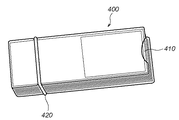
図18は連続静止画がプリントされた短冊状シートを本実施形態のケースに束ねて収容した状態を示す図である。図18に示されるように、コの字状のケース部材400と、これに収容される短冊状シート群410と、ケース部材400と短冊状シート群410を束ねて、その状態を維持するための保持部材としての輪ゴム420を具備する。また、図19は、図18に示すように収容された短冊を連続的に捲ることにより、捲り動画を観察する様子を示した図である。図19では、左綴じ(右利き用)の状態が示されている。
【0101】
図20は、本実施形態によるケースの組み立ての様子を説明する図である。ケース部材400は、柔軟で、透明もしくは半透明の材料からなり、略長方形の第1パネル401と、コの字状とした際に第1パネル401に対向する略長方形の第2パネル402、及び第1パネル401と第2パネル402を接続する第3パネル403を含んで構成される。図21に示すように、好ましくは第1〜第3パネルは一体のシートから形成され、点線で示した折り目線410により、第1〜第3パネルが形成される。図21に示すシートは、図20の(a)に示すように、折り目線410において折り曲げ可能に構成され、これにより第1〜第3パネル401〜403はコの字状に形成される。
【0102】
次に、図20(b)に示されるように、第1パネル401と第2パネル402との間に、積み重ねられた短冊状シート群410(本例では45枚の短冊状シート)が挿入される。したがって、第3パネルの長さ(コの字状に形成した場合の高さ方向の長さ)は、短冊状シート45枚を重ねた厚みと同等とする。
【0103】
第1パネル401と第2パネル402の各長辺部上の、第3パネル403との接続部位側にはノッチ404が設けられている。これらのノッチ404は、第3パネル403との接続部位より等距離に設けられている。第1と第3パネル、及び第2と第3パネルのそれぞれがなす角度をほぼ直角としてコの字状にケース400を形成し、その中に短冊群410を入れ、ノッチ404に輪ゴム420をかけることにより、短冊を束ねた状態を維持する(図20(c)、(d))。
【0104】
第1パネル401は連続静止画と接する上面パネルであり、第2パネル402は背表紙となるパネルである。第1パネル401と第2パネル402は、収容する短冊状シートよりも一回り大きいサイズを有する。これにより、短冊状シート群410に対する保護機能が提供される。
【0105】
ところで、上面パネルとしての第1パネル401を収容する短冊状シートより大きくすると、連続的に捲ろうとした場合に、最初の方の短冊状シートが数枚同時に捲れてしまうという問題が生じる。そこで、本実施形態では、図22等に示されるように、収容している短冊が露出するように切り欠き405を設け、連続的に捲る際に、先頭の短冊状シートが指に接触するようにしてある。これにより、先頭の短冊状シートから確実に一枚ずつ捲れるようになる。切り欠き405の幅は、人間の指(親指)が短冊に触れて、自然に捲ることのできるような大きさとする。なお、切り欠き形状は、円弧形状に限定されるものではない。
【0106】
また、短冊状シートにおいて、連続静止画の周りに縁が設けてある場合は、この縁部分のみが露出する程度の切り込み深さとするようにしてもよい(図22(b))。このようにすれば、連続静止画そのものは露出しないので、画像を確実に保護できる。
【0107】
また、第2パネル402は背表紙となるパネルであるが、第1パネル401と同様に、短冊状シートよりも一回り大きいサイズを有するのが好ましい。このような第2パネル402を設けたことにより、短冊状シートを確実に保護するとともに、連続的な捲り操作をした場合に、最後のページまで確実に1枚ずつ捲ることを容易にする効果がある。すなわち、第2パネル402が存在しない場合、或は短冊状シートよりも小さい場合、最後の方で複数枚のページが同時に捲れてしまい、正しく捲り動画を観察できないという問題が生じるが、本実施形態によれば、第2パネルを設けたことで、最終ページまで容易かつ確実に1枚ずつ捲ることができるようになるのである。
【0108】
さらに、上述したノッチ404も、図22(c)に示すように、収容された短冊がわずかに露出する程度の深さを有することが望ましい。このようにノッチを形成することにより、ノッチ404によって輪ゴム420の位置がずれないようにするとともに、短冊状シートと輪ゴム420を接触させることにより、より良好かつ効果的に、短冊状シート群410の収容状態を維持できる。また、本実施形態の、輪ゴムによる保持機構によれば、極めて簡易な構成で、効果的に短冊群410を保持する保持手段を提供できる。更に、クリップのようなもので直接的に短冊状シート群を挟む場合には、クリップによって短冊状シートを傷める可能性がある。しかし、本実施形態によれば、ケースによって保護された状態で輪ゴム420をかけるので、短冊状シートを傷める心配はない。
【0109】
なお、各短冊状シートの、ケース部材400に収容した際のノッチ404に相当する位置に、ノッチを設けるようにしてもよい。これは例えば図24のような用紙を提供することで実現できる。この用紙は、ミシン目602上に、ノッチを形成する穴601が設けられる。このような構成の場合、輪ゴム420が、ケース部材のノッチ404と各短冊状シートのノッチ601にフィットし、収容した短冊状シートをより確実に保持することができる。
【0110】
なお、複数の輪ゴムを用いて束ねられるように、複数組のノッチを設けてもよいことは明らかである。
【0111】
また、上記実施形態では、第1パネル〜第3パネルを用いてコの字状のケースを提供するが、短冊状シートの保護、捲り動画の観察を可能とするべく短冊状シートを束ねた状態で維持するという観点からすれば、第3パネル403を省略してもよい。ただし、上記実施形態で説明したように、第1〜第3パネルを用いて構成することにより、ケース部材400を1枚のシートから形成できること、また第3パネルが背表紙として短冊状シートの束を揃える機能が提供される等のメリットがある。
【0112】
[他の実施形態]
なお、本発明は、複数の機器(例えばホストコンピュータ,インターフェース機器,リーダ,プリンタなど)から構成されるシステムに適用しても、一つの機器からなる装置(例えば、複写機,ファクシミリ装置など)に適用してもよい。
【0113】
また、本発明の目的は、前述した実施形態の機能を実現するソフトウェアのプログラムコードを記録した記憶媒体を、システムあるいは装置に供給し、そのシステムあるいは装置のコンピュータ(またはCPUやMPU)が記憶媒体に格納されたプログラムコードを読出し実行することによっても、達成されることは言うまでもない。
【0114】
この場合、記憶媒体から読出されたプログラムコード自体が前述した実施形態の機能を実現することになり、そのプログラムコードを記憶した記憶媒体は本発明を構成することになる。
【0115】
プログラムコードを供給するための記憶媒体としては、例えば、フレキシブルディスク,ハードディスク,光ディスク,光磁気ディスク,CD−ROM,CD−R,磁気テープ,不揮発性のメモリカード,ROMなどを用いることができる。
【0116】
また、コンピュータが読出したプログラムコードを実行することにより、前述した実施形態の機能が実現されるだけでなく、そのプログラムコードの指示に基づき、コンピュータ上で稼働しているOS(オペレーティングシステム)などが実際の処理の一部または全部を行い、その処理によって前述した実施形態の機能が実現される場合も含まれることは言うまでもない。
【0117】
さらに、記憶媒体から読出されたプログラムコードが、コンピュータに挿入された機能拡張ボードやコンピュータに接続された機能拡張ユニットに備わるメモリに書込まれた後、そのプログラムコードの指示に基づき、その機能拡張ボードや機能拡張ユニットに備わるCPUなどが実際の処理の一部または全部を行い、その処理によって前述した実施形態の機能が実現される場合も含まれることは言うまでもない。
【0118】
【発明の効果】
以上説明したように本発明によれば、動画中の所望の範囲から所定枚数の連続静止画を得ることによりユーザの要求にきめ細かく対応できるとともに、指定された所望範囲の広狭に関わらず所定枚数の連続静止画を取得できる。このため、ユーザは所定枚数の連続静止画を取得できるかどうかを気にせずに、所望の範囲を指定することができる。
【図面の簡単な説明】
【図1】本実施形態による画像形成システムの構成を示すブロック図である。
【図2】図1に示した画像形成システムの情報処理装置100を、ソフトウエア構成の観点から説明する図である。
【図3】用紙選択画面が選択された状態において実行される処理を説明するフローチャートである。
【図4】動画選択画面が選択された状態において実行される処理を説明するフローチャートである。
【図5】範囲設定画面が選択された状態において実行される処理を説明するフローチャートである。
【図6】印刷・保存画面が選択された状態において実行される処理を説明するフローチャートである。
【図7】用紙選択画面の表示例を示す図である。
【図8】動画選択画面の表示例を示す図である。
【図9A】範囲設定画面の表示例を示す図である。
【図9B】範囲設定画面におけるプレビュー操作用インターフェースを示す図である。
【図10A】印刷・保存画面の表示例を示す図である。
【図10B】印刷出力例を示す図である。
【図11】ステップS149、S162における静止画変換処理を更に詳細に説明するフローチャートである。
【図12】用紙搬送誤差による連続静止画像の印刷への影響を説明する図である。
【図13】用紙搬送誤差による連続静止画像の印刷への影響を説明する図である。
【図14】本実施形態による右綴じ用の印刷レイアウトを説明する図である。
【図15】左綴じ用に印刷レイアウトした場合の問題を説明する図である。
【図16】本実施形態による左綴じ用の印刷レイアウトを説明する図である。
【図17】本実施形態による印刷レイアウトの処理を説明する図である。
【図18】連続静止画がプリントされた短冊状シートを本実施形態のケースに収容した状態を示す図である。
【図19】本実施形態のケースに収容された短冊状シートにより、捲り動画を観察する様子を示す図である。
【図20】本実施形態によるケースの組み立て手順を説明する図である。
【図21】本実施形態のケースの部材構成を示す図である。
【図22】本実施形態のケースにおける切り欠きの構成を示す図である。
【図23】本実施形態において連続静止画を印刷するための用紙を示す図である。
【図24】本実施形態において連続静止画を印刷するための用紙の別の形態を示す図である。
【図25】従来技術における連続静止画のプリント出力を示す図である。
【図26】図25に示すプリント出力より得られた短冊状シートを束ねて、捲り動画を観察する様子を示す図である。[0001]
BACKGROUND OF THE INVENTION
The present invention relates to an image processing method and apparatus for printing out a plurality of images obtained from moving image data, and a printing apparatus.
[0002]
[Prior art]
An apparatus that prints a continuous movement of a subject as a plurality of images has been proposed. As an example of this type of apparatus, for example, one described in JP-A-10-327376 can be cited.
[0003]
According to Japanese Patent Application Laid-Open No. 10-327376, a predetermined number of captured images are obtained and stored from the video camera output from the instruction to start shooting until the preset shooting time elapses, as shown in FIG. The printout is described as follows. In this print output, a blank portion is provided on the side of each captured image, and this blank portion can be bundled as shown in FIG. The user can observe the captured image as a moving image by continuously rolling the bundled prints as shown in FIG. Hereinafter, in this specification, such a moving image is referred to as a “rolling moving image”. A continuous still image that provides a moving video is referred to as a continuous still image.
[0004]
In addition, the position of the margin part of the print output in FIG. 25 can designate either the left side or the right side of the captured image, so that it can cope with the case where the user is right-handed or left-handed. That is, if the margin is specified to be provided on the left side of the captured image, a right-handed (left-binding) printout can be obtained, and if the margin is specified to be provided on the right side of the captured image, the left-handed A printout (for right binding) can be obtained.
[0005]
[Problems to be solved by the invention]
Generally, in this type of apparatus, captured images are taken out at predetermined time intervals and stored for outputting continuous still images for the entire range from the start to the end of shooting. According to Japanese Patent Application Laid-Open No. 10-327376, when a desired shooting time of 8 seconds, 10 seconds, and 12 seconds is specified, shooting is performed at the specified shooting time, and a predetermined interval is set between the shooting times. The captured image is stored. For example, if 8 seconds are specified, the captured images are stored every 1/6 second to store 48 captured images, and if 10 seconds are specified, 1/1 to store 48 captured images. A captured image is stored every 5 seconds.
[0006]
However, for example, when a shooting time of 10 seconds is specified but the portion of interest to the user is the portion from 2 seconds to 9 seconds, the captured images included in the first and last 1 second are useless. Print output. Japanese Patent Application Laid-Open No. 2001-223876 only describes that “a moving image may be taken and individual frames may be cut out from the moving image at regular time intervals”.
[0007]
As described above, in the related art, there is a problem that it is not possible to obtain a print output that closely corresponds to the user's interest because the image is only cut out for the entire series of captured moving images.
[0008]
In Japanese Patent Application Laid-Open No. 10-327376 and Japanese Patent Application Laid-Open No. 2001-223876, there is no concept of setting a specified desired range in a moving image as a still image cutout range. However, no consideration is given to the case where the predetermined number of continuous still images cannot be generated.
[0009]
The present invention has been made in view of the above-described problems. By obtaining a predetermined number of continuous still images from a desired range in a moving image, it is possible to meticulously respond to a user's request and to narrow the specified desired range. It is an object to make it possible to acquire a predetermined number of continuous still images regardless of the number.
[0010]
[Means for Solving the Problems]
In order to achieve the above object, an image processing apparatus according to the present invention comprises the following arrangement. That is,
An image processing apparatus for printing a plurality of continuous still images that can be observed as a moving video based on video data,
The video data Medium range A designation means for designating,
The video data Specified by specifying means Than range Predetermined number Determining means for determining whether or not the frame can be extracted;
When it is determined by the determination means that extraction is possible, Designated Than range The predetermined number To extract the frame Predetermined First generation means for generating a number of continuous still images;
When it is determined by the determination means that extraction is not possible, Designated Than range Extraction Extract the possible number of frames to generate continuous still images, and make up for the shortage by repeatedly using the same frame, The predetermined Second generation means for generating a number of continuous still images.
[0011]
Further, an image processing method according to the present invention for achieving the above object is as follows:
An image processing method for printing a plurality of continuous still images that can be observed as a moving video based on video data,
The video data Medium range A specified process for specifying
The video data Specified in the specified process Than range Predetermined number A determination step of determining whether or not the frame can be extracted;
When it is determined in the determination step that extraction is possible, Designated Than range The predetermined number To extract the frame Predetermined number A first generation step of generating a continuous still image of
When it is determined in the determination step that extraction is not possible, Designated Than range Extraction Extract the possible number of frames to generate continuous still images, and make up for the shortage by repeatedly using the same frame, The predetermined number A second generation step of generating a continuous still image.
[0012]
Furthermore, the printing apparatus of the present invention that achieves the above-described object is as follows.
A printing device that prints a plurality of continuous still images that can be observed as a moving video based on video data,
The video data During ~ A specifying means for specifying the range of
The video data Specified by specifying means Than range Predetermined number Determining means for determining whether or not the frame can be extracted;
When it is determined by the determination means that extraction is possible, Designated Than range Predetermined Extract a number of frames Predetermined First generation means for generating a number of continuous still images;
When it is determined by the determination means that extraction is not possible, Designated Than range Extraction Extract the possible number of frames to generate continuous still images, and make up for the shortage by repeatedly using the same frame, The predetermined Second generation means for generating a number of continuous still images;
Generated by the first or second generation means; Predetermined Printing means for printing a number of continuous still images.
[0013]
DETAILED DESCRIPTION OF THE INVENTION
Hereinafter, preferred embodiments of the present invention will be described with reference to the accompanying drawings.
[0014]
[System configuration]
FIG. 1 is a block diagram showing the configuration of the image forming system according to the present embodiment. The image forming system according to this embodiment includes an
[0015]
The
[0016]
In this embodiment, a mouse is used as the pointing device (PD), but various devices such as a trackball and a touch panel can be used. In the above configuration, the
[0017]
The
[0018]
The
[0019]
The
[0020]
On the other hand, the
[0021]
In the above configuration, when the
[0022]
FIG. 2 is a diagram for explaining the
[0023]
A keyboard and a mouse (KB / PD) 151 are connected to the
[0024]
Input made using the keyboard and mouse is processed by the keyboard /
[0025]
As the
[0026]
The
[0027]
When the
[0028]
If the
[0029]
[About print processing applications]
Next, the print processing application according to the present embodiment that can operate as the
[0030]
When the print processing application of the present embodiment is activated, a dedicated application window is displayed. As the application window, a paper selection screen (see FIG. 7), a moving image selection screen (see FIG. 8), a range setting screen (see FIG. 9A), and a print / save screen (see FIG. 10A) are prepared. When the print application is activated, a paper selection window is displayed as the initial screen, but the present invention is not limited to this. Each screen is provided with tabs (301a to 301d) for screen selection, and the screen can be shifted to a desired screen among the screens of FIGS. 7 to 10A by clicking the desired tab. it can.
[0031]
The outline printing procedure by this print processing application is as follows.
-Set the printer and paper to be used on the paper selection screen,
-Select the desired video file on the video selection screen,
-In the range setting screen, set the desired range in the video file selected on the video selection screen and check whether the range set by the preview of the hitting video is appropriate,
On the print / save screen, a predetermined number of continuous still images are generated from the desired range set on the range setting screen, and are output by the set printer.
[0032]
Hereinafter, details of the operation will be described for each screen.
[0033]
First, with reference to FIG. 3 and FIG. 7, a paper selection process executed by displaying a paper selection screen will be described. FIG. 3 is a flowchart for explaining processing executed when the paper selection screen shown in FIG. 7 is selected.
[0034]
In step S101, the name of the printer to be selected is input in the
[0035]
In step S102, the cartridge is selected using the
[0036]
In step S104, it is determined whether a tab (any one of 301b to 301d) for shifting to another screen is selected. If not selected, the process returns to step S101. If a tab for shifting to another screen is selected, the process proceeds to step S105, and the contents set at that time in
[0037]
Next, a moving image selection process executed when the
[0038]
First, in step S121, a process for opening the selected file is performed by the user's file opening operation. Here, a pop-up window (not shown) for file selection is displayed in response to the click of the “Open”
[0039]
Next, in step S122, it is determined whether the file specified in step S121 is created and saved by the print processing application. In this application, information for printing a continuous still image can be saved in step S169 in the “print and save” process described later with reference to FIG. If it is determined in step S122 that such an information file has been selected, the moving image reproduction process described below is not performed, and the process proceeds to step S126. Note that the determination in step S122 can be performed with reference to, for example, a file extension.
[0040]
As will be described later, the information file stores an image file name, a still image clipping range, and the like. Therefore, in the present embodiment, a configuration is adopted in which the screen is automatically switched to the print / save screen so that printing can be executed immediately when the information file is opened. That is, when the information file is opened on the moving image selection screen, the step of reproducing the moving image is skipped, and the process jumps to the print / save screen (this jump process is not shown in the flowchart). It should be noted that such a configuration may not be adopted, and even when an information file is selected, it may be possible to reproduce a moving image in the same manner as when a normal moving image file is selected.
[0041]
If the file selected in step S121 is a moving image file that can be processed by the printing application, the process proceeds to step S123, and the image of the first frame of the moving image file is displayed in the moving
[0042]
The
[0043]
When the reproduction of the moving image is instructed by the operation of the
[0044]
When any of the
[0045]
Next, the range setting process executed when the
[0046]
As shown in FIG. 9A, a moving
[0047]
First, the moving image reproduction process in steps S141 to S143 is the same as that in steps S123 to S125 described above. That is, the image of the first frame of the moving image file selected and confirmed on the moving image selection screen is displayed in the moving image reproduction area 323 (step S141), and the
[0048]
If the
[0049]
In the above description, the desired range in the moving image is determined by designating the start point and the ending point at a desired time point during reproduction of the moving image file. However, the present invention is not limited to this. For example, by moving the seek
[0050]
Further, the above-described method for specifying a still image cutout range while reproducing a moving image and the method for specifying a still image cutout range using a seek bar may be combined. For example, the seek
[0051]
In this embodiment, the start point and end point of the still image cutout range are registered according to the reproduction time. However, the present invention is not limited to this, and a frame number or the like may be used.
[0052]
The print processing application of this embodiment cuts out a predetermined number of still images (45 in this embodiment) at equal intervals from the still image cutout range set as described above, and prints them out. To do. The print output of the continuous still image obtained in this way is separated into strips as described above, and is intended to be observed as a moving video by rolling continuously. Therefore, for this purpose, it is desirable to be able to preview a continuous still image so that a moving image can be observed in a pseudo manner. In the following steps S148 to S150, such a preview function is provided.
[0053]
When the
[0054]
Note that the frame extraction in step S149 can be performed at substantially equal intervals by using the following expression. That is,
m = 1 + INT ((n-1) x (M-1) / (N-1) + 0.5)
However, INT (x) is a function that obtains the value after truncating the decimal point of x,
M: Number of frames in the selection range
N: Number of extracted frames (N> 1, fixed to 45 in this embodiment)
n: Frame sequence number (1 to N)
m: Extraction frame number (1 to M)
(M, N, n, and m are all integers)
And In the above equation, when M = (N−1) × y + 1 (y is an integer of 1 or more), the intervals between the frames are all equal.
In step S150, the continuous still images generated in step S149 are sequentially displayed in the imaging order so that, for example, 45 images are displayed in 2 seconds. At this time, the switching interval from one still image to the next still image is made constant (for example, 2/45 seconds if 45 continuous still images are displayed in 2 seconds).
[0055]
If the
[0056]
In this state, when the
[0057]
In the preview display of continuous still images in step S150, a
[0058]
Further, manual operation may be enabled as indicated by
[0059]
Next, processing when the
[0060]
First, in step S161, it is determined whether or not the still image conversion process in step S149 has been performed for the currently set clipping target range. If the processing in step S149 has been completed, a continuous still image has been obtained for the still image cutout range, and step S162 is skipped. If a continuous still image has not been acquired from the set extraction target range, the process proceeds to step S162, and a predetermined number of continuous still images are extracted from the still image extraction range set on the previous range setting screen. This process is the same as step S149 in FIG.
[0061]
Subsequently, in step S163, the
[0062]
If the
[0063]
<Layout>
・ Right binding: Print with a left-handed layout.
・ Left binding: Print with a right-handed layout.
(Default is “Left Binding”)
<Background>
-None: Nothing is printed around continuous still images.
-Black gradation: Prints a black gradation that changes from the continuous still image toward the margin around the continuous still image.
・ Specified color gradation: Prints the specified color gradation that changes from the continuous still image toward the margin around the continuous still image.
(Default is “Black gradient”)
<Title>
-None: Does not print the title name.
-Print title: Prints the input character string as a title (can be set to print only on the first page or on all pages).
(Default is “None”)
<Shooting date>
-None: Does not print the shooting date and time.
-Print date: Prints the date of shooting (can be set to print only on the first page or all pages)
(The default is "None").
[0064]
After the print setting, the process returns to step S163 to display the print layout with the updated print setting. In this way, the print setting change is immediately reflected in the print layout display.
[0065]
When the
[0066]
When the
[0067]
The 45 continuous still images obtained as described above are printed on a sheet having a perforation as shown in FIG. 23 as shown in FIG. 10A, so that these can be separated into strip-like sheets along the perforations. In this case, they can be bundled as shown in FIG. Then, a continuous moving image can be observed by continuously speaking as shown in FIG.
[0068]
As described above, according to the print processing application of the present embodiment, it is possible to print out a continuous still image that can be observed as a moving moving image in a desired range of moving image data. It is possible to easily provide a roaring video that the user desires.
[0069]
In particular, in the preview function using the
[0070]
In addition, if the still image switching interval can be set in the preview, it is possible to perform a preview according to the desired turning speed. Further, in the preview, if a configuration for controlling switching of continuous still images in synchronization with the movement of the
[0071]
[Continuous still image replenishment processing when the number of frames is insufficient]
As described above, in the present embodiment, a desired range in a moving image can be specified by specifying a moving image cutout start point and a moving image cutout end point on the range setting screen. For this reason, there is a possibility that a cutout range of less than 45 frames may be specified depending on how the range is specified. In such a case, 45 continuous still images cannot be generated in steps S149 and S162. The print processing application of this embodiment can appropriately obtain 45 continuous still images even in such a case.
[0072]
FIG. 11 is a flowchart for explaining the still image conversion process in steps S149 and S162 in more detail.
[0073]
First, in step S201, the still image cutout range (start point and end point) set in steps S144 to S147 described above is read as conversion range information. In step S202, the number of frames included in the still image cutout range is obtained. In step S203, the still image conversion number is read. As described above, since the number of images is fixed to 45 in this embodiment, the number of still image conversions is 45.
[0074]
In step S204, the number of frames included in the still image clipping range obtained in step S202 is compared with the number of still image conversions (45) read in step S203. If the number of frames in the cutout range is equal to or greater than the number of still image conversions, 45 continuous still images can be cut out, so the process proceeds to step S207, and a predetermined number of frames are equally spaced at the same method as in step S149 described above. Extract and convert still image.
[0075]
On the other hand, when the number of frames in the cutout range is smaller than the number of still image conversions, it is necessary to generate 45 continuous still images by compensating for the shortage. Therefore, the process proceeds from step S204 to step S205. In step S205, all frames included in the designated still image cutout range are converted into still images. In step S206, the shortage is compensated by repeatedly using frames within the still image cutout range. In the present embodiment, the first and / or last frame in time series is repeatedly used (that is, the continuous still images corresponding to the first and / or last frame in time series are repeatedly used). Create a specified number of continuous still images. This is because, when observing a moving video, the user feels uncomfortable when the same image is repeated in the middle. However, even if several identical still images are repeated at the beginning or at the end, the user does not feel much discomfort.
[0076]
Further, the method of replenishing continuous still images may be changed according to the number of repetitions (insufficient number). That is, the frame position used for repetition may be changed according to the shortage. For example, if the shortage number is less than or equal to a predetermined threshold, the continuous still image of the first and / or last frame is repeatedly used, and if the shortage number is greater than the predetermined threshold, repeated use of the continuous still image is scattered throughout all frames. Let
[0077]
For example, the ratio of the shortage to the predetermined number is
・ Repeat the last frame up to 10% (up to 5 if the number is 45)
・ In the case of 10% to 20% (6 to 9), repeat the last frame until the first 10% (5), and make up for the remaining shortage by repeating the first frame.
・ If it exceeds 20% (10 or more frames), it is possible to arrange repeated frames throughout. Alternatively, if a shortage exceeding 20% occurs, a range specification error may be generated.
[0078]
Alternatively, the user may designate which frame (frame at which position) is repeated. For example, the user may be able to set whether to repeat “last frame” or “first frame”.
[0079]
In the above method, the repetition of the last frame is used preferentially. In the observation of the moving image, it becomes difficult to move one by one on the last page, and a plurality of This is because there is a case where you drown at once. Therefore, the process of replenishing a continuous still image by repeating the last frame is a very effective means that can suppress the influence on the print output for observing the moving video and can simplify the process itself. .
[0080]
In addition, when a continuous still image of the same frame is repeated, predetermined processing may be performed on the image. For example, when repeating the same image several times toward the end, a continuous still image for replenishment may be generated by gradually reducing the luminance of the image and adding a fade-out effect. Similarly, when several frames are repeated on the head side, the replenishment continuous still image may be generated by adjusting the brightness of the print data so as to have an effect such as fade-in.
[0081]
[Details of print processing]
The continuous still image according to the present embodiment is printed on a sheet having a perforation for cutting into a strip shape, cut into a strip shape along the perforation, and a blank portion provided on the side of the still image. Are bound together as a binding margin, and a moving animation can be observed. Therefore, unless a still image is printed at a predetermined position in the strip formed by the perforation with good reproducibility, the entire image moves when a moving moving image is observed, which is unnatural. In general, the printing position is kept relatively accurately on one sheet of paper. However, when a continuous still image is printed across a plurality of sheets as in the present embodiment, there is a problem of deviation in the entire printing position between different sheets.
[0082]
Generally, the printing position accuracy is low due to the influence of a conveyance error in the paper conveyance direction. On the other hand, with respect to the printing position in the direction orthogonal to the transport direction, a relatively good accuracy can be obtained by a paper guide or the like. Accordingly, as shown in FIG. 12, when printing is performed with a layout in which the arrangement of continuous still images and margins is orthogonal to the conveyance direction, a strip-like sheet obtained from one sheet and a strip obtained from the next sheet are printed. With the sheet-like sheet, the printing position of the continuous still image is more easily shifted in the vertical direction than in the horizontal direction. For this reason, in the rolling animation of this embodiment in which 15 strip-like sheets are obtained from one sheet, the 15th and 16th strip-like sheets and the 30th and 31st strip-like sheets are used. The continuous still image moves up and down between the sheets.
[0083]
According to the experiments by the present inventors, when observing a moving video, the sense of discomfort is greater when the continuous still image is shifted in the vertical direction than when the continuous still image is shifted in the horizontal direction. Therefore, in the present embodiment, in the printing process in step S167, a still image is laid out and printed out so as to minimize the vertical shift. Hereinafter, this point will be described.
[0084]
FIG. 13 is a diagram for explaining a layout in print output of continuous still images according to the present embodiment. As shown in FIG. 13, in the print output of the present embodiment, each strip is provided with a continuous still image and a margin portion that can be used for binding, but the arrangement of the continuous still image and the margin portion is always in the transport direction. Make sure they are in the same direction. As described above, when recording on a plurality of sheets, the print position system in the direction orthogonal to the transport direction is more accurate than the print position accuracy in the transport direction. Therefore, when the print output obtained by the layout as shown in FIG. 13 is separated along the perforations, and the obtained strip-like sheets are bundled and the moving image is observed, the horizontal movement of the still image is slightly Although there is a possibility of increasing the size, the vertical positions of the still images coincide with each other with relatively high accuracy. As described above, when moving and observing still images continuously, moving in the vertical direction is more likely to feel uncomfortable than moving in the horizontal direction. It is possible to provide a strip-like sheet that allows observation of a moving image.
[0085]
Note that it is easy to understand that the layout shown in FIG. 12 is used when the paper is conveyed in landscape orientation. Therefore, in a situation where the paper transport direction can be specified, it is preferable that an appropriate print layout is automatically selected according to the transport direction. That is, the designated transport direction and paper size are detected, the print layout is determined so that the continuous still image and the blank portion are aligned in the transport direction, and the print process is performed.
[0086]
As described above, in the present embodiment, it is possible to lay out and print continuous still images so that the printing position accuracy in the vertical direction is higher than that in the horizontal direction when observing a moving video.
[0087]
Furthermore, in the print output of the present embodiment, further improvements are made in order to improve the print image quality of continuous still images. When printing is performed by repeating recording scanning in the direction orthogonal to the transport direction while transporting the paper as in the ink jet recording apparatus, a transport error is likely to occur particularly in the rear end of the paper in the transport direction, and the image quality is deteriorated. Tend to. This is because the sheet is softly pressed at the rear end portion of the sheet, the conveyance error becomes remarkable, the sheet easily floats, and the distance between the recording head and the sheet changes.
[0088]
As described above, when the continuous still image and the blank portion are arranged along the sheet conveyance direction, one of the continuous still image and the blank portion is positioned at the trailing edge of the sheet. FIG. 14 shows the layout for right binding and the paper transport direction during printing. In the case of the layout as shown in FIG. 14, since a blank portion is formed on the rear end side of the sheet in the sheet conveyance direction, there is no adverse effect on the continuous still image due to the above reason. However, when the layout for left binding is designated, as shown in FIG. 15, when the layout is moved and the recording position of the continuous still image is moved so that the margin portion is on the left of the continuous still image, the trailing edge of the paper A continuous still image is arranged on the part side. Therefore, there is a possibility that the print image quality of the 11th to 15th continuous still images deteriorates.
[0089]
In order to solve this problem, in the present embodiment, the margin is always arranged on the rear end side of the sheet in both the right binding layout and the left binding layout. In the present embodiment, this is realized by further rotating the print layout for left binding as shown in FIG. 15 by 180 degrees to obtain a print layout as shown in FIG.
[0090]
FIG. 17 is a flowchart for explaining this print processing. When the printing process in step S168 is started, this process is started.
[0091]
First, in step S301, print setting layout information, that is, information indicating whether the set layout is for left binding or right binding is acquired. If the acquired layout information represents a layout for right binding, the process proceeds from step S302 to step S304, and a continuous still image is laid out so that a print output as shown in FIG. 14 is performed. Then, the process proceeds to step S305 to execute continuous still image print output.
[0092]
On the other hand, if the layout information acquired in step S301 represents a left-binding layout, the process advances from step S302 to step S303. In step S303, the continuous still image printing position is moved to the right side of the strip to a state as shown in FIG. 15, and this is rotated 180 degrees to obtain the print layout shown in FIG. In step S305, continuous still image printing is executed. As a result, as shown in FIGS. 14 and 16, a margin is always located at the trailing edge of the sheet, and deterioration of the image quality of continuous still images can be prevented.
[0093]
In the above embodiment, a layout rotated by 180 degrees is used in the case of the left binding layout, but the present invention is not limited to such a process. What is necessary is to perform a print layout so that a continuous still image and a blank portion are aligned in the transport direction, and the blank portion is on the rear end side of the sheet in the transport direction.
[0094]
In the print layout display in step S163, a continuous still image is always displayed for the normal position. Therefore, even when left binding is set in this embodiment, the layout display is performed so that the continuous still image is in the normal position, that is, as shown in FIG. 10A.
[0095]
As described above, according to the present embodiment, by devising the print layout according to the characteristics of the printing apparatus, specifically, the continuous still image and the blank portion are arranged along the transport direction, and By adopting a print layout that has a margin on the trailing edge of the paper in the transport direction, it has become possible to provide a high-quality curling movie.
[0096]
The print application of this embodiment has been described above. In the above embodiment, the print processing application is described as operating on an information processing apparatus such as a personal computer. However, the present invention is not limited to this, and all or some of the functions of the application are printers. It may be realized in a driver, a digital camera, a digital video camera, or a printer.
[0097]
In the above embodiment, an inkjet printer is assumed as the printer, but an electrophotographic printer such as a laser printer or a thermal printer may be used.
[0098]
In the above embodiment, the number of continuous still images is fixed at 45, but may be arbitrarily set by the user. Also, for example, when the layout changes depending on the orientation of the paper and the number of strip-like sheets that can be acquired from one paper changes (for example, when the paper is conveyed sideways and the layout shown in FIG. 12 is used, the
[0099]
[About strip case]
Next, a case will be described in which a plurality of strip-like sheets including a continuous still image printed out as described above are bundled and accommodated so that a moving animation can be observed.
[0100]
FIG. 18 is a diagram showing a state in which strip-like sheets on which continuous still images are printed are bundled and accommodated in the case of this embodiment. 18, the
[0101]
FIG. 20 is a view for explaining how the case is assembled according to the present embodiment. The
[0102]
Next, as illustrated in FIG. 20B, the stacked strip-shaped sheet group 410 (45 strip-shaped sheets in this example) is inserted between the
[0103]
A
[0104]
The
[0105]
By the way, if it is larger than the strip-shaped sheet that accommodates the
[0106]
Further, in the strip-shaped sheet, when an edge is provided around the continuous still image, the cut depth may be such that only the edge portion is exposed (FIG. 22B). In this way, since the continuous still image itself is not exposed, the image can be reliably protected.
[0107]
In addition, the
[0108]
Furthermore, it is desirable that the above-described
[0109]
In addition, you may make it provide a notch in the position corresponded to the
[0110]
Obviously, a plurality of sets of notches may be provided so as to be bundled using a plurality of rubber bands.
[0111]
Moreover, in the said embodiment, although a U-shaped case is provided using the 1st panel-3rd panel, the state which bundled the strip-shaped sheet | seat so that protection of a strip-shaped sheet | seat and the observation of a turn animation could be performed From the viewpoint of maintaining the above, the
[0112]
[Other Embodiments]
Note that the present invention can be applied to a system (for example, a copier, a facsimile machine, etc.) consisting of a single device even when applied to a system composed of a plurality of devices (for example, a host computer, interface device, reader, printer, etc.). You may apply.
[0113]
Another object of the present invention is to supply a storage medium recording a program code of software for realizing the functions of the above-described embodiments to a system or apparatus, and the computer (or CPU or MPU) of the system or apparatus stores the storage medium. Needless to say, this can also be achieved by reading and executing the program code stored in the.
[0114]
In this case, the program code itself read from the storage medium realizes the functions of the above-described embodiments, and the storage medium storing the program code constitutes the present invention.
[0115]
As a storage medium for supplying the program code, for example, Flexible disk , Hard disk, optical disk, magneto-optical disk, CD-ROM, CD-R, magnetic tape, nonvolatile memory card, ROM, and the like can be used.
[0116]
Further, by executing the program code read by the computer, not only the functions of the above-described embodiments are realized, but also an OS (operating system) operating on the computer based on the instruction of the program code. It goes without saying that a case where the function of the above-described embodiment is realized by performing part or all of the actual processing and the processing is included.
[0117]
Further, after the program code read from the storage medium is written into a memory provided in a function expansion board inserted into the computer or a function expansion unit connected to the computer, the function expansion is performed based on the instruction of the program code. It goes without saying that the CPU or the like provided in the board or the function expansion unit performs part or all of the actual processing, and the functions of the above-described embodiments are realized by the processing.
[0118]
【The invention's effect】
As described above, according to the present invention, by obtaining a predetermined number of continuous still images from a desired range in a moving image, it is possible to respond precisely to the user's request, and a predetermined number of images regardless of the width of the specified desired range. Continuous still images can be acquired. For this reason, the user can designate a desired range without worrying about whether or not a predetermined number of continuous still images can be acquired.
[Brief description of the drawings]
FIG. 1 is a block diagram illustrating a configuration of an image forming system according to an embodiment.
FIG. 2 is a diagram illustrating an
FIG. 3 is a flowchart illustrating processing executed in a state where a paper selection screen is selected.
FIG. 4 is a flowchart illustrating processing executed when a moving image selection screen is selected.
FIG. 5 is a flowchart illustrating processing executed in a state where a range setting screen is selected.
FIG. 6 is a flowchart illustrating processing executed in a state where a print / save screen is selected.
FIG. 7 is a diagram illustrating a display example of a paper selection screen.
FIG. 8 is a diagram illustrating a display example of a moving image selection screen.
FIG. 9A is a diagram showing a display example of a range setting screen.
FIG. 9B is a diagram showing a preview operation interface on a range setting screen.
FIG. 10A is a diagram showing a display example of a print / save screen.
FIG. 10B is a diagram illustrating an example of print output.
FIG. 11 is a flowchart illustrating still image conversion processing in steps S149 and S162 in more detail.
FIG. 12 is a diagram for explaining an influence on printing of a continuous still image due to a paper transport error.
FIG. 13 is a diagram for explaining an influence on printing of a still image by a paper conveyance error.
FIG. 14 is a diagram illustrating a print layout for right binding according to the present embodiment.
FIG. 15 is a diagram illustrating a problem when a print layout is performed for left binding.
FIG. 16 is a diagram illustrating a print layout for left binding according to the present embodiment.
FIG. 17 is a diagram illustrating a print layout process according to the present embodiment.
FIG. 18 is a diagram illustrating a state in which a strip-like sheet on which a continuous still image is printed is accommodated in the case of the present embodiment.
FIG. 19 is a diagram showing a state in which a turning movie is observed by a strip-shaped sheet accommodated in the case of the present embodiment.
FIG. 20 is a view for explaining the procedure for assembling the case according to the present embodiment;
FIG. 21 is a diagram showing a member configuration of a case of the present embodiment.
FIG. 22 is a diagram showing a configuration of notches in the case of the present embodiment.
FIG. 23 is a diagram illustrating a sheet for printing a continuous still image in the present embodiment.
FIG. 24 is a diagram illustrating another form of paper for printing a continuous still image in the present embodiment.
FIG. 25 is a diagram showing print output of continuous still images in the prior art.
FIG. 26 is a diagram showing a state in which a striped sheet obtained from the print output shown in FIG.
Claims (18)
前記動画データ中の範囲を指定する指定手段と、
前記動画データの前記指定手段で指定された範囲より予め定められた数のフレームを抽出可能か判定する判定手段と、
前記判定手段で抽出可能と判定された場合に、前記指定された範囲より前記予め定められた数のフレームを抽出して該予め定められた数の連続静止画を生成する第1生成手段と、
前記判定手段で抽出可能ではないと判定された場合に、前記指定された範囲より抽出可能な数のフレームを抽出して連続静止画を生成し、不足分を同一のフレームの繰り返し利用により補って、前記予め定められた数の連続静止画を生成する第2生成手段と
を備えることを特徴とする画像処理装置。An image processing apparatus for printing a plurality of continuous still images that can be observed as a moving video based on video data,
A designation means for designating a range in the video data;
Determining means for determining whether a predetermined number of frames can be extracted from a range specified by the specifying means of the moving image data;
First generation means for extracting the predetermined number of frames from the specified range and generating the predetermined number of continuous still images when the determination means determines that extraction is possible;
When it is determined by the determination means that extraction is not possible, a number of frames that can be extracted from the specified range are extracted to generate a continuous still image, and the shortage is compensated by repeated use of the same frame. An image processing apparatus comprising: a second generation unit configured to generate the predetermined number of continuous still images.
前記動画データ中の範囲を指定する指定工程と、
前記動画データの前記指定工程で指定された範囲より予め定められた数のフレームを抽出可能か判定する判定工程と、
前記判定工程で抽出可能と判定された場合に、前記指定された範囲より前記予め定められた数のフレームを抽出して該予め定められた数の連続静止画を生成する第1生成工程と、
前記判定工程で抽出可能ではないと判定された場合に、前記指定された範囲より抽出可能な数のフレームを抽出して連続静止画を生成し、不足分を同一のフレームの繰り返し利用により補って、前記予め定められた数の連続静止画を生成する第2生成工程と
を備えることを特徴とする画像処理方法。An image processing method for printing a plurality of continuous still images that can be observed as a moving video based on video data,
A designation step for designating a range in the video data;
A determination step of determining whether a predetermined number of frames can be extracted from the range specified in the specifying step of the moving image data;
A first generation step of extracting the predetermined number of frames from the specified range and generating the predetermined number of continuous still images when it is determined that the extraction is possible in the determination step;
If it is determined in the determination step that extraction is not possible, a number of frames that can be extracted from the specified range are extracted to generate a continuous still image, and the shortage is compensated by repeated use of the same frame. A second generation step of generating the predetermined number of continuous still images. An image processing method comprising:
前記動画データ中の範囲を指定する指定手段と、
前記動画データの前記指定手段で指定された範囲より予め定められた数のフレームを抽出可能か判定する判定手段と、
前記判定手段で抽出可能と判定された場合に、前記指定された範囲より予め定められた数のフレームを抽出して該予め定められた数の連続静止画を生成する第1生成手段と、
前記判定手段で抽出可能ではないと判定された場合に、前記指定された範囲より抽出可能な数のフレームを抽出して連続静止画を生成し、不足分を同一のフレームの繰り返し利用により補って、前記予め定められた数の連続静止画を生成する第2生成手段と、
前記第1もしくは第2生成手段で生成された前記予め定められた数の連続静止画を印刷する印刷手段と
を備えることを特徴とする印刷装置。A printing device that prints a plurality of continuous still images that can be observed as a moving video based on video data,
Designating means for designating a range in said motion picture data,
Determining means for determining whether a predetermined number of frames can be extracted from a range specified by the specifying means of the moving image data;
If it is judged to be extracted by the judging unit, a first generation means for generating a continuous still image of the defined number of the previously extracted the predetermined number of frames than the specified range,
When it is determined by the determination means that extraction is not possible, a continuous still image is generated by extracting a number of frames that can be extracted from the specified range, and the shortage is compensated by repeated use of the same frame. Second generation means for generating the predetermined number of continuous still images;
And a printing unit that prints the predetermined number of continuous still images generated by the first or second generation unit.
Priority Applications (4)
| Application Number | Priority Date | Filing Date | Title |
|---|---|---|---|
| JP2001335187A JP3768861B2 (en) | 2001-10-31 | 2001-10-31 | Image processing method and apparatus, and printing apparatus |
| US10/282,786 US7345783B2 (en) | 2001-10-31 | 2002-10-29 | Image processing method and apparatus for generating sequential still images by extracting still images from moving image data, and printing apparatus |
| US11/408,526 US7426058B2 (en) | 2001-10-31 | 2006-04-21 | Image processing method and apparatus for generating sequential still images by extracting still images from moving image data, and printing apparatus |
| US12/125,356 US20080219598A1 (en) | 2001-10-31 | 2008-05-22 | Image processing method and apparatus for generating sequential still images by extracting still images from moving image data, and printing apparatus |
Applications Claiming Priority (1)
| Application Number | Priority Date | Filing Date | Title |
|---|---|---|---|
| JP2001335187A JP3768861B2 (en) | 2001-10-31 | 2001-10-31 | Image processing method and apparatus, and printing apparatus |
Publications (3)
| Publication Number | Publication Date |
|---|---|
| JP2003143537A JP2003143537A (en) | 2003-05-16 |
| JP2003143537A5 JP2003143537A5 (en) | 2004-10-28 |
| JP3768861B2 true JP3768861B2 (en) | 2006-04-19 |
Family
ID=19150201
Family Applications (1)
| Application Number | Title | Priority Date | Filing Date |
|---|---|---|---|
| JP2001335187A Expired - Fee Related JP3768861B2 (en) | 2001-10-31 | 2001-10-31 | Image processing method and apparatus, and printing apparatus |
Country Status (1)
| Country | Link |
|---|---|
| JP (1) | JP3768861B2 (en) |
Families Citing this family (3)
| Publication number | Priority date | Publication date | Assignee | Title |
|---|---|---|---|---|
| JP3809411B2 (en) | 2002-09-27 | 2006-08-16 | キヤノン株式会社 | Image processing method and apparatus, and printing apparatus |
| JP4579707B2 (en) * | 2004-04-16 | 2010-11-10 | キヤノン株式会社 | Printing apparatus, printing method, computer-readable storage medium storing program, and program |
| JP4701734B2 (en) * | 2005-02-04 | 2011-06-15 | セイコーエプソン株式会社 | Print based on video |
-
2001
- 2001-10-31 JP JP2001335187A patent/JP3768861B2/en not_active Expired - Fee Related
Also Published As
| Publication number | Publication date |
|---|---|
| JP2003143537A (en) | 2003-05-16 |
Similar Documents
| Publication | Publication Date | Title |
|---|---|---|
| US7426058B2 (en) | Image processing method and apparatus for generating sequential still images by extracting still images from moving image data, and printing apparatus | |
| US10289350B2 (en) | Information processing device, printing condition setting method, and computer product | |
| JP3809411B2 (en) | Image processing method and apparatus, and printing apparatus | |
| US20050243371A1 (en) | Document processing apparatus and method | |
| US7929182B2 (en) | Image processing apparatus, image processing method, program, and recording medium | |
| JP2004318581A (en) | Information processor and method of displaying print preview | |
| US10114527B2 (en) | Display control device, display device, printing apparatus, display control method and non-transitory computer readable medium storing program for displaying process of duplex print processing | |
| JP2005071187A (en) | Device and method for converting document | |
| JP2006293598A (en) | Document processing system | |
| JP4332461B2 (en) | Image processing apparatus and method | |
| JP3768861B2 (en) | Image processing method and apparatus, and printing apparatus | |
| JP2004064231A (en) | Image processing method and apparatus | |
| JP3768860B2 (en) | Image processing method and apparatus, and printing apparatus | |
| JP2004104679A (en) | Method and device for image processing and printer | |
| JP2003136874A (en) | Case for turned-over moving images | |
| JP2003140869A (en) | Image processing method and device and printing device | |
| KR200305950Y1 (en) | Case for page-flipping moving images, and page-flipping moving image set | |
| US20090122337A1 (en) | Host apparatus for an image forming apparatus and an image printing method thereof | |
| JP2003143514A (en) | Case for moving image to be turned over and set of moving images to be turned over | |
| JP2004235889A (en) | Image processor | |
| JP2003136801A (en) | Image processing method, image processor and printer | |
| JP2005167633A (en) | Image processor and method therefor | |
| JP2004173211A (en) | Image processor | |
| JP4447549B2 (en) | Information processing apparatus, program, and recording medium | |
| JP2007156631A (en) | Printer driver |
Legal Events
| Date | Code | Title | Description |
|---|---|---|---|
| A977 | Report on retrieval |
Free format text: JAPANESE INTERMEDIATE CODE: A971007 Effective date: 20051018 |
|
| A131 | Notification of reasons for refusal |
Free format text: JAPANESE INTERMEDIATE CODE: A131 Effective date: 20051024 |
|
| A521 | Written amendment |
Free format text: JAPANESE INTERMEDIATE CODE: A523 Effective date: 20051222 |
|
| TRDD | Decision of grant or rejection written | ||
| A01 | Written decision to grant a patent or to grant a registration (utility model) |
Free format text: JAPANESE INTERMEDIATE CODE: A01 Effective date: 20060123 |
|
| A61 | First payment of annual fees (during grant procedure) |
Free format text: JAPANESE INTERMEDIATE CODE: A61 Effective date: 20060202 |
|
| R150 | Certificate of patent or registration of utility model |
Free format text: JAPANESE INTERMEDIATE CODE: R150 |
|
| FPAY | Renewal fee payment (event date is renewal date of database) |
Free format text: PAYMENT UNTIL: 20100210 Year of fee payment: 4 |
|
| FPAY | Renewal fee payment (event date is renewal date of database) |
Free format text: PAYMENT UNTIL: 20100210 Year of fee payment: 4 |
|
| FPAY | Renewal fee payment (event date is renewal date of database) |
Free format text: PAYMENT UNTIL: 20110210 Year of fee payment: 5 |
|
| FPAY | Renewal fee payment (event date is renewal date of database) |
Free format text: PAYMENT UNTIL: 20120210 Year of fee payment: 6 |
|
| FPAY | Renewal fee payment (event date is renewal date of database) |
Free format text: PAYMENT UNTIL: 20130210 Year of fee payment: 7 |
|
| FPAY | Renewal fee payment (event date is renewal date of database) |
Free format text: PAYMENT UNTIL: 20140210 Year of fee payment: 8 |
|
| LAPS | Cancellation because of no payment of annual fees |