JP3765451B2 - Waterproof power window device - Google Patents
Waterproof power window device Download PDFInfo
- Publication number
- JP3765451B2 JP3765451B2 JP01155798A JP1155798A JP3765451B2 JP 3765451 B2 JP3765451 B2 JP 3765451B2 JP 01155798 A JP01155798 A JP 01155798A JP 1155798 A JP1155798 A JP 1155798A JP 3765451 B2 JP3765451 B2 JP 3765451B2
- Authority
- JP
- Japan
- Prior art keywords
- window
- switch
- relay
- contact
- terminal
- Prior art date
- Legal status (The legal status is an assumption and is not a legal conclusion. Google has not performed a legal analysis and makes no representation as to the accuracy of the status listed.)
- Expired - Fee Related
Links
Images


Landscapes
- Power-Operated Mechanisms For Wings (AREA)
- Window Of Vehicle (AREA)
Description
【0001】
【発明の属する技術分野】
本発明は、防水型パワーウインド装置に係わり、特に、何等かの原因によって自動車が水中に落ちたような場合、ウインド下降スイッチの操作によりドアウインドを確実に開くことができるようにした防水型パワーウインド装置に関する。
【0002】
【従来の技術】
一般に、自動車に用いられるパワーウインド装置は、自動車が水中に落ちたような場合、ウインド上昇スイッチやウインド下降スイッチに浸水し、それらスイッチの各接点間が浸水によって電気的絶縁状態の維持が困難になり、ウインド上昇スイッチ及びウインド下降スイッチの各接点が開いているにも係わらず、それらの接点が比較的小さな抵抗値を介して電気的に導通した状態になり、以後、ウインド下降スイッチを操作しても、ウインドの下降操作、即ち、ウインドの開放操作を行なうことができなくなる。
【0003】
図3は、かかる既知のパワーウインド装置の主要な部分の回路構成の一例を示す回路図である。
【0004】
図3に示されるように、パワーウインド装置は、ウインド上昇スイッチ31と、ウインド上昇リレー32及びその接点32Cと、ウインド下降スイッチ33と、ウインド下降リレー34及びその接点34Cと、自動ウインド上昇スイッチ35と、自動ウインド下降スイッチ36と、ウインド開閉用モーター37と、制御用集積回路(以下、制御ICという)38と、車載電源39とからなっている。
【0005】
そして、車載電源39と接地点間に、ウインド上昇スイッチ31とウインド上昇リレー32が直列接続され、ウインド下降スイッチ33とウインド下降リレー34が直列接続される。ウインド上昇スイッチ31とウインド上昇リレー32の接続点Aは制御IC38の端子▲1▼、▲4▼に接続され、ウインド下降スイッチ33とウインド下降リレー34の接続点Bは制御IC38の端子▲2▼、▲5▼に接続される。自動ウインド上昇スイッチ35は、一端が接続点Aに、他端が制御IC38の端子▲3▼にそれぞれ接続され、自動ウインド下降スイッチ36は、一端が接続点Bに、他端が制御IC38の端子▲3▼にそれぞれ接続される。ウインド上昇リレー32の接点32Cは、可動接点がウインド開閉用モーター37の一端に、一方の固定接点が車載電源39に、他方の固定接点が接地点にそれぞれ接続される。ウインド下降リレー34の接点34Cは、可動接点がウインド開閉用モーター37の他端に、一方の固定接点が車載電源39に、他方の固定接点が接地点にそれぞれ接続される。制御IC38の端子▲6▼は車載電源39に接続される。
【0006】
前記構成によるパワーウインド装置は、概略、次のように動作する。
【0007】
ドライバー等がウインド上昇スイッチ31を操作すると、その接点が閉じ、ウインド上昇リレー32が車載電源39によって駆動される。このとき、ウインド上昇リレー32の接点32Cが切替わり、ウインド開閉用モーター37が一方方向に回転し、それによりウインドが上昇方向(ウインド閉方向)に移動する。そして、ウインド上昇スイッチ31の操作を停止すれば、その接点が開き、ウインド上昇リレー32の駆動が停止され、ウインド開閉用モーター37の回転も停止してウインドが上昇も停止する。一方、ウインド下降スイッチ33を操作すると、その接点が閉じ、ウインド下降リレー34が車載電源39によって駆動される。このとき、ウインド下降リレー34の接点34Cが切替わり、ウインド開閉用モーター37が他方方向に回転し、それによりウインドが下降方向(ウインド開方向)に移動する。そして、ウインド下降スイッチ33の操作を停止すれば、その接点が開き、ウインド下降リレー34の駆動が停止され、ウインド開閉用モーター37の回転も停止してウインドの下降も停止する。
【0008】
また、ドライバー等が自動ウインド上昇スイッチ35を操作すると、その接点が閉じるとともに、ウインド上昇スイッチ31が同時操作され、その接点も閉じるようになる。このウインド上昇スイッチ31の接点の閉鎖により、ウインド上昇リレー32が車載電源39によって駆動され、前述のウインド上昇スイッチ31を操作した場合と同様に、ウインド開閉用モーター37が一方方向に回転し、それによりウインドが上昇方向(ウインド閉方向)に移動する。また、ウインド上昇スイッチ31の接点及び自動ウインド上昇スイッチ35の接点がともに閉じることにより、制御IC38の端子▲1▼及び▲3▼にそれぞれ接続点Aの電圧が供給され、その電圧の供給に応答して、制御IC38の端子▲4▼に車載電源39の電圧がラッチされて出力され、この電圧がウインド上昇リレー32に供給される。このため、自動ウインド上昇スイッチ35の操作を停止し、その接点が開かれ、同時に、ウインド上昇スイッチ31の操作が停止され、その接点が開かれたとしても、端子▲4▼の出力電圧はラッチされているので、ウインド上昇リレー32は駆動され続け、ウインド開閉用モーター37が続いて一方方向に回転し、それによりウインドが上昇方向に移動し続ける。そして、このウインドの上昇方向への移動は、ウインドが全閉状態になるまで続行される。
【0009】
同様にして、自動ウインド下降スイッチ36を操作すると、その接点が閉じるとともに、ウインド下降スイッチ33も同時操作され、その接点も閉じる。この場合においても、前述のウインド下降スイッチ33を操作した場合と同様に、ウインド開閉用モーター37が他方方向に回転し、それによりウインドが下降方向(ウインド開方向)に移動する。また、ウインド下降スイッチ33の接点及び自動ウインド下降スイッチ36の接点がともに閉じることにより、制御IC38の端子〔2〕及び〔3〕(図では丸付数字で示しているが、ここではカッコ付数字で示す。)にそれぞれ接続点Bの電圧が供給され、その電圧の供給に応答して、制御IC38の端子〔5〕(図では丸付数字で示しているが、ここではカッコ付数字で示す。)に車載電源39の電圧がラッチされて出力され、この電圧がウインド下降リレー34に供給される。このため、自動ウインド下降スイッチ36の操作を停止し、その接点が開かれ、同時に、ウインド下降スイッチ33の操作が停止され、その接点が開かれたとしても、端子〔5〕(図では丸付数字で示しているが、ここではカッコ付数字で示す。)の出力電圧はラッチされているので、ウインド下降リレー34は駆動され続け、ウインド開閉用モーター37が続いて他方方向に回転し、それによりウインドが下降方向に移動し続ける。そして、このウインドの下降方向への移動はウインドが全開状態になるまで続行される。
【0010】
ところで、前記既知のパワーウインド装置は、何等かの原因で自動車が水中に落ち、ウインド上昇スイッチ31やウインド下降スイッチ33に浸水した場合、それらスイッチ31、33の接点間に水による比較的抵抗値の小さな漏洩抵抗31R、33Rが接続された形になり、ウインド上昇スイッチ31及びウインド下降スイッチ33の各接点が開いているにも係わらず、ウインド上昇リレー32及びウインド下降リレー34にこれらの漏洩抵抗31R、33Rを通して車載電源39の出力電圧が加わり、ウインド上昇リレー32及びウインド下降リレー34が同時駆動されるか、ウインド上昇リレー32及びウインド下降リレー34が同時半駆動されるようになり、その結果、それらの接点32C、34Cが同時に切替えられた状態になるか、または、それらの接点32C、34Cがいずれの固定接点にも切替えられない状態になる。その結果、モーター37は回転駆動されない。このとき、自動車のドライバー等がウインドを開くために、ウインド下降スイッチ33を操作しても、ウインド開閉用モーター37が回転駆動されず、ウインドが開かれない状態になる。このように、前記既知のパワーウインド装置は、自動車が水中に落ち、浸水状態になったとき、もはや正常なウインド操作を行うことができなくなるという問題を有している。
【0011】
このような問題点を解決するために、本出願人は、一端が車載電源または接地点に選択的に接続される1回路2接点の第1スイッチと第1リレーとからなる第1直列回路、一端が車載電源または接地点に選択的に接続される第2スイッチと第2リレーからなる第2直列回路、制御用集積回路を備え、第1直列回路の他端が第2スイッチと第2リレーの接続点に接続され、第2直列回路の他端が第1スイッチと第1リレーの接続点に接続され、第1スイッチの接点切替により第1リレーを付勢してモーターを一方方向に回転駆動させ、ウインドを上昇させるとともに、第2スイッチの接点切替により第2リレーを付勢してモーターを他方方向に回転駆動させ、ウインドを下降させる防水型パワーウインド装置を既提案しており、特願平9−335728号として出願されている。
【0012】
ここで、図4は、前記提案による防水型パワーウインド装置の構成を示す回路構成図である。
【0013】
図4に示されるように、防水型パワーウインド装置は、1回路2接点のウインド上昇スイッチ41と、ウインド上昇リレー42及びその接点42Cと、1回路2接点のウインド下降スイッチ43と、ウインド下降リレー44及びその接点44Cと、自動ウインド上昇スイッチ45と、自動ウインド下降スイッチ46と、第1逆流防止ダイオード47と、第2逆流防止ダイオード48と、第3逆流防止ダイオード49と、第4逆流防止ダイオード50と、ウインド開閉用モーター51と、制御用集積回路(以下、制御ICとういう)52と、車載電源53とからなっている。
【0014】
また、ウインド上昇スイッチ41の可動接点と第3逆流防止ダイオード49と第1逆流防止ダイオード47とウインド上昇リレー42は直列接続され、第1直列回路を構成する。ウインド下降スイッチ43の可動接点と第4逆流防止ダイオード50と第2逆流防止ダイオード48とウインド下降リレー44は直列接続され、第2直列回路を構成する。ウインド上昇スイッチ41は、常閉接点が接地接続され、常開接点が車載電源53に接続される。ウインド上昇リレー42は、他端がウインド下降スイッチ43の可動接点と第4逆流防止ダイオード50の接続点B1に接続される。ウインド下降スイッチ43は、常閉接点が接地接続され、常開接点が車載電源53に接続される。ウインド下降リレー44は、他端がウインド上昇スイッチ41の可動接点と第3逆流防止ダイオード49の接続点A1に接続される。第3逆流防止ダイオード49と第1逆流防止ダイオード47の接続点A2は制御IC52の端子〔1〕及び端子〔4〕(図では丸付数字で示しているが、ここではカッコ付数字で示す。)に接続され、第4逆流防止ダイオード50と第2逆流防止ダイオード48の接続点B2は制御IC52の端子〔2〕及び端子〔5〕(図では丸付数字で示しているが、ここではカッコ付数字で示す。)に接続される。
【0015】
前記構成による防水型パワーウインド装置は、概略、次のように動作する。
【0016】
ドライバー等がウインド上昇スイッチ41を操作すると、可動接点が図示の常閉接点側から常開接点側に切替わり、車載電源53の電圧は、切替わったウインド上昇スイッチ41、第3逆流防止ダイオード49、第1逆流防止ダイオード47、ウインド上昇リレー42、可動接点が図示の常閉接点側に切替わっているウインド下降スイッチ43を介して接地点に達し、ウインド上昇リレー42が駆動される。このとき、ウインド上昇リレー42の接点42Cは可動接点が図示の接続状態から逆の接続状態に切替わり、ウインド開閉モーター51に車載電源53の電圧が供給され、ウインド開閉モーター51が一方方向に回転し、ウインドを上昇させ、ウインドを閉じる。そして、ウインド上昇スイッチ41の操作を停止すれば、可動接点が図示の常閉接点側に切替わり、車載電源53の電圧がウインド上昇スイッチ41で阻止され、ウインド上昇リレー42の駆動が停止するので、ウインド開閉モーター51の回転が停止し、ウインドの上昇が停止し、ウインドはその位置に保持される。
【0017】
一方、ドライバー等がウインド下降スイッチ43を操作すると、可動接点が図示の常閉接点側から常開接点側に切替わり、車載電源53の電圧は、切替わったウインド下降スイッチ43、第4逆流防止ダイオード50、第2逆流防止ダイオード48、ウインド下降リレー44、可動接点が図示の常閉接点側に切替わっているウインド上昇スイッチ41を介して接地点に達し、ウインド下降リレー44が駆動される。このとき、ウインド下降リレー44の接点44Cは可動接点が図示の接続状態から逆の接続状態に切替わり、ウインド開閉モーター51に車載電源53の電圧が供給され、ウインド開閉モーター51が他方方向に回転し、ウインドが下降し、ウインドを開く。そして、ウインド下降スイッチ43の操作を停止すれば、可動接点が図示の常閉接点側に切替わり、車載電源53の電圧がウインド下降スイッチ43で阻止され、ウインド下降リレー44の駆動が停止するので、ウインド開閉モーター51の回転が停止し、ウインドの下降が停止し、ウインドはその位置に保持される。
【0018】
また、ドライバー等が自動ウインド上昇スイッチ45を操作すると、操作に連動してウインド上昇スイッチ41も同時操作され、自動ウインド上昇スイッチ45の可動接点が閉じ、ウインド上昇スイッチ41の可動接点が図示の常閉接点側から常開接点側に切替わる。ウインド上昇スイッチ41の可動接点の切替えにより、車載電源53の電圧がウインド上昇スイッチ41、第3逆流防止ダイオード49、第1逆流防止ダイオード47を介してウインド上昇リレー42に印加され、前記ウインド上昇スイッチ41を単独操作した場合と同様に、ウインド上昇リレー42が駆動され、ウインド開閉モーター51が一方方向に回転して、ウインドを上昇させ、ウインドを閉じる。このとき、自動ウインド上昇スイッチ45の可動接点が閉じると、制御IC52の端子▲3▼に車載電源53の電圧が印加され、制御用IC52は、端子▲6▼に供給される車載電源43の電圧を端子▲1▼に出力し、ウインド上昇リレー42に供給する。ここで、自動ウインド上昇スイッチ45の操作を停止し、連動するウインド上昇スイッチ41の操作も停止すると、ウインド上昇スイッチ41の可動接点が常開接点側から常閉接点側に切替わり、ウインド上昇スイッチ41を介するウインド上昇リレー42への車載電源53の電圧の供給は停止されるが、制御IC52の端子▲1▼から出力される車載電源53の電圧の供給はラッチされ、ウインド上昇リレー42への車載電源53の電圧の供給が持続されるので、ウインド上昇リレー42は駆動され続ける。このため、ウインド開閉モーター41は一方方向に回転を続け、ウインドを上昇させ続ける。ウインドの上昇は、ウインドが移動範囲の最上部にまで到達し、ウインド全閉状態になるまで続けられる。
【0019】
同様に、ドライバー等が自動ウインド下降スイッチ46を操作すると、操作に連動してウインド下降スイッチ43も同時操作され、自動ウインド下降スイッチ46の可動接点が閉じ、ウインド下降スイッチ43の可動接点が図示の常閉接点側から常開接点側に切替わる。ウインド下降スイッチ43の可動接点が常開接点側に切替わると、車載電源53の電圧がウインド下降スイッチ43、第4逆流防止ダイオード50、第2逆流防止ダイオード48を介してウインド下降リレー44に印加され、ウインド下降スイッチ43を単独操作した場合と同様に、ウインド下降リレー44が駆動され、ウインド開閉モーター51が他方方向に回転し、ウインドを下降させ、ウインドを開く。このとき、自動ウインド下降スイッチ46の可動接点が閉じたことで、制御IC52の端子〔3〕(図では丸付数字で示しているが、ここではカッコ付数字で示す。)に車載電源53の電圧が印加され、制御IC52は、端子〔6〕(図では丸付数字で示しているが、ここではカッコ付数字で示す。)に供給される車載電源53の電圧を端子〔2〕(図では丸付数字で示しているが、ここではカッコ付数字で示す。)に出力し、ウインド下降リレー44に供給する。ここで、自動ウインド下降スイッチ46の操作を停止し、連動するウインド下降スイッチ43の操作も停止すると、ウインド下降スイッチ43の可動接点が常開接点側から常閉接点側に切替わり、ウインド下降スイッチ43を介するウインド下降リレー44への車載電源53の電圧の供給は停止されるが、制御IC52の端子〔2〕(図では丸付数字で示しているが、ここではカッコ付数字で示す。)から出力される車載電源53の電圧の供給はラッチされ、ウインド下降リレー44への車載電源53の電圧の供給が持続され、ウインド下降リレー44は駆動され続ける。このため、ウインド開閉モーター51は他方方向に回転を続け、ウインドを下降し続ける。このウインドの下降は、ウインドが移動範囲の最下部にまで到達し、ウインド全開状態になるまで続けられる。
【0020】
さらに、ウインドが完全に閉じた状態または完全に閉じた状態に近い状態のとき、自動車が何等かの原因で水中に落ちたとすると、ドアの内部に取り付けられているこの防水型パワーウインド装置も浸水状態になる。この防水型パワーウインド装置は、大部分の構成部品は防水処理されているが、ウインド上昇スイッチ41、ウインド下降スイッチ43、自動ウインド上昇スイッチ45、自動ウインド下降スイッチ46は、いずれも完全な防水処理を行なうことができないため、浸水時に僅かながら水が浸入するようになる。そして、ウインド上昇スイッチ41やウインド下降スイッチ43内に水が浸入すると、前述のように、それらの可動接点と常開接点との間に比較的抵抗値の小さい水による漏洩抵抗が接続されたものと等価になるが、ウインド上昇スイッチ41及びウインド下降スイッチ43は、常閉接点が接地接続されているので、ウインド上昇スイッチ41及びウインド下降スイッチ43に加えられた車載電源53の電圧は、可動接点と常開接点との間にある漏洩抵抗と常閉接点側に切替わっている可動接点を通して接地点に流れ、ウインド上昇リレー42及びウインド下降リレー44に印加されない。このため、ウインド上昇リレー42の接点42C及びウインド下降リレー44の接点44Cは図示の接続状態になっており、ウインド開閉モーター51は回転駆動されない。
【0021】
このような状態のとき、ドライバー等がウインド下降スイッチ43を操作すると、ウインド下降スイッチ43の接点が常閉接点側から常開接点側に切替わり、常開接点と可動接点との間に接続されていた水による漏洩抵抗が接点の切替えによって短絡状態になり、同時に、常閉接点側と可動接点との間が短絡状態から開放状態になり、今度は常閉接点側と可動接点との間に水による漏洩抵抗が接続されるようになる。このため、車載電源53の電圧は、短絡状態のウインド下降スイッチ43、第4逆流防止ダイオード50、第2逆流防止ダイオード48を介してウインド下降リレー44に供給され、ウインド下降リレー44が駆動される。そして、ウインド下降リレー44の駆動により、接点44Cが図示の接続状態から逆の接続状態に切替わり、ウインド開閉モーター51に車載電源53の電圧が印加され、ウインド開閉モーター51が他方方向に回転駆動される。これによりウインドが下降し、ウインドが開くので、ドライバー等は開いたウインドから脱出することが可能になる。
【0022】
【発明が解決しようとする課題】
前記提案による防水型パワーウインド装置は、一応、自動車が水中に落ち、防水型パワーウインド装置に浸水したような場合に、ウインド下降スイッチ43の操作を行なうことによってウインドを開くことができるものであるが、前述したように、ウインド下降スイッチ43を操作してその接点が常開接点側に切替わり、常開接点と可動接点が短絡状態になって車載電源53の電圧がウインド下降リレーに供給される際、同時に、常閉接点側と可動接点との間は開放状態になっているが、比較的抵抗値の小さい水による漏洩抵抗が接続されるようになるため、この漏洩抵抗を通して接地点に漏洩電流が分流し、ウインド下降リレー44に流れる駆動電流はその分だけ小さくなって、ウインド下降リレー44の接点44Cが切替えられず、その結果ウインド開閉用モータ51が回転駆動されないで、ウインドが開かれない状態になる虞れがある。
【0023】
このように、前記提案による防水型パワーウインド装置は、自動車が水中に落ち、防水型パワーウインド装置が浸水状態になったとき、ウインド下降スイッチを操作しても確実にウインドを開くことができず、防水型パワーウインド装置の動作の信頼性を確保することが難しいという問題を有している。
【0024】
本発明は、これらの問題点を悉く解決するもので、その目的は、防水型パワーウインド装置への浸水を迅速に検知し、その検知によって直ちに浸水への対応が可能な状態に移行させる信頼性の高い防水型パワーウインド装置を提供することにある。
【0025】
【課題を解決するための手段】
前記目的を達成するために、本発明の防水型パワーウインド装置は、第1直列回路における第1リレーの駆動端を制御用集積回路の第1端子に、第2直列回路における第2リレーの駆動端を制御用集積回路の第2端子にそれぞれ接続し、制御用集積回路の電源端子と接地端子との間に、制御端子に水没検知素子を接続した半導体検知素子を接続し、パワーウインド装置の浸水による水没検知素子の水没検知時に半導体検知素子をオンにし、制御用集積回路の第1端子及び第2端子から電源電圧を出力する手段を具備する。
【0026】
前記手段によれば、自動車が水中に落ち、防水型パワーウインド装置に浸水したときに、防水型パワーウインド装置の全体に浸水が及ぶ前に水没検知素子がいち早く水没検知を行ない、直ちに半導体検知素子をオンにし、制御用集積回路の第1端子及び第2端子から電源電圧を出力させ、ウインドを上昇させる(閉じる)第1リレー及びウインドを下降させる(開く)第2リレーにそれぞれ電源電圧を供給するようにしているので、この時点に、ウインドを上昇させる第1スイッチまたはウインドを下降させる第2スイッチを操作することにより、ウインドを上昇またはウインドを下降させることができ、特に、第2スイッチの操作によりウインドを下降させ、開いたウインドから確実に脱出することが可能になる。
また、前記目的を達成するために、本発明の防水型パワーウインド装置は、第1スイッチ及び第2スイッチ及び水没検知素子がそれぞれ接続されて、水没検知素子が水の浸入を検知したときの第2スイッチの操作でウインドの開動作を可能なように制御する制御部を具備する。
該手段によれば、防水型パワーウインド装置への浸水を迅速に検知し、その検知によって直ちに浸水への対応が可能な状態に移行させることが可能となる。
【0027】
【発明の実施の形態】
本発明の実施の形態において、防水型パワーウインド装置は、一端が車載電源または接地点に選択的に接続される1回路2接点の第1スイッチと第1リレーとからなる第1直列回路、一端が車載電源または接地点に選択的に接続される1回路2接点の第2スイッチと第2リレーからなる第2直列回路、制御用集積回路を備え、第1リレーの第1スイッチが接続されていない他端が第2スイッチと第2リレーの接続点に接続され第1リレーの第1スイッチが接続されている一端が制御用集積回路の第1端子に接続され、第2リレーの第2スイッチが接続されていない他端が第1スイッチと第1リレーの接続点に接続され第2リレーの第2スイッチが接続されている一端が制御用集積回路の第2端子に接続され、第1スイッチの接点切替により第1リレーを付勢してモーターを一方方向に回転駆動させ、ウインドを上昇させるとともに、第2スイッチの接点切替により第2リレーを付勢してモーターを他方方向に回転駆動させ、ウインドを下降させるものであって、制御用集積回路は、電源端子と接地端子との間に、制御端子に水没検知素子を接続した半導体検知素子が接続され、水没検知素子の水没検知時に半導体検知素子がオンになり、第1端子及び第2端子から電源電圧を出力させるものである。
【0028】
本発明の実施の形態の具体例において、防水型パワーウインド装置は、半導体検知素子がトランジスタからなるものである。
【0029】
本発明の実施の形態の他の具体例において、防水型パワーウインド装置は、水没検知素子が微小間隔をおいて露出状態で配置した一対の導電金属パッドからなるものである。
【0030】
これらの本発明の実施の形態によれば、制御用集積回路の電源端子と接地端子との間に、制御端子に水没検知素子を接続した半導体検知素子を接続し、水没検知素子の水没検知時に半導体検知素子をオンにし、第1端子及び第2端子から電源電圧を出力させて、ウインドを上昇させる(閉じる)第1リレー及びウインドを下降させる(開く)第2リレーに供給するようにしているので、自動車が水中に落ち、防水型パワーウインド装置内に浸水したとき、露出した状態の水没検知素子がいち早く水没検知を行ない、直ちに半導体検知素子をオンにし、制御用集積回路の第1端子及び第2端子から電源電圧を出力し、第1リレー及び第2リレーにそれぞれ電源電圧を供給するようにしているので、この時点に、ウインドを上昇させる第1スイッチまたはウインドを下降させる第2スイッチを操作すれば、ウインドを上昇またはウインドを下降させることができるもので、特に、第2スイッチの操作によってウインドを下降させるようにすれば、水没中の自動車における開いたウインドから確実に車外に脱出することが可能になる。
また、本発明の実施の形態において、防水型パワーウインド装置は、車載電源と、ウインドを開閉するモータと、手動によりウインドの閉動作を指示してウインドを閉方向に駆動されるようモータに車載電源を接続する第1スイッチと、手動によりウインドの開動作を指示してウインドを開方向に駆動されるようモータに車載電源を接続する第2スイッチと、水没検知素子と、第1スイッチ及び第2スイッチ及び水没検知素子がそれぞれ接続されて、水没検知素子が水の浸入を検知したときに第2スイッチの操作でウインドの開動作を可能なように制御する制御部とを有するものである。
この本発明の実施の形態によれば、防水型パワーウインド装置への浸水を迅速に検知し、その検知によって直ちに浸水への対応が可能な状態に移行させることが可能となる。
【0031】
【実施例】
以下、本発明の実施例を図面を参照して説明する。
【0032】
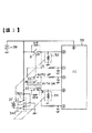
図1は、本発明による防水型パワーウインド装置の第1実施例の要部構成を示す回路図である。
【0033】
図1に示されるように、第1実施例の防水型パワーウインド装置は、1回路2接点のスイッチからなるウインド上昇スイッチ(第1スイッチ)1と、ウインド上昇リレー2及びその接点2Cと、1回路2接点のスイッチからなるウインド下降スイッチ(第2スイッチ)3と、ウインド下降リレー4及びその接点4Cと、自動ウインド上昇スイッチ5と、自動ウインド下降スイッチ6と、第1逆流防止ダイオード7と、第2逆流防止ダイオード8と、第3逆流防止ダイオード9と、第4逆流防止ダイオード10と、ウインド開閉用モーター11と、制御用集積回路(以下、制御ICという)12と、車載電源(バッテリー)13と、一対の導電金属パッド(水没検知素子)14と、トランジスタ(半導体検知素子)15と、抵抗16、17と、ダイオード18とを備えている。
【0034】
そして、ウインド上昇スイッチ1の可動接点と第3逆流防止ダイオード9と第1逆流防止ダイオード7とウインド上昇リレー2は直列接続されて第1直列回路を構成する。ウインド下降スイッチ3の可動接点と第4逆流防止ダイオード10と第2逆流防止ダイオード8とウインド下降リレー4は直列接続されて第2直列回路を構成する。ウインド上昇スイッチ1は、一方の固定接点(常閉接点)が接地接続され、他方の固定接点(常開接点)が車載電源13に接続され、可動接点が第3逆流防止ダイオード9のアノードに接続される。ウインド上昇リレー2は、一端が第1逆流防止ダイオード7のカソードに接続され、他端がウインド下降スイッチ3の可動接点と第4逆流防止ダイオード10のアノードとの接続点B1に接続される。第1逆流防止ダイオード7のアノード及び第3逆流防止ダイオード9のカソードとの接続点A2は、制御IC12の端子〔1〕(図では丸付数字で示しているが、ここではカッコ付数字で示す。)及び端子(第1端子)〔4〕(図では丸付数字で示しているが、ここではカッコ付数字で示す。)に接続される。ウインド下降スイッチ3は、一方の固定接点(常閉接点)が接地接続され、他方の固定接点(常開接点)が車載電源13に接続される。ウインド下降リレー4は、一端が第2逆流防止ダイオード8のカソードに接続され、他端がウインド上昇スイッチ1の可動接点と第3逆流防止ダイオード9のアノードとの接続点A1に接続される。第2逆流防止ダイオード8のアノードと第4逆流防止ダイオード10のカソードとの接続点B2は制御IC12の端子〔2〕(図では丸付数字で示しているが、ここではカッコ付数字で示す。)及び端子(第2端子)〔5〕(図では丸付数字で示しているが、ここではカッコ付数字で示す。)に接続される。
【0035】
また、自動ウインド上昇スイッチ5は、可動接点が車載電源13に接続され、固定接点が制御IC12の端子▲3▼に接続される。自動ウインド下降スイッチ6は、可動接点が車載電源13に接続され、固定接点が制御IC12の端子▲3▼に接続される。ウインド上昇リレー2の接点2Cは、可動接点がウインド開閉モーター11の一端に接続され、一方の固定接点が車載電源13に接続され、他方の固定接点が接地接続される。ウインド下降リレー4の接点4Cは、可動接点がウインド開閉モーター11の他端に接続され、一方の固定接点が車載電源13に接続され、他方の固定接点が接地接続される。車載電源13は、正極側が制御用IC12の端子▲6▼及び端子(電源端子)▲7▼に接続され、負極側が接地接続される。
【0036】
さらに、トランジスタ15は、エミッタが制御用IC12の端子▲7▼に接続され、コレクタが制御用IC12の端子(接地端子)▲8▼に接続され、ベースが一対の導電金属パッド(水没検知素子)14を介して接地点に接続される。抵抗16はトランジスタ15のベース・エミッタ間に接続され、抵抗17とダイオード18は制御用IC12の端子▲8▼と接地間に直列接続される。
【0037】
前記構成による第1実施例の防水型パワーウインド装置は、概略、次のように動作する。
【0038】
始めに、自動車の正常時(非浸水時)の動作について説明する。
【0039】
ドライバー等がウインド上昇スイッチ1を操作すると、可動接点が図示の常閉接点側から常開接点側に切替わり、車載電源13の電圧は、切替わったウインド上昇スイッチ1、第3逆流防止ダイオード9、第1逆流防止ダイオード7、ウインド上昇リレー2、可動接点が図示の常閉接点側に切替わっているウインド下降スイッチ3を介して接地点に達し、ウインド上昇リレー2が駆動される。このとき、ウインド上昇リレー2の接点2Cにおいて、可動接点が図示の接続状態から逆の接続状態に切替わり、ウインド開閉モーター11に車載電源13の電圧が供給され、ウインド開閉モーター11が一方方向に回転する。ウインド開閉モーター11の一方方向への回転によって、ウインドが上昇し、ウインドを閉じる。そして、ウインド上昇スイッチ1の操作を停止すれば、可動接点が図示の常閉接点側に切替わり、車載電源13の電圧がウインド上昇スイッチ1によってウインド上昇リレー2への供給が阻止され、ウインド上昇リレー2の接点2Cが図示の接続状態になるので、ウインド開閉モーター11の回転が停止し、ウインドの上昇が停止してウインドはその位置に保持される。
【0040】
一方、ドライバー等がウインド下降スイッチ3を操作すると、可動接点が図示の常閉接点側から常開接点側に切替わり、車載電源13の電圧は、切替わったウインド下降スイッチ3、第4逆流防止ダイオード10、第2逆流防止ダイオード8、ウインド下降リレー4、可動接点が図示の常閉接点側に切替わっているウインド上昇スイッチ1を介して接地点に達し、ウインド下降リレー4が駆動される。このとき、ウインド下降リレー4の接点4Cにおいて、可動接点が図示の接続状態から逆の接続状態に切替わり、ウインド開閉モーター11に車載電源13の電圧が供給され、ウインド開閉モーター11が他方方向に回転する。ウインド開閉モーター11の他方方向への回転によって、ウインドが下降し、ウインドを開く。そして、ウインド下降スイッチ3の操作を停止すれば、可動接点が図示の常閉接点側に切替わり、車載電源13の電圧がウインド下降スイッチ3によってウインド下降リレー4への供給が阻止され、ウインド下降リレー4の接点4Cが図示の接続状態になるので、ウインド開閉モーター11の回転が停止し、ウインドの下降が停止してウインドはその位置に保持される。
【0041】
また、ドライバー等が自動ウインド上昇スイッチ5を操作すると、その操作に連動してウインド上昇スイッチ1も同時操作され、自動ウインド上昇スイッチ5の可動接点が閉じ、ウインド上昇スイッチ1の可動接点が図示の常閉接点側から常開接点側に切替わる。ウインド上昇スイッチ1の可動接点が常開接点側に切替わると、車載電源13の電圧がウインド上昇スイッチ1、第3逆流防止ダイオード9、第1逆流防止ダイオード7を介してウインド上昇リレー2に印加され、前記ウインド上昇スイッチ1を単独操作した場合と同様に、ウインド上昇リレー2が駆動され、ウインド開閉モーター11が一方方向に回転し、ウインド開閉モーター11の一方方向への回転によって、ウインドを上昇させ、ウインドを閉じる。このとき、自動ウインド上昇スイッチ5の可動接点が閉じたことで、制御IC12の端子▲3▼に車載電源13の電圧が印加され、制御IC12は、端子▲6▼に供給される車載電源13の電圧を端子▲1▼に出力し、ウインド上昇リレー2に供給する。ここで、自動ウインド上昇スイッチ5の操作を停止し、それに連動するウインド上昇スイッチ1の操作も停止すると、ウインド上昇スイッチ1の可動接点が常開接点側から常閉接点側に切替わり、ウインド上昇スイッチ1を通したウインド上昇リレー2への車載電源13の電圧の供給は停止されるが、制御IC12の端子▲1▼から出力される車載電源13の電圧の供給がラッチされ、ウインド上昇リレー2への車載電源13の電圧の供給が持続されるので、ウインド上昇リレー2は駆動され続ける。このため、ウインド開閉モーター11は一方方向に回転を続け、ウインドを上昇させ続ける。ウインドの上昇は、ウインドが移動範囲の最上部にまで到達してウインド全閉状態になるまで続けられる。この場合、第3逆流防止ダイオード9は、制御IC12の端子▲1▼から出力される車載電源13の電圧を全てウインド上昇リレー2に印加するために接続されているものである。
【0042】
同じように、ドライバー等が自動ウインド下降スイッチ6を操作すると、その操作に連動してウインド下降スイッチ3も同時操作され、自動ウインド下降スイッチ6の可動接点が閉じ、ウインド下降スイッチ3の可動接点が図示の常閉接点側から常開接点側に切替わる。ウインド下降スイッチ3の可動接点が常開接点側に切替わると、車載電源13の電圧がウインド下降スイッチ3、第4逆流防止ダイオード10、第2逆流防止ダイオード8を介してウインド下降リレー4に印加され、前記ウインド下降スイッチ3を単独操作した場合と同様に、ウインド下降リレー4が駆動され、ウインド開閉モーター11が他方方向に回転し、ウインド開閉モーター11の他方方向への回転により、ウインドを下降させ、ウインドを開く。このとき、自動ウインド下降スイッチ6の可動接点が閉じて、制御IC12の端子▲3▼に車載電源13の電圧が印加され、制御IC12は、端子▲6▼に供給される車載電源13の電圧を端子▲2▼に出力し、ウインド下降リレー4に供給する。ここで、自動ウインド下降スイッチ6の操作を停止し、それに連動するウインド下降スイッチ3の操作も停止すると、ウインド下降スイッチ3の可動接点が常開接点側から常閉接点側に切替わり、ウインド下降スイッチ3を介するウインド下降リレー4への車載電源13の電圧の供給は停止されるが、制御IC12の端子▲2▼から出力される車載電源13の電圧の供給がラッチされ、ウインド下降リレー4への車載電源13の電圧の供給が持続され、ウインド下降リレー4は駆動され続ける。このため、ウインド開閉モーター11は他方方向に回転を続け、ウインドを下降し続ける。ウインドの下降は、ウインドが移動範囲の最下部にまで到達し、ウインド全開状態になるまで続けられる。この場合、第4逆流防止ダイオード10は、制御IC12の端子▲2▼から出力される車載電源13の電圧を全てウインド下降リレー4に印加するために接続されているものである。
【0043】
次に、自動車内に浸水した時(非常時)の動作について説明する。
【0044】
自動車が何等かの原因で水中に落ち、車内に浸水したとすると、ドア内部に取り付けられている第1実施例の防水型パワーウインド装置は、順次浸水状態になる。この場合、ウインド上昇スイッチ1内及びウインド下降スイッチ3内にそれぞれ水が浸入すると、前述のように、それらの可動接点と常開接点との間に比較的抵抗値の小さい水による漏洩抵抗が接続されたものと等価になるが、ウインド上昇スイッチ1及びウインド下降スイッチ3は、いずれも常閉接点が接地接続されているので、ウインド上昇スイッチ1及びウインド下降スイッチ3に加えられた車載電源13の電圧は、可動接点と常開接点との間にある漏洩抵抗と常閉接点側に切替わっている可動接点を通して接地点に流れ、ウインド上昇リレー2及びウインド下降リレー4には殆んど印加されない。このため、ウインド上昇リレー2の接点2C及びウインド下降リレー4の接点4Cはいずれも図示の接続状態になっており、ウインド開閉モーター11は回転駆動されない。
【0045】
このような状態になったとき、ドライバー等がウインド下降スイッチ3を操作すると、ウインド下降スイッチ3の接点が常閉接点側から常開接点側に切替わり、常開接点と可動接点との間に接続されていた水による漏洩抵抗が接点の切替わりによって短絡状態になり、同時に、常閉接点側と可動接点との間が短絡状態から開放状態になり、今度は常閉接点側と可動接点との間に水による漏洩抵抗が接続されるようになる。このため、車載電源13の電圧は、短絡状態のウインド下降スイッチ3、第4逆流防止ダイオード10、第2逆流防止ダイオード8を介してウインド下降リレー4に供給され、ウインド下降リレー4が駆動される。そして、ウインド下降リレー4が駆動されることによって、接点4Cが図示の接続状態から逆の接続状態に切替わり、ウインド開閉モーター11に車載電源13の電圧が印加され、ウインド開閉モーター11が他方方向に回転駆動されるようになる。このウインド開閉モーター11の他方方向への回転駆動によって、ウインドが下降し、ウインドが開かれるので、ドライバー等は浸水した自動車の開いたウインドから車外に脱出することが可能になる。
【0046】
また、前述のような動作が行なわれるのに先立って、第1実施例の防水型パワーウインド装置は、車内に浸水が始まった直後、露出している一対の導電金属パッド14に真っ先に浸水した水が加わり、一対の導電金属パッド14間の抵抗が小さくなり、トランジスタ15がオンするようになる。そして、トランジスタ15がオンになると、制御IC12の端子▲8▼に車載電源13の電源電圧が印加され、それにより制御IC12の端子▲4▼、▲5▼に電源電圧が出力され、ウインド上昇リレー2及びウインド下降リレー4に供給されるようになる。このとき、ウインド上昇リレー2及びウインド下降リレー4はともに駆動され、それらの接点2C、4Cは図示の接続状態と逆の接続状態に切替わるが、ウインド開閉モーター11に車載電源13の電圧が印加されないので、ウインド開閉モーター11は回転することがなく、ウインドは開閉を行なわない。
【0047】
ここで、ドライバー等がウインド下降スイッチ3を操作すると、ウインド下降スイッチ3の接点が常閉接点側から常開接点側に切替わり、ウインド上昇リレー2の他端にも車載電源13の電圧が印加されるので、ウインド上昇リレー2の駆動が停止されるので、接点2Cが図示の接続状態に切替わる。このとき、ウインド下降リレー4は、依然として駆動状態にあって、接点4Cが図示の接続状態と逆の接続状態に切替わっているので、ウインド開閉モーター11に車載電源13の電圧が印加され、ウインド開閉モーター11が他方方向に回転駆動される。このウインド開閉モーター11の他方方向への回転駆動によって、ウインドが下降し、ウインドが開かれるので、ドライバー等は浸水した自動車の開いたウインドから車外に脱出することが可能になる。
【0048】
この場合、ドライバー等がウインド下降スイッチ3を操作する代わりに、ウインド上昇スイッチ1を操作したとすれば、前述の機能と同様の機能によって、ウインドを閉じることができる。
【0049】
このように、第1実施例の防水型パワーウインド装置によれば、自動車が水中に落ち、それにより防水型パワーウインド装置が水に浸かった直後、即ち、ウインド下降スイッチ3内に水が浸入する以前に、一対の導電金属パッド14による浸水の検知によって浸水をいち早く検知し、その検知後に、ウインド下降スイッチ3を操作すれば、自動的にウインドを開くことができるようにしているので、これまでの防水型パワーウインド装置の機能に加え、安全性をより向上させることができる。
【0050】
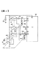
次に、図2は、本発明による防水型パワーウインド装置の第2実施例の要部構成を示す回路構成図である。
【0051】
図2において、図1に図示された構成要素と同じ構成要素については同じ符号を付けている。
【0052】
第2実施例は、第1実施例から自動ウインド上昇スイッチ5及び自動ウインド下降スイッチ6を省いているもので、自動ウインド上昇スイッチ5及び自動ウインド下降スイッチ6が接続されていない点を除けば、前記第1実施例の構成と同じである。このため、第2実施例の構成ついてはこれ以上の説明を省略する。
【0053】
また、第2実施例の動作における正常時(非浸水時)の動作については、ウインドを上昇及び下降させる際に、自動ウインド上昇スイッチ5及び自動ウインド下降スイッチ6を用いた自動(オート)操作を行なうことができない点を除けば、第1実施例の正常時の動作と殆んど同じである。このため、第2実施例の正常時の動作についてはこれ以上の説明を省略する。
【0054】
さらに、第2実施例の自動車内に浸水した時(非常時)の動作については、第1実施例の非常時の動作と全く同じであり、しかも、第2実施例が奏する作用効果については、非常時の動作が第1実施例の動作と同じであることから、第1実施例が奏する作用効果と同じである。このため、第2実施例の非常時の動作、及び、第2実施例が奏する作用効果についてはこれ以上の説明を省略する。
【0055】
なお、前記各実施例においては、水没検知素子が一対の導電金属パッド14であり、半導体検知素子がトランジスタ15である例を挙げて説明したが、本発明による水没検知素子や半導体検知素子は一対の導電金属パッドやトランジスタである場合に限られるものでなく、他の同機能を素子を用いても、同等の機能を発揮できることは勿論である。
【0056】
以上のように、本発明によれば、制御用集積回路の電源端子と接地端子との間に、制御端子に水没検知素子を接続した半導体検知素子を接続し、水没検知素子の水没検知時に半導体検知素子をオンにし、第1端子及び第2端子から電源電圧を出力させて、ウインドを上昇させる(閉じる)第1リレー及びウインドを下降させる(開く)第2リレーに供給するようにしているので、自動車が水中に落ち、防水型パワーウインド装置内に浸水したとき、露出した状態の水没検知素子がいち早く水没検知を行ない、直ちに半導体検知素子をオンにし、制御用集積回路の第1端子及び第2端子から電源電圧を出力し、第1リレー及び第2リレーにそれぞれ電源電圧を供給するようにしたので、この時点に、ウインドを上昇させる第1スイッチまたはウインドを下降させる第2スイッチを操作すれば、ウインドを上昇またはウインドを下降させることができるもので、特に、第2スイッチの操作によってウインドを下降させるようにすれば、水没中の自動車における開いたウインドから確実に車外に脱出することができ、既提案のこの種の防水型パワーウインド装置に比べて、安全性をより向上させることが可能になるという効果がある。
【図面の簡単な説明】
【図1】本発明による防水型パワーウインド装置の第1実施例の要部構成を示す回路図である。
【図2】本発明による防水型パワーウインド装置の第2実施例の要部構成を示す回路図である。
【図3】既知のパワーウインド装置の構成の一例を示す回路図である。
【図4】既提案されている防水型パワーウインド装置の要部構成の一例を示す回路図である。
【符号の説明】
1 ウインド上昇スイッチ(第1スイッチ)
2 ウインド上昇リレー
2C ウインド上昇リレー2の接点
3 ウインド下降スイッチ(第2スイッチ)
4 ウインド下降リレー
4C ウインド下降リレー4の接点
5 自動ウインド上昇スイッチ
6 自動ウインド下降スイッチ
7 第1逆流防止ダイオード
8 第2逆流防止ダイオード
9 第3逆流防止ダイオード
10 第4逆流防止ダイオード
11 ウインド開閉用モーター
12 制御用集積回路(制御IC)
13 車載電源(バッテリー)
14 一対の導電金属パッド(水没検知素子)
15 トランジスタ(半導体検知素子)
16、17 抵抗
18 ダイオード[0001]
BACKGROUND OF THE INVENTION
The present invention relates to a waterproof power window device, and in particular, when an automobile falls into water due to some cause, the waterproof power that can reliably open the door window by operating the window lowering switch. It relates to window equipment.
[0002]
[Prior art]
Generally, power window devices used in automobiles are submerged in the window up switch and window down switch when the automobile falls into the water, and it is difficult to maintain an electrical insulation state between the contact points of these switches. Even though the contacts of the window raising switch and window lowering switch are open, these contacts are electrically connected through a relatively small resistance value. Thereafter, the window lowering switch is operated. However, the window lowering operation, that is, the window opening operation cannot be performed.
[0003]
FIG. 3 is a circuit diagram showing an example of a circuit configuration of a main part of such a known power window device.
[0004]
As shown in FIG. 3, the power window device includes a
[0005]
A
[0006]
The power window device having the above-described configuration generally operates as follows.
[0007]
When a driver or the like operates the
[0008]
When a driver or the like operates the automatic
[0009]
Similarly, when the automatic
[0010]
By the way, the known power window device has a relatively resistance value due to water between the contacts of the
[0011]
In order to solve such a problem, the present applicant has a first series circuit composed of a first switch having one circuit and two contacts, one end of which is selectively connected to an in-vehicle power source or a ground point, and a first relay, A second series circuit consisting of a second switch and a second relay, one end of which is selectively connected to an in-vehicle power source or a ground point, and a control integrated circuit are provided, and the other end of the first series circuit is a second switch and a second relay. The other end of the second series circuit is connected to the connection point of the first switch and the first relay, and the first relay is energized by switching the contact of the first switch to rotate the motor in one direction. We have already proposed a waterproof power window device that drives and raises the window, and energizes the second relay by switching the contact of the second switch to drive the motor to rotate in the other direction and lower the window. Applicant 9-33 And it filed as No. 728.
[0012]
Here, FIG. 4 is a circuit configuration diagram showing the configuration of the proposed waterproof power window device.
[0013]
As shown in FIG. 4, the waterproof power window device includes a
[0014]
The movable contact of the
[0015]
The waterproof power window device having the above-described configuration generally operates as follows.
[0016]
When a driver or the like operates the
[0017]
On the other hand, when a driver or the like operates the
[0018]
When a driver or the like operates the automatic
[0019]
Similarly, when a driver or the like operates the automatic
[0020]
In addition, if the window is completely closed or close to being fully closed and the car falls into water for any reason, this waterproof power window device installed inside the door will also be submerged. It becomes a state. Although most of the components of the waterproof power window device are waterproofed, the
[0021]
In such a state, when a driver or the like operates the
[0022]
[Problems to be solved by the invention]
The waterproof power window device according to the above proposal can open the window by operating the
[0023]
As described above, the waterproof power window device according to the above proposal cannot reliably open the window even if the window lowering switch is operated when the automobile falls into water and the waterproof power window device is in a flooded state. ,It is difficult to ensure the reliability of the operation of the waterproof power window deviceQuestionHave a title.
[0024]
The present invention solves these problems, and its purpose is to quickly detect the inundation of the waterproof power window device and immediately shift to a state capable of responding to the inundation by the detection.reliableThe object is to provide a waterproof power window device.
[0025]
[Means for Solving the Problems]
In order to achieve the above object, the waterproof power window device of the present invention is configured such that the drive end of the first relay in the first series circuit is the first terminal of the control integrated circuit and the second relay is driven in the second series circuit. An end is connected to the second terminal of the control integrated circuit, and a semiconductor detection element having a submergence detection element connected to the control terminal is connected between the power supply terminal and the ground terminal of the control integrated circuit. Means is provided for turning on the semiconductor detecting element when the submergence detecting element is submerged by flooding and outputting a power supply voltage from the first terminal and the second terminal of the control integrated circuit.
[0026]
According to the above means, when the automobile falls into the water and is immersed in the waterproof power window device, the submergence detection element quickly detects submergence before the entire waterproof power window device is submerged. Is turned on, the power supply voltage is output from the first terminal and the second terminal of the control integrated circuit, and the power supply voltage is supplied to the first relay that raises (closes) the window and the second relay that lowers (opens) the window, respectively. Therefore, at this time, by operating the first switch for raising the window or the second switch for lowering the window, the window can be raised or lowered, and in particular, the second switch The window is lowered by the operation, and it is possible to reliably escape from the opened window.
In order to achieve the above object, the waterproof power window device of the present invention includes a first switch, a second switch, and a submergence detection element connected to each other, and the submergence detection element detects water intrusion.SecondA control unit is provided for controlling the window to be opened by operating the switch.
According to this means, it is possible to quickly detect water intrusion into the waterproof power window device and immediately shift to a state in which it is possible to cope with water immersion by the detection.
[0027]
DETAILED DESCRIPTION OF THE INVENTION
In an embodiment of the present invention, a waterproof power window device includes a first series circuit composed of a first switch and a first relay having one circuit and two contacts, one end of which is selectively connected to an in-vehicle power source or a ground point. Comprises a second series circuit consisting of a second switch and a second relay of one circuit and two contacts that are selectively connected to an on-vehicle power supply or a grounding point, an integrated circuit for control,The first switch of the first relay is not connectedThe other end is the connection point of the second switch and the second relayIs connected to the first switch of the first relayConnected to the first terminal of the control integrated circuit;The second switch of the second relay is not connectedThe other end is the connection point of the first switch and the first relayIs connected to the second switch of the second relay.Connected to the second terminal of the control integrated circuit, the first relay is energized by switching the contact of the first switch to drive the motor to rotate in one direction, the window is raised, and the second switch is switched to switch the second switch. 2 The relay is energized to rotate the motor in the other direction and lower the window. The integrated circuit for control has a submergence detection element connected to the control terminal between the power supply terminal and the ground terminal. A semiconductor detection element is connected, and when the submersion detection element detects submersion, the semiconductor detection element is turned on, and a power supply voltage is output from the first terminal and the second terminal.
[0028]
In the specific example of the embodiment of the present invention, in the waterproof power window device, the semiconductor detection element is formed of a transistor.
[0029]
In another specific example of the embodiment of the present invention, the waterproof power window device is composed of a pair of conductive metal pads in which the submergence detecting elements are arranged in an exposed state at a minute interval.
[0030]
According to these embodiments of the present invention, between the power supply terminal and the ground terminal of the control integrated circuit, a semiconductor detection element having a submergence detection element connected to the control terminal is connected, and when the submergence detection element detects submersion. The semiconductor detection element is turned on, the power supply voltage is output from the first terminal and the second terminal, and supplied to the first relay that raises (closes) the window and the second relay that lowers (opens) the window. Therefore, when the automobile falls into the water and is immersed in the waterproof power window device, the exposed submergence detection element quickly detects submergence, immediately turns on the semiconductor detection element, and the first terminal of the control integrated circuit and Since the power supply voltage is output from the second terminal and the power supply voltage is supplied to the first relay and the second relay, the first switch for raising the window at this point is used. Alternatively, if the second switch for lowering the window is operated, the window can be raised or lowered. In particular, if the window is lowered by the operation of the second switch, it can be opened in a submerged car. It is possible to escape from the vehicle with certainty.
In the embodiment of the present invention, the waterproof power window device includes an in-vehicle power source, a motor for opening and closing the window, and a window manually.Closing actionTell the windClosing directionThe first switch that connects the in-vehicle power supply to the motor to be driven byOpening actionTell the windOpen directionWhen the second switch that connects the in-vehicle power source to the motor so as to be driven, the submergence detection element, the first switch, the second switch, and the submergence detection element are connected to each other, and the submergence detection element detects the ingress of water InSecondAnd a control unit that controls the window to be opened by operating the switch.
According to this embodiment of the present invention, it is possible to quickly detect water intrusion into the waterproof power window device and immediately shift to a state where it is possible to cope with water immersion by the detection.
[0031]
【Example】
Embodiments of the present invention will be described below with reference to the drawings.
[0032]
FIG. 1 is a circuit diagram showing the main configuration of a first embodiment of a waterproof power window device according to the present invention.
[0033]
As shown in FIG. 1, the waterproof power window device of the first embodiment includes a window raising switch (first switch) 1 composed of a switch with one circuit and two contacts, a
[0034]
The movable contact of the window raising switch 1, the third
[0035]
The automatic window raising switch 5 has a movable contact connected to the in-
[0036]
Further, the
[0037]
The waterproof power window device according to the first embodiment having the above-described configuration generally operates as follows.
[0038]
First, the operation of the automobile when it is normal (not flooded) will be described.
[0039]
When a driver or the like operates the window raising switch 1, the movable contact is switched from the normally closed contact side to the normally opened contact side, and the voltage of the on-
[0040]
On the other hand, when a driver or the like operates the
[0041]
When a driver or the like operates the automatic window raising switch 5, the window raising switch 1 is simultaneously operated in conjunction with the operation, the movable contact of the automatic window raising switch 5 is closed, and the movable contact of the window raising switch 1 is illustrated. Switches from the normally closed contact side to the normally open contact side. When the movable contact of the window raising switch 1 is switched to the normally open contact side, the voltage of the on-
[0042]
Similarly, when a driver or the like operates the automatic
[0043]
Next, the operation when the vehicle is flooded (emergency) will be described.
[0044]
If the automobile falls into the water for some reason and is submerged in the car, the waterproof power window device of the first embodiment attached to the inside of the door sequentially enters the water-immersed state. In this case, when water enters the window raising switch 1 and the
[0045]
When a driver or the like operates the
[0046]
In addition, prior to the above-described operation, the waterproof power window device of the first embodiment has been immersed in the pair of exposed
[0047]
Here, when a driver or the like operates the
[0048]
In this case, if the driver or the like operates the window raising switch 1 instead of operating the
[0049]
As described above, according to the waterproof power window device of the first embodiment, immediately after the automobile falls into water and the waterproof power window device is immersed in water, that is, water enters the
[0050]
Next, FIG. 2 is a circuit configuration diagram showing the main configuration of a second embodiment of the waterproof power window device according to the present invention.
[0051]
In FIG. 2, the same components as those illustrated in FIG.
[0052]
In the second embodiment, the automatic window raising switch 5 and the automatic
[0053]
Further, regarding the normal operation (non-water-immersion) operation of the second embodiment, when the window is raised and lowered, an automatic operation using the automatic window raising switch 5 and the automatic
[0054]
Furthermore, the operation when the vehicle is submerged in the automobile of the second embodiment (emergency) is exactly the same as the operation of the emergency of the first embodiment, and the operational effects of the second embodiment are as follows: Since the operation at the time of emergency is the same as the operation of the first embodiment, it is the same as the operational effect of the first embodiment. For this reason, further description of the operation in the emergency of the second embodiment and the operational effects of the second embodiment will be omitted.
[0055]
In each of the above embodiments, the submergence detection element is a pair of
[0056]
As described above, according to the present invention, between the power supply terminal and the ground terminal of the control integrated circuit, the semiconductor detection element in which the submersion detection element is connected to the control terminal is connected. Since the detection element is turned on and the power supply voltage is output from the first terminal and the second terminal, the first relay that raises (closes) the window and the second relay that lowers (opens) the window are supplied. When the automobile falls into water and is immersed in the waterproof power window device, the exposed submergence detection element quickly detects submergence, immediately turns on the semiconductor detection element, the first terminal of the control integrated circuit and the second terminal Since the power supply voltage is output from the two terminals and the power supply voltage is supplied to the first relay and the second relay, the first switch or window for raising the window at this point is used. If the second switch for lowering the window is operated, the window can be raised or lowered. In particular, if the window is lowered by operating the second switch, the window is opened in a submerged car. As a result, it is possible to surely escape from the window to the outside of the vehicle, and the safety can be further improved as compared with the proposed waterproof power window device of this type.
[Brief description of the drawings]
FIG. 1 is a circuit diagram showing a main configuration of a first embodiment of a waterproof power window device according to the present invention.
FIG. 2 is a circuit diagram showing a main configuration of a second embodiment of the waterproof power window device according to the present invention.
FIG. 3 is a circuit diagram showing an example of a configuration of a known power window device.
FIG. 4 is a circuit diagram showing an example of a configuration of a main part of a previously proposed waterproof power window device.
[Explanation of symbols]
1 Window lift switch (1st switch)
2 Wind rising relay
Contact of 2C
3 Window lowering switch (second switch)
4 Wind lowering relay
Contact point of 4C window lowering relay 4
5 Automatic window lift switch
6 Automatic window lowering switch
7 First backflow prevention diode
8 Second backflow prevention diode
9 Third backflow prevention diode
10 4th backflow prevention diode
11 Wind open / close motor
12 Integrated circuit for control (control IC)
13 On-vehicle power supply (battery)
14 A pair of conductive metal pads (submergence detection element)
15 Transistor (Semiconductor sensing element)
16, 17 resistance
18 Diode
Claims (4)
Priority Applications (5)
| Application Number | Priority Date | Filing Date | Title |
|---|---|---|---|
| JP01155798A JP3765451B2 (en) | 1998-01-23 | 1998-01-23 | Waterproof power window device |
| EP19990300390 EP0931899B1 (en) | 1998-01-23 | 1999-01-20 | Power window device and a control device used for the same |
| DE69906402T DE69906402T2 (en) | 1998-01-23 | 1999-01-20 | Power window drive device and control device therefor |
| KR1019990001791A KR100315733B1 (en) | 1998-01-23 | 1999-01-21 | Power window device and controller thereof |
| US09/235,633 US6060794A (en) | 1998-01-23 | 1999-01-22 | Power window device and a control device used for the same |
Applications Claiming Priority (1)
| Application Number | Priority Date | Filing Date | Title |
|---|---|---|---|
| JP01155798A JP3765451B2 (en) | 1998-01-23 | 1998-01-23 | Waterproof power window device |
Publications (2)
| Publication Number | Publication Date |
|---|---|
| JPH11208265A JPH11208265A (en) | 1999-08-03 |
| JP3765451B2 true JP3765451B2 (en) | 2006-04-12 |
Family
ID=11781253
Family Applications (1)
| Application Number | Title | Priority Date | Filing Date |
|---|---|---|---|
| JP01155798A Expired - Fee Related JP3765451B2 (en) | 1998-01-23 | 1998-01-23 | Waterproof power window device |
Country Status (1)
| Country | Link |
|---|---|
| JP (1) | JP3765451B2 (en) |
-
1998
- 1998-01-23 JP JP01155798A patent/JP3765451B2/en not_active Expired - Fee Related
Also Published As
| Publication number | Publication date |
|---|---|
| JPH11208265A (en) | 1999-08-03 |
Similar Documents
| Publication | Publication Date | Title |
|---|---|---|
| KR100315733B1 (en) | Power window device and controller thereof | |
| JP3461432B2 (en) | Power window device | |
| JP3756718B2 (en) | Water resistant power window device | |
| US6459168B1 (en) | Power window mechanism for enabling window to be opened in case of submergence of vehicle | |
| EP0921256B1 (en) | Waterproof power window device | |
| JP2000154682A (en) | Power window device | |
| JP7113736B2 (en) | Opening/closing body control device | |
| JP3765451B2 (en) | Waterproof power window device | |
| JP3779467B2 (en) | Water resistant power window device | |
| JP3779466B2 (en) | Water resistant power window device | |
| JP3779468B2 (en) | Water resistant power window device | |
| JP2001010425A (en) | Detecting device for submergence of vehicle | |
| JP4047757B2 (en) | Power window device | |
| JP3602955B2 (en) | Waterproof power window device | |
| JP3461438B2 (en) | Waterproof power window device | |
| JP2004339708A (en) | Power window device | |
| JP2001020601A (en) | Electric load driving controller | |
| JP3461437B2 (en) | Waterproof power window device | |
| JP2002276241A (en) | Power window device with submergence sensor | |
| JP3803468B2 (en) | Power window device | |
| JP2006118263A (en) | Power-window switch circuit | |
| JP3535350B2 (en) | Power window device | |
| JP3949837B2 (en) | Power window device | |
| JP3703084B2 (en) | Power window device with submergence sensor | |
| JPH11262291A (en) | Window glass elevating equipment of vehicle |
Legal Events
| Date | Code | Title | Description |
|---|---|---|---|
| A621 | Written request for application examination |
Free format text: JAPANESE INTERMEDIATE CODE: A621 Effective date: 20031215 |
|
| A521 | Written amendment |
Free format text: JAPANESE INTERMEDIATE CODE: A523 Effective date: 20040213 |
|
| A521 | Written amendment |
Free format text: JAPANESE INTERMEDIATE CODE: A523 Effective date: 20040309 |
|
| A977 | Report on retrieval |
Free format text: JAPANESE INTERMEDIATE CODE: A971007 Effective date: 20050920 |
|
| A131 | Notification of reasons for refusal |
Free format text: JAPANESE INTERMEDIATE CODE: A131 Effective date: 20051004 |
|
| A521 | Written amendment |
Free format text: JAPANESE INTERMEDIATE CODE: A523 Effective date: 20051201 |
|
| TRDD | Decision of grant or rejection written | ||
| A01 | Written decision to grant a patent or to grant a registration (utility model) |
Free format text: JAPANESE INTERMEDIATE CODE: A01 Effective date: 20060110 |
|
| A61 | First payment of annual fees (during grant procedure) |
Free format text: JAPANESE INTERMEDIATE CODE: A61 Effective date: 20060119 |
|
| R150 | Certificate of patent or registration of utility model |
Free format text: JAPANESE INTERMEDIATE CODE: R150 |
|
| FPAY | Renewal fee payment (event date is renewal date of database) |
Free format text: PAYMENT UNTIL: 20090203 Year of fee payment: 3 |
|
| FPAY | Renewal fee payment (event date is renewal date of database) |
Free format text: PAYMENT UNTIL: 20100203 Year of fee payment: 4 |
|
| FPAY | Renewal fee payment (event date is renewal date of database) |
Free format text: PAYMENT UNTIL: 20100203 Year of fee payment: 4 |
|
| FPAY | Renewal fee payment (event date is renewal date of database) |
Free format text: PAYMENT UNTIL: 20110203 Year of fee payment: 5 |
|
| FPAY | Renewal fee payment (event date is renewal date of database) |
Free format text: PAYMENT UNTIL: 20120203 Year of fee payment: 6 |
|
| FPAY | Renewal fee payment (event date is renewal date of database) |
Free format text: PAYMENT UNTIL: 20120203 Year of fee payment: 6 |
|
| FPAY | Renewal fee payment (event date is renewal date of database) |
Free format text: PAYMENT UNTIL: 20130203 Year of fee payment: 7 |
|
| LAPS | Cancellation because of no payment of annual fees |