JP3765397B2 - Thermal transfer printer - Google Patents
Thermal transfer printer Download PDFInfo
- Publication number
- JP3765397B2 JP3765397B2 JP2001281529A JP2001281529A JP3765397B2 JP 3765397 B2 JP3765397 B2 JP 3765397B2 JP 2001281529 A JP2001281529 A JP 2001281529A JP 2001281529 A JP2001281529 A JP 2001281529A JP 3765397 B2 JP3765397 B2 JP 3765397B2
- Authority
- JP
- Japan
- Prior art keywords
- cassette
- ribbon cassette
- ribbon
- side plate
- head
- Prior art date
- Legal status (The legal status is an assumption and is not a legal conclusion. Google has not performed a legal analysis and makes no representation as to the accuracy of the status listed.)
- Expired - Fee Related
Links
- 239000000758 substrate Substances 0.000 claims description 22
- 238000010438 heat treatment Methods 0.000 claims description 6
- 238000001125 extrusion Methods 0.000 claims description 2
- 230000000717 retained effect Effects 0.000 claims 1
- 238000004804 winding Methods 0.000 description 12
- 238000003780 insertion Methods 0.000 description 4
- 230000037431 insertion Effects 0.000 description 4
- 238000005452 bending Methods 0.000 description 2
- 238000010586 diagram Methods 0.000 description 2
- 230000000694 effects Effects 0.000 description 2
- 230000014759 maintenance of location Effects 0.000 description 2
- 239000002184 metal Substances 0.000 description 2
- 239000011347 resin Substances 0.000 description 2
- 229920005989 resin Polymers 0.000 description 2
- 239000000853 adhesive Substances 0.000 description 1
- 230000001070 adhesive effect Effects 0.000 description 1
- 238000009434 installation Methods 0.000 description 1
Images


Landscapes
- Impression-Transfer Materials And Handling Thereof (AREA)
Description
【0001】
【発明の属する技術分野】
本発明は熱転写プリンタに係わり、カセット装着部に装着したリボンカセットをイジェクト機構にて外部に排出可能にした熱転写プリンタに関する。
【0002】
【従来の技術】
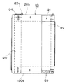
従来の熱転写プリンタには、図12に示すように、内部が空洞の箱状に形成されたフレーム101が配設されている。
このフレーム101には、手前側に一方の側板部101aと、この一方の側板部101aと対向する側に他方の側板部101bとがそれぞれ形成されている。また、フレーム101の上部には天板部101cが形成され、フレーム101の下部には底板部101dが形成されている。
このようなフレーム101内には、後述するリボンカセット119を着脱可能なカセット装着部102を有し、一方の側板部101aにリボンカセット119を挿入可能な着脱口102aが形成されている。
【0003】
他方の側板部101bには、回転可能な巻取りボビン103が配設され、この巻取りボビン103にリボンカセット119の一部が係合可能となっている。
図13に示すように、上記天板部101cには、角孔101fと、図示右側端面の一部を切欠いた切欠き部101gとがそれぞれ形成されている。
また、図12に示す側板部101a、101b間には、回転自在なプラテンローラ104が軸支されている。
【0004】
さらに他方の側板部101bには、ヘッド取付台107が片持ち支持されて取り付けられている。
上記ヘッド取付台107の下方には、プラテンローラ104と対向して複数の発熱素子を有するサーマルヘッド106が固着されている。
【0005】
カセット装着部102の下部には、後述する記録用紙127を案内可能な用紙ガイド板108が配設され、この用紙ガイド板108の図示左側に給排紙口108bが設けられて、内部のカセット装着部102に通じるようになっている。
【0006】
図14、図15A、15Bに示すように、壁部材109は、フック状の支持部109aと、支持部109aの図示左側に形成した貫通孔109bとを有していて、図12に示すカセット装着部102の図示左側を開閉するように配設されている。
さらに、図15Bに示すように、壁部材109は、湾曲状の側面109cが形成され、この側面109cがカセット装着部102の内壁面の一部を構成するようになっている。壁部材109の図15Aの右端部寄りの下部には、バネ係止部109dが突出形成されている。
【0007】
図14に示すように、第1イジェクトレバー110は、平坦部10aと、この平坦部10aの左端部が略直角に折り曲げられたカセット当接部110bとから形成されている。
平坦部110aの右端部には、バネ係止部110cが形成され、平坦部110aの上下端部には一対のストッパー部110dが折り曲げ形成されている。
そして、第1イジェクトレバー110は、バネ係止部110cと壁部材109のバネ係止部109dとの間にコイルばね111が係止されて、図示の矢印G方向に弾性付勢されている。
【0008】
図12に示すように、一方の側板部101aには、スライド部材114が配設され、このスライド部材114によってカセット装着部102からリボンカセット119を抜け出す方向(図12の紙面と直交する方向)への動きを止めるようになっている。
上記スライド部材114は、中央に一方の側板部101aから突出するプラテン駆動軸105を回避する逃げ孔114aが形成され、この逃げ孔114aの左側端部にテーパー状のカセット当接部114bが形成されている。
上記スライド部材114の右側側壁114dには、右方向に突出する細長状をした押圧部114eが形成されている。そして、スライド部材114は、着脱口102aの一部を遮るように矢印E、F方向に往復動するようになっている。
上記スライド部材114は、通常コイルバネによって矢印E方向に弾性付勢され、着脱口102aの一部を遮るようになっている。
【0009】
図13に示すように、フレーム101の角孔101fには、イジェクト機構の一部を構成する第2イジェクトレバー115が取り付けられている。
上記第2イジェクトレバー115は、一端にカセット押圧部115cが折り曲げ形成され、他端に駆動部115eが斜めに折り曲げ形成されている。
そして、第2イジェクトレバー115は、カセット押圧部115cを切欠き部101gに位置させ、駆動部115eをフレーム101の空洞部内に位置させるように、リベット116を支点として天板部101cに回動自在に取り付けられている。
【0010】
図12に示すように、一方の側板部101aには、第2イジェクトレバー115を回動するための回動レバー117が配設されている。
この回動レバー117はリベット118で一方の側板部101aの内側に回動自在に取り付けられて、スライド部材114の押圧部114eが回動レバー117の一方端に当接し、第2イジェクトレバー115の駆動部115eが回動レバー117の他方端に当接するようになっている。
【0011】
図16及び図17に示すように、この熱転写プリンタに使用するリボンカセット119は、内部に空洞部を有するカセット本体部120と、このカセット本体部120から一方側に延出形成されたリボン案内部121とから主に構成されている。
カセット本体部120の空洞部内には、インクリボン122が収納されている。
インクリボン122は、両端が供給コア123と巻取りコア124とにそれぞれ巻回されていて、これら供給コア123、巻取りコア124がカセット本体部120の側壁120a、120b間に回転自在に軸支されている。
また、一方の側壁120bの右側端部には抜止め部120dが形成され、この抜止め部120dにスライド部材114のカセット当接部114bが当接してリボンカセット119をカセット装着部102から抜け止めするようになっている。
【0012】
リボン案内部121の下部には、ヘッド取付台107を挿入可能なヘッド挿入部125が形成されている。
図17に示すリボン案内部121の上部には凸部126が形成されてフレーム101の切欠き部101gに嵌合するようになっている。
【0013】
このような熱転写プリンタにリボンカセット119を着脱する動作を説明すると、先ず、図16に示すリボンカセット119を他方の側壁部120b側から図12に示すフレーム101の着脱口102aに挿入すると、抜止め部120dによって着脱口102aの一部を遮るようになっていたスライド部材114が、図12の矢印F方向に移動してリボンカセット119は、カセット装着部102に装着される。
すると、スライド部材114が矢印E方向に移動して、カセット装着部102から抜け出す方向へのリボンカセット119の抜け止め動作を抜止め部120dで阻止する。
このとき、第1イジェクトレバー110は、カセット当接部110bが他方の側壁120bに押されて、コイルばね111の付勢力に抗して図14の矢印H方向に移動する。
【0014】
次に、カセット装着部102に装着したリボンカセット119をスライド部材114による抜け止めを解除して、カセット装着部102から排出するには、先ず、スライド部材114を手動操作で図12に示す矢印F方向に移動させる。
すると、リボンカセット119の抜止め部120dからスライド部材114のカセット当接部114bが外れて、スライド部材114からなる抜け止めが解除される。
【0015】
このようにスライド部材114を矢印F方向に移動させる動作で、押圧部114eが回動レバー117の一端を押圧することで、回転レバー117の他端が第2イジェクトレバー115の駆動部115eを押圧して、第2イジェクトレバー115がリベット116を支点として図13の反時計回り方向に回動する。
【0016】
続いて、カセット押圧部115cが切欠き部101gに位置しているリボンカセット119の凸部126を押圧して、リボンカセット119が着脱口102aからその一部が排出される。
続いて、第1イジェクトレバー110は、スライド部材114の抜け止めが解除されると、コイルばね111の作用で図14の矢印G方向に移動して、カセット押圧部115cがリボンカセット119の他方の側壁120bを押圧して、リボンカセット119をカセット装着部102から外部に排出する。
【0017】
【発明が解決しようとする課題】
ところで、このように構成され、動作する従来の熱転写プリンタでは、イジェクト機構が上述したように第1イジェクトレバー110や第2イジェクトレバー115などの複雑な機構部品からなり、しかもその部品点数が多くなるため、組み立てが難しいという問題があった。
【0018】
また、コイルばね111によって常に図13に示す矢印G方向への弾性付勢力で、スライド部材114のカセット当接部114bで押さえつけているので、スライド部材114のカセット当接部114bが何らかの条件で抜止め部121dから解除されてしまうと、リボンカセット119が着脱口から勢いよく飛び出してしまい、外部に露出したインクリボン122の一部を傷付けたり、リボンカセット119のカセット本体部120そのものを破損してしまうおそれがあった。
【0019】
本発明の熱転写プリンタは、部品点数の少ない簡単な構造で、カセット装着部に装着されたリボンカセットのロック解除にともなって、スムーズに排出することができるようにしたことを目的とする。
【0020】
【課題を解決するための手段】
上記課題の少なくとも1つを解決するための第1の解決手段として、インクリボンをカセット本体部に収納したリボンカセットと、互いに対向する一対の側板部と一方の前記側板部に形成した開口部から挿入される前記リボンカセットを着脱可能なカセット装着部とを有するフレームと、他方の前記側板部に取付けて前記カセット装着部内に位置させたサーマルヘッドと、前記カセット装着部に装着した前記リボンカセットを抜け止め可能な抜け止め部と、前記抜け止め部で抜け止めされた前期リボンカセットをロック及びロック解除可能なイジェクト部材と、を備え、
前記カセット装着部内に装着した前記リボンカセットを前記開口部方向へ所定の付勢力で付勢する付勢部材を前記フレームに取り付けして、前記一方の側板部に沿ってスライド移動させて前記イジェクト部材が前記リボンカセットのロック解除を行うことにより、前記リボンカセットの抜け止めが解除されて、前記カセット装着部に装着された前記リボンカセットを、前記付勢部材の付勢力にて前記カセット装着部から押出し移動可能にした熱転写プリンタであって、
前記リボンカセットの上面には、前記イジェクト部材に形成した係合溝に係合可能な係合部を突出形成し、前記イジェクト部材は、前記一方の側板部に沿って配設した基板部と、前記フレームの上面に沿って前記基板部に対し略直角に形成した摺接板部とを設け、前記摺接板部は、前記係合溝に係合した前記リボンカセットの係合部に摺接しながら前記前記リボンカセットを前記開口部から排出可能とした傾斜部を形成したものである。
【0021】
また、第2の解決手段として、前記フレーム上面の前記開口部側の縁部には切欠き溝を形成して、前記リボンカセットの前記係合部を前記切欠き溝にガイドされて前記リボンカセットを前記開口部から排出するようにしたものである。
【0022】
また、第3の解決手段として、前記リボンカセットは、前記カセット本体部の上面から延出して一体形成されたリボン案内部を有し、該リボン案内部の下面には前記サーマルヘッドと対向配置可能なヘッド当接部を設けて、
前記サーマルヘッドは、複数の発熱素子を有する基板部と、該基板部を固着し、前記他方の側板部に取付けしたヘッド取付台とを有し、前記抜止め部は、前記ヘッド取付台の先端を湾曲させてフック状に形成し、前記リボンカセットは、前記ヘッド当接部に前記抜け止め部と係合可能なリブ部を形成したものである。
【0024】
【発明の実施の形態】
本発明の一実施形態である熱転写プリンタを図1乃至図11に基づいて以下に説明する。
熱転写プリンタは、図1に示すように、内部に空洞部を有する箱状からなり、手前側および後方側に互いに対向して配置された一対の側板部1a、1bと、上方側に天板部1cと、下方側に底板部1dとを有するフレーム1を備えている。
このフレーム1は、空洞部内に後述するリボンカセットを装着可能なカセット装着部2を設け、このカセット装着部2にリボンカセットを着脱するための開口部2aが一方の側板部1aに形成されている。
【0025】
他方の側板部1bの外側には、モータ4とこのモータ4の駆動力を伝達するギヤ群5とが取り付けられていて、この他方の側板部1bの図2の右側には、貫通形成された丸孔(図示せず)から円柱状をした巻取りボビン8がギヤ群5の一部と連結して回転可能に取り付けられている。
さらに他方の側板部1bには、巻取りボビン8に近接して位置決め孔1eが貫通形成され、図2の右端部には凹部1mが切欠き形成されている。
カセット装着部2内の底板部1d上には、一部を斜めに形成した樹脂製の傾斜台部2b(図5参照)が取り付けられていて、後述する記録用紙40(図11参照)を搬送するためのガイドとなっている。
図2に示すように、天板部1cの裏面には、その端部側を略直角に折り曲げてカセット装着部2内に突起1kが突出形成されている。
【0026】
図1に示すように、フレーム1の一方の側板部1aには、その表面に沿って図1の右方向にスライド移動可能なイジェクト部材(イジェクト機構)3が小バネ3t(図2参照)を介して取り付けられている。
このイジェクト部材3は、樹脂製又は金属製から成り、平面視L字状に形成された基板部3aと、この基板部3aの一部と略直角に折り曲げて天板部1c上を摺接する摺接板部3bとから構成されている。
なお、摺接板部3bは、基板部3aとともにあらかじめL字状に樹脂にて一体成形したものであってもよい。
【0027】
上記基板部3aは、その表面に滑り止め用の滑り止め部3dが形成されていて、この滑り止め部3d近傍の端面を斜めにカットした傾斜部3eが形成されている。そして、これら滑り止め部3d及び傾斜部3eにより、このイジェクト部材3を手動で操作する際にスムーズに操作できるようになっている。
さらに基板部3aには、一方の側板部1aの開口部2aを開放する部分に開放部3gを有し、この開放部3gにより摺接板部3bとの間に所定の空間を形成している。
【0028】
イジェクト部材3の摺接板部3bは、その中央に略細長状の孔部3fが貫通形成されていて、この孔部3f内には天板部1c上からプレス加工等にて僅かに突出形成された2個の突き出し部1fが嵌合し、突き出し部1fにガイドされながらイジェクト部材3全体が図1の矢印E、F方向にスライド移動するようになっている。
また、摺接板部3bの開放部3g側の縁部には、切欠き加工された係合溝3hが形成され、この係合溝3hの図示左側にはイジェクト部材3の矢印E、F方向のスライド移動方向に対して斜めに切欠き加工された傾斜部3kが形成されている。
なお、開口部2aの一部を構成する天板部1cの縁部には、所定深さの切欠き溝1hが形成され、この切欠き溝1hにイジェクト部材3の係合溝3hが位置するようになっている。
そして、この切欠き溝1h内には、後述するリボンカセットの突部が係合するようになっている。
【0029】
図2及び図3に示すように、フレーム1の両側板部1a、1b間には軸部材6が軸支され、この軸部材6と平行に回転自在なプラテンローラ9がその両端を支持レバー11を介して軸支されている。
上記支持レバー11は、両端側を略直角に折り曲げた一対の対向する腕部11bを有し、腕部11bに略U字状に切り欠いた係止溝11fが形成され、コイルバネ11gにてこの係止溝11f内にプラテンローラ9の回転軸の両端が摺動可能に支持されている。
【0030】
次に、図2及び図3に示すように、熱転写プリンタの側方側(図2の左側)には、金属棒等からなる紙送りローラ13と、この紙送りローラ13に圧接する圧接ローラ14とが、両側板部1a、1bに回転自在に取り付けられている。
そして、紙送りローラ13および圧接ローラ14にて挟持される記録用紙40(図11参照)は、図2の左右方向に紙送りされるようになっている。
【0031】
次に、図2に示すように、付勢部材であるコイルばね30は、コイル状に巻回して形成された巻線部30aと、巻線部30aの両端から延設された一方の延設部30b、他方の延設部30cとを有し、巻線部30aをフレーム1の突起1kに係合している。
一方の延設部30bは、略くの字状をした弾性付勢力を有する線材であり、その先端を略直角に折り曲げてカセット当接部30dを形成している。
他方の延設部30cは、他方の側板部1bの凹部1m内に係合して、この延設部30cおよび巻線部30aによりコイルばね30全体がフレーム1に固定されるとともに、一方の延設部30bのカセット当接部30dがカセット装着部2に装着した後述するリボンカセットを弾性付勢力により押し出し可能となっている。
【0032】
次に、図4乃至図6に示すように、サーマルヘッド17は、複数の発熱素子を有する基板部18と、この基板部18を固着し、フレーム1の他方の側板部1bに取り付けしたヘッド取付台19とを有している。
そして、サーマルヘッド17は、プラテンローラ9と対向する位置に配設され、基板部18を接着剤等で固着した略四角状のヘッド取付台19が、フレーム1の側板部1bにねじ止め等により片持ち支持されて所定の弾性力を有した状態で取り付けられている。
上記ヘッド取付台19は、図6に示す右側の自由端である先端部19aがカセット装着部2の開口部2aから若干外方に突出している。
そして、このヘッド取付台19の先端部19aには、折り返し加工して2枚重ねにされ、湾曲、且つフック状をした抜止め溝(抜止め部)19fが形成されている。
【0033】
次に、図7乃至図10に示すように、リボンカセット35は、断面が略楕円形状をしたカセット本体部36と、このカセット本体部36から一方側(図7の右方向側)に延出して一体形成されたリボン案内部37とを有している。
【0034】
このカセット本体部36の空洞内部にはインクリボン39が収納され、このインクリボン39の両端部がカセット本体部36内に回転可能に収納された供給ローラ41と巻取りローラ42とに巻回されている。
また、リボンカセット35の一方の側壁36aの図2の手前側には直角状をしたイジェクト当接部36gが設けられている。
【0035】
リボン案内部37の下面には、平坦状をしたヘッド当接部37aが形成されていて、このヘッド当接部37aにヘッド取付台19の上面が当接するようになっている。
リボン案内部37の先端部には、回転自在な小ローラ38aを有するリボン折り返し部38が形成されている。
ヘッド当接部37aは、リボン折り返し部38側に小ローラ38aの軸心方向に沿って帯状をした弾性を有する長片部37bを立設形成している。
この長片部37bは、リボンカセット35をカセット装着部2内に挿入するにつれてヘッド取付台19の図10に示す左右側の側壁で徐々に弾圧するように嵌合する抜け止めの役割をしている。
【0036】
また、図2に示すように、リボン案内部37の下板37fの一部であるヘッド当接部37aには、僅かに突出させたリブ部37cが細長く形成され、リブ部37cがヘッド取付台19の抜止め部19fと係合可能となっている。
【0037】
リボン案内部37のヘッド当接部37aの下部空間(図2の上部)には、サーマルヘッド17を挿入可能なヘッド挿入部43が設けられている。
リボン案内部37の上板37eには、リボン折り返し部38の近傍で、インクリボン39の幅方向の一端部に四角状をした係合部である突部37gが図1の上方に突出して形成されている。この突部37gは、フレーム1の天板部1cの切欠き溝1h内に嵌合可能となっている。
また、カセット本体部36の他方の側壁36bには、巻取りローラ42の一端側に近傍して小突起36kが突出形成され、この小突起36kはリボンカセット35をカセット装着部2に装着したときにフレーム1の他方の側板部1bの位置決め孔1eと嵌合可能となっている。
【0038】
図11に示すように、記録用紙40は、図中の左側の図示しない給紙部から供給され、カセット装着部2にリボンカセット35を装着した状態で、用紙挿入口42aから挿入可能となっている。
用紙挿入口42aから挿入された記録用紙40は、リボンカセット35の下部を通過し、傾斜台部2bを経てプラテンローラ9とサーマルヘッド18との間に配設されたインクリボン39の下方側に搬送されて、紙送りローラ13と圧接ローラ14とに圧接挟持されるようになっている。
そして、紙送りローラ13と圧接ローラ14とに圧接挟持された記録用紙40は、紙送りローラ13の回転で外部に排紙可能となっている。
【0039】
次に、図1、図2および図11に基づいて、熱転写プリンタにリボンカセット35を挿着する動作を説明する。
先ず、リボンカセット35を他方の側壁36b側から先に一方の側板部1aの開口部2aに挿入すると、カセット装着部2内においてヘッド当接部37aがヘッド取付台19の上面(天板)に案内されて奧側に徐々に挿入される。
【0040】
徐々にリボンカセット35が挿入されることにより、その他方の側壁36bにコイルばね30のカセット当接部30dが当接し、さらにこのコイルばね30の弾性付勢力に抗してリボンカセット35を押し続けてカセット装着部2内の奥側に挿入していくと、ヘッド取付台19の側壁にてリボンカセット35の長片部37bが弾圧される。それとともに、ヘッド取付台19の抜止め部(抜止め溝)19fにリボンカセット35のリブ部37cが嵌合して、リボンカセット35がカセット装着部2から抜け止めされる。
このとき、位置決め孔1e内にリボンカセット35の小突起36kが嵌入され、巻取りボビン8にリボンカセット35の巻取りローラ42が回転可能に係合するとともに、リボンカセット35の突起37gがフレーム1の切り欠き溝1h内に係合して、リボンカセット35が位置決めされる。
【0041】
なお、イジェクト部材3は、その斜め形成された傾斜部3eがリボンカセット35のイジェクト当接部36gに当接して小ばね3tの弾性付勢力に抗しながら図示右方向(E方向)にスライド移動して、リボンカセット35がカセット装着部2内にほぼ収納されると同時に、イジェクト当接部36gが傾斜部3eから解除されて、イジェクト部材3が小ばね3tの弾性付勢力にて元の位置に戻る。
こうして、イジェクト部材3は、サーマルヘッド17の抜止め部19fで抜け止めしたリボンカセット35をカセット装着部2内にロックしてカセット装着部2から抜け出す方向の動きを規制する。
【0042】
次に、カセット装着部2内に装着されたリボンカセット35を取り出す動作を説明すると、先ず、イジェクト部材3の基板部3aを滑り止め部3d等を介して手操作にて図1の右側方向にスライド移動させる。すると、イジェクト部材3の傾斜部3eが一部遮蔽していた開口部2aをその部分から移動する。
このとき、イジェクト部材3の摺接板部3bの傾斜部3kがイジェクト部材3の移動に伴ってリボンカセット35の突起37gを重ね合う切欠き溝1h、係合溝3hから徐々に外部に排出しようとする。
【0043】
さらに、イジェクト部材3をスライド移動方向に強く動かすと、抜止め部19f内からリボンカセット35のリブ部37cが一旦抜けるとともに、コイルばね30の弾性付勢力によってリボンカセット35がカセット当接部30dで押圧され、開口部2aからリボンカセット35が所定量押し出されて外部に排出される。
このように、イジェクト部材3は、手動操作されることにより、ヘッド取付台19の抜止め溝19fで抜け止めされたリボンカセット35のリブ部37cを取り外すロック解除機能を有している。
【0044】
次に、熱転写プリンタによる記録用紙40への印字動作を図11に基づいて説明すると、先ず、プラテンローラ9をサーマルヘッド17から離間させる。
次に、この状態で、カセット装着部2内にリボンカセット35を装着すると、リボンカセット35は、サーマルヘッド17の抜止め部19fにて抜け止めされて装着される。
次に、記録用紙40を給排紙口42aから矢印M方向に挿入すると、記録用紙40は、プラテンローラ9と印字ヘッドであるサーマルヘッド17との隙間に位置するインクリボン39の下部を搬送され、記録用紙40の先端側が紙送りローラ13と圧接ローラ14とに圧接挟持される。
【0045】
次に、モータ4の駆動力をギヤ群5を介して伝達させることにより、プラテンローラ9を上方に移動させて、インクリボン39と記録用紙40とをサーマルヘッド17に圧接挟持する。
次に、この状態で紙送りローラ13を時計回り方向に回転させると、記録用紙40が上記矢印M方向に搬送されるとともに、サーマルヘッド17の複数の発熱素子を選択的に発熱させて記録用紙40にインクリボン39のインクを転写して所望の画像を印刷記録する。
【0046】
そして、印刷が終了すると、プラテンローラ9を下方に移動させるとともに、紙送りローラ12を反時計回り方向に回転させて、印刷記録された記録用紙40が矢印N方向に搬送される。
【0047】
以上のように構成され、動作する本発明の熱転写プリンタは、以下に示す効果を奏する。
1)カセット装着部2内に装着したリボンカセット35を開口部2a方向へ所定の付勢力で付勢するコイルばね30をフレーム1に取り付けて、一方の側板部1bに沿ってスライド移動させてイジェクト部材3のロック及びロック解除を行うことにより、リボンカセット35の抜け止めが解除され、カセット装着部2に装着されたリボンカセット35を、コイルばね30の所定の付勢力にてカセット装着部2から押出して移動可能にしたことにより、リボンカセット35をカセット装着部2から押し出して移動させるイジェクト機構を少ない部品点数にて簡単に構成することができる。そのため、組み立てが簡単であるとともに、熱転写プリンタの小型化・薄型化を達成することができる。
【0048】
2)リボンカセット35の上面には係合部である突部37gを形成して、イジェクト部材3は、一方の側板部1bに沿って配設した基板部3aと、フレーム1の上面に沿って基板部3aに対し略直角に折曲げ形成した摺接板部3bとをそれぞれ設けて、摺接板部3bには、リボンカセット35の突部37gに摺接し、リボンカセット35を開口部2aから外部に排出可能とした傾斜部3kが形成されたことにより、イジェクト部材3の傾斜部3kの形状に合わせてリボンカセット35の突部37gを移動させるので、一方向に僅かに押圧するだけでリボンカセット35を簡単に排出することができる。
【0049】
3)フレーム1上面の開口部2a側の縁部に係合溝3hを形成して、リボンカセット35の突部37gを係合溝3hにガイドされて排出するようにしたことにより、突部37gをイジェクト部材3で押圧する際に、係合溝3hに沿ってがたつきなくリボンカセット35を排出することができるので、露出したインクリボン39の一部を他に接触して損傷させることなく、スムーズに排出することができる。また、プリンタ本体から排出されたリボンカセット35はその後端部がコイルばね30によって支えられているため、プリンタ本体を立てた状態としても、リボンカセット35がプリンタ本体内部に落ち込むことがないので、カセット交換がスムーズに行うことができる。
【0050】
4)リボンカセット35は、カセット本体部36の上面から延出して一体形成されたリボン案内部37を有し、リボン案内部37の下面にはサーマルヘッド17と対向配置可能なヘッド当接部37aを設けて、サーマルヘッド17は、複数の発熱素子を有する基板部18と、基板部18を固着し、他方の側板部1bに取り付けしたヘッド取付台19とを有し、抜止め部である抜止め溝19fは、サーマルヘッド19の先端を湾曲させてフック状に形成したリブ部37cに係合可能にしたことにより、このリブ部37cによりリボンカセット35の抜止め部19fから確実に抜け止めすることができる。
【0051】
5)カセット本体部36は、一対の側壁36a、36bを有するとともに、一方の側壁36aを延設したイジェクト当接部36gを設けて、このイジェクト当接部36gをイジェクト部材3の傾斜部3eに当接させるようにしたことにより、リボンカセット35のカセット装着部2からの抜け止めを抜止め部19fとともにおこなうことにより、より確実に抜け止めする事ができる。そのため、リボンカセット35を落下して破損させることなく、より一層不測の抜け落ちを防止することができる。
【0052】
以上、本発明の一実施形態について説明してきたが、本発明は上記実施形態に限定されることはなく、その主旨を逸脱しない範囲内において変更して実施することができる。
例えば、リボンカセット35の突起37gを四角形状ではなく、摺接板部3bと摺接する部分を傾斜させた傾斜部をもたせて、一方の摺接板部3bの傾斜部3kを有する係合溝3hを単に矩形状にしたものであってもよい。
また、フレーム1の一方の側板部1aにイジェクト部材3のスライド移動用に一部を切り欠いて、摺接板部3bを天板部1cの下面に位置させても良い。
また、リボンカセット35の突起37gの代わりに凹部とし、係合するフレーム1の切欠き溝1hの代わりに下方に突出した突起であってもよい。
【0053】
【発明の効果】
以上のように説明してきた本発明の熱転写プリンタは、インクリボンをカセット本体部に収納したリボンカセットと、互いに対向する一対の側板部と一方の側板部に形成した開口部から挿入したリボンカセットを着脱可能なカセット装着部とを有するフレームと、他方の側板部に取付けてカセット装着部に位置させたサーマルヘッドと、カセット装着部に装着したリボンカセットを抜け止め可能な抜止め部と、抜止め部で抜け止めされたリボンカセットをロック及びロック解除可能なイジェクト部材と、を備え、カセット装着部内に装着したリボンカセットを開口部方向へ所定の付勢力で付勢する付勢部材をフレームに取り付けして、一方の側板部に沿ってスライド移動させてイジェクト部材のロック解除を行うことにより、リボンカセットの抜け止めが解除されて、カセット装着部に装着されたリボンカセットを、付勢部材の付勢力にてカセット装着部から押出して移動可能にしたことにより、リボンカセットをカセット装着部から押し出して移動させる機構を少ない部品点数にて簡単に構成することができ、しかも、その組み立てが容易である。
【図面の簡単な説明】
【図1】本発明の一実施形態である熱転写プリンタの斜視図である。
【図2】本発明の一実施形態である底板を外した熱転写プリンタの底面側から見た斜視図である。
【図3】本発明の一実施形態である熱転写プリンタの別の角度から見た斜視図である。
【図4】本発明の一実施形態である熱転写プリンタの正面図である。
【図5】本発明の一実施形態である熱転写プリンタの正面図である。
【図6】本発明の一実施形態である熱転写プリンタの側面図である。
【図7】本発明の一実施形態である熱転写プリンタに着脱可能なリボンカセットの正面図である。
【図8】図7におけるリボンカセットの底面図である。
【図9】図7におけるリボンカセットの平面図である。
【図10】本発明の一実施形態である熱転写プリンタにリボンカセットを装着した際のリボンカセットとヘッド取付台との位置関係を説明するための説明図である。
【図11】本発明の一実施形態である熱転写プリンタの縦断面図である。
【図12】従来の熱転写プリンタの正面図である。
【図13】従来の熱転写プリンタの平面図である。
【図14】従来の熱転写プリンタの左側面図である。
【図15】従来の熱転写プリンタの壁部材を説明するための説明図である。
【図16】従来の熱転写プリンタに着脱可能なリボンカセットの正面図である。
【図17】図16におけるリボンカセットの平面図である。
【符号の説明】
1 フレーム
1a 一方の側板部
1b 他方の側板部
1h 切欠き溝
2 カセット装着部
2a 開口部
3 イジェクト部材
3a 基板部
3b 摺接板部
3k 傾斜部
3h 係合溝
17 サーマルヘッド
18 基板部
19 ヘッド取付台
19f 抜止め溝(抜止め部)
30 コイルばね(付勢部材)
35 リボンカセット
36 カセット本体部
37 リボン案内部
37a ヘッド当接部
37c リブ部
37g 突起(係合部)
39 インクリボン[0001]
BACKGROUND OF THE INVENTION
The present invention relates to a thermal transfer printer, and more particularly to a thermal transfer printer in which a ribbon cassette mounted on a cassette mounting portion can be discharged to the outside by an eject mechanism.
[0002]
[Prior art]
As shown in FIG. 12, a conventional thermal transfer printer is provided with a
The
In such a
[0003]
A rotatable winding
As shown in FIG. 13, the
Further, a
[0004]
Further, a
Below the
[0005]
A
[0006]
As shown in FIGS. 14, 15A and 15B, the
Further, as shown in FIG. 15B, the
[0007]
As shown in FIG. 14, the
A
The
[0008]
As shown in FIG. 12, a
The
On the right side wall 114d of the
The
[0009]
As shown in FIG. 13, a
The
The
[0010]
As shown in FIG. 12, a
The rotating
[0011]
As shown in FIGS. 16 and 17, a
An
Both ends of the
Further, a
[0012]
A
A
[0013]
The operation of attaching / detaching the
Then, the
At this time, the
[0014]
Next, in order to release the
Then, the
[0015]
Thus, in the operation of moving the
[0016]
Subsequently, the
Subsequently, when the
[0017]
[Problems to be solved by the invention]
By the way, in the conventional thermal transfer printer configured and operated in this way, the eject mechanism is composed of complicated mechanism parts such as the
[0018]
Further, since the coil spring 111 is always pressed by the
[0019]
An object of the thermal transfer printer of the present invention is to have a simple structure with a small number of parts and to be able to smoothly discharge the ribbon cassette mounted on the cassette mounting portion when the ribbon cassette is unlocked.
[0020]
[Means for Solving the Problems]
As a first solving means for solving at least one of the above problems, a ribbon cassette storing an ink ribbon in a cassette body, a pair of side plates facing each other, and an opening formed in one of the side plates InsertBe doneA frame having a cassette mounting portion to which the ribbon cassette can be attached and detached, a thermal head attached to the other side plate portion and positioned in the cassette mounting portion, and the ribbon cassette mounted to the cassette mounting portion can be prevented from being detached. A retaining part, and an eject member capable of locking and unlocking the previous ribbon cassette secured by the retaining part,
A biasing member for biasing the ribbon cassette mounted in the cassette mounting portion with a predetermined biasing force in the direction of the opening is attached to the frame, and is slid along the one side plate portion to be the eject member. The release of the ribbon cassette is released by releasing the lock of the ribbon cassette, and the ribbon cassette mounted on the cassette mounting portion is removed from the cassette mounting portion by the biasing force of the biasing member. Enables extrusion movementA thermal transfer printer,
On the upper surface of the ribbon cassette, an engaging portion that can be engaged with an engaging groove formed in the eject member is formed to protrude, and the eject member includes a substrate portion disposed along the one side plate portion, A sliding contact plate portion formed at a substantially right angle with respect to the substrate portion is provided along the upper surface of the frame, and the sliding contact plate portion is in sliding contact with the engagement portion of the ribbon cassette engaged with the engagement groove. While forming an inclined portion that allows the ribbon cassette to be discharged from the opening.It is a thing.
[0021]
As a second solution, the above-mentionedA notch groove is formed at an edge of the upper surface of the frame on the opening side so that the engaging portion of the ribbon cassette is guided by the notch groove and the ribbon cassette is discharged from the opening.It is a thing.
[0022]
In addition, as a third solving means,The ribbon cassette has a ribbon guide portion integrally formed extending from the upper surface of the cassette main body, and a lower surface of the ribbon guide portion is provided with a head abutting portion that can be disposed opposite to the thermal head,
The thermal head includes a substrate portion having a plurality of heating elements, and a head mounting base that fixes the substrate portion and is attached to the other side plate portion, and the retaining portion is a tip of the head mounting base. The ribbon cassette is formed with a rib portion that can be engaged with the retaining portion at the head contact portion.It is a thing.
[0024]
DETAILED DESCRIPTION OF THE INVENTION
A thermal transfer printer according to an embodiment of the present invention will be described below with reference to FIGS.
As shown in FIG. 1, the thermal transfer printer has a box shape having a hollow portion therein, and a pair of side plate portions 1 a and 1 b disposed opposite to each other on the front side and the rear side, and a top plate portion on the upper side. 1c and a
The
[0025]
A
Further, a positioning hole 1e is formed through the other side plate portion 1b in the vicinity of the take-up
On the bottom plate portion 1d in the
As shown in FIG. 2, a projection 1 k is formed on the back surface of the top plate portion 1 c so as to protrude into the
[0026]
As shown in FIG. 1, on one side plate portion 1a of the
The
Note that the sliding
[0027]
The
Further, the
[0028]
The slidable
Further, a notch-engaged
A notch groove 1h having a predetermined depth is formed at the edge of the top plate portion 1c constituting a part of the
And the protrusion part of the ribbon cassette mentioned later engages in this notch groove 1h.
[0029]
As shown in FIGS. 2 and 3, a
The support lever 11 has a pair of opposing arm portions 11b that are bent at substantially right angles on both ends, and a locking groove 11f cut out in a substantially U shape is formed in the arm portion 11b. Both ends of the rotating shaft of the
[0030]
Next, as shown in FIGS. 2 and 3, on the side of the thermal transfer printer (on the left side in FIG. 2), a
The recording paper 40 (see FIG. 11) sandwiched between the
[0031]
Next, as shown in FIG. 2, the
One extending portion 30b is an approximately U-shaped wire having an elastic urging force, and the
The other extending
[0032]
Next, as shown in FIGS. 4 to 6, the
The
The
Further, at the
[0033]
Next, as shown in FIGS. 7 to 10, the
[0034]
An
Further, an
[0035]
A flat
A
The
The
[0036]
As shown in FIG. 2, the
[0037]
A
On the
Further, a
[0038]
As shown in FIG. 11, the recording paper 40 is supplied from a paper feeding unit (not shown) on the left side in the drawing, and can be inserted from the
The recording paper 40 inserted from the
The recording paper 40 held in pressure contact with the
[0039]
Next, the operation of inserting the
First, when the
[0040]
As the
At this time, the
[0041]
The
In this way, the
[0042]
Next, the operation of taking out the
At this time, the inclined portion 3k of the sliding
[0043]
Further, when the
As described above, the
[0044]
Next, the printing operation on the recording paper 40 by the thermal transfer printer will be described with reference to FIG. 11. First, the
Next, when the
Next, when the recording paper 40 is inserted in the direction of the arrow M from the paper supply /
[0045]
Next, by transmitting the driving force of the
Next, when the
[0046]
When printing is completed, the
[0047]
The thermal transfer printer of the present invention configured and operating as described above has the following effects.
1) A
[0048]
2) A
[0049]
3) The
[0050]
4) The
[0051]
5) The
[0052]
As mentioned above, although one Embodiment of this invention was described, this invention is not limited to the said embodiment, It can change and implement in the range which does not deviate from the main point.
For example, the
Alternatively, one side plate portion 1a of the
Further, a recess may be used instead of the
[0053]
【The invention's effect】
As described above, the thermal transfer printer of the present invention includes a ribbon cassette in which an ink ribbon is stored in a cassette body, a pair of side plates facing each other, and a ribbon cassette inserted from an opening formed in one side plate. A frame having a detachable cassette mounting portion, a thermal head attached to the other side plate portion and positioned at the cassette mounting portion, a retaining portion capable of retaining the ribbon cassette mounted on the cassette mounting portion, and a retaining mechanism An ejection member capable of locking and unlocking the ribbon cassette that has been prevented from coming off at the portion, and attaching a biasing member that biases the ribbon cassette mounted in the cassette mounting portion toward the opening with a predetermined biasing force to the frame The ribbon cassette is then slid along one side plate to unlock the eject member. The ribbon cassette attached to the cassette mounting part is released and released from the cassette mounting part by the urging force of the urging member so that the ribbon cassette can be moved. The mechanism can be easily configured with a small number of parts, and the assembly is easy.
[Brief description of the drawings]
FIG. 1 is a perspective view of a thermal transfer printer according to an embodiment of the present invention.
FIG. 2 is a perspective view as seen from the bottom side of the thermal transfer printer with the bottom plate removed according to an embodiment of the present invention.
FIG. 3 is a perspective view of the thermal transfer printer according to the embodiment of the present invention as seen from another angle.
FIG. 4 is a front view of a thermal transfer printer according to an embodiment of the present invention.
FIG. 5 is a front view of a thermal transfer printer according to an embodiment of the present invention.
FIG. 6 is a side view of a thermal transfer printer according to an embodiment of the present invention.
FIG. 7 is a front view of a ribbon cassette that can be attached to and detached from a thermal transfer printer according to an embodiment of the present invention.
8 is a bottom view of the ribbon cassette in FIG. 7. FIG.
9 is a plan view of the ribbon cassette in FIG. 7. FIG.
FIG. 10 is an explanatory diagram for explaining a positional relationship between the ribbon cassette and the head mounting base when the ribbon cassette is mounted on the thermal transfer printer according to the embodiment of the present invention.
FIG. 11 is a longitudinal sectional view of a thermal transfer printer according to an embodiment of the present invention.
FIG. 12 is a front view of a conventional thermal transfer printer.
FIG. 13 is a plan view of a conventional thermal transfer printer.
FIG. 14 is a left side view of a conventional thermal transfer printer.
FIG. 15 is an explanatory diagram for explaining a wall member of a conventional thermal transfer printer.
FIG. 16 is a front view of a ribbon cassette that can be attached to and detached from a conventional thermal transfer printer.
17 is a plan view of the ribbon cassette in FIG. 16. FIG.
[Explanation of symbols]
1 frame
1a One side plate
1b The other side plate
1h Notch groove
2 Cassette mounting part
2a opening
3 Eject member
3a Substrate part
3b Sliding plate part
3k slope
3h engagement groove
17 Thermal head
18 Board part
19 Head mount
19f Retention groove (Retention part)
30 Coil spring (biasing member)
35 Ribbon cassette
36 Cassette body
37 Ribbon Guide
37a Head contact part
37c rib part
37g Protrusion (engagement part)
39 Ink Ribbon
Claims (3)
前記カセット装着部内に装着した前記リボンカセットを前記開口部方向へ所定の付勢力で付勢する付勢部材を前記フレームに取り付けして、前記一方の側板部に沿ってスライド移動させて前記イジェクト部材が前記リボンカセットのロック解除を行うことにより、前記リボンカセットの抜け止めが解除されて、前記カセット装着部に装着された前記リボンカセットを、前記付勢部材の付勢力にて前記カセット装着部から押出し移動可能にした熱転写プリンタであって、
前記リボンカセットの上面には、前記イジェクト部材に形成した係合溝に係合可能な係合部を突出形成し、前記イジェクト部材は、前記一方の側板部に沿って配設した基板部と、前記フレームの上面に沿って前記基板部に対し略直角に形成した摺接板部とを設け、前記摺接板部は、前記係合溝に係合した前記リボンカセットの係合部に摺接しながら前記前記リボンカセットを前記開口部から排出可能とした傾斜部を形成したことを特徴とする熱転写プリンタ。A ribbon cassette housing an ink ribbon in the cassette body, a frame having a pair of side plate portions and one of said ribbon cassette a detachable cassette mount which is inserted from the opening formed in the side plate portions facing each other A thermal head attached to the other side plate portion and positioned in the cassette mounting portion; a retaining portion capable of retaining the ribbon cassette mounted on the cassette mounting portion; and the retaining portion being retained by the retaining portion. An eject member capable of locking and unlocking the ribbon cassette in the previous period,
A biasing member for biasing the ribbon cassette mounted in the cassette mounting portion with a predetermined biasing force in the direction of the opening is attached to the frame, and is slid along the one side plate portion to be the eject member. The release of the ribbon cassette is released by releasing the lock of the ribbon cassette, and the ribbon cassette mounted on the cassette mounting portion is removed from the cassette mounting portion by the biasing force of the biasing member. A thermal transfer printer capable of moving by extrusion ,
On the upper surface of the ribbon cassette, an engaging portion that can be engaged with an engaging groove formed in the eject member is formed to protrude, and the eject member includes a substrate portion disposed along the one side plate portion, A sliding contact plate portion formed at a substantially right angle with respect to the substrate portion is provided along the upper surface of the frame, and the sliding contact plate portion is in sliding contact with the engagement portion of the ribbon cassette engaged with the engagement groove. However, the thermal transfer printer is characterized in that an inclined portion that allows the ribbon cassette to be discharged from the opening is formed .
前記サーマルヘッドは、複数の発熱素子を有する基板部と、該基板部を固着し、前記他方の側板部に取付けしたヘッド取付台とを有し、前記抜止め部は、前記ヘッド取付台の先端を湾曲させてフック状に形成し、前記リボンカセットは、前記ヘッド当接部に前記抜け止め部と係合可能なリブ部を形成したことを特徴とする請求項1または2記載の熱転写プリンタ。The ribbon cassette has a ribbon guide portion integrally formed extending from the upper surface of the cassette main body, and a lower surface of the ribbon guide portion is provided with a head contact portion that can be disposed opposite to the thermal head.
The thermal head includes a substrate portion having a plurality of heating elements, and a head mounting base that fixes the substrate portion and is attached to the other side plate portion, and the retaining portion is a tip of the head mounting base. 3. The thermal transfer printer according to claim 1 , wherein the ribbon cassette is formed in a hook shape, and the ribbon cassette has a rib portion engageable with the retaining portion at the head contact portion .
Priority Applications (1)
| Application Number | Priority Date | Filing Date | Title |
|---|---|---|---|
| JP2001281529A JP3765397B2 (en) | 2001-09-17 | 2001-09-17 | Thermal transfer printer |
Applications Claiming Priority (1)
| Application Number | Priority Date | Filing Date | Title |
|---|---|---|---|
| JP2001281529A JP3765397B2 (en) | 2001-09-17 | 2001-09-17 | Thermal transfer printer |
Publications (2)
| Publication Number | Publication Date |
|---|---|
| JP2003089257A JP2003089257A (en) | 2003-03-25 |
| JP3765397B2 true JP3765397B2 (en) | 2006-04-12 |
Family
ID=19105341
Family Applications (1)
| Application Number | Title | Priority Date | Filing Date |
|---|---|---|---|
| JP2001281529A Expired - Fee Related JP3765397B2 (en) | 2001-09-17 | 2001-09-17 | Thermal transfer printer |
Country Status (1)
| Country | Link |
|---|---|
| JP (1) | JP3765397B2 (en) |
Families Citing this family (5)
| Publication number | Priority date | Publication date | Assignee | Title |
|---|---|---|---|---|
| GB0417795D0 (en) * | 2004-08-10 | 2004-09-15 | Esselte Nv | Cassette locking and ejecting arrangement |
| JP2006076127A (en) | 2004-09-09 | 2006-03-23 | Funai Electric Co Ltd | Image forming apparatus |
| JP2007069363A (en) | 2005-09-05 | 2007-03-22 | Funai Electric Co Ltd | Image forming apparatus |
| JP4836636B2 (en) * | 2006-04-04 | 2011-12-14 | 三菱電機株式会社 | Printing device or copying device |
| CN103025534B (en) | 2010-07-22 | 2016-06-15 | 凸版印刷株式会社 | Box erecting device and box |
-
2001
- 2001-09-17 JP JP2001281529A patent/JP3765397B2/en not_active Expired - Fee Related
Also Published As
| Publication number | Publication date |
|---|---|
| JP2003089257A (en) | 2003-03-25 |
Similar Documents
| Publication | Publication Date | Title |
|---|---|---|
| JP4523037B2 (en) | Cassette fixing and discharging configuration | |
| CN101022956B (en) | Ribbon cassette locking and ejecting apparatus | |
| CN105383190B (en) | Printing unit and thermal printer | |
| US20100119280A1 (en) | Label printer | |
| KR100857408B1 (en) | Printer | |
| KR20010062495A (en) | Printer | |
| US20050123336A1 (en) | Printer equipped with cutter mechanism | |
| US4451167A (en) | Printing device with swing-away cutter arrangement | |
| CN114590039B (en) | Cutting device and printing device | |
| JP2010076167A (en) | Electronics | |
| JP3765397B2 (en) | Thermal transfer printer | |
| JP4560699B2 (en) | printer | |
| JP3667569B2 (en) | Recording device | |
| EP1329328B1 (en) | Printer | |
| JP3724414B2 (en) | Printer device | |
| JP2003145815A (en) | Printer and printer unit | |
| JP3738581B2 (en) | Tape printer | |
| JP2003118202A (en) | Printer | |
| JP3741907B2 (en) | Thermal transfer printer | |
| JP2005011574A (en) | Card connector | |
| US20090057988A1 (en) | Feeding apparatus and recording apparatus | |
| JP7558859B2 (en) | Printing unit and thermal printer | |
| JP2001192154A (en) | Label printer paper feeder | |
| JP2026014545A (en) | printing device | |
| JPH0811372A (en) | Printing equipment |
Legal Events
| Date | Code | Title | Description |
|---|---|---|---|
| A621 | Written request for application examination |
Free format text: JAPANESE INTERMEDIATE CODE: A621 Effective date: 20040525 |
|
| A977 | Report on retrieval |
Free format text: JAPANESE INTERMEDIATE CODE: A971007 Effective date: 20050927 |
|
| A131 | Notification of reasons for refusal |
Free format text: JAPANESE INTERMEDIATE CODE: A131 Effective date: 20051018 |
|
| A521 | Written amendment |
Free format text: JAPANESE INTERMEDIATE CODE: A523 Effective date: 20051130 |
|
| TRDD | Decision of grant or rejection written | ||
| A01 | Written decision to grant a patent or to grant a registration (utility model) |
Free format text: JAPANESE INTERMEDIATE CODE: A01 Effective date: 20060106 |
|
| A61 | First payment of annual fees (during grant procedure) |
Free format text: JAPANESE INTERMEDIATE CODE: A61 Effective date: 20060118 |
|
| FPAY | Renewal fee payment (event date is renewal date of database) |
Free format text: PAYMENT UNTIL: 20090203 Year of fee payment: 3 |
|
| FPAY | Renewal fee payment (event date is renewal date of database) |
Free format text: PAYMENT UNTIL: 20100203 Year of fee payment: 4 |
|
| FPAY | Renewal fee payment (event date is renewal date of database) |
Free format text: PAYMENT UNTIL: 20100203 Year of fee payment: 4 |
|
| FPAY | Renewal fee payment (event date is renewal date of database) |
Free format text: PAYMENT UNTIL: 20110203 Year of fee payment: 5 |
|
| LAPS | Cancellation because of no payment of annual fees |