JP3762003B2 - Image forming apparatus - Google Patents
Image forming apparatus Download PDFInfo
- Publication number
- JP3762003B2 JP3762003B2 JP32164796A JP32164796A JP3762003B2 JP 3762003 B2 JP3762003 B2 JP 3762003B2 JP 32164796 A JP32164796 A JP 32164796A JP 32164796 A JP32164796 A JP 32164796A JP 3762003 B2 JP3762003 B2 JP 3762003B2
- Authority
- JP
- Japan
- Prior art keywords
- image
- pattern
- image forming
- output
- color
- Prior art date
- Legal status (The legal status is an assumption and is not a legal conclusion. Google has not performed a legal analysis and makes no representation as to the accuracy of the status listed.)
- Expired - Fee Related
Links
Images


Classifications
-
- H—ELECTRICITY
- H04—ELECTRIC COMMUNICATION TECHNIQUE
- H04N—PICTORIAL COMMUNICATION, e.g. TELEVISION
- H04N1/00—Scanning, transmission or reproduction of documents or the like, e.g. facsimile transmission; Details thereof
- H04N1/46—Colour picture communication systems
- H04N1/50—Picture reproducers
- H04N1/506—Reproducing the colour component signals picture-sequentially, e.g. with reproducing heads spaced apart from one another in the subscanning direction
Landscapes
- Engineering & Computer Science (AREA)
- Multimedia (AREA)
- Signal Processing (AREA)
- Color Electrophotography (AREA)
- Fax Reproducing Arrangements (AREA)
- Editing Of Facsimile Originals (AREA)
- Controlling Sheets Or Webs (AREA)
Description
【0001】
【発明の属する技術分野】
この発明は、カラープリンタ装置やカラーデジタル複写装置等に利用でき、複数の感光体ドラムに各色成分毎の画像を形成して、記録紙上で重ね合わせることによりカラー画像を形成する画像形成装置に関する。
【0002】
【従来の技術】
従来、特開平6−35287号に開示されているように、複数の感光体上に各々形成されたトナー像を搬送ベルトにて担持されている用紙上に順次多重転写して画像を形成する装置がある。
【0003】
ところで、この種の転写型のカラー複写機では、記録紙Pに、順に、重ね合わせられる各色成分ごとのトナー像が正確に重なり合わない場合に、画像に色ずれを生じることが知られている。色ずれの要因としては、各画像形成部に固有の傾きあるいは位置ずれ、各画像形成部を介して形成される画像の画像形成タイミングのずれ、または、記録紙P上で各画像が重ね合わせられる際の転写位置のずれなどが知られている。
【0004】
このため、複写装置内部に、たとえば、CCDセンサなどを組み込んで、各画像形成部により形成されて記録紙に転写された画像の位置ズレを検出し、検出された画像の位置ズレに基づいて感光体ドラムに対する露光装置の相対位置あるいは各画像形成部相互の位置を補正することで色ずれを補正する方法が知られている。この方法によると、例えば搬送ベルトに熱膨張を生じて搬送速度が変化されても、実際に転写される画像の位置を検出して補正をかけるため、記録紙上の画像の位置ずれを確実に補正できる。しかしながら、CCDセンサは非常に高価であることから、複写装置にCCDセンサを組み込むことは、複写装置の価格を増大させる問題を生じる。このことは、結果的に、利用者にとって不利益なランニングコストの増大をもたらす問題がある。
【0005】
このため、記録紙Pが保持される搬送ベルト251上の記録紙Pの外側の領域に図10に示すような各色毎のクサビ形の位置ズレ補正用パターン261を形成し、反射型或いは透過型の光センサ262によりこれらのパターン261を検出することにより、画像の位置ズレを検出する方法が知られている。位置ズレ補正用パターン261は、各色毎のパターン(Y、M、C、K)を有し、各色パターンが副走査方向、即ち搬送ベルト251の搬送方向に沿って所定ピッチずらされて形成される。尚、各色パターンは、主走査方向、即ち搬送ベルト251の幅方向に所定距離離間した一対のパターンをそれぞれ有する。
【0006】
この方法によると、各色パターンの主走査方向に延びた第1の線分が検出される時間間隔を各色パターンを形成したときの時定数と比較することにより、画像の副走査方向のズレを検出することができる。また、第1の線分を検出してから、第1の線分から斜め方向に延びた第2の線分を検出するまでの時間を各色パターン毎に比較することにより、各色の画像の主走査方向のズレを検出することができる。つまり、図10において、各色パターンの第1の線分を検出してから第2の線分を検出するまでの時間が相対的に長い場合には、色パターンが搬送ベルト251の中央に向う方向にずれていることを検出でき、第1の線分を検出してから第2の線分を検出するまでの時間が相対的に短い場合には、色パターンが搬送ベルト251の端部に向う方向にずれていることを検出できる。
【0007】
上記の方法によると、CCDなどの高価な装置を使わずに、画像の副走査方向の位置ズレを検出できるとともに主走査方向の位置ズレを検出でき、各色画像の位置ズレを補正でき色ズレを防止できる。
【0008】
【発明が解決しようとする課題】
ところが、上記のようにくさび形のパターンを用いて画像の位置ズレを検出する場合、副走査方向の画像の位置ズレを比較的高精度に補正できる反面、主走査方向の画像の位置ズレを高精度に補正できない。つまり、くさび形パターンの主走査方向の位置ズレは、第1の線分を検出してから第2の線分を検出するまでの時間を比較することにより判断するため、ベルトの速度偏差や変動、センサ−による検出精度の影響で検出値に誤差を生じ易い問題がある。
【0009】
このように、画像の位置ズレを正確に補正できないと、各色画像を正確に重ね合わせることができず、色ズレを生じ、画像が劣化される問題が生じる。
【0010】
この発明は、以上の点に鑑みなされたもので、その目的は、安価な装置構成により、画像形成位置のズレを確実に補正でき、良質な画像を形成できる画像形成装置を提供することにある。
【0012】
【課題を解決するための手段】
上記目的を達成するため、この発明の画像形成装置は、複数の画像を重ね合せて出力する画像形成装置において、上記複数の画像を保持して第1の方向へ搬送する搬送手段と、上記第1の方向と直交する第2の方向に沿って互いに平行に延び、上記第1の方向に沿って等間隔で揃えられた一端をそれぞれ有し、上記第1の方向に沿って上記第2の方向に所定長さづつ短くなるように形成された複数本の線分を有するパターンを上記搬送手段上に出力するためのパターンデータを記憶した記憶手段と、第1の画像を上記搬送手段上に出力するとともに、上記記憶手段にて記憶されたパターンデータに基づいて、上記第1の画像の出力位置を示すパターンとしての第1のパターンを上記搬送手段上に出力する第1の画像形成手段と、上記第1の画像に重ね合わせて第2の画像を出力するとともに、上記記憶手段にて記憶されたパターンデータに基づいて、上記第2の画像の出力位置を示すパターンとしての第2のパターンを上記第1の方向に沿って上記第1のパターンに隣接して出力する第2の画像形成手段と、上記搬送手段に対向して設けられ、上記第1の方向へ搬送される上記第1および第2のパターンを順次検出する検出手段と、上記検出手段にて検出された上記第1および第2のパターンの線分の本数を比較し、該本数が一致するように、上記第1および第2の画像形成手段によって出力される上記第1および第2の画像の出力位置を上記第2の方向に沿って補正する補正手段と、を備えている。
【0013】
また、この発明の画像形成装置は、複数の画像を重ね合せて出力する画像形成装置において、上記複数の画像を保持して第1の方向へ搬送する搬送手段と、上記第1の方向と直交する第2の方向に沿って延びた第1の線分、および上記第1の線分から上記第1の方向に対して傾斜した方向に互いに平行且つ等間隔で延びた複数本の第2の線分を有するパターンを上記搬送手段上に出力するためのパターンデータを記憶した記憶手段と、第1の画像を上記搬送手段上に出力するとともに、上記記憶手段にて記憶されたパターンデータに基づいて、上記第1の画像の出力位置を示すパターンとしての第1のパターンを上記搬送手段上に出力する第1の画像形成手段と、上記第1の画像に重ね合わせて第2の画像を出力するとともに、上記記憶手段にて記憶されたパターンデータに基づいて、上記第2の画像の出力位置を示すパターンとしての第2のパターンを上記第1の方向に沿って上記第1のパターンに隣接して出力する第2の画像形成手段と、上記搬送手段に対向して設けられ、上記第1の方向へ搬送される上記第1および第2のパターンを順次検出する検出手段と、上記検出手段にて検出された上記第1および第2のパターンの線分の本数を比較し、該本数が一致するように、上記第1および第2の画像形成手段によって出力される上記第1および第2の画像の出力位置を上記第2の方向に沿って補正する補正手段と、を備えている。
【0014】
また、この発明の画像形成装置は、複数の画像を重ね合せて出力する画像形成装置において、上記複数の画像を保持して第1の方向へ搬送する搬送手段と、上記第1の方向と直交する第2の方向に沿って互いに平行且つ等間隔で延びた複数本の線分、および上記各線分間に設けられ上記第1の方向に対して傾斜した方向にズレて配置された複数のドットを有するパターンを上記搬送手段上に出力するためのパターンデータを記憶した記憶手段と、第1の画像を上記搬送手段上に出力するとともに、上記記憶手段にて記憶されたパターンデータに基づいて、上記第1の画像の出力位置を示すパターンとしての第1のパターンを上記搬送手段上に出力する第1の画像形成手段と、上記第1の画像に重ね合わせて第2の画像を出力するとともに、上記記憶手段にて記憶されたパターンデータに基づいて、上記第2の画像の出力位置を示すパターンとしての第2のパターンを上記第1の方向に沿って上記第1のパターンに隣接して出力する第2の画像形成手段と、上記搬送手段に対向して設けられ、上記第1の方向へ搬送される上記第1および第2のパターンを順次検出する検出手段と、上記検出手段にて上記第1および第2のパターンのドットが検出されるまでに検出された上記第1および第2のパターンの線分の本数を比較し、該本数が一致するように、上記第1および第2の画像形成手段によって出力される上記第1および第2の画像の出力位置を上記第2の方向に沿って補正する補正手段と、を備えている。
【0015】
また、この発明の画像形成装置は、色分解された複数の画像データに基づいて、被画像形成媒体上に該複数の画像を順次重ね合せてカラー画像を形成する画像形成装置において、上記被画像形成媒体を保持するとともに第1の方向へ搬送する搬送手段と、上記色分解された複数の画像データを記憶するとともに、上記第1の方向と直交する第2の方向に沿って互いに平行に延び、上記第1の方向に沿って等間隔で揃えられた一端をそれぞれ有し、上記第1の方向に沿って上記第2の方向に所定長さづつ短くなるように形成された複数本の線分を有するパターンを上記搬送手段上に出力するためのパターンデータを記憶した記憶手段と、上記記憶手段にて記憶された複数の画像データの上記被画像形成媒体上での出力位置を示すパターンとして、上記記憶手段にて記憶されたパターンデータを上記各画像データにそれぞれ合成し、該画像データの出力位置を設定し、所定のタイミングで出力する画像処理手段と、上記画像処理手段から出力される画像データに基づいて、上記搬送手段にて搬送される被画像形成媒体上に第1の画像を形成するとともに、上記第1の画像に合成された第1のパターンを上記搬送手段上に形成する第1の画像形成手段と、上記画像処理手段から出力される画像データに基づいて、上記搬送手段にて搬送される被画像形成媒体上で上記第1の画像に重ね合わせて第2の画像を形成するとともに、上記第2の画像に合成された第2のパターンを上記第1の方向に沿って上記第1のパターンに隣接して形成する第2の画像形成手段と、上記搬送手段に対向して配置され、上記第1の方向へ搬送される上記第1および第2のパターンを順次検出する検出手段と、上記検出手段にて上記第1および第2のパターンの最長の線分が検出されるタイミングに基づいて、上記第1および第2の画像形成手段によって出力される上記第1および第2の画像の出力位置を上記第1の方向に沿って補正し、上記第1および第2のパターンの線分の本数を比較し、該本数が一致するように、上記第1および第2の画像の出力位置を上記第2の方向に沿って補正する補正手段と、を備えている。
【0016】
また、この発明の画像形成装置は、色分解された複数の画像データに基づいて、被画像形成媒体上に該複数の画像を順次重ね合せてカラー画像を形成する画像形成装置において、上記被画像形成媒体を保持するとともに第1の方向へ搬送する搬送手段と、上記色分解された複数の画像データを記憶するとともに、上記第1の方向と直交する第2の方向に沿って延びた第1の線分、および上記第1の線分から上記第1の方向に対して傾斜した方向に互いに平行且つ等間隔で延びた複数本の第2の線分を有するパターンを上記搬送手段上に出力するためのパターンデータを記憶した記憶手段と、上記記憶手段にて記憶された複数の画像データの上記被画像形成媒体上での出力位置を示すパターンとして、上記記憶手段にて記憶されたパターンデータを上記各画像データにそれぞれ合成し、該画像データの出力位置を設定し、所定のタイミングで出力する画像処理手段と、上記画像処理手段から出力される画像データに基づいて、上記搬送手段にて搬送される被画像形成媒体上に第1の画像を形成するとともに、上記第1の画像に合成された第1のパターンを上記搬送手段上に形成する第1の画像形成手段と、上記画像処理手段から出力される画像データに基づいて、上記搬送手段にて搬送される被画像形成媒体上で上記第1の画像に重ね合わせて第2の画像を形成するとともに、上記第2の画像に合成された第2のパターンを上記第1の方向に沿って上記第1のパターンに隣接して形成する第2の画像形成手段と、上記搬送手段に対向して配置され、上記第1の方向へ搬送される上記第1および第2のパターンを順次検出する検出手段と、上記検出手段にて上記第1および第2のパターンの第1の線分が検出されるタイミングに基づいて、上記第1および第2の画像形成手段によって出力される上記第1および第2の画像の出力位置を上記第1の方向に沿って補正し、上記第1および第2のパターンの第2の線分の本数を比較し、該本数が一致するように、上記第1および第2の画像の出力位置を上記第2の方向に沿って補正する補正手段と、を備えている。
【0017】
さらに、この発明の画像形成装置は、色分解された複数の画像データに基づいて、被画像形成媒体上に該複数の画像を順次重ね合せてカラー画像を形成する画像形成装置において、上記被画像形成媒体を保持するとともに第1の方向へ搬送する搬送手段と、上記色分解された複数の画像データを記憶するとともに、上記第1の方向と直交する第2の方向に沿って互いに平行且つ等間隔で延びた複数本の線分、および上記各線分間に設けられ上記第1の方向に対して傾斜した方向にズレて配置された複数のドットを有するパターンを上記搬送手段上に出力するためのパターンデータを記憶した記憶手段と、上記記憶手段にて記憶された複数の画像データの上記被画像形成媒体上での出力位置を示すパターンとして、上記記憶手段にて記憶されたパターンデータを上記各画像データにそれぞれ合成し、該画像データの出力位置を設定し、所定のタイミングで出力する画像処理手段と、上記画像処理手段から出力される画像データに基づいて、上記搬送手段にて搬送される被画像形成媒体上に第1の画像を形成するとともに、上記第1の画像に合成された第1のパターンを上記搬送手段上に形成する第1の画像形成手段と、上記画像処理手段から出力される画像データに基づいて、上記搬送手段にて搬送される被画像形成媒体上で上記第1の画像に重ね合わせて第2の画像を形成するとともに、上記第2の画像に合成された第2のパターンを上記第1の方向に沿って上記第1のパターンに隣接して形成する第2の画像形成手段と、上記搬送手段に対向して配置され、上記第1の方向へ搬送される上記第1および第2のパターンを順次検出する検出手段と、上記検出手段にて上記第1および第2のパターンの上記第1の方向に沿った端部の線分が検出されるタイミングに基づいて、上記第1および第2の画像形成手段によって出力される上記第1および第2の画像の出力位置を上記第1の方向に沿って補正し、上記第1および第2のパターンのドットが検出されるまでに検出された線分の本数を比較し、該本数が一致するように、上記第1および第2の画像の出力位置を上記第2の方向に沿って補正する補正手段と、を備えている。
【0023】
【発明の実施の形態】
以下、図面を参照しながらこの発明の実施の形態について詳細に説明する。
【0024】
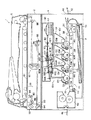
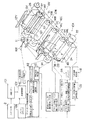
図1は、この発明の画像形成装置として、転写型のカラーデジタル複写装置1(以下、単に複写装置1と称する)の断面を示し、図2は、複写装置1の要部の概略構成、およびその制御系を示す。
【0025】
図1に示すように、複写装置1は、読取手段としてのスキャナ部2と、画像形成手段としてのプリンタ部4と、を備えている。また、スキャナ部2の上部には、原稿自動給送装置6(以下、単にADF6と称する)がセットされている。ADF6は、スキャナ部2の後述する原稿台に対して開閉可能に取付けられ、読取対象物すなわち原稿Dを、原稿台に向けて1枚ずつ給送するとともに、原稿台に載置された原稿Dを原稿台に密着させる原稿押さえとして機能する。
【0026】
プリンタ部4は、周知の減色混合法に基づいて、各色成分毎に色分解された画像、即ち、イエロー (黄、以下、Yと示す) 、マゼンタ (赤の一種、以下、Mと示す) 、シアン (青みがかった紫、以下、Cと示す) およびブラック (黒、以下、Kと示す) の4色の画像をそれぞれ形成する第1乃至第4の画像形成部10Y、10M、10C、10Kを有している。
【0027】
各画像形成部10Y、10M、10C、10Kの下方には、各画像形成部により形成された各色毎の画像を図中矢印a方向に搬送する搬送ベルト21を含む搬送手段としての搬送機構20が配設されている。搬送ベルト21は、図2に示すように、ベルトモータ22により矢印方向に回転される駆動ローラ24と駆動ローラ24から所定距離離間された従動ローラ26との間に巻回されて張設され、矢印a方向に一定速度で無端走行される。尚、各画像形成部10Y、10M、10C、10Kは、搬送ベルト21の搬送方向に沿って直列に配置されている。
【0028】
各画像形成部10Y、10M、10C、10Kは、それぞれ、搬送ベルト21と接する位置で外周面が同一の方向に回転可能に形成された像担持体としての感光体ドラム11Y、11M、11C、11Kを含んでいる。各感光体ドラムには、各感光体ドラムを所定の周速度で回転させるためのドラムモータ9Y、9M、9C、9Kが接続されている。
【0029】
それぞれの感光体ドラム11Y、11M、11C、11Kの軸線は、搬送ベルト21により画像が搬送される方向と直交するよう配置され、各感光体ドラムの軸線が互いに等間隔に配置される。尚、以下の説明においては、各感光体ドラムの軸線方向を主走査方向(第2の方向)とし、感光体ドラムが回転される方向すなわち搬送ベルト21の回転方向(図中矢印a方向)を副走査方向(第1の方向)とする。
【0030】
各感光体ドラム11Y、11M、11C、11Kの周囲には、主走査方向に延出された帯電手段としての帯電ローラ12Y、12M、12C、12K、主走査方向に同様に延出された現像手段としての現像装置13Y、13M、13C、13K、主走査方向に同様に延出された転写手段としての転写装置14Y、14M、14C、14K、および、主走査方向に同様に延出されたクリーニング装置15Y、15M、15C、15Kが、それぞれ、対応する感光体ドラムの回転方向に沿って順に配置されている。尚、各転写装置は、対応する感光体ドラムとの間で搬送ベルト21を狭持する位置、即ち搬送ベルト21の内側に配設されている。また、後述する露光装置による露光ポイントは、それぞれ帯電ローラと現像装置との間の感光体ドラムの外周面上に形成される。
【0031】
搬送機構20の下方には、各画像形成部10Y、10M、10C、10Kにより形成された画像を転写する被画像形成媒体としての記録紙Pを複数枚収容した用紙カセット30が配置されている。
【0032】
用紙カセット30の一端部であって、従動ローラ26に近接する側には、用紙カセット30に収容されている記録紙Pを (最上部から) 1枚ずつ取り出すピックアップローラ32が配置されている。ピックアップローラ32と従動ローラ26との間には、用紙カセット30から取り出された記録紙Pの先端と画像形成部10Yの感光体ドラム11Yに形成されたYトナー像の先端とを整合させるためのレジストローラ34が配置されている。尚、他の感光体ドラム11Y、11M、11Cに形成されたトナー像(M、C、K)は、搬送ベルト21上を搬送される記録紙Pの搬送タイミングに合せて各転写位置に供給される。
【0033】
レジストローラ34と第1の画像形成部10Yとの間であって、従動ローラ26の近傍、実質的に、搬送ベルト21を挟んで従動ローラ26の外周上には、レジストローラ34を介して所定のタイミングで搬送される記録紙Pに、所定の静電吸着力を提供する吸着ローラ36が配置されている。なお、吸着ローラ36の軸線と従動ローラ26の軸線は、互いに平行に配置される。
【0034】
搬送ベルト21の一端であって、駆動ローラ24の近傍、実質的に、搬送ベルト21を挟んで駆動ローラ24の外周上には、搬送ベルト21上に形成された画像の位置を検知するためのセンサ38(後述する)が、駆動ローラ24から所定距離離間して配置されている。センサ38は、透過型或いは反射型の光センサにより構成される。
【0035】
駆動ローラ24の外周上であってセンサ38の下流側の搬送ベルト21上には、搬送ベルト21上に付着したトナー(後述する検出用パターン109を含む)あるいは記録紙Pの紙かすなどを除去するベルトクリーナ40が配置されている。
【0036】
搬送ベルト21を介して搬送された記録紙Pが駆動ローラ24から離脱されてさらに搬送される方向には、記録紙Pを所定温度に加熱することにより記録紙Pに転写されたトナー像を溶融し、トナー像を記録紙Pに定着させる定着装置50が配置されている。
【0037】
プリンタ部4の筐体の右側側面には、記録紙Pを手差し供給するための供給口4aが形成され、供給口4aには給紙トレー42が設けられている。供給口4aを介して給紙された記録紙Pは、レジストローラ34に導かれ、各画像形成部に供給される。また、プリンタ部4の左側側面には、定着装置50を介して排出された記録紙Pを受ける排紙トレー44が設けられている。
【0038】
各感光体ドラムの外周面上にそれぞれ色分解された静電潜像を形成する露光装置60は、後述する画像処理部にて色分解された各色毎の画像データ(Y、M、C、K)に基づいて発光制御される各色毎のレーザー発光装置(図2に黒用のレーザー発光装置104のみ例示してある)を有している。各レーザー発光装置の光路上には、各レーザービームを反射、走査するポリゴンミラー61、およびポリゴンミラー61を介して反射されたレーザービームの焦点を補正して結像させるための第1乃至第3のfθレンズ62、63、64が順に設けられている。
【0039】
第3のfθレンズ64と各感光体ドラム11Y、11M、11C、11Kとの間には、第3のfθレンズ64を通過された各色毎のレーザービームを各感光体ドラムの露光位置に向けて折り曲げる第1の折り返しミラー65(Y、M、C、K)、および、第1の折り返しミラー65Y、65M、65Cにより折り曲げられたレーザービームを更に折り曲げる第2および第3の折り返しミラー66(Y、M、C)、67(Y、M、C)が配置されている。尚、黒用のレーザービームは、第1の折り返しミラー65Kにより折り返された後、他のミラーを経由せずに感光体ドラム11Kに案内される。
【0040】
原稿の画像を読取るスキャナ部2は、その上部に、閉じた状態にあるADF6に対向され、原稿Dがセットされる透明なガラスからなる原稿台81を有している。原稿台81の下方には、原稿台81に載置された原稿Dを照明する露光ランプ82、露光ランプ82からの光を原稿Dに集光させるためのリフレクター84、および原稿Dからの反射光を図中左方向に折曲げる第1ミラー86などが配設されている。尚、これらの露光ランプ82、リフレクター84、および第1ミラー86は、第1キャリッジ88に固設されている。第1キャリッジ88は、図示しない歯付きベルト等を介して図示しないパルスモータに接続され、パルスモータの駆動力が伝達されて原稿台81に沿って平行に移動されるようになっている。
【0041】
第1キャリッジ88に対して図中左側、すなわち第1ミラー86により反射された反射光が案内される方向には、図示しない駆動機構たとえば歯付きベルトならびにDCモータなどを介して原稿台81と平行に移動可能に設けられた第2キャリッジ90が配設されている。第2キャリッジ90には、第1ミラー86により案内される原稿Dからの反射光を下方に折曲げる第2ミラー92、および第2ミラー92からの反射光を図中右方に折り曲げる第3ミラー94が互いに直角に配置されている。第2キャリッジ90は、第1キャリッジ88に従動されるとともに、第1キャリッジ88に対して1/2の速度で原稿台81に沿って平行に移動されるようになっている。
【0042】
第2キャリッジ90を介して折返された光の光軸を含む面内には、第2キャリッジ90からの反射光を所定の倍率で結像させる結像レンズ96が配置され、結像レンズ96を通過した光の光軸と略直交する面内には、結像レンズ96により集束性が与えられた反射光を電気信号すなわち画像データに変換するCCDイメージセンサ98が配置されている。
【0043】
しかして、露光ランプ82からの光をリフレクター84により原稿台81上の原稿Dに集光させると、原稿Dからの反射光が、第1ミラー86、第2ミラー92、第3ミラー94、および結像レンズ96を介してCCDイメージセンサ98に入射され、ここで画像データに変換される。
【0044】
次に、上記のように構成された複写装置1の動作について詳細に説明する。
【0045】
図示しない電源スイッチが投入されることで、複写装置1がイニシャライズされ、定着装置50が所定温度に加熱されるとともに各モータの回転速度が安定化され、待機状態に維持される。そして、スキャナ部2により原稿Dが走査され、CCDイメージセンサ98を介して原稿Dの画像が読取られる。読取られた画像データは、画像メモリ101に一旦記憶され、画像処理部102にて各色毎の画像データ(Y、M、C、K)に色分解され、必要に応じて、各色毎に変倍、回転、移動等の画像処理がなされる。
【0046】
ここで、第1の画像形成部10Yを用いて、Y (イエロー) 画像を形成する工程について説明する。尚、言うまでもなく、第2ないし第4の画像形成部10M、10C、10KによりM (マゼンタ) 画像、C (シアン) 画像およびK (ブラック) 画像も同様に形成される。
【0047】
まず、感光体ドラム11Yの表面が帯電ローラ12Yによって一様に帯電される。続いて、画像処理部102にて処理されたY(イエロー)画像データに基づいてレーザー発光装置104が発光制御され、露光装置60を介してY画像データに基づくレーザー光が感光体ドラム11Yの所定の露光位置に照射される。これにより、Y画像データに対応するY静電潜像が感光体ドラム11Y上に形成される。
【0048】
感光体ドラム11Yに形成されたY静電潜像は、Yトナーを収容した現像装置13Yにより現像されて可視像化され、感光体ドラム11Y上でYトナー像に変換される。
【0049】
感光体ドラム11Y上のYトナー像は、感光体ドラム11Yと搬送ベルト21が対向する転写位置で、用紙カセット30から取り出され、レジストローラ34により搬送ベルト21上に所定のタイミングで吸着および整位された記録紙Pに転写装置14Yによって転写される。
【0050】
以下、第2の画像形成部10M、第3の画像形成部10Cおよび第4の画像形成部10Kのそれぞれにより、各感光体ドラム11M、11Cおよび11Kに形成されたMトナー像、Cトナー像およびKトナー像が、搬送ベルト21により搬送されている記録紙P上に、順に、重ね合わせられる。即ち、複数色の印字の場合、各画像形成部10Y、10M、10Cおよび10Kにより、帯電→露光→現像→転写を1周期とする工程の画像形成動作が実行され、記録紙Pに複数色のトナー像が多重転写される。
【0051】
この場合、各感光体ドラム11Y、11M、11C、11Kが記録紙Pの搬送方向に沿って所定距離離間して配置されていることから、搬送ベルト21上を搬送される記録紙P上に各色の画像を重ね合せるため、各色毎のレーザー発光装置による露光タイミングをずらしている。
【0052】
感光体ドラム11Y、11M、11Cおよび11K上に転写されずに残った残留トナーは、クリーニング装置15Y、15M、15Cおよび15Kによって、それぞれ清掃される。
【0053】
各色のトナー像が転写された記録紙Pは、搬送ベルト21から剥離されて定着装置50に搬送され、定着装置50によって加熱されたトナー像が記録紙P上に溶融定着されたのち、排紙トレイ44に排出される。
【0054】
また、搬送ベルト21に付着した各トナーおよび記録紙Pから生じる紙かすなどは、ベルトクリーナ40により取り除かれる。
【0055】
次に、図2を参照して、各感光体ドラム11Y、11M、11C、11Kの周速度と搬送ベルト21の走行速度とを一致させる制御について説明する。尚、ここでは、黒用の感光体ドラム11Kの周速度と搬送ベルト21の走行速度とを一致させる場合を例にとって説明するが、他の感光体ドラム11Y、11M、11Cの周速度も同様に制御される。
【0056】
まず、ドラムモータ9Kおよびベルトモータ22が、それぞれのモータドライバ112および114の制御により矢印方向に回転を開始される。この場合、各モータドライバ112、114は、感光体ドラム11Kの周速度と搬送ベルト21の走行速度とが一致するように予め設定された基準の回転速度となるように、ドラムモータ9Kおよびベルトモータ22を回転する。
【0057】
つまり、各モータの回転が開始されると、ドラムモータ9Kの回転速度が回転速度検出器116によって検出され、この回転速度が予め設定した基準値と比較される。そして、ドラムモータ9Kの実際の回転速度と基準値との間の誤差が算出され、この誤差が増幅されて制御信号としてモータドライバ112に出力される。モータドライバ112は、この制御信号に従ってドラムモータ9Kの回転速度を制御し、ドラムモータ9Kの回転速度を基準値と一致させる。
【0058】
一方、ベルトモータ22の回転速度が回転速度検出器118によって検出され、この回転速度がモータ回転目標値設定回路120(以下、単に設定回路120と称する)に入力される。設定回路120は、ベルトモータ22の実際の回転速度を基準値と比較し、その誤差を算出する。そして、算出された誤差が増幅器によって増幅され、制御信号としてモータドライバ114に出力される。モータドライバ114は、この制御信号に従ってベルトモータ22の回転速度を制御し、ベルトモータ22の回転速度を基準値と一致させる。これにより、感光体ドラム11Kの周速度が搬送ベルト21の走行速度と一致される。
【0059】
更に、上記のように感光体ドラム11Kの周速度と搬送ベルト21の走行速度とが制御された状態で、画像処理部102により、クロックカウンタ106から出力されるクロック信号に基づく所定の時間間隔を有する時定数が形成され、画像メモリ101に予め記憶した速度制御用パターンが読み出される。そして、時定数に基づく速度制御用パターンが画像処理部102にて用意される。尚、ここでは、上記速度制御用パターンは、感光体ドラム11K或いは搬送ベルト21上に出力された際に、副走査方向に所定間隔離間して並んだ主走査方向に延びた所定長さの複数の線分から成る。
【0060】
そして、感光体ドラム11K上の所定の露光位置に、上記速度制御用パターンに応じたレーザービームが露光装置60を介して照射され、感光体ドラム11Kの表面に速度制御用パターンの静電潜像108が形成される。尚、静電潜像108が形成される位置は、この静電潜像が現像されて搬送ベルト21上に転写された際に、搬送ベルト21上の記録紙Pが搬送される領域以外、即ち記録紙Pの幅方向外側の余白部分、或いは図3に示すように続けて搬送される記録紙Pの間の余白部分に検出用のパターンを形成するように、設定されている。
【0061】
感光体ドラム11K上に形成された静電潜像108は、現像装置13Kを介して現像された後、転写装置14Kにより順次搬送ベルト21上に転写され、搬送ベルト21上に検出用パターン109が形成される。検出用パターン109は、搬送ベルト21の走行に応じて順次搬送され、ベルトクリーナ40によって順次消去される。尚、検出用パターン109は、ベルトクリーナ40の手前でセンサ38によって検知され、所定のピッチを有するタック信号として電気信号に変換されて抽出される。つまり、検出用パターン109は、センサ38により検出される度に消去されて書換えられる。
【0062】
このようにセンサ38によって検知されたタック信号は、画像処理部102にて形成された時定数と比較され、両者の間の誤差がベルト速度の誤差として設定回路120に出力される。設定回路120では、この速度誤差に基づいて、予め設定したベルトモータ22の回転速度の基準値を補正し、回転速度の目標値を改めて設定し直す。そして、ベルトモータ22が、補正された基準値に基づいて回転制御される。
【0063】
以上のように、搬送ベルト21上に実際に形成される画像のパターンを検出し、このパターンのズレに基づいて搬送ベルト21を走行させるベルトモータ22の回転速度の基準値を補正することにより、搬送ベルト21の延びや駆動ローラ24の径変化等に起因した搬送ベルト21の走行速度の変化をその都度補正でき、速度変化による画像位置の副走査方向のズレを防止できる。
【0064】
ところで、搬送ベルト21の延びや駆動ローラ24の径変化の原因としては、駆動ローラ24に近接して配置された定着装置50からの熱による熱膨張などであるが、いずれにしても搬送ベルト21の経時的な速度変化は比較的緩やかなものである。従って、搬送ベルト21上に形成する検出用パターン109は、図2のように連続したものでなくても良く、図3のように所定のインターバルを置いた検出用パターン109´とすることもできる。
【0065】
また、検出用パターン109(109´)を検知するセンサ38は、搬送ベルト21のシーム21aを検出するためのセンサと兼用することができる。つまり、シーム検出用のマーク122の副走査方向の幅を比較的大きくし、検出用パターン109の副走査方向の幅と差を持たせ、検出した信号にフィルターをかけてマーク122と検出用パターン109とを区別することにより、両者を別々のものとして検出できる。従って、1つのセンサ38で搬送ベルト21のシーム21aと検出用パターン109とを検出できる。
【0066】
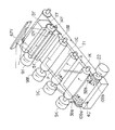
次に、複写装置1の複数の画像形成部10Y、10M、10C、10Kにより形成されるカラー画像の色ずれを検出して補正する方法について図4乃至図7を用いて詳細に説明する。
【0067】
まず、各感光体ドラム11Y、11M、11C、11K、および搬送ベルト21の回転が安定した状態で、画像処理部102(補正手段)において、クロックカウンタ106から出力される基準クロック信号に基づいて所定の時間間隔を有する時定数が形成される。そして、画像処理部102によって、画像メモリ101(記憶手段)に予め記憶された後述する色ずれ検出用パターン(以下、単にパターンと称する)の画像データが読み出され、各感光体ドラム上に時定数に応じた各色毎のパターンの静電潜像が形成される。
【0068】
各感光体ドラムに形成されたパターンの静電潜像は、それぞれの色トナーにより現像され、各色のパターンのトナー像が搬送ベルト21上に順次転写される。この際、各色のパターン(K、Y、M、C)が、図4に示すように、搬送ベルト21上で副走査方向に沿って隣接した状態で所定間隔づつ離間されて転写されるように、各色のパターンの形成タイミングがずらされる。尚、各色パターンは、搬送ベルト21の主走査方向に所定距離離間して複写装置1のリア側とフロント側にそれぞれ1つづつ、即ち記録紙Pが搬送される領域より外側の搬送ベルト21の両端部近くにそれぞれ形成される。
【0069】
また、このように主走査方向に離間して形成される複数組のパターンを検出するため、検出手段としての一対のセンサ38a、38bが主走査方向に離間してそれぞれのパターン109a、109b上に配設されている。尚、各センサ38a、38bは、主走査方向に沿って互いに平行に固設されてる。
【0070】
ここで、転写ベルト21上に形成されるこの発明の第1の実施の形態に係るパターンについて図5を参照して説明する。尚、ここでは、搬送ベルト21の主走査方向に離間して形成されたパターン109a、109bを、説明の便宜上、近接して図示した。また、図5に示すような4組の色パターン(Y、M、C、K)は、時定数に応じたピッチでそれぞれ図7(a)に示すように搬送ベルト21上に複数回形成され、例えば、連続して搬送される記録紙Pの間に形成される。
【0071】
各パターンは、主走査方向に延びた長さの異なる複数本の線分を有し、各線分は互いに平行且つ等間隔で形成される。複写装置1のリア側の搬送ベルト21上に形成されるパターン109aは、各線分のリア側の端部、即ち搬送ベルト21の端に近接した端部が副走査方向に沿って揃えられ、搬送方向下流側(図中左側)の線分から順に所定長さづつ短くなるように形成されている。つまり、各線分のフロント側の端部、即ち搬送ベルト21の端から離間した端部がセンサ38aによるパターン検出方向(副走査方向)を斜めに横切る方向に並んで配置されている。尚、複写装置1のフロント側の搬送ベルト21上に形成されるパターン109bは、上記パターン109aと上下方向に対称形に形成される。
【0072】
以下、上記パターン109a、109bを用いて、搬送ベルト21上に形成されるカラー画像の色ずれを補正する方法について、図6に示すフローチャートを参照して説明する。
【0073】
まず、画像処理部102によって、印画すべき画像データとともに上述したパターン109a、109bの画像データが画像メモリ101から読み出される。そして、画像処理部102によって、印画すべき画像データが各色毎の画像データ(Y、M、C、K)に色分解され、各色毎の画像データが必要に応じて変形され、各画像データにそれぞれのパターンデータが合成される。
【0074】
この場合、画像処理部102において、基準クロックに基づく時定数が形成され、この時定数に応じたパターンデータが各色毎の画像データに合成されるが、各色用のパターンデータは対応する色の画像データに対してそれぞれ所定タイミングだけずらされて合成される。つまり、各色毎の画像データに応じて形成される4色のトナー像が、搬送ベルト21上を搬送される記録紙P上で正確に重ね合わされるとともに、各色の画像データに合成される各色用のパターンデータに応じた4色のトナー像が搬送ベルト21上で図5に示すように所定間隔づつずらされて形成されるように、各色毎の画像データとパターンデータとが合成される。
【0075】
従って、各色毎の画像データに応じたトナー像を記録紙P上で正確に重ね合わせるためには、各色用のパターンデータに応じたトナー像、即ち各色パターンの相対的な位置ずれを補正するように、各画像形成部10Y、10M、10C、10Kによる画像形成位置を補正すれば良いことになる。尚、各色パターンの相対的な位置ずれは、一対のセンサ38a、38bのみを用いて検出され、(a)副走査方向、(b)主走査方向、(c)主走査方向倍率、および(d)スキューに対する位置ずれが検出できる。従って、画像処理部102による画像データおよび色パターンの合成時には、各色毎に最適な上記(a)〜(d)のパターン位置(即ち、画像位置)が考慮される。
【0076】
各色パターンの位置が設定されると、各色毎の画像データおよびパターンデータに基づいて、各色毎のレーザー発光装置を介して各色毎のレーザービームが射出され、各色の感光体ドラム11Y、11M、11C、11Kがそれぞれ露光される。これにより、各感光体ドラム上に各色毎の画像データに応じた静電潜像がそれぞれ形成されるとともに、各色の画像位置を検出するための上述した色パターンに応じた静電潜像が形成される。
【0077】
各感光体ドラム上に形成された静電潜像は、それぞれの現像装置13Y、13M、13C、13Kによって現像され、各色のトナー像に変換される。各色のトナー像は、それぞれの転写位置において記録紙Pおよび搬送ベルト21上に順次転写される。つまり、印画すべき画像のトナー像が記録紙P上に重ね合わされて転写され、各色パターンのトナー像が記録紙Pから外れた搬送ベルト21上に副走査方向に沿って近接した状態で互いに離間されて転写される。
【0078】
各色のトナー像が重ね合わされて転写された記録紙Pは、搬送ベルト21から離脱された後、定着装置50を通過され、ここで、トナーが加熱されて溶融され、記録紙Pに定着される。そして、このようにカラー画像が形成された記録紙Pは、排紙トレー44上に排紙される。
【0079】
一方、搬送ベルト21上に転写された各色パターン109a、109bは、搬送ベルト21の走行に従って移動され、それぞれ対向する位置に設けられたセンサ38a、38bによって検出される。センサ38a、38bによって検出された各色パターンは、ベルトクリーナ40によってその都度消去され、新しく書換えられる。
【0080】
各センサ38a、38bにより検出された色パターン109a、109bは、以下のようにタック信号化されて処理される。
例えば、複写装置1のリア側のパターン109aの各色パターンの第1の線分(最も長い線分)の通過タイミングをセンサ38aによって検出し、黒パターンの第1の線分から他の色の第1の線分までのピッチDc、Dm、Dyをそれぞれ算出する。そして、これらのピッチDc、Dm、Dyを画像合成時の設定値と比較し、各色パターンの第1の線分が等間隔となるように、各色パターンの副走査方向位置(a)を補正する。
【0081】
また、リア側のパターン109aの各色パターンのセンサ38aによる線分検出本数Rk、Rc、Rm、Ryをカウントし、黒パターンの線分検出本数Rkに対する他の色パターンの線分検出本数Rc、Rm、Ryを比較する。そして、他の色パターンの線分検出本数Rc、Rm、Ryが黒パターンの線分検出本数Rkと一致するように、各色パターンの主走査方向位置(b)を補正する。
【0082】
つまり、各色パターンの線分検出本数は、色パターンが搬送ベルト21の端から離れる方向にずれて形成されるにつれて多くなり、搬送ベルト21の端に近付く方向にずれるにつれて少なくなる。従って、各色パターンの線分検出本数を一致させることにより各色パターンの主走査方向位置(b)を一致させることができる。
【0083】
また、上記のようにリア側の各色パターンの線分検出本数Rk、Rc、Rm、Ryをカウントするとともに、フロント側の各色パターンの線分検出本数Fk、Fc、Fm、Fyをカウントし、各色毎の検出本数の差Fk−Rk、Fc−Rc、Fm−Rm、Fy−Ryをそれぞれ算出する。次に、各色毎の検出本数の差から、各色パターン間の主走査方向長さを演算し、黒パターン間の主走査方向長さに対する他の色パターン間の主走査方向長さを比較する。そして、他の色パターン間の主走査方向長さが黒パターン間の主走査方向長さと一致するように、各色パターンの主走査方向倍率(c)を補正する。
【0084】
更に、リア側の各色パターンの第1の線分の通過タイミングを検出するとともに、フロント側の各色パターンの第1の線分の通過タイミングを検出し、各色毎の検出タイミングのずれ量、即ちスキュー量Sk、Sc、Sm、Syを算出する。そして、黒パターンのスキュー量Skに対する他の色パターンのスキュー量Sc、Sm、Syを比較し、各色パターンのスキュー量が黒パターンのスキュー量と一致するように、各色パターンのスキューを補正する。
【0085】
以上のように、搬送ベルト21上に形成した各色パターンの相対的な位置ズレを(a)〜(d)に関して補正することにより、記録紙P上で重ね合わされる画像の色ズレをなくすことができる。
【0086】
特に、本実施の形態のパターンを用いて画像の位置ズレを補正することにより、従来のクサビ形のパターンを用いた場合と比較して、主走査方向の位置ズレを高精度に補正できる。つまり、本実施の形態では、副走査方向に移動する各色パターンの線分本数をそれぞれカウントし、基準となる色パターン(例えば、黒パターン)の線分本数と他の色パターンの線分本数とを比較し、各色パターンの線分本数が一致するように各色パターンの主走査方向の位置ズレを補正している。このため、各色パターンの主走査方向の位置ズレをデジタル的にとらえることができ、主走査方向の位置ズレをより高精度に補正できる。
【0087】
従って、本実施の形態によると、各色画像を正確に重ね合せることができ、記録紙上に形成される画像の色ズレを確実に防止でき、良質な画像を形成できる。
【0088】
また、本実施の形態によると、光センサ38を用いて色パターンを検出するため、従来のようにCCDセンサなどの高価な装置を必要とせず、装置を比較的安価に製造できる。
【0089】
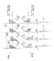
次に、この発明の第2の実施の形態に係るパターンおよび第3の実施の形態に係るパターンについて、図7(b)および図7(c)を用いて説明する。尚、これらのパターンは、上述した第1の実施の形態に係る色パターン(図7a)と同様の方法およびタイミングで形成される。
【0090】
図7(b)に示すように、第2の実施の形態に係るパターン130a、130bは、副走査方向に並べられた4組の色パターンにより形成され、各色パターンは第1の実施の形態のパターン109a、109bと同様に時定数に応じて形成される主走査方向に延びた第1の線分をそれぞれ有している。また、各色パターンは、第1の線分から斜めに延びた複数本の第2の線分を有している。これらの第2の線分は、互いに平行且つ等間隔で形成され、第1の線分から搬送ベルト21の端に向けて傾斜(例えば、45度の傾斜角度で)され、第1の線分から離間した端部が副走査方向に沿って揃えられている。尚、各色パターンは、第1の実施の形態と同様に、搬送ベルト21の両端近傍にそれぞれ形成され、互いに対称形に形成されている。
【0091】
上記のように形成された色パターンは、センサ38a、38bにより検出され、各色パターンの第1の線分の検出タイミングが設定値と比較され、各色パターンの副走査方向の位置ズレおよびスキューが補正される。また、各色パターンの第2の線分の検出本数がカウントされ、各色パターン間の検出本数が一致するように、各色パターンの主走査方向の位置ズレおよび主走査方向倍率が補正される。このように、本実施の形態のパターンを用いても第1の実施の形態と同様に画像の色ズレを確実に防止でき良質な画像を形成できる。
【0092】
図7(c)に示すように、第3の実施の形態に係るパターン140a、140bは、副走査方向に並べられた4組の色パターンにより形成され、各色パターンは主走査方向に互いに平行且つ等間隔で延びて形成された同じ長さの複数本の線分を有している。また、各色パターンは、各線分の間に1つづつ設けられた複数のドットを有し、これらのドットは、搬送方向下流側のものから順に搬送ベルト21の端から離間する方向にずれて形成されている。つまり、複数のドットは、副走査方向を斜めに横切る方向に並んで形成されている。尚、各色パターンは、搬送ベルト21の両端近傍にそれぞれ形成され、互いに対称形に形成されている。
【0093】
上記色パターンがセンサ38a、38bにより検出されると、各色パターンの搬送方向最下端の線分の検出タイミングが設定値と比較され、各色パターンの副走査方向の位置ズレおよびスキューが補正される。また、各色パターンのドットが検出されるまでの線分検出本数がカウントされ、この検出本数が各色パターン間で一致するように、各色パターンの主走査方向の位置ズレおよび主走査方向倍率が補正される。つまり、ドットが検出されるまでの線分通過本数が多いほど色パターンが搬送ベルト21の端に近く、線分検出本数が少ないほど色パターンが搬送ベルト21の端から遠いことを判断でき、本数を比較することにより主走査方向の位置ズレを検出できる。このように、本実施の形態のパターンを用いても上述した第1および第2の実施の形態と同様に画像の色ズレを確実に防止でき良質な画像を形成できる。
【0094】
次に、搬送ベルト21の位置ズレを補正する方法について図8および図9を参照して説明する。
搬送ベルト21は、ベルトモータ22により回転される駆動ローラ24と駆動ローラ24から所定距離離間された従動ローラ26との間に巻回されて張設されている。このため、複写装置1の保守点検や部品交換のとき、または複写装置1の移設時に、装置に衝撃が与えられると、搬送ベルト21が正規の搬送位置からズレる場合がある。つまり、このような衝撃により、搬送ベルト21が各ローラ24、26の軸方向にズレる。このように、搬送ベルト21が正規の位置からズレると、搬送ベルト21上で重ね合わされる画像に色ズレを生じ、画像が劣化される。
【0095】
このため、搬送ベルト21を巻回した従動ローラ26を複写装置1のフロント側に向けて緩やかに集束させたテーパーローラ26´とし、駆動ローラ24のフロント側の端部に搬送ベルト21の移動を規制するための規制板151を設け、駆動ローラ24のリア側の端部に搬送ベルト21の抜けを防止するための補助規制板152を設けた装置が知られている。
【0096】
この構成により、搬送ベルト21が正規の位置からズレた場合であっても、複写装置1の電源投入時におけるウォームアップ動作、即ち定着装置50の加熱温度安定化や各モータの速度の安定化動作中の搬送ベルト21の走行に伴い搬送ベルト21が正規の位置に復帰される。
【0097】
しかしながら、上記のような構成により搬送ベルト21を正規の位置に復帰させる場合、搬送ベルト21が正規の位置に戻るまでに比較的長い時間を必要とし、搬送ベルト21が戻るまでの間に形成された画像に色ズレ等の画像不良を生じる。
【0098】
この間の色ズレをなくすため、搬送ベルト21の復帰動作を高速にすべくテーパーローラ26´の傾斜をきつくすることが考えられるが、傾斜をきつくすると、搬送ベルト21を瞬時に正規の位置に戻すことができる反面、搬送ベルト21の疲労座屈やベルト端面の疲労摩耗等の新たな問題が生じる。
【0099】
よって、本発明においては、テーパーローラ26´の傾斜をきつくすることなく搬送ベルトを瞬時に正規の位置へ移動させるための強制機構(強制手段)を設けた。
【0100】
この発明の第1の実施の形態に係る強制機構160は、搬送ベルト21の下方に配置され、搬送ベルト21に近接して主走査方向(搬送ベルト21の走行方向を横切る方向)に延びたスライダ161、このスライダ161を主走査方向に沿ってスライド可能に保持したフレーム162、スライダ161を主走査方向に沿って矢印a方向(複写装置1のフロント方向)に移動させるソレノイド163、およびスライダ161を矢印b方向(複写装置1のリア方向)に付勢するバネ164を備えている。
【0101】
スライダ161は、スライダ161がバネ164の付勢力によりその初期位置に配置された状態で、搬送ベルト21のリア側の端部から僅かに離間した位置に配置される強制面161aを有している。強制面161aは、ソレノイド163によりスライダ161が矢印a方向に移動された際に、搬送ベルト21のリア側の端部を矢印a方向に押し、搬送ベルト21を装置のフロント側の正規の位置へ移動させる強制力を生じる。
【0102】
図9には、上記強制機構160の動作を制御する制御系のブロック図を示してある。強制機構160の制御系は、制御手段としての制御部170を有している。制御部170には、複写装置1の電源スイッチ171、および搬送ベルト21のズレを検知するベルトズレ検知センサ172(検知手段)が接続されている。検知センサ172は、図8に示すように、搬送ベルト21のフロント側の端部近傍に設けられ、搬送ベルト21がある許容範囲を超えて装置のリア方向に移動された際にオンされ、搬送ベルト21が正規の位置に復帰された際にオフされるようになっている。また、制御部170には、ソレノイド163を作動させるためのコントローラ174が接続されている。
【0103】
強制機構160による強制力を生じさせるタイミングとしては、複写装置1の電源スイッチ171が投入されたとき、或いは搬送ベルト21が許容範囲を超えたズレを生じたときなどが考えられる。そして、装置の電源スイッチ171が投入され、或いは検知センサ172により搬送ベルト21のズレが検知されると、制御部170の制御により、コントローラ174が付勢されてソレノイド163がオンされる。
【0104】
すると、スライダ161がフレーム162に沿って矢印a方向に移動され、強制面161aにより搬送ベルト21のリア側の端部が装置のフロント側に向けて押される。これにより、搬送ベルト21が正規の位置に強制的に瞬時に移動され、搬送ベルト21が正規の位置に移動されるまでの時間が短縮され、その間の色ズレ等の画像劣化を低減できる。
【0105】
尚、強制機構160による強制力は、ソレノイド163が通電されている間中発生され、検知センサ172により搬送ベルト21の端部が検出されて搬送ベルト21が正規の位置に復帰された時点でソレノイド163の通電が遮断されて強制力が消失される。ソレノイド163による強制力がなくなると、バネ164の復元力によりスライダ162が初期位置に戻され、強制面161aが搬送ベルト21の端部から離間される。
【0106】
また、この発明の第2の実施の形態に係る強制機構180は、テーパーローラ26´の回転軸上に設けられ、テーパーローラ26´の回転軸の両端に設けられた軸受181a、181b、フロント側の軸受181bを保持したスライダ182、このスライダ182を副走査方向に沿ってスライド自在に保持したフレーム183、スライダ182を副走査方向に沿って矢印c方向に移動させるソレノイド184、およびスライダ182を矢印d方向に付勢するバネ185を備えている。
【0107】
上記強制機構180はテーパーローラ26´を以下の方法により揺動させるため、テーパーローラ26´の回転軸を保持した軸受181a、181bは、軸の保持角度を可変する自動調心性のベアリングにより構成されている。
【0108】
本実施の形態に係る強制機構180は、上記第1の実施の形態の強制機構160と同様に、制御部170により制御される。つまり、複写装置1の電源スイッチ171が投入され、或いは検知センサ172により搬送ベルト21のズレが検知されると、ソレノイド184が通電される。
【0109】
ソレノイド184が通電されると、スライダ182が矢印c方向に移動されるとともにフロント側の軸受181bが移動され、テーパーローラ26´の回転軸がリア側の軸受181aを中心に揺動される。すると、テーパーローラ26´による搬送ベルト21の正規位置への復帰力が増大され、搬送ベルト21が正規の位置へ強制的且つ瞬時に移動される。これにより、搬送ベルト21の復帰時間が短縮され、搬送ベルト21が復帰するまでの間に形成される画像の色ズレ等の画像劣化を低減できる。
【0110】
また、上述した第1および第2の実施の形態の強制機構160、180の他に、駆動ローラ24のリア側の端部に搬送ベルト21のズレを補正するための以下のような補助的な機構を設けることにより、各強制機構160、180による強制力を搬送ベルト21に作用させる機会を少なくでき、搬送ベルト21の疲労による寿命を延長できる。
【0111】
つまり、補助機構は、駆動ローラ24のリア側の端部に設けられた補助規制板152の代りに、装置のリア側に向けて広がったテーパー部を有する補助規制部152´を備えている。そして、補助規制部152´は、搬送ベルト21が正規の位置にあるときには、テーパー部の手前に搬送ベルト21の端部が位置し、搬送ベルト21がズレたときには、搬送ベルト21の端部がテーパー部に乗り上げるように、位置決めされて配設されている。
【0112】
従って、搬送ベルト21のリア側の端部が補助規制部152´のテーパー部に乗り上げるような搬送ベルト21のズレを生じた場合には、強制機構160或いは180を作動させることなく、搬送ベルト21の走行に伴って搬送ベルト21が正規の位置に自動的に復帰される。これにより、強制機構160、180を作動させる機会を少なくできる。
【0113】
尚、この発明は、上述した実施の形態に限定されるものではなく、この発明の範囲内で種々変形可能である。例えば、搬送ベルトを正規の位置へ強制的に復帰させる強制機構を作動させるアクチュエータとしてソレノイドの代りにモータを用い、モータによる駆動力をギアとラックにより伝達する構成とすることもできる。また、上述の複数の線分パターン検出による制御と、ベルトを強制的に正規の位置へ戻すための機構を組み合わせて使用してもよいことは、いうまでもない。
【0114】
【発明の効果】
以上説明したように、この発明の画像形成装置は、上記のような構成および作用を有しているので、安価な装置構成により、画像形成位置ズレを確実に補正でき、良質な画像を形成できる。
【図面の簡単な説明】
【図1】この発明の実施の形態に係るデジタルカラー複写装置を示す概略図。
【図2】図1の複写装置の要部の構成およびその制御系を示す斜視図。
【図3】パターンを記録紙の間に形成した状態を示す図。
【図4】この発明の第1の実施の形態に係るパターンが搬送ベルト上に転写された複写装置の要部を示す斜視図。
【図5】図4のパターンの拡大図。
【図6】図4のパターンを用いて画像の色ズレを補正する動作を説明するための図。
【図7】他の実施の形態に係るパターンを示す図。
【図8】搬送ベルトの位置を補正する強制機構を示す概略図。
【図9】図8の強制機構の動作を制御する制御系を示すブロック図。
【図10】従来の色ズレ補正方法を説明するための図。
【符号の説明】
1…複写装置、
9Y、9M、9C、9K…ドラムモータ、
10Y、10M、10C、10K…画像形成部、
11Y、11M、11C、11K…感光体ドラム、
12Y、12M、12C、12K…帯電装置、
13Y、13M、13C、13K…現像装置、
14Y、14M、14C、14K…転写装置、
15Y、15M、15C、15K…クリーニング装置、
20…搬送機構、
21…搬送ベルト、
22…ベルトモータ、
24…駆動ローラ、
26…従動ローラ、
38a、38b…センサ、
40…ベルトクリーナ、
50…定着装置、
60…露光装置、
98…CCDイメージセンサ、
101…画像メモリ、
102…画像処理部、
104…レーザー発光装置、
106…クロックカウンタ、
109…検出用パターン、
112、114…モータドライバ、
120…設定回路
P…記録紙。[0001]
BACKGROUND OF THE INVENTION
The present invention relates to an image forming apparatus that can be used in a color printer apparatus, a color digital copying apparatus, and the like and forms a color image by forming an image for each color component on a plurality of photosensitive drums and superimposing them on a recording sheet.
[0002]
[Prior art]
Conventionally, as disclosed in Japanese Patent Laid-Open No. 6-35287, an apparatus for forming images by sequentially transferring multiple toner images formed on a plurality of photoconductors onto a sheet carried by a conveyor belt. There is.
[0003]
By the way, in this type of transfer type color copying machine, it is known that color misregistration occurs in the image when the toner images for each color component to be superimposed on the recording paper P do not overlap in order. . As a cause of color misregistration, a tilt or a position misalignment inherent in each image forming unit, a deviation in image formation timing of an image formed via each image forming unit, or each image is superimposed on the recording paper P. The transfer position shift at the time is known.
[0004]
For this reason, for example, a CCD sensor or the like is incorporated in the copying apparatus to detect the positional deviation of the image formed by each image forming unit and transferred to the recording paper, and based on the detected positional deviation of the image. There is known a method of correcting color misregistration by correcting the relative position of the exposure apparatus with respect to the body drum or the positions of the image forming units. According to this method, for example, even when the conveyance speed is changed due to thermal expansion of the conveyance belt, the position of the image to be actually transferred is detected and corrected, so that the positional deviation of the image on the recording paper is reliably corrected. it can. However, since a CCD sensor is very expensive, incorporating a CCD sensor in a copying apparatus causes a problem of increasing the price of the copying apparatus. This results in a problem that results in an increase in running cost that is disadvantageous to the user.
[0005]
For this reason, a wedge-shaped
[0006]
According to this method, the deviation of the image in the sub-scanning direction is detected by comparing the time interval at which the first line segment extending in the main scanning direction of each color pattern is detected with the time constant when each color pattern is formed. can do. Further, by comparing the time from detection of the first line segment to detection of the second line segment extending obliquely from the first line segment for each color pattern, main scanning of each color image is performed. Directional deviation can be detected. That is, in FIG. 10, when the time from detection of the first line segment of each color pattern to detection of the second line segment is relatively long, the direction of the color pattern toward the center of the
[0007]
According to the above method, it is possible to detect the positional deviation in the sub-scanning direction of the image and to detect the positional deviation in the main scanning direction without using an expensive device such as a CCD, and to correct the positional deviation of each color image. Can be prevented.
[0008]
[Problems to be solved by the invention]
However, when detecting a positional deviation of an image using a wedge-shaped pattern as described above, the positional deviation of an image in the sub-scanning direction can be corrected with relatively high accuracy, but the positional deviation of the image in the main scanning direction is increased. It cannot be corrected to accuracy. That is, the positional deviation in the main scanning direction of the wedge-shaped pattern is determined by comparing the time from the detection of the first line segment to the detection of the second line segment. There is a problem that an error is likely to occur in the detection value due to the detection accuracy of the sensor.
[0009]
As described above, if the positional deviation of the image cannot be corrected accurately, the respective color images cannot be accurately superimposed, resulting in a problem of color deviation and deterioration of the image.
[0010]
The present invention has been made in view of the above points, and an object of the present invention is to provide an image forming apparatus capable of reliably correcting a shift in image forming position and forming a high-quality image with an inexpensive apparatus configuration. .
[0012]
[Means for Solving the Problems]
To achieve the above purpose This departure Mysterious In the image forming apparatus that outputs a plurality of images in a superimposed manner, the image forming apparatus holds a plurality of images and conveys them in a first direction, and a second direction orthogonal to the first direction Extending in parallel with each other and having one end aligned at equal intervals along the first direction, and along the first direction. In the second direction Storage means storing pattern data for outputting a pattern having a plurality of line segments formed so as to be shortened by a predetermined length on the conveying means, and outputting a first image on the conveying means And a first image forming unit that outputs a first pattern as a pattern indicating an output position of the first image on the conveying unit based on the pattern data stored in the storage unit; A second image is output by being superimposed on the first image, and a second pattern as a pattern indicating the output position of the second image is output based on the pattern data stored in the storage means. A second image forming unit that outputs adjacent to the first pattern along the first direction, and the first and second units that are provided facing the conveying unit and are conveyed in the first direction. 2 The first and second images are compared so that the number of line segments of the first and second patterns detected by the detection means and the detection means for sequentially detecting the patterns are compared. Correction means for correcting the output positions of the first and second images output by the forming means along the second direction.
[0013]
This departure Mysterious In the image forming apparatus that outputs a plurality of images in a superimposed manner, the image forming apparatus holds a plurality of images and conveys them in a first direction, and a second direction orthogonal to the first direction And a pattern having a plurality of second line segments extending in parallel to each other at equal intervals in a direction inclined from the first line segment with respect to the first direction. A storage unit that stores pattern data to be output on the transport unit, a first image is output on the transport unit, and the first data is stored on the basis of the pattern data stored in the storage unit. A first image forming unit that outputs a first pattern as a pattern indicating an output position of the image on the conveying unit; a second image that is superimposed on the first image; and a storage unit that outputs the second image Stored in Second image forming means for outputting a second pattern as a pattern indicating the output position of the second image on the basis of the image data adjacent to the first pattern along the first direction; A detecting means provided opposite to the conveying means and sequentially detecting the first and second patterns conveyed in the first direction, and the first and second detected by the detecting means. The number of line segments in the pattern is compared, and the output positions of the first and second images output by the first and second image forming means are set in the second direction so that the numbers match. And correction means for correcting along.
[0014]
This departure Mysterious In the image forming apparatus that outputs a plurality of images in a superimposed manner, the image forming apparatus holds a plurality of images and conveys them in a first direction, and a second direction orthogonal to the first direction A plurality of line segments extending parallel to each other at equal intervals along the line, and a pattern having a plurality of dots provided in each line segment and arranged in a direction inclined with respect to the first direction. Storage means storing pattern data to be output on the means, and the first image is output on the transport means, and the first image is stored on the basis of the pattern data stored in the storage means. A first image forming unit that outputs a first pattern as a pattern indicating an output position on the conveying unit; a second image that is superimposed on the first image; and a second image that is output by the storage unit Record A second image forming unit that outputs a second pattern as a pattern indicating an output position of the second image along the first direction adjacent to the first pattern based on the pattern data obtained. Means for detecting the first and second patterns sequentially provided in the first direction, the first and second patterns being detected by the detection means. The number of line segments of the first and second patterns detected until a pattern dot is detected is compared, and output by the first and second image forming means so that the numbers match. Correction means for correcting the output positions of the first and second images along the second direction.
[0015]
This departure Mysterious The image forming apparatus holds the image forming medium in an image forming apparatus that forms a color image by sequentially superimposing the plurality of images on the image forming medium based on the plurality of color-separated image data. And a conveying means for conveying in the first direction, and storing the plurality of color-separated image data, and extending in parallel with each other along a second direction orthogonal to the first direction. Each having one end aligned at equal intervals along the direction, along the first direction In the second direction Storage means for storing pattern data for outputting a pattern having a plurality of line segments formed so as to be shortened by a predetermined length on the transport means, and a plurality of image data stored in the storage means As a pattern indicating the output position on the image forming medium, the pattern data stored in the storage means is combined with the image data, the output position of the image data is set, and at a predetermined timing. Based on the output image processing means and the image data output from the image processing means, a first image is formed on the image forming medium conveyed by the conveying means, and the first image is formed on the image forming medium. The first image forming means for forming the synthesized first pattern on the conveying means, and the conveying means based on the image data output from the image processing means. The second image is formed on the image forming medium to be superimposed on the first image, and the second pattern synthesized with the second image is formed in the first direction along the first direction. A second image forming unit that is formed adjacent to the pattern, and a detection unit that is disposed opposite to the transport unit and sequentially detects the first and second patterns transported in the first direction. The first and second images output by the first and second image forming means based on the timing at which the detection means detects the longest line segments of the first and second patterns. Are corrected along the first direction, the numbers of the line segments of the first and second patterns are compared, and the output of the first and second images is made so that the numbers match. Correction for correcting the position along the second direction It includes a stage, a.
[0016]
This departure Mysterious The image forming apparatus holds the image forming medium in an image forming apparatus that forms a color image by sequentially superimposing the plurality of images on the image forming medium based on the plurality of color-separated image data. And a first line segment extending along a second direction orthogonal to the first direction, and a conveying means that conveys the image data in the first direction together with the plurality of color-separated image data, Pattern data for outputting a pattern having a plurality of second line segments extending in parallel to each other at equal intervals from the first line segment in a direction inclined with respect to the first direction on the conveying means. As the pattern indicating the output position on the image forming medium of the stored storage means and the plurality of image data stored in the storage means, the pattern data stored in the storage means is used as the image data. The image processing means for synthesizing the image data, setting the output position of the image data, and outputting the image data at a predetermined timing; A first image forming unit that forms a first image on the image forming medium and forms a first pattern combined with the first image on the conveying unit, and is output from the image processing unit. A second image is formed by superimposing the first image on the image forming medium transported by the transporting unit based on the image data, and the second image combined with the second image. A second image forming unit for forming the pattern in the first direction adjacent to the first pattern, and the second image forming unit opposed to the transport unit, and transported in the first direction. First and second par Output by the first and second image forming means on the basis of the detection means for sequentially detecting the image and the timing at which the detection means detects the first line segments of the first and second patterns. The output positions of the first and second images are corrected along the first direction, the numbers of the second line segments of the first and second patterns are compared, and the numbers match. As described above, correction means for correcting the output positions of the first and second images along the second direction is provided.
[0017]
further This departure Mysterious The image forming apparatus holds the image forming medium in an image forming apparatus that forms a color image by sequentially superimposing the plurality of images on the image forming medium based on the plurality of color-separated image data. And a plurality of conveying means for conveying in the first direction and the plurality of color-separated image data, and a plurality of parallelly extending at equal intervals along a second direction orthogonal to the first direction. Stored is pattern data for outputting a line segment of a book and a pattern having a plurality of dots arranged in each line segment and shifted in a direction inclined with respect to the first direction onto the conveying means. The pattern data stored in the storage unit is used as a pattern indicating the output position of the storage unit and the plurality of image data stored in the storage unit on the image forming medium. Each image data is combined with each other, an output position of the image data is set, and output at a predetermined timing. Based on the image data output from the image processing means, the image data is conveyed by the conveyance means. A first image forming unit for forming a first image on the image forming medium and forming a first pattern combined with the first image on the transport unit; and the image processing unit. Based on the output image data, a second image is formed on the image forming medium transported by the transporting device by superimposing the first image, and the second image is synthesized. A second image forming unit that forms a second pattern adjacent to the first pattern along the first direction and a conveying unit are disposed opposite to the conveying unit, and are conveyed in the first direction. 1st and above Based on the detection means for sequentially detecting the second pattern, and the timing at which the detection means detects line segments of the end portions along the first direction of the first and second patterns. The output positions of the first and second images output by the first and second image forming units are corrected along the first direction until the dots of the first and second patterns are detected. And a correction means for correcting the output positions of the first and second images along the second direction so that the number of detected line segments is compared and the numbers match. .
[0023]
DETAILED DESCRIPTION OF THE INVENTION
Hereinafter, embodiments of the present invention will be described in detail with reference to the drawings.
[0024]
FIG. 1 shows a cross section of a transfer-type color digital copying apparatus 1 (hereinafter simply referred to as a copying apparatus 1) as an image forming apparatus of the present invention, and FIG. The control system is shown.
[0025]
As shown in FIG. 1, the copying apparatus 1 includes a
[0026]
The
[0027]
Below each of the
[0028]
Each of the
[0029]
The axes of the respective
[0030]
Around each of the
[0031]
Below the
[0032]
A pickup roller 32 that takes out the recording paper P stored in the
[0033]
A predetermined distance is provided between the
[0034]
One end of the
[0035]
On the
[0036]
In the direction in which the recording paper P transported via the
[0037]
A supply port 4a for manually feeding the recording paper P is formed on the right side surface of the casing of the
[0038]
An
[0039]
Between the
[0040]
The
[0041]
The left side of the drawing with respect to the
[0042]
An
[0043]
Thus, when the light from the
[0044]
Next, the operation of the copying apparatus 1 configured as described above will be described in detail.
[0045]
When a power switch (not shown) is turned on, the copying apparatus 1 is initialized, the fixing
[0046]
Here, a process of forming a Y (yellow) image using the first image forming unit 10Y will be described. Needless to say, an M (magenta) image, a C (cyan) image, and a K (black) image are similarly formed by the second to fourth
[0047]
First, the surface of the photosensitive drum 11Y is uniformly charged by the charging
[0048]
The Y electrostatic latent image formed on the photosensitive drum 11Y is developed by the developing
[0049]
The Y toner image on the photosensitive drum 11Y is taken out from the
[0050]
Hereinafter, the M toner images, C toner images, and C toner images formed on the
[0051]
In this case, the
[0052]
Residual toner that remains without being transferred onto the
[0053]
The recording paper P on which the toner images of the respective colors are transferred is peeled off from the
[0054]
Further, each toner adhering to the
[0055]
Next, with reference to FIG. 2, control for matching the peripheral speeds of the
[0056]
First, the
[0057]
That is, when the rotation of each motor is started, the rotation speed of the
[0058]
On the other hand, the rotation speed of the
[0059]
Further, with the peripheral speed of the photosensitive drum 11K and the traveling speed of the
[0060]
A predetermined exposure position on the photosensitive drum 11K is irradiated with a laser beam corresponding to the speed control pattern through the
[0061]
The electrostatic latent image 108 formed on the photosensitive drum 11K is developed through the developing
[0062]
The tack signal detected by the
[0063]
As described above, by detecting the pattern of the image actually formed on the
[0064]
Incidentally, the cause of the extension of the conveying
[0065]
Further, the
[0066]
Next, a method for detecting and correcting color misregistration of color images formed by the plurality of
[0067]
First, in a state in which the rotation of each of the
[0068]
The electrostatic latent image of the pattern formed on each photosensitive drum is developed with each color toner, and the toner image of each color pattern is sequentially transferred onto the
[0069]
Further, in order to detect a plurality of sets of patterns formed so as to be separated in the main scanning direction in this way, a pair of
[0070]
Here, a pattern according to the first embodiment of the present invention formed on the
[0071]
Each pattern has a plurality of line segments with different lengths extending in the main scanning direction, and each line segment is formed in parallel with each other at equal intervals. The pattern 109a formed on the rear-
[0072]
Hereinafter, a method for correcting color misregistration of a color image formed on the
[0073]
First, the
[0074]
In this case, a time constant based on the reference clock is formed in the
[0075]
Therefore, in order to accurately superimpose the toner image corresponding to the image data for each color on the recording paper P, the toner image corresponding to the pattern data for each color, that is, the relative positional deviation of each color pattern is corrected. In addition, the image forming positions by the
[0076]
When the position of each color pattern is set, based on the image data and pattern data for each color, a laser beam for each color is emitted through the laser light emitting device for each color, and the
[0077]
The electrostatic latent images formed on the respective photosensitive drums are developed by the respective developing
[0078]
The recording paper P onto which the toner images of the respective colors are superimposed and transferred is separated from the conveying
[0079]
On the other hand, the
[0080]
The
For example, the passage timing of the first line segment (the longest line segment) of each color pattern of the pattern 109a on the rear side of the copying apparatus 1 is detected by the sensor 38a, and the first line segment of the other color is detected from the first line segment of the black pattern. The pitches Dc, Dm, and Dy to the line segment are calculated. Then, these pitches Dc, Dm, and Dy are compared with set values at the time of image composition, and the sub-scanning direction position (a) of each color pattern is corrected so that the first line segments of each color pattern are equally spaced. .
[0081]
In addition, the line detection numbers Rk, Rc, Rm, and Ry of each color pattern of the rear pattern 109a are counted, and the line detection numbers Rc, Rm of other color patterns with respect to the line detection number Rk of the black pattern are counted. , Ry are compared. Then, the main scanning direction position (b) of each color pattern is corrected so that the line segment detection numbers Rc, Rm, and Ry of other color patterns coincide with the line pattern detection number Rk of the black pattern.
[0082]
That is, the number of line segments detected for each color pattern increases as the color pattern is formed shifted in the direction away from the end of the
[0083]
Further, as described above, the line detection numbers Rk, Rc, Rm, Ry of each color pattern on the rear side are counted, and the line detection numbers Fk, Fc, Fm, Fy of each color pattern on the front side are counted and each color is counted. Differences Fk−Rk, Fc−Rc, Fm−Rm, and Fy−Ry are calculated for each detection number. Next, the length in the main scanning direction between the color patterns is calculated from the difference in the number of detections for each color, and the length in the main scanning direction between the other color patterns is compared with the length in the main scanning direction between the black patterns. Then, the magnification (c) in the main scanning direction of each color pattern is corrected so that the main scanning direction length between the other color patterns matches the main scanning direction length between the black patterns.
[0084]
Further, the passage timing of the first line segment of each color pattern on the rear side is detected, the passage timing of the first line segment of each color pattern on the front side is detected, and the amount of deviation of the detection timing for each color, that is, the skew The quantities Sk, Sc, Sm, Sy are calculated. Then, the skew amounts Sc, Sm, and Sy of other color patterns are compared with the skew amount Sk of the black pattern, and the skew of each color pattern is corrected so that the skew amount of each color pattern matches the skew amount of the black pattern.
[0085]
As described above, the color misregistration of the images superimposed on the recording paper P can be eliminated by correcting the relative positional misalignment of each color pattern formed on the
[0086]
In particular, by correcting the positional deviation of the image using the pattern of the present embodiment, it is possible to correct the positional deviation in the main scanning direction with higher accuracy than in the case of using the conventional wedge-shaped pattern. That is, in this embodiment, the number of line segments of each color pattern moving in the sub-scanning direction is counted, and the number of line segments of the reference color pattern (for example, black pattern) and the number of line segments of other color patterns are And the positional deviation in the main scanning direction of each color pattern is corrected so that the number of line segments of each color pattern matches. For this reason, the positional deviation in the main scanning direction of each color pattern can be digitally captured, and the positional deviation in the main scanning direction can be corrected with higher accuracy.
[0087]
Therefore, according to the present embodiment, it is possible to accurately superimpose the respective color images, and it is possible to reliably prevent the color shift of the image formed on the recording paper and to form a high-quality image.
[0088]
In addition, according to the present embodiment, since the color pattern is detected using the
[0089]
Next, a pattern according to the second embodiment and a pattern according to the third embodiment of the present invention will be described with reference to FIGS. 7B and 7C. These patterns are formed by the same method and timing as the color pattern (FIG. 7a) according to the first embodiment described above.
[0090]
As shown in FIG. 7B, the patterns 130a and 130b according to the second embodiment are formed by four sets of color patterns arranged in the sub-scanning direction, and each color pattern is the same as that of the first embodiment. Similar to the
[0091]
The color pattern formed as described above is detected by the
[0092]
As shown in FIG. 7C, the patterns 140a and 140b according to the third embodiment are formed by four sets of color patterns arranged in the sub-scanning direction, and each color pattern is parallel to the main scanning direction and It has a plurality of line segments of the same length formed extending at equal intervals. Each color pattern has a plurality of dots provided one by one between each line segment, and these dots are formed so as to be shifted in the direction away from the end of the
[0093]
When the color patterns are detected by the
[0094]
Next, a method for correcting the positional deviation of the
The
[0095]
For this reason, the driven
[0096]
With this configuration, even when the
[0097]
However, when the
[0098]
In order to eliminate color misregistration during this period, it is conceivable that the inclination of the tapered
[0099]
Therefore, in the present invention, a forcing mechanism (forcing means) is provided for instantaneously moving the conveyor belt to the normal position without tightening the taper roller 26 '.
[0100]
The forcing
[0101]
The
[0102]
FIG. 9 is a block diagram of a control system that controls the operation of the forcing
[0103]
The timing for generating the forcing force by the forcing
[0104]
Then, the
[0105]
The forcing force by the forcing
[0106]
Further, the forcing
[0107]
Since the forcing
[0108]
The forcing
[0109]
When the
[0110]
In addition to the forcing
[0111]
That is, the auxiliary mechanism includes an auxiliary restricting
[0112]
Therefore, when the
[0113]
In addition, this invention is not limited to embodiment mentioned above, A various deformation | transformation is possible within the scope of this invention. For example, a motor may be used in place of the solenoid as an actuator for operating a forcing mechanism for forcibly returning the transport belt to a normal position, and the driving force by the motor may be transmitted by a gear and a rack. Needless to say, the control based on the detection of the plurality of line segment patterns described above and a mechanism for forcibly returning the belt to the normal position may be used in combination.
[0114]
【The invention's effect】
As described above, since the image forming apparatus of the present invention has the above-described configuration and operation, the image forming position deviation can be reliably corrected and a high-quality image can be formed with an inexpensive apparatus configuration. .
[Brief description of the drawings]
FIG. 1 is a schematic view showing a digital color copying apparatus according to an embodiment of the present invention.
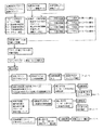
FIG. 2 is a perspective view showing a configuration of a main part of the copying apparatus of FIG. 1 and a control system thereof.
FIG. 3 is a diagram illustrating a state in which a pattern is formed between recording sheets.
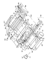
FIG. 4 is a perspective view showing a main part of the copying apparatus in which a pattern according to the first embodiment of the invention is transferred onto a conveying belt.
FIG. 5 is an enlarged view of the pattern of FIG. 4;
6 is a diagram for explaining an operation for correcting color misregistration of an image using the pattern of FIG. 4;
FIG. 7 is a diagram showing a pattern according to another embodiment.
FIG. 8 is a schematic diagram illustrating a forcing mechanism that corrects the position of the conveyor belt.
9 is a block diagram showing a control system that controls the operation of the forcing mechanism of FIG. 8;
FIG. 10 is a diagram for explaining a conventional color misregistration correction method.
[Explanation of symbols]
1 ... Copier,
9Y, 9M, 9C, 9K ... drum motor,
10Y, 10M, 10C, 10K ... Image forming unit,
11Y, 11M, 11C, 11K ... photosensitive drum,
12Y, 12M, 12C, 12K ... charging device,
13Y, 13M, 13C, 13K ... developing device,
14Y, 14M, 14C, 14K ... transfer device,
15Y, 15M, 15C, 15K ... cleaning device,
20 ... transport mechanism,
21 ... Conveyor belt,
22 ... belt motor,
24 ... Driving roller,
26 ... driven roller,
38a, 38b ... sensors,
40 ... Belt cleaner,
50. Fixing device,
60 ... exposure device,
98 ... CCD image sensor,
101: Image memory,
102 ... an image processing unit,
104: Laser light emitting device,
106: Clock counter,
109 ... pattern for detection,
112, 114 ... motor driver,
120: Setting circuit
P: Recording paper.
Claims (6)
上記複数の画像を保持して第1の方向へ搬送する搬送手段と、
上記第1の方向と直交する第2の方向に沿って互いに平行に延び、上記第1の方向に沿って等間隔で揃えられた一端をそれぞれ有し、上記第1の方向に沿って上記第2の方向に所定長さづつ短くなるように形成された複数本の線分を有するパターンを上記搬送手段上に出力するためのパターンデータを記憶した記憶手段と、
第1の画像を上記搬送手段上に出力するとともに、上記記憶手段にて記憶されたパターンデータに基づいて、上記第1の画像の出力位置を示すパターンとしての第1のパターンを上記搬送手段上に出力する第1の画像形成手段と、
上記第1の画像に重ね合わせて第2の画像を出力するとともに、上記記憶手段にて記憶されたパターンデータに基づいて、上記第2の画像の出力位置を示すパターンとしての第2のパターンを上記第1の方向に沿って上記第1のパターンに隣接して出力する第2の画像形成手段と、
上記搬送手段に対向して設けられ、上記第1の方向へ搬送される上記第1および第2のパターンを順次検出する検出手段と、
上記検出手段にて検出された上記第1および第2のパターンの線分の本数を比較し、該本数が一致するように、上記第1および第2の画像形成手段によって出力される上記第1および第2の画像の出力位置を上記第2の方向に沿って補正する補正手段と、
を備えていることを特徴とする画像形成装置。In an image forming apparatus that outputs a plurality of images superimposed,
Conveying means for holding the plurality of images and conveying them in a first direction;
Extending parallel to each other along a second direction orthogonal to the first direction, each having one end aligned at equal intervals along the first direction, and the first direction along the first direction . Storage means for storing pattern data for outputting a pattern having a plurality of line segments formed so as to be shortened by a predetermined length in the direction of 2 on the transport means;
The first image is output on the transport unit, and a first pattern as a pattern indicating the output position of the first image is output on the transport unit based on the pattern data stored in the storage unit. First image forming means for outputting to
A second image is output by superimposing the first image, and a second pattern as a pattern indicating the output position of the second image is output based on the pattern data stored in the storage means. A second image forming means for outputting adjacent to the first pattern along the first direction;
A detecting means provided opposite to the conveying means and sequentially detecting the first and second patterns conveyed in the first direction;
The number of line segments of the first and second patterns detected by the detecting means is compared, and the first and second image forming means output the first and second image forming means so that the numbers match. Correction means for correcting the output position of the second image along the second direction;
An image forming apparatus comprising:
上記複数の画像を保持して第1の方向へ搬送する搬送手段と、
上記第1の方向と直交する第2の方向に沿って延びた第1の線分、および上記第1の線分から上記第1の方向に対して傾斜した方向に互いに平行且つ等間隔で延びた複数本の第2の線分を有するパターンを上記搬送手段上に出力するためのパターンデータを記憶した記憶手段と、
第1の画像を上記搬送手段上に出力するとともに、上記記憶手段にて記憶されたパターンデータに基づいて、上記第1の画像の出力位置を示すパターンとしての第1のパターンを上記搬送手段上に出力する第1の画像形成手段と、
上記第1の画像に重ね合わせて第2の画像を出力するとともに、上記記憶手段にて記憶されたパターンデータに基づいて、上記第2の画像の出力位置を示すパターンとしての第2のパターンを上記第1の方向に沿って上記第1のパターンに隣接して出力する第2の画像形成手段と、
上記搬送手段に対向して設けられ、上記第1の方向へ搬送される上記第1および第2のパターンを順次検出する検出手段と、
上記検出手段にて検出された上記第1および第2のパターンの線分の本数を比較し、該本数が一致するように、上記第1および第2の画像形成手段によって出力される上記第1および第2の画像の出力位置を上記第2の方向に沿って補正する補正手段と、
を備えていることを特徴とする画像形成装置。In an image forming apparatus that outputs a plurality of images superimposed,
Conveying means for holding the plurality of images and conveying them in a first direction;
The first line segment extending along a second direction orthogonal to the first direction, and the first line segment and the first line segment extend in parallel with each other at equal intervals in a direction inclined with respect to the first direction. Storage means for storing pattern data for outputting a pattern having a plurality of second line segments onto the transport means;
The first image is output on the transport unit, and a first pattern as a pattern indicating the output position of the first image is output on the transport unit based on the pattern data stored in the storage unit. First image forming means for outputting to
A second image is output by superimposing the first image, and a second pattern as a pattern indicating the output position of the second image is output based on the pattern data stored in the storage means. A second image forming means for outputting adjacent to the first pattern along the first direction;
A detecting means provided opposite to the conveying means and sequentially detecting the first and second patterns conveyed in the first direction;
The number of line segments of the first and second patterns detected by the detecting means is compared, and the first and second image forming means output the first and second image forming means so that the numbers match. Correction means for correcting the output position of the second image along the second direction;
An image forming apparatus comprising:
上記複数の画像を保持して第1の方向へ搬送する搬送手段と、
上記第1の方向と直交する第2の方向に沿って互いに平行且つ等間隔で延びた複数本の線分、および上記各線分間に設けられ上記第1の方向に対して傾斜した方向にズレて配置された複数のドットを有するパターンを上記搬送手段上に出力するためのパターンデータを記憶した記憶手段と、
第1の画像を上記搬送手段上に出力するとともに、上記記憶手段にて記憶されたパターンデータに基づいて、上記第1の画像の出力位置を示すパターンとしての第1のパターンを上記搬送手段上に出力する第1の画像形成手段と、
上記第1の画像に重ね合わせて第2の画像を出力するとともに、上記記憶手段にて記憶されたパターンデータに基づいて、上記第2の画像の出力位置を示すパターンとしての第2のパターンを上記第1の方向に沿って上記第1のパターンに隣接して出力する第2の画像形成手段と、
上記搬送手段に対向して設けられ、上記第1の方向へ搬送される上記第1および第2のパターンを順次検出する検出手段と、
上記検出手段にて上記第1および第2のパターンのドットが検出されるまでに検出された上記第1および第2のパターンの線分の本数を比較し、該本数が一致するように、上記第1および第2の画像形成手段によって出力される上記第1および第2の画像の出力位置を上記第2の方向に沿って補正する補正手段と、
を備えていることを特徴とする画像形成装置。In an image forming apparatus that outputs a plurality of images superimposed,
Conveying means for holding the plurality of images and conveying them in a first direction;
A plurality of line segments extending parallel to each other at equal intervals along a second direction orthogonal to the first direction, and shifted in a direction inclined with respect to the first direction provided in each line segment. Storage means for storing pattern data for outputting a pattern having a plurality of arranged dots on the conveying means;
The first image is output on the transport unit, and a first pattern as a pattern indicating the output position of the first image is output on the transport unit based on the pattern data stored in the storage unit. First image forming means for outputting to
A second image is output by superimposing the first image, and a second pattern as a pattern indicating the output position of the second image is output based on the pattern data stored in the storage means. A second image forming means for outputting adjacent to the first pattern along the first direction;
A detecting means provided opposite to the conveying means and sequentially detecting the first and second patterns conveyed in the first direction;
The number of line segments of the first and second patterns detected until the dots of the first and second patterns are detected by the detecting means are compared, and the numbers are matched so that the numbers match. Correction means for correcting the output positions of the first and second images output by the first and second image forming means along the second direction;
An image forming apparatus comprising:
上記被画像形成媒体を保持するとともに第1の方向へ搬送する搬送手段と、
上記色分解された複数の画像データを記憶するとともに、上記第1の方向と直交する第2の方向に沿って互いに平行に延び、上記第1の方向に沿って等間隔で揃えられた一端をそれぞれ有し、上記第1の方向に沿って上記第2の方向に所定長さづつ短くなるように形成された複数本の線分を有するパターンを上記搬送手段上に出力するためのパターンデータを記憶した記憶手段と、
上記記憶手段にて記憶された複数の画像データの上記被画像形成媒体上での出力位置を示すパターンとして、上記記憶手段にて記憶されたパターンデータを上記各画像データにそれぞれ合成し、該画像データの出力位置を設定し、所定のタイミングで出力する画像処理手段と、
上記画像処理手段から出力される画像データに基づいて、上記搬送手段にて搬送される被画像形成媒体上に第1の画像を形成するとともに、上記第1の画像に合成された第1のパターンを上記搬送手段上に形成する第1の画像形成手段と、
上記画像処理手段から出力される画像データに基づいて、上記搬送手段にて搬送される被画像形成媒体上で上記第1の画像に重ね合わせて第2の画像を形成するとともに、上記第2の画像に合成された第2のパターンを上記第1の方向に沿って上記第1のパターンに隣接して形成する第2の画像形成手段と、
上記搬送手段に対向して配置され、上記第1の方向へ搬送される上記第1および第2のパターンを順次検出する検出手段と、
上記検出手段にて上記第1および第2のパターンの最長の線分が検出されるタイミングに基づいて、上記第1および第2の画像形成手段によって出力される上記第1および第2の画像の出力位置を上記第1の方向に沿って補正し、上記第1および第2のパターンの線分の本数を比較し、該本数が一致するように、上記第1および第2の画像の出力位置を上記第2の方向に沿って補正する補正手段と、
を備えていることを特徴とする画像形成装置。In an image forming apparatus for forming a color image by sequentially superimposing the plurality of images on an image forming medium based on a plurality of color-separated image data,
Conveying means for holding the image forming medium and conveying the image forming medium in a first direction;
The plurality of color-separated image data are stored, and one end that extends in parallel with each other along a second direction orthogonal to the first direction and is aligned at equal intervals along the first direction is arranged. Pattern data for outputting on the transport means a pattern having a plurality of line segments each having a length that is shorter in the second direction along the first direction by a predetermined length. Memorized storage means;
The pattern data stored in the storage unit is combined with the image data as a pattern indicating the output position on the image forming medium of the plurality of image data stored in the storage unit, and the image data Image processing means for setting an output position of data and outputting the data at a predetermined timing;
Based on the image data output from the image processing means, a first image is formed on the image forming medium transported by the transport means and is combined with the first image. A first image forming means for forming the image on the conveying means;
Based on the image data output from the image processing unit, a second image is formed on the image forming medium transported by the transport unit by superimposing the first image, and the second image is formed. A second image forming means for forming a second pattern combined with the image adjacent to the first pattern along the first direction;
A detecting means arranged to face the conveying means and sequentially detecting the first and second patterns conveyed in the first direction;
Based on the timing at which the detection means detects the longest line segments of the first and second patterns, the first and second image output means output the first and second images. The output positions of the first and second images are corrected so that the output positions are corrected along the first direction, the numbers of line segments of the first and second patterns are compared, and the numbers match. Correction means for correcting the value along the second direction;
An image forming apparatus comprising:
上記被画像形成媒体を保持するとともに第1の方向へ搬送する搬送手段と、
上記色分解された複数の画像データを記憶するとともに、上記第1の方向と直交する第2の方向に沿って延びた第1の線分、および上記第1の線分から上記第1の方向に対して傾斜した方向に互いに平行且つ等間隔で延びた複数本の第2の線分を有するパターンを上記搬送手段上に出力するためのパターンデータを記憶した記憶手段と、
上記記憶手段にて記憶された複数の画像データの上記被画像形成媒体上での出力位置を示すパターンとして、上記記憶手段にて記憶されたパターンデータを上記各画像データにそれぞれ合成し、該画像データの出力位置を設定し、所定のタイミングで出力する画像処理手段と、
上記画像処理手段から出力される画像データに基づいて、上記搬送手段にて搬送される被画像形成媒体上に第1の画像を形成するとともに、上記第1の画像に合成された第1のパターンを上記搬送手段上に形成する第1の画像形成手段と、
上記画像処理手段から出力される画像データに基づいて、上記搬送手段にて搬送される被画像形成媒体上で上記第1の画像に重ね合わせて第2の画像を形成するとともに、上記第2の画像に合成された第2のパターンを上記第1の方向に沿って上記第1のパターンに隣接して形成する第2の画像形成手段と、
上記搬送手段に対向して配置され、上記第1の方向へ搬送される上記第1および第2のパターンを順次検出する検出手段と、
上記検出手段にて上記第1および第2のパターンの第1の線分が検出されるタイミングに基づいて、上記第1および第2の画像形成手段によって出力される上記第1および第2の画像の出力位置を上記第1の方向に沿って補正し、上記第1および第2のパターンの第2の線分の本数を比較し、該本数が一致するように、上記第1および第2の画像の出力位置を上記第2の方向に沿って補正する補正手段と、
を備えていることを特徴とする画像形成装置。In an image forming apparatus for forming a color image by sequentially superimposing the plurality of images on an image forming medium based on a plurality of color-separated image data,
Conveying means for holding the image forming medium and conveying the image forming medium in a first direction;
Storing a plurality of color-separated image data, a first line segment extending in a second direction orthogonal to the first direction, and the first line segment in the first direction; Storage means for storing pattern data for outputting a pattern having a plurality of second line segments extending in parallel to each other at equal intervals in a direction inclined with respect to the conveying means;
The pattern data stored in the storage unit is combined with the image data as a pattern indicating the output position on the image forming medium of the plurality of image data stored in the storage unit, and the image data Image processing means for setting an output position of data and outputting the data at a predetermined timing;
Based on the image data output from the image processing means, a first image is formed on the image forming medium transported by the transport means and is combined with the first image. A first image forming means for forming the image on the conveying means;
Based on the image data output from the image processing unit, a second image is formed on the image forming medium transported by the transport unit by superimposing the first image, and the second image is formed. A second image forming means for forming a second pattern combined with the image adjacent to the first pattern along the first direction;
A detecting means arranged to face the conveying means and sequentially detecting the first and second patterns conveyed in the first direction;
The first and second images output by the first and second image forming means based on the timing at which the detection means detects the first line segments of the first and second patterns. Are corrected along the first direction, the number of the second line segments of the first and second patterns is compared, and the first and second are matched so that the numbers match. Correction means for correcting the output position of the image along the second direction;
An image forming apparatus comprising:
上記被画像形成媒体を保持するとともに第1の方向へ搬送する搬送手段と、
上記色分解された複数の画像データを記憶するとともに、上記第1の方向と直交する第2の方向に沿って互いに平行且つ等間隔で延びた複数本の線分、および上記各線分間に設けられ上記第1の方向に対して傾斜した方向にズレて配置された複数のドットを有するパターンを上記搬送手段上に出力するためのパターンデータを記憶した記憶手段と、
上記記憶手段にて記憶された複数の画像データの上記被画像形成媒体上での出力位置を示すパターンとして、上記記憶手段にて記憶されたパターンデータを上記各画像データにそれぞれ合成し、該画像データの出力位置を設定し、所定のタイミングで出力する画像処理手段と、
上記画像処理手段から出力される画像データに基づいて、上記搬送手段にて搬送される被画像形成媒体上に第1の画像を形成するとともに、上記第1の画像に合成された第1のパターンを上記搬送手段上に形成する第1の画像形成手段と、
上記画像処理手段から出力される画像データに基づいて、上記搬送手段にて搬送される被画像形成媒体上で上記第1の画像に重ね合わせて第2の画像を形成するとともに、上記第2の画像に合成された第2のパターンを上記第1の方向に沿って上記第1のパターンに隣接して形成する第2の画像形成手段と、
上記搬送手段に対向して配置され、上記第1の方向へ搬送される上記第1および第2のパターンを順次検出する検出手段と、
上記検出手段にて上記第1および第2のパターンの上記第1の方向に沿った端部の線分が検出されるタイミングに基づいて、上記第1および第2の画像形成手段によって出力される上記第1および第2の画像の出力位置を上記第1の方向に沿って補正し、上記第1および第2のパターンのドットが検出されるまでに検出された線分の本数を比較し、該本数が一致するように、上記第1および第2の画像の出力位置を上記第2の方向に沿って補正する補正手段と、
を備えていることを特徴とする画像形成装置。In an image forming apparatus for forming a color image by sequentially superimposing the plurality of images on an image forming medium based on a plurality of color-separated image data,
Conveying means for holding the image forming medium and conveying the image forming medium in a first direction;
The plurality of color-separated image data are stored and provided in a plurality of line segments extending in parallel with each other at equal intervals along a second direction orthogonal to the first direction, and the line segments. Storage means storing pattern data for outputting a pattern having a plurality of dots arranged in a direction inclined with respect to the first direction onto the transport means;
The pattern data stored in the storage unit is combined with the image data as a pattern indicating the output position on the image forming medium of the plurality of image data stored in the storage unit, and the image data Image processing means for setting an output position of data and outputting the data at a predetermined timing;
Based on the image data output from the image processing means, a first image is formed on the image forming medium transported by the transport means and is combined with the first image. A first image forming means for forming the image on the conveying means;
Based on the image data output from the image processing unit, a second image is formed on the image forming medium transported by the transport unit by superimposing the first image, and the second image is formed. A second image forming means for forming a second pattern combined with the image adjacent to the first pattern along the first direction;
A detecting means arranged to face the conveying means and sequentially detecting the first and second patterns conveyed in the first direction;
Output by the first and second image forming means based on the timing at which the detection means detects the line segments of the end portions along the first direction of the first and second patterns. Correcting the output positions of the first and second images along the first direction, comparing the number of line segments detected until the dots of the first and second patterns are detected, Correction means for correcting the output positions of the first and second images along the second direction so that the numbers match;
An image forming apparatus comprising:
Priority Applications (3)
| Application Number | Priority Date | Filing Date | Title |
|---|---|---|---|
| JP32164796A JP3762003B2 (en) | 1996-12-02 | 1996-12-02 | Image forming apparatus |
| CN97123035A CN1184960A (en) | 1996-12-02 | 1997-12-01 | image forming device |
| US08/982,353 US5995717A (en) | 1996-12-02 | 1997-12-02 | Image forming apparatus |
Applications Claiming Priority (1)
| Application Number | Priority Date | Filing Date | Title |
|---|---|---|---|
| JP32164796A JP3762003B2 (en) | 1996-12-02 | 1996-12-02 | Image forming apparatus |
Publications (2)
| Publication Number | Publication Date |
|---|---|
| JPH10161385A JPH10161385A (en) | 1998-06-19 |
| JP3762003B2 true JP3762003B2 (en) | 2006-03-29 |
Family
ID=18134844
Family Applications (1)
| Application Number | Title | Priority Date | Filing Date |
|---|---|---|---|
| JP32164796A Expired - Fee Related JP3762003B2 (en) | 1996-12-02 | 1996-12-02 | Image forming apparatus |
Country Status (3)
| Country | Link |
|---|---|
| US (1) | US5995717A (en) |
| JP (1) | JP3762003B2 (en) |
| CN (1) | CN1184960A (en) |
Families Citing this family (30)
| Publication number | Priority date | Publication date | Assignee | Title |
|---|---|---|---|---|
| KR100212318B1 (en) * | 1997-05-29 | 1999-08-02 | 윤종용 | Vertical alignment correcting apparatus and method |
| JP2000242249A (en) * | 1999-02-22 | 2000-09-08 | Fuji Xerox Co Ltd | Image processor |
| JP4447700B2 (en) | 1999-09-29 | 2010-04-07 | 東芝テック株式会社 | Image forming apparatus |
| JP4422250B2 (en) | 1999-09-29 | 2010-02-24 | 東芝テック株式会社 | Image forming apparatus |
| US6317147B1 (en) * | 2000-06-13 | 2001-11-13 | Toshiba Tec Kabushiki Kaisha | Image forming method using registration marks having varying angles |
| JP2002091123A (en) * | 2000-07-14 | 2002-03-27 | Ricoh Co Ltd | Color image forming apparatus and toner replenishing apparatus |
| JP2002137455A (en) * | 2000-11-07 | 2002-05-14 | Matsushita Electric Ind Co Ltd | Printer controller |
| US6560434B2 (en) | 2001-01-18 | 2003-05-06 | Lexmark International, Inc. | Intermediate transfer member motion control via surface wheel feedback |
| US6408157B1 (en) | 2001-02-16 | 2002-06-18 | Toshiba Tec Kabushiki Kaisha | Image forming apparatus |
| US6906832B2 (en) * | 2001-03-27 | 2005-06-14 | Kabushiki Kaisha Toshiba | Image forming apparatus with function of tilt adjustment to laser-beam reflecting mirror |
| JP4371257B2 (en) * | 2002-12-02 | 2009-11-25 | 株式会社リコー | Image forming apparatus |
| JP4091899B2 (en) * | 2002-12-20 | 2008-05-28 | 株式会社リコー | Belt drive |
| JP4381009B2 (en) * | 2003-03-12 | 2009-12-09 | 新光電気工業株式会社 | Pattern drawing apparatus, pattern drawing method, and inspection apparatus |
| US7257358B2 (en) * | 2003-12-19 | 2007-08-14 | Lexmark International, Inc. | Method and apparatus for detecting registration errors in an image forming device |
| US7313352B2 (en) * | 2004-03-09 | 2007-12-25 | Ricoh Company, Ltd. | Image forming apparatus, method of controlling same, machine-readable medium and process cartridge |
| CN100432861C (en) * | 2004-08-19 | 2008-11-12 | 株式会社理光 | Image forming apparatus |
| JP4654708B2 (en) * | 2005-02-18 | 2011-03-23 | 富士ゼロックス株式会社 | Image forming apparatus |
| JP4723955B2 (en) * | 2005-08-31 | 2011-07-13 | 株式会社リコー | Image forming apparatus |
| JP4530166B2 (en) * | 2005-09-08 | 2010-08-25 | セイコーエプソン株式会社 | Optical sensor correction value acquisition method and recording apparatus |
| US7967407B2 (en) | 2006-02-03 | 2011-06-28 | R.R. Donnelley | Use of a sense mark to control a printing system |
| JP5058512B2 (en) * | 2006-05-11 | 2012-10-24 | キヤノン株式会社 | Printing apparatus and printing method |
| JP4973038B2 (en) * | 2006-07-10 | 2012-07-11 | 富士ゼロックス株式会社 | Image forming apparatus and program thereof |
| US8753026B2 (en) * | 2007-06-29 | 2014-06-17 | R.R. Donnelley & Sons Company | Use of a sense mark to control a printing system |
| US9098903B2 (en) * | 2009-07-21 | 2015-08-04 | R.R. Donnelley & Sons Company | Systems and methods for detecting alignment errors |
| US8179412B2 (en) * | 2009-08-19 | 2012-05-15 | Eastman Kodak Company | Merging image pixels based on main-scan misalignment |
| US8174552B2 (en) * | 2009-08-19 | 2012-05-08 | Eastman Kodak Company | Merging of image pixel arrangements |
| JP5586918B2 (en) * | 2009-10-30 | 2014-09-10 | キヤノン株式会社 | Movement detection apparatus and recording apparatus |
| JP5586919B2 (en) * | 2009-10-30 | 2014-09-10 | キヤノン株式会社 | Movement detection apparatus and recording apparatus |
| JP2011133870A (en) * | 2009-11-27 | 2011-07-07 | Canon Inc | Image forming device and control method therefor |
| US10370214B2 (en) | 2017-05-31 | 2019-08-06 | Cryovac, Llc | Position control system and method |
Family Cites Families (4)
| Publication number | Priority date | Publication date | Assignee | Title |
|---|---|---|---|---|
| JPS63292163A (en) * | 1987-05-26 | 1988-11-29 | Ricoh Co Ltd | Image forming device |
| US5384592A (en) * | 1992-11-16 | 1995-01-24 | Xerox Corporation | Method and apparatus for tandem color registration control |
| JP3275434B2 (en) * | 1993-03-29 | 2002-04-15 | 富士ゼロックス株式会社 | Color registration error correction device |
| JPH08278680A (en) * | 1995-04-05 | 1996-10-22 | Toshiba Corp | Image forming apparatus and method of controlling image forming apparatus |
-
1996
- 1996-12-02 JP JP32164796A patent/JP3762003B2/en not_active Expired - Fee Related
-
1997
- 1997-12-01 CN CN97123035A patent/CN1184960A/en active Pending
- 1997-12-02 US US08/982,353 patent/US5995717A/en not_active Expired - Fee Related
Also Published As
| Publication number | Publication date |
|---|---|
| JPH10161385A (en) | 1998-06-19 |
| US5995717A (en) | 1999-11-30 |
| CN1184960A (en) | 1998-06-17 |
Similar Documents
| Publication | Publication Date | Title |
|---|---|---|
| JP3762003B2 (en) | Image forming apparatus | |
| JP3377779B2 (en) | Image forming apparatus and image forming method | |
| JP4838461B2 (en) | Image forming apparatus | |
| JP5163378B2 (en) | Paper conveying apparatus and image forming apparatus | |
| US7697876B2 (en) | Image forming apparatus and control method for registration mark detection | |
| US5896472A (en) | Image forming apparatus | |
| JP3288072B2 (en) | Image forming device | |
| US7636540B2 (en) | Belt driving unit and, method of switching the control loop between a normal and abnormal control loop | |
| US6246857B1 (en) | Image forming apparatus | |
| JPH1144853A (en) | Multi-beam optical device and image forming apparatus provided with the multi-beam optical device | |
| JP3768942B2 (en) | Image forming apparatus | |
| JP2000071522A (en) | Image-forming apparatus | |
| JP4832260B2 (en) | Meander detection device and image forming apparatus | |
| JPH10235928A (en) | Optical scanning device and image forming apparatus | |
| JP4343550B2 (en) | Image forming apparatus | |
| JP4437846B2 (en) | Image forming apparatus | |
| JP3920868B2 (en) | Image forming apparatus | |
| JP2008009107A (en) | Image forming apparatus | |
| JP2006301405A (en) | Image forming apparatus | |
| US20220373957A1 (en) | Image forming apparatus and image forming method | |
| JP4738002B2 (en) | Image forming apparatus | |
| JPH10186250A (en) | Optical scanning device and image forming apparatus | |
| JP2008129485A (en) | Speed controller and image forming apparatus | |
| JPH11231725A (en) | Image forming device | |
| JP4728010B2 (en) | Image forming apparatus |
Legal Events
| Date | Code | Title | Description |
|---|---|---|---|
| A977 | Report on retrieval |
Free format text: JAPANESE INTERMEDIATE CODE: A971007 Effective date: 20050401 |
|
| A131 | Notification of reasons for refusal |
Free format text: JAPANESE INTERMEDIATE CODE: A131 Effective date: 20050809 |
|
| A521 | Request for written amendment filed |
Free format text: JAPANESE INTERMEDIATE CODE: A523 Effective date: 20051011 |
|
| TRDD | Decision of grant or rejection written | ||
| A01 | Written decision to grant a patent or to grant a registration (utility model) |
Free format text: JAPANESE INTERMEDIATE CODE: A01 Effective date: 20060110 |
|
| A61 | First payment of annual fees (during grant procedure) |
Free format text: JAPANESE INTERMEDIATE CODE: A61 Effective date: 20060112 |
|
| R150 | Certificate of patent or registration of utility model |
Free format text: JAPANESE INTERMEDIATE CODE: R150 |
|
| FPAY | Renewal fee payment (event date is renewal date of database) |
Free format text: PAYMENT UNTIL: 20100120 Year of fee payment: 4 |
|
| FPAY | Renewal fee payment (event date is renewal date of database) |
Free format text: PAYMENT UNTIL: 20100120 Year of fee payment: 4 |
|
| FPAY | Renewal fee payment (event date is renewal date of database) |
Free format text: PAYMENT UNTIL: 20110120 Year of fee payment: 5 |
|
| FPAY | Renewal fee payment (event date is renewal date of database) |
Free format text: PAYMENT UNTIL: 20110120 Year of fee payment: 5 |
|
| FPAY | Renewal fee payment (event date is renewal date of database) |
Free format text: PAYMENT UNTIL: 20120120 Year of fee payment: 6 |
|
| FPAY | Renewal fee payment (event date is renewal date of database) |
Free format text: PAYMENT UNTIL: 20120120 Year of fee payment: 6 |
|
| FPAY | Renewal fee payment (event date is renewal date of database) |
Free format text: PAYMENT UNTIL: 20130120 Year of fee payment: 7 |
|
| LAPS | Cancellation because of no payment of annual fees |