JP3758001B2 - Apparatus and method for efficient haze containment by hood - Google Patents
Apparatus and method for efficient haze containment by hood Download PDFInfo
- Publication number
- JP3758001B2 JP3758001B2 JP17704097A JP17704097A JP3758001B2 JP 3758001 B2 JP3758001 B2 JP 3758001B2 JP 17704097 A JP17704097 A JP 17704097A JP 17704097 A JP17704097 A JP 17704097A JP 3758001 B2 JP3758001 B2 JP 3758001B2
- Authority
- JP
- Japan
- Prior art keywords
- vortex chamber
- diode
- vortex
- hood
- air
- Prior art date
- Legal status (The legal status is an assumption and is not a legal conclusion. Google has not performed a legal analysis and makes no representation as to the accuracy of the status listed.)
- Expired - Fee Related
Links
Images


Description
【0001】
本発明は蒸気を含有し、その拡散を防止する通気性のある囲いに関する。そのような囲いは一般的にヒュームフードとして知られている。本発明は、さらに具体的には、内部への出入りを可能にするように開けることが出来るヒュームフードに関する。ここにおいて、該開口によって煙霧をフードの外部に意図せずして漏出させてしまう可能性がある。本発明は、最も具体的には、進入速度および組成調整された空気(make-up air) の体積を制御するヒュームフードに関する。
【0002】
作業場からの揮発性物質、特に毒性物質の拡散を防止すること、およびそれらの物質を扱う人による毒性物質等の吸入を防ぐことが望ましい、工業的・科学的設備では、ヒュームフードはよく知られている。フードは、作業者の手または腕のみが入る装置から、一人以上の人が入れる大きな装置および大きな設備に至るまで、様々な大きさを取り得る。典型的には、フードは、フード中に毒性物質などの含有されていない空気を取り入れ、予め決められた(時々変えることができる)割合でフードの内側から、フードから離れた安全な排出点に空気と煙霧とを排出する排気システムを備える囲いを有する。垂直方向に滑らせることの出来るドアやサッシのような、閉めることの出来る囲いの開口部によって、一般に、空気がフード中に入り、フード中で行われる操作に伴う人と装置との必要に応じた関わりが可能になる。
【0003】
ヒュームフードを使用するに当たっての共通の目標は、前記ドアが開いている場合にドアから煙霧が逆流して漏出するのを防止することである。1つの方策は、ドアが開いている間はフードを通る気流を増加させることである。しかしながら、気流が増えると、フード中の乱気流を増加させる可能性があり、それによって、実際に煙霧の乗った空気が単発的にドアから追い出される可能性が生じる。さらに、フード中に導入され、次いで大気中に排出される空気は、多少費用がかかっても人間が快適であるために調整されている可能性があり、それ故に流速の大きなフードはエネルギーの浪費であり、運転に費用がかかる。
【0004】
ウィギンらに、1988年5月3日付で発行された米国特許 No. 4,741,257 は、フードの内側および外側の空気圧を測定し、フードに入る空気の流れを調節して圧力差を一定に維持する制御システムを開示している。フードのドアまたはサッシが開かれているか、または閉じられている場合は、差圧のバランスを取り直して、サッシの位置に関わらず、フードの「フェース」または何もない領域を通る空気の速度を一定にするために、システムは入ってくる空気の流れを増加させたり減らしたりする。この制御システムの根底にある仮定は、フードのフェースを通る空気の速度を一定に保つことが最適な制御方法であるということである。逆流を防止するためには、何が最適な差圧で、したがって何がフードを通過する最適な気流であるかを扱っていないので、この仮定は必ずしも正確ではない。このシステムによって統治される流れは、調整された空気を浪費する可能性もある。全体の体積を減らすことによってエネルギーは節約される可能性があるが、発明者によってなされた微量のガスの研究は、可変体積固定フェース速度制御を使用することによってはヒュームフードは本質的により安全にはならないことを示した。異なる設計を採用し、異なる寸法を有するヒュームフードは、最適の流速および流量が異なっている可能性があり、それはまた、フードの外側の絶対および変動圧、フードの前面における気流および活性、フードの内側の負荷、並びにフードに入る組成調整された空気(make-up air) の温度を含む環境条件の影響を受けやすい。
【0005】
典型的な上方排気フードは基本的に2つの区域を有している。それは、下方の面速度作業室、およびその上方の排気システムを与える渦を有している場合がある第二室である。前記渦の強度および安定性は、フードに入る空気の面速度よりも逆流を制御するにあたって実質的に重要度が大きいことに気付いた。流速が非常に小さい場合には、渦は不安定で明瞭に現れず、開いているサッシを通って逆流が起こる可能性がある。気流が速すぎる場合には、渦は崩れるか破壊され、煙霧の乗った柱をフードフェースから噴出させる激しい気流の動きに取って代わられる可能性がある。気流が適切に調節されていると、円滑な渦が上方の室に形成され、下方の作業室からの煙霧を効率よく捕え、排出口へと気流を運び、フェースを通っての煙霧の逆流を防止する。
【0006】
後で記載する方法によって決定することのできる、渦室の側壁のある重要な位置において、渦室とフードの外側との間に重要な差圧が存在する。この差圧はフードを通って流れる空気の体積およびフェースの開いている領域の割合に伴って変化する。安定した渦は層流を形成しており、これらの条件下で渦中の前記重要な位置におかれたセンサーは、渦室の内部とフードの外部との間に最小の圧力変動を検出する。この条件はフードを通る最適の気流および最適の差圧を示している。しかしながら、渦が不安定な状況下では、センサーは、上方の室を通る激しい、または混沌とした流れと結びついたわずかな圧力変動を検出する。本発明の動的な制御システムは、下方の室から渦室への組成調整空気(make-up air) の流れを変えて、安定した渦を形成し、それによって感知される圧力の変化を最小にするために、圧力変動のフィードバック感知を使用する。
【0007】
境界壁での渦圧の測定は、水位計の .000015 インチのオーダーで、リアルタイムでの速度圧の測定をすることの出来る差圧変換器を必要とする。膜の質量および移動距離が大き過ぎ、また、反応時間が長過ぎるので、公知の機械的差圧の振れのセンサーは不十分である。公知の熱線抵抗温度デバイス(RTD's) またはサーミスタは、リアルタイムの測定では第一段階で十分な利得を与えることが出来ない。
【0008】
ヒュームフードの渦室における乱気流を最小にする改良された装置および方法を提供することが本発明の主要な目的である。
【0009】
ヒュームフードからの煙霧を含む空気の向流逃げを最小にする改良された制御手段を提供することが本発明の更なる目的である。
【0010】
.000015" wc 以下程度に小さい差圧を検出する改良された反応の早いセンサーを提供することが本発明のまた更なる目的である。
【0011】
一定時間内に使用される組成調整空気(make-up air) の量を最小限にしつつ、ヒュームフードの煙霧含有能を最大にする改良された装置および方法を提供することが本発明のまた更なる目的である。
【0012】
簡単に述べると、本発明によるシステムは、作業室の上にある渦室の壁の重要で決定することの出来る位置に置かれた反応の速い差圧センサーを有する。操作状態においては、渦室の低い圧力のために、センサーを通ってフードの外側から渦室に入る空気のわずかで連続的な流れがある。渦室における圧力の非常に小さく非常に速い変化をシステムが検出すると、システムは渦が不安定になったと推定し、渦に出入りする気流を変化させて乱気流を減らして渦を安定化するために、1つ以上の可動板を調節する駆動信号を発する。このセンサーは、フードの操作者に潜在的に危険な逆流状態を警告するための警報システムの一部として非制御方式で使用してもよい。
【0013】
センサーは、信号変換器として機能する抵抗ブリッジの対向する脚に、一対の整合した線形熱ツェナーダイオードを有する。該ダイオードの1つは放熱子に結合されており、整合されたセンサーを機械的にアンバランスにし、電子的な変動を防止するセンサー間に固定熱損失バイアスを与える。ブリッジ回路は2段出力増幅器を有する。センサーは全く同じ金属管片で遮蔽されていて、それらはゴムのスペーサによってダイオードから離されている。そして、熱ダイオード上を通過する空気による冷却に差動的に反応する。フードの内側と外側との間の差圧における変動を直接示すように、空気の速度は検量されている。例えば、ブリッジの2ボルトの出力を .000015" wc の増幅変動に対応させることが出来る。
【0014】
固定熱作動機械的構造と結びついた線形ダイオードは、渦室の壁で、渦の完全度と安定度とを示すわずかな圧力の変化の測定を可能にする。新しい入口のノズルおよび空気力学的ピックアップ形状は、ビルのHVAC脈動や風などのフードの外側のノイズ源からの類似する大きさの望ましくないエネルギー波を、受け付けない。
【0015】
全てのフードに適用することの出来る、普遍的なセンサーの最適位置はない。渦室の高さおよび奥行き、並びにフェースの2つの異なる大きさの開口部において測定された面空気速度の比に基づいて、私はいかなるフードについても最適の位置を決定することの出来る方法と数学式を得た。
【0016】
センサーおよび増幅器を含むブリッジ回路は、リアルタイムの信号を比例積分アルゴリズムおよび適応利得アルゴリズムを有する専用のアナログコントローラーに送る、渦差圧変換器である。前記コントローラーの出力は、渦室に入る組成調整空気(make-up air) の体積を変化させるためにフード中のバイパス空気ダンパーの位置を変える作動装置に送られる。この制御システムは、センサーによって最小の圧力変動が感知される、即ち安定した渦の存在を示している、ダンパー位置を捜す。渦室からの出口における第2のダンパーも、渦室を通る適切な空気の流れを得る助けとなるように制御システムによって操作されてもよい。制御ダンパーの動作範囲内で最小位置が得られなければ、出力信号はフードの排気ダンパーを作動させて、排気扇を回転を落とし、システムが制御ダンパーによる制御の範囲内に入るようにする。
【0017】
この技術は、単一の排気システムに結合されている多数の排煙フードを制御するのに特に有用である。ある建造物内の様々な位置にある多数のフードを最適に働かせるように中央排気システムを調整するのは不可能である。ヒュームフードの使用者を保護するために、フード内のダンパーを操作することによってどのようにして渦を最適化することが出来るかについての発見は、操作者の安全という点において非常に重要な前進である。もし、何らかの理由によって、排気ダンパーおよびバイパスダンパーを操作することによって渦を安定にすることが出来なければ、安全ではない状態の警報を発するようにシステムを改良することが出来る。この警報は、従来技術に開示されているような面速度に基づくものではなく、排煙フードの捕捉品質に基づく。フードのフェース面積が小さい場合(ドアが殆ど閉まっている)には低い面速度が使用されるので、この技術によってエネルギーを節約することもできる。
【0018】
現在のところ好ましい態様と共に、本発明の前記および他の目的、特徴および効果は、添付の図面を参照する以下の記載を読むことによって一層明らかとなるであろう。
【0019】
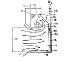
図1には、フードの中への、フードの内部での、およびフードからの空気の動きを制御または指示する様々な要素を含む筐体12を有する代表的な従来技術のヒュームフードが示されている。垂直に滑らせることができるドアまたはサッシ14によって、作業者および空気のフードへの出入りのため開口部またはフェース16を調節することができる。フードの内部は作業室18とその上方の渦室20を有し、作業用ライト21を有していてもよい。排気用煙突22はファン24を備えており(図1には示されていない)、ファンはフェース16および床に接する入口17からフード中へ空気を引き入れ、筐体12の開口部から空気を追い出す。前期フードの入口からの気流は、主としてフェース16から入り、後部板26の方に流れて、角度のついた板28へと上ってゆく。角度の付いた板28は気流を回転させて円筒状の渦30に導入するのを助ける。フードの床を流れる気流を与えるために、フードは第2の気流路を有している。板26および28は後部壁32から離して設置されており、通路33を形成している。板26および28は上部34からも離れており、渦室20からの出口36を形成している。さらに、板は底部38からも離れており、下部口40を形成している。板26は通路33に通じる中間孔42を有していてもよい。
【0020】
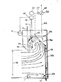
図2は、本発明の一態様に従って変形されたフード10を示している。以下にもっと詳しく記載されており、図9に示されているが、電子ブリッジ回路の向かい合う脚に配置されている整合させた一対の熱ツェナーダイオードを有する動的差圧変換器45の感知ステージ44は、フードの側壁46の穴の外側に配置されており、渦室中の圧力のごくわずかな変化に起因する、穴を通る気流のわずかな変化を感知して気流の乱れを示す。気流の乱れは渦が存在しないか不完全に形成されており、煙霧がフードのフェースから逃げている可能性があるという不安定で望ましくない状態を示している。そのような変化が感知された場合は、前期ダイオード間の熱的に誘導された電気的不均衡に起因する信号が、信号増幅器を含み、好ましくはフードの外に配置されている変換器の第2ステージに送られる。リアルタイムで増幅された信号は帰還制御装置50、好ましくは、比例積分および適応利得アルゴリズムを有する、図10に図式的に示されているアナログコンピュータに送られる。その信号は警報機51にも送られてもよく、警報機は予め定められた警報限界を与える変化させることのできる閾値弁別装置を有していてもよい。制御装置50の出力は作動装置52、好ましくはサーボステッピングDCモーター作動装置へ送られる。作動装置は、接続チェーンまたはケーブル58によって出口ダンパー54およびバイパスダンパー56を同期させて動かす。渦中にさらに空気を入れるためには、底部スロット40を通過するバイパス空気をさらに制限するためにバイパスダンパー56を動かし、出口スロット36を更に開けるために出口ダンパー54を動かす。逆に、渦中に流れ込む空気を少なくするためには、通路33へ空気をバイパスさせるために底部スロットを開け、出口スロット36が絞られる。システムは、センサー44からの信号における変化がゼロになる状態を求めており、変化がゼロであることは渦室に安定な渦が存在することを示す。もし、ゼロの状態が得られなければ、システムはフードを通る全気流が不適切であると推測して、全気流を変化させるために、第2作動装置53に排気煙突中のスロットルダンパー55を作動させる。
【0021】
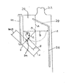
フードの側壁における圧力センサーの正しい位置は、どのフードについても、以下の手続によって図3に示されるように決定することができる。
【0022】
第一に、フロアスイープバイパスなどの全ての入口を密閉し、フェースを通っての空気の通過のみを可能にする。サッシを最大解放位置まで開ける。
【0023】
第二に、例えば、排気ファンの速度を変えたり、排気ダンパーを調節することによって、フードの排気量を平均的なフェース速度である1分当たり100 フィートにセットする。
【0024】
第三に、サッシを50%閉め、平均フェース速度を測定する。
【0025】
第四に、第三段階で得られた値で 100 を割り、R2と呼ばれる純フードインデックス数を得る。
【0026】
R2=100 fpm/平均フェース速度fpm (1)
第五に、頂上部および前面のそれぞれの中間部において、渦室の高さAと深さBとをそれぞれ測定し、次式によってAとBとの直交点に原点Oを有する半径Cを計算するのに測定値を使用する。
【0027】
C={√(2.98xAB/ π) }/2 (2)
第六に、原点Oからフェースの開口部Fの上端までの距離Dを測定し、この値からCを引いてXを得る。
【0028】
X=D−C (3)
第七に、Z=X/2を取って、次の式によって配置ファクターbを計算する。
b=Z(R2 )
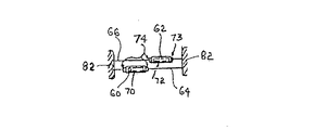
第八に、前記開口部Fから線Dに沿って(b+Z) の距離にセンサーを配置する。感知素子の構造は図4〜6に示されている。第一熱ダイオード60と第二熱ダイオード62は、熱に対する反応において、電気的に全く同じであり、図9に示すように、電子ブリッジ45のそれぞれの脚64および66に接続されている。各ダイオードはある長さの薄壁の金属管70および72によってそれぞれシールドされており、シールド用の前記管は、例えば、長さ0.220 インチ、外径0.094 インチ、壁厚0.006 インチの真鍮の管など、大きさおよび材料において全く同じである。各管はゴムのスペーサ74によってダイオードから絶縁されており、センサーのガラスビーズとシールド管との間に均一な空気間隙を有している。ダイオード60はブリッジにおける参照ダイオードである。ダイオード62の周囲の管72は、ダイオードのアノードのリード線に半田付けすることによって機械的に取り付けられており、感知ダイオードとしてのダイオード62に機械的なヒートシンク73を与えている。ダイオード60からよりダイオード62からの方が熱は速く放散される。平衡電流ブリッジは、ブリッジの両脚を通じて一定電流を維持しようとするが、ダイオードを横切って通過する空気が抵抗と電流の不均衡を生じさせ、ブリッジから搬送出力信号を発生する。
【0029】
この機械的に誘発された電気的混乱はいくつかの利点を提供する。第一に、前記機械的に誘発された不均衡は決して変化しない。その結果、公知の電子不均衡技術では経験された可能性のある、2つのセンサー間での経時ドリフトがない。第二に、線形熱ダイオードと金属シールド管との組み合わせは、低温での高利得感知を実現し、熱線型熱抵抗温度装置では起こる可能性のある汚れの焼き付きを防ぐことができる。第三に、この構成で使用されるダイオードは水位計(WC)の0.000015インチ程度に低い差圧を感知することができ、DC2ボルトのブリッジから増幅された出力を伝えることができる。
【0030】
このシールドを有する熱ダイオードは、センサー筐体82の窓80におけるそれぞれのリード76および78に固定されている。これらリードは、第一および第二増幅器86および88並びに電子ブリッジの他の公知の抵抗器を有する第二ステージ48の入力リードへケーブル84を介して接続されている。前記窓の端部は夾角の入口角度αが約60度になるように面取りされているのが好ましい。前記窓の喉部90は約0.322 インチの幅であるのが好ましい。
【0031】
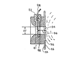
図7および8に示されているように、センサー筐体82は側壁の孔94に隣接するフードの側壁46の外表面93に取り付けられている据付台92の窪孔に配置されている。据付台92は実質的に円形で孔94を取り囲んでいるのが好ましい。フードの外側で発生する圧力パルスの形態のノイズはダイオードで感知され、誤った信号の発生に帰する可能性があるので、据付台92は、フードの外側からの関係のないパルスを効果的に減衰させることのできる環状ノズルであるのが好ましい。好ましい態様においては、ダイオードは側壁46の内側の表面98から、0.2 インチと3.4 ンチとの間の距離96をおいて配置されており、孔94は0.690 インチの直径95を有している。窪孔91の端部から始まって、据付台92のノズルの形状は曲率半径97が0.600 インチで開口部の直径100 が1.5 インチ、据付台92の窪孔91迄の深さが0.388 インチである点まで外側に湾曲している。直径100 の位置を越えると、据付台の表面は外側に湾曲し、直径95の約4倍であって据付深さが0.450 インチである開口部の直径102 の位置まで、予想される操作圧力範囲内での空気の流れ対ヒュームフードの差圧の平方根関数のおよその写しである実質的に放物線形の入口湾曲を示している。直径102 の位置の外側は、幅が0.031 インチで側壁46に実質的に平行である平面的な環状表面103 である。
【0032】
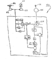
ヒュームフードの渦の制御は時間によって変化する非線形プロセスであるので、適応性のあるアルゴリズムの使用によってリアルタイムで制御される。図10に示されている自己適応利得コントローラー50は様々なループ利得を補償し、異なる複数のサッシ位置でコントローラーの調整をする人間のヒュームフードオペレーターの代わりをする。図10における記号はコントローラー50の構成部品について一般に受け入れられている名称であって、制御アルゴリズムを記載している。(図示されている)アナログまたはデジタル制御ループのどちらでも前記制御アルゴリズムを実行することができる。応答速度という観点から、デジタル制御よりもアナログ制御が好ましい。
【0033】
適応性のあるコントローラーは、リアルタイム制御の要件を損なうことなく、システム制動を調整する。渦が安定であるときは、制動は必要なく、比例帯域は狭い。しかしながら、乱れが生じると、周波数帯域に偏差を分散させることによって帯域は広くなる。発振が正常であれば、それらは高周波チャネルを通り抜ける。すると、信号は整流され、結果は正および負偏差アダプタに送られる。積分器はコントローラーの比例帯域を増加させることによって偏差に比例して応答する。同時に、偏差の低周波数帯域は利得Kによって増幅され、整流され、積分器に送られる。オフセット、ドリフトまたは反応の遅滞があると、積分器はコントローラーの比例帯域を減少させて渦を初期の位置に戻す。
【0034】
渦差圧変換器45は、図11に示されるように、孤立(stand-alone) フード警報システムの部品としても使用することができる。本発明の渦制御装置を備えていないフードについては、フードが適切な気流制御下になく、煙霧の逆流が起こる可能性がある時をオペレーターが知っていることは重要である。変換器45の出力信号を、搬送信号から警報信号を区別する臨界判別器を有する警報機51に直接送ってもよい。
【0035】
前記記載から、改良された装置が提供され、最適にフード中に煙霧を動的に封じ込める方法が明らかになったであろう。本願装置および方法においては、渦室におけるある重要な位置で差圧が感知され、渦室を通過する気流はしっかりした渦を維持するために制御下に変化を与えられる。ここに記載されている装置および方法の、本発明に従った変更および修正は、当業者には疑うことなく明らかであろう。したがって、前記記載は例示的であると理解されるべきで、限定的な意味に解釈されるべきではない。
【図面の簡単な説明】
図1は渦の感知および積極的な制御を行っていない従来技術のフードの縦断面図である。
図2は、本発明による渦感知および制御要素を示す図1と同様の縦断面図である。
図3は、渦圧センサーの正しい配置を説明するヒュームフード渦室の概略断面図である。
図4は、センサーにおける熱ダイオードの据え付けを示している。
図5は、センサーの平面図である。
図6は、図5における6-6 の線に沿ったセンサーの断面図である。
図7は、渦室の側壁を通って延びるノズル部材に操作のために配置されたセンサーの断面図である。
図8は、ノズルが渦室の外側からの望ましくない圧力波を受け付けないようにする寸法を示す、図7のノズルの入口の曲線の断面図である。
図9は、図4および6に示されているセンサーを含む動的渦圧変換器の設計線図である。
図10は、前記渦圧変換器からの入力信号をヒュームフード邪魔板調節サーボ機構および排気ダンパーへの出力信号に変換する適応性利得コントローラーの設計線図である。
図11は、本発明の渦圧センサーおよび変換器を含むヒュームフード性能警報機を備えたフードの概略縦断面図である。[0001]
The present invention relates to a breathable enclosure containing steam and preventing its diffusion. Such an enclosure is commonly known as a fume hood. More specifically, the present invention relates to a fume hood that can be opened to allow access to the interior. Here, there is a possibility that the smoke may unintentionally leak outside the hood due to the opening. The present invention relates most particularly to a fume hood that controls the speed of entry and the volume of make-up air.
[0002]
Fume hoods are well known in industrial and scientific facilities where it is desirable to prevent the diffusion of volatile substances from the workplace, especially toxic substances, and to prevent inhalation of toxic substances by those who handle them. ing. Hoods can vary in size, from devices that contain only the hands or arms of an operator, to large devices and large equipment that can be accommodated by one or more people. Typically, a hood takes air that does not contain toxic substances into the hood and at a predetermined (which can be changed from time to time) from the inside of the hood to a safe discharge point away from the hood. An enclosure with an exhaust system for exhausting air and fumes. Closed enclosure openings, such as doors and sashes that can be slid vertically, generally allow air to enter the hood and as needed by the person and equipment involved in the operation performed in the hood Can be involved.
[0003]
A common goal in using a fume hood is to prevent backflowing and leaking of fumes from the door when the door is open. One strategy is to increase the airflow through the hood while the door is open. However, an increase in airflow can increase turbulence in the hood, which can cause the air that is actually smoky to be expelled from the door on a single occasion. Furthermore, the air introduced into the hood and then exhausted into the atmosphere may be adjusted for human comfort at some cost, so a high flow hood is a waste of energy. It is expensive to drive.
[0004]
US Patent No. 4,741,257 issued to Wiggin et al. On May 3, 1988, measures the air pressure inside and outside the hood and regulates the flow of air into the hood to maintain a constant pressure differential A system is disclosed. If the hood door or sash is open or closed, rebalance the differential pressure so that the air velocity through the hood “face” or empty area, regardless of the position of the sash. To keep it constant, the system increases or decreases the incoming air flow. The underlying assumption of this control system is that the optimal control method is to keep the air velocity through the face of the hood constant. This assumption is not necessarily accurate because it does not address what is the optimal differential pressure and thus what is the optimal airflow through the hood to prevent backflow. The flow governed by this system can waste conditioned air. Although energy may be saved by reducing the overall volume, the study of trace gases made by the inventor has shown that the fume hood is inherently safer by using variable volume fixed face speed control. Showed that it should not. Fume hoods that employ different designs and have different dimensions may have different optimum flow rates and flow rates, which also include absolute and fluctuating pressure outside the hood, airflow and activity at the front of the hood, Susceptible to environmental conditions, including inner loads, as well as the temperature of make-up air entering the hood.
[0005]
A typical upper exhaust hood basically has two zones. It is a second chamber that may have a lower surface velocity working chamber and a vortex that provides an exhaust system above it. It has been found that the strength and stability of the vortex is substantially more important in controlling the backflow than the surface velocity of the air entering the hood. If the flow velocity is very small, the vortices are unstable and do not appear clearly, and backflow may occur through the open sash. If the airflow is too fast, the vortex may collapse or be destroyed and replaced by a violent airflow movement that causes the fumed column to erupt from the hood face. When the airflow is properly adjusted, a smooth vortex is formed in the upper chamber, which efficiently captures the fumes from the lower working chamber, carries the airflow to the outlet, and reverses the fumes through the face. To prevent.
[0006]
There is an important differential pressure between the vortex chamber and the outside of the hood at an important location on the side wall of the vortex chamber, which can be determined by the method described later. This differential pressure varies with the volume of air flowing through the hood and the percentage of the face open area. A stable vortex forms a laminar flow, and under these conditions the sensor placed in the critical position in the vortex detects minimal pressure fluctuations between the interior of the vortex chamber and the exterior of the hood. This condition indicates the optimal airflow through the hood and the optimal differential pressure. However, under conditions where the vortex is unstable, the sensor detects slight pressure fluctuations associated with intense or chaotic flow through the upper chamber. The dynamic control system of the present invention alters the flow of make-up air from the lower chamber to the vortex chamber to form a stable vortex, thereby minimizing the perceived pressure change. In order to achieve this, feedback sensing of pressure fluctuations is used.
[0007]
Measurement of vortex pressure at the boundary wall requires a differential pressure transducer that can measure velocity pressure in real time on the order of .000015 inches on a water level gauge. Because the membrane mass and distance traveled are too large and the reaction time is too long, the known mechanical differential pressure fluctuation sensors are inadequate. Known hot-wire resistance temperature devices (RTD's) or thermistors cannot provide sufficient gain in the first stage for real-time measurements.
[0008]
It is a primary object of the present invention to provide an improved apparatus and method that minimizes turbulence in the swirl chamber of a fume hood.
[0009]
It is a further object of the present invention to provide an improved control means that minimizes counterflow escape of air containing fumes from the fume hood.
[0010]
It is a still further object of the present invention to provide an improved responsive sensor that detects differential pressures as low as .000015 "wc or less.
[0011]
It is a further object of the present invention to provide an improved apparatus and method for maximizing the fume hood's fume content while minimizing the amount of make-up air used within a period of time. Is the purpose.
[0012]
Briefly, the system according to the present invention has a responsive differential pressure sensor located at a critical and determinable location on the wall of the vortex chamber above the working chamber. In the operating state, due to the low pressure of the vortex chamber, there is a slight continuous flow of air that enters the vortex chamber from the outside of the hood through the sensor. When the system detects a very small and very fast change in pressure in the vortex chamber, the system assumes that the vortex has become unstable, and changes the airflow entering and exiting the vortex to reduce turbulence and stabilize the vortex A drive signal for adjusting one or more movable plates is generated. This sensor may be used in an uncontrolled manner as part of an alarm system to alert a hood operator of a potentially dangerous backflow condition.
[0013]
The sensor has a pair of matched linear thermal Zener diodes on opposite legs of a resistive bridge that functions as a signal converter. One of the diodes is coupled to a heat sink and provides a fixed heat loss bias between the sensors that mechanically unbalances the matched sensor and prevents electronic fluctuations. The bridge circuit has a two-stage output amplifier. The sensors are shielded by exactly the same metal tube pieces, which are separated from the diodes by rubber spacers. It reacts differentially to cooling by air passing over the thermal diode. The air velocity is calibrated to directly show the variation in the differential pressure between the inside and outside of the hood. For example, a 2 volt output of the bridge can be matched to an amplification variation of .000015 "wc.
[0014]
A linear diode coupled with a fixed thermally actuated mechanical structure allows the measurement of slight pressure changes at the walls of the vortex chamber, indicating vortex integrity and stability. The new inlet nozzle and aerodynamic pickup geometry do not accept similarly sized undesirable energy waves from noise sources outside the hood, such as building HVAC pulsations and wind.
[0015]
There is no universal sensor optimum position that can be applied to all hoods. Based on the height and depth of the vortex chamber and the ratio of the surface air velocities measured at the two differently sized openings in the face, I am able to determine the optimal position and math for any hood. Got the formula.
[0016]
The bridge circuit, including sensors and amplifiers, is a vortex differential pressure transducer that sends real-time signals to a dedicated analog controller with a proportional integration algorithm and an adaptive gain algorithm. The output of the controller is sent to an actuator that changes the position of the bypass air damper in the hood to change the volume of make-up air entering the vortex chamber. This control system looks for a damper position where a minimum pressure fluctuation is sensed by the sensor, ie indicating the presence of a stable vortex. A second damper at the exit from the vortex chamber may also be operated by the control system to help obtain adequate air flow through the vortex chamber. If the minimum position cannot be obtained within the operating range of the control damper, the output signal activates the exhaust damper of the hood and causes the exhaust fan to turn down so that the system is within the control range of the control damper.
[0017]
This technique is particularly useful for controlling multiple smoke hoods that are coupled to a single exhaust system. It is impossible to adjust the central exhaust system to optimally work with multiple hoods at various locations within a building. The discovery of how vortices can be optimized by manipulating dampers in the hood to protect the fume hood user is a very important advance in terms of operator safety It is. If for some reason the vortex cannot be stabilized by operating the exhaust damper and bypass damper, the system can be modified to issue an unsafe condition alarm. This alarm is not based on the surface speed as disclosed in the prior art, but on the captured quality of the smoke hood. This technique can also save energy because a lower face speed is used when the hood face area is small (the door is almost closed).
[0018]
The above and other objects, features and advantages of the present invention, as well as presently preferred embodiments, will become more apparent upon reading the following description with reference to the accompanying drawings.
[0019]
FIG. 1 illustrates a typical prior art fume hood having a
[0020]
FIG. 2 illustrates a hood 10 that has been modified in accordance with an embodiment of the present invention. As described in more detail below and shown in FIG. 9, the
[0021]
The correct position of the pressure sensor on the side wall of the hood can be determined for any hood as shown in FIG. 3 by the following procedure.
[0022]
First, all inlets, such as floor sweep bypasses, are sealed, allowing only air to pass through the face. Open the sash to the maximum release position.
[0023]
Second, the hood displacement is set to an average face speed of 100 feet per minute, for example by changing the speed of the exhaust fan or adjusting the exhaust damper.
[0024]
Third, close the
[0025]
Fourth, divide the 100 values obtained in the third step, to obtain a pure hood index number called R 2.
[0026]
R 2 = 100 fpm / average face speed fpm (1)
Fifth, measure the height A and depth B of the vortex chamber at the middle of the top and front, respectively, and calculate the radius C having the origin O at the orthogonal point of A and B by the following formula Use measurements to do this.
[0027]
C = {√ (2.98xAB / π)} / 2 (2)
Sixth, the distance D from the origin O to the upper end of the opening F of the face is measured, and C is subtracted from this value to obtain X.
[0028]
X = D-C (3)
Seventh, taking Z = X / 2, the placement factor b is calculated by the following equation.
b = Z (R 2 )
Eighth, a sensor is disposed at a distance of (b + Z) along the line D from the opening F. The structure of the sensing element is shown in FIGS. The first thermal diode 60 and the second
[0029]
This mechanically induced electrical disturbance provides several advantages. First, the mechanically induced imbalance never changes. As a result, there is no drift over time between the two sensors that may have been experienced with known electronic imbalance techniques. Second, the combination of a linear thermal diode and a metal shield tube provides high gain sensing at low temperatures and can prevent soil burn-in that can occur with hot wire thermal resistance temperature devices. Third, the diode used in this configuration can sense differential pressures as low as 0.000015 inches of the water level gauge (WC) and can deliver the amplified output from a
[0030]
The thermal diode having this shield is fixed to the respective leads 76 and 78 in the
[0031]
As shown in FIGS. 7 and 8, the
[0032]
Since the control of the fume hood vortex is a time-varying non-linear process, it is controlled in real time by the use of an adaptive algorithm. The self-
[0033]
An adaptive controller coordinates system braking without compromising real-time control requirements. When the vortex is stable, no braking is necessary and the proportional band is narrow. However, when disturbance occurs, the band is widened by dispersing the deviation in the frequency band. If the oscillations are normal, they pass through the high frequency channel. The signal is then rectified and the result is sent to the positive and negative deviation adapters. The integrator responds proportionally to the deviation by increasing the proportional band of the controller. At the same time, the low frequency band of the deviation is amplified by the gain K, rectified and sent to the integrator. When there is an offset, drift or reaction delay, the integrator reduces the proportional band of the controller and returns the vortex to its initial position.
[0034]
The vortex
[0035]
From the foregoing, it will be apparent that an improved device is provided and optimally a method for dynamically containing fumes in the hood. In the present apparatus and method, differential pressure is sensed at certain critical locations in the vortex chamber, and the airflow passing through the vortex chamber is varied under control to maintain a firm vortex. Changes and modifications to the apparatus and methods described herein in accordance with the present invention will be apparent to those skilled in the art. Therefore, the above description should be understood as illustrative and should not be construed in a limiting sense.
[Brief description of the drawings]
FIG. 1 is a longitudinal sectional view of a prior art hood without vortex sensing and active control.
FIG. 2 is a longitudinal sectional view similar to FIG. 1 showing vortex sensing and control elements according to the present invention.
FIG. 3 is a schematic cross-sectional view of a fume hood vortex chamber illustrating the correct placement of the vortex pressure sensor.
FIG. 4 shows the installation of the thermal diode in the sensor.
FIG. 5 is a plan view of the sensor.
FIG. 6 is a cross-sectional view of the sensor along line 6-6 in FIG.
FIG. 7 is a cross-sectional view of a sensor disposed for operation on a nozzle member extending through the side wall of the vortex chamber.
FIG. 8 is a cross-sectional view of the nozzle inlet curve of FIG. 7 showing dimensions that prevent the nozzle from receiving unwanted pressure waves from outside the vortex chamber.
FIG. 9 is a design diagram of a dynamic eddy pressure transducer including the sensor shown in FIGS.
FIG. 10 is a design diagram of an adaptive gain controller that converts an input signal from the vortex pressure converter into an output signal to a fume hood baffle plate adjusting servo mechanism and an exhaust damper.
FIG. 11 is a schematic longitudinal sectional view of a hood provided with a fume hood performance alarm including the eddy pressure sensor and the converter of the present invention.
Claims (17)
a)渦差圧変換器、
b)前記渦差圧変換器からの増幅された信号を受け取り、該信号を加工し、コントローラー出力信号を与える電子コントローラー、
c)前記電子コントローラーからの前記出力信号に応答する作動装置、および
d)前記バイパス通路にあって前記作動装置によって作動可能であり、前記排気システムへと前記バイパス通路を通って行く空気の量を変化させることによって、前記渦室を通過する空気の量を変化させる制動機
を有するシステム。In a fume hood having an adjustable opening leading to the working chamber, a vortex chamber above the working chamber, and an exhaust system having a fan, the vortex chamber is variably bypassed through the passage to the exhaust system. Dynamically controlling the amount of airflow passing through
a) Vortex differential pressure transducer,
b) an electronic controller that receives the amplified signal from the vortex differential pressure transducer, processes the signal, and provides a controller output signal;
c) an actuator responsive to the output signal from the electronic controller; and
d) changing the amount of air passing through the vortex chamber by changing the amount of air that is in the bypass passage and is operable by the actuating device and passes through the bypass passage to the exhaust system; A system with a trigger.
a)前記渦室の通路中に配置されており、渦室の壁を貫通する孔に近接して配置されている、渦室とフードの外側との間の差圧における変化を感知するセンサー、および
b)前記センサーからの信号を増幅する演算増幅器
を含む電子平衡ブリッジを有する、請求項1によるシステム。The converter is
a) a sensor for detecting a change in the pressure difference between the vortex chamber and the outside of the hood, which is arranged in the passage of the vortex chamber and is arranged close to a hole penetrating the wall of the vortex chamber; and
2. The system according to claim 1, comprising an electronic balance bridge comprising an operational amplifier for amplifying the signal from the sensor.
C={√(2.98xAB/π)}/2=垂直平面におけるOからの半径
X=D−C 線Dに沿って
Z=X/2
R 2 =フードの広く開けたフェースを通る1分当たり 100 フィートの空気速度をフェースの開口面積を 50 %縮小したときの平均空気速度で割った値
b=Z(R 2 )
によって算出される b と Z とを用いて、Fから (b+Z) の距離にあることを特徴とする、請求項1によるシステム。The optimum position of the hole in the wall of the vortex chamber is such that F is the position of the upper end of the face opening leading to the working chamber and O is the height of the vortex chamber at the respective midpoints of the top and front of the vortex chamber. The following calculation C = {√ (2.98xAB / π)} / 2 = in the vertical plane along the line of length D connecting F and O when the orthogonal point between the depth A and the depth B is taken Radius from O X = DC Along line D Z = X / 2
R 2 = Air velocity of 100 feet per minute through the wide open face of the hood divided by the average air velocity when the face opening area is reduced by 50 %
b = Z (R 2 )
The system according to claim 1, characterized in that it is at a distance of (b + Z) from F using b and Z calculated by .
a)前記空気の通路に配置されており、温度によってその抵抗値が変わり、前記電子平衡ブリッジの対向する脚に電気的導線によって結合されている、第一及び第二熱反応ダイオード、
b)前記第一および第二ダイオードの周囲にそれぞれ配置されている第一および第二ダイオードシールドであって、前記第一ダイオードが参照用ダイオードであり、第二ダイオードが信号用ダイオードであり、該第二シールドは前記第二ダイオード導線に熱伝導可能に取り付けられて第二ダイオードからのヒートシンクを形成し、
c)前記第一および第二ダイオードとの間の抵抗差に比例する前記ブリッジの電圧出力を制御する、帰還ループ中の第一および第二演算増幅器、
を有するセンサー装置。A bridge that operatively reacts to temperature changes in opposing legs, the magnitude of the reaction being directly related to the velocity of air passing over the opposing legs, the air velocity being in the opposing legs Directly related to the resulting dynamic differential pressure,
a) first and second thermal reaction diodes disposed in the air passage, the resistance value of which varies with temperature, and is coupled to opposite legs of the electronic balance bridge by electrical conductors;
b) first and second diode shields disposed around the first and second diodes, respectively, wherein the first diode is a reference diode and the second diode is a signal diode; The second shield is attached to the second diode conductor so as to be thermally conductive to form a heat sink from the second diode ;
c) first and second operational amplifiers in a feedback loop that control the voltage output of the bridge proportional to the resistance difference between the first and second diodes;
Having a sensor device.
a)前記渦に曝される渦室において、Fを作業室に通じるフェース開口部の上端部の位置とし、Oを渦室の頂上部および前部のそれぞれの中間点における渦室の高さAと深さBとの直交点としたときに、FとOとを結ぶ長さDの線に沿って、次の計算
C={√( 2.98xAB/ π)} /2 =垂直平面におけるOからの半径
X=D−C 線Dに沿って
Z=X/2
R 2 =フードの広く開けたフェースを通る1分当たり 100 フィートの空気速度をフェースの開口面積を 50 %縮小したときの平均空気速度で割った値
b=Z(R 2 )
によって算出される b と Z とを用いて、Fから (b+Z) の距離にある位置において、渦室の内側とフードの外側との差圧の変化を測定し、
b)前記作業室を通って渦室へ入る空気の流れを、前記差圧の変化が最小になるまで変化させる
という手順を有する方法。A method of optimizing the performance of a fume hood having a vortex chamber above a work chamber by dynamically optimizing vortex stability in the vortex chamber,
a) In the vortex chamber exposed to the vortex , F is the position of the upper end of the face opening leading to the working chamber, and O is the height A of the vortex chamber at the respective midpoints of the top and front of the vortex chamber. Along the line of length D connecting F and O, where
C = {√ ( 2.98xAB / π)} / 2 = radius from O in the vertical plane
X = D-C along line D
Z = X / 2
R 2 = Air velocity of 100 feet per minute through the wide open face of the hood divided by the average air velocity when the face opening area is reduced by 50 %
b = Z (R 2 )
Measure the change in the pressure difference between the inside of the vortex chamber and the outside of the hood at a position at a distance of (b + Z) from F using b and Z calculated by
b) A method comprising the steps of changing the flow of air entering the vortex chamber through the working chamber until the change in the differential pressure is minimized.
Priority Applications (1)
| Application Number | Priority Date | Filing Date | Title |
|---|---|---|---|
| JP17704097A JP3758001B2 (en) | 1997-07-02 | 1997-07-02 | Apparatus and method for efficient haze containment by hood |
Applications Claiming Priority (1)
| Application Number | Priority Date | Filing Date | Title |
|---|---|---|---|
| JP17704097A JP3758001B2 (en) | 1997-07-02 | 1997-07-02 | Apparatus and method for efficient haze containment by hood |
Publications (2)
| Publication Number | Publication Date |
|---|---|
| JPH1137522A JPH1137522A (en) | 1999-02-12 |
| JP3758001B2 true JP3758001B2 (en) | 2006-03-22 |
Family
ID=16024101
Family Applications (1)
| Application Number | Title | Priority Date | Filing Date |
|---|---|---|---|
| JP17704097A Expired - Fee Related JP3758001B2 (en) | 1997-07-02 | 1997-07-02 | Apparatus and method for efficient haze containment by hood |
Country Status (1)
| Country | Link |
|---|---|
| JP (1) | JP3758001B2 (en) |
Cited By (1)
| Publication number | Priority date | Publication date | Assignee | Title |
|---|---|---|---|---|
| KR101744595B1 (en) * | 2015-11-23 | 2017-06-08 | 삼에이치텍 주식회사 | Constant pressure control system of multi fume hood for energy saving |
Families Citing this family (3)
| Publication number | Priority date | Publication date | Assignee | Title |
|---|---|---|---|---|
| EP1250556B8 (en) * | 2000-01-10 | 2009-04-08 | OY Halton Group, Ltd. | Exhaust hood with air curtain |
| KR100561808B1 (en) * | 2005-05-16 | 2006-03-21 | 주식회사 석문이엔지 | Fan filter unit with means of air reverse flow prevention |
| CN110207353B (en) * | 2019-05-21 | 2020-04-21 | 武汉理工大学 | Vortex ring generating device based on radial disturbance principle |
-
1997
- 1997-07-02 JP JP17704097A patent/JP3758001B2/en not_active Expired - Fee Related
Cited By (1)
| Publication number | Priority date | Publication date | Assignee | Title |
|---|---|---|---|---|
| KR101744595B1 (en) * | 2015-11-23 | 2017-06-08 | 삼에이치텍 주식회사 | Constant pressure control system of multi fume hood for energy saving |
Also Published As
| Publication number | Publication date |
|---|---|
| JPH1137522A (en) | 1999-02-12 |
Similar Documents
| Publication | Publication Date | Title |
|---|---|---|
| EP0888831B1 (en) | Apparatus and method to optimize a fume hood | |
| EP0610224B1 (en) | Fume hood controller | |
| US6853946B2 (en) | Air flow sensing and control for animal confinement system | |
| US6131463A (en) | Apparatus and method to optimize fume containment by a hood | |
| US5415583A (en) | Fume hood air flow control system | |
| US9335057B2 (en) | Real-time control of exhaust flow | |
| US4548128A (en) | Fume hood | |
| ES2394872T3 (en) | Detection of obstructions and interruptions of an aspirated smoke detector (ASD) | |
| US4343194A (en) | Flow sensing apparatus | |
| CA2632195A1 (en) | Converting existing prior art fume hoods into high performance low airflow stable vortex fume hoods | |
| JP3758001B2 (en) | Apparatus and method for efficient haze containment by hood | |
| US20030027514A1 (en) | Fume hood with alarm system | |
| US6820501B2 (en) | Differential static pressure measuring and activating device and control mechanism | |
| US6450875B1 (en) | Monitoring air entry velocity into fume hood | |
| WO1997042467A1 (en) | Inverted venturi flow element for measuring fluid velocity in a conduit | |
| KR920004778A (en) | Combustor Control | |
| JP2015150465A (en) | draft chamber | |
| JPS5970913A (en) | Front surface inflow air flow velocity measuring and display apparatus of draft chamber | |
| GB2129928A (en) | A fume hood | |
| JPS6363937A (en) | Industrial gas measuring apparatus | |
| EP3885057B1 (en) | A fume hood and a method for operating a fume hood | |
| JP3511582B2 (en) | Active noise control device | |
| JPH0753707Y2 (en) | Exhaust control device for draft chamber | |
| Breum et al. | Differences in organic vapor concentrations in the breathing zone resulting from convective transport from spillage on clothing | |
| JPS6314248Y2 (en) |
Legal Events
| Date | Code | Title | Description |
|---|---|---|---|
| A621 | Written request for application examination |
Free format text: JAPANESE INTERMEDIATE CODE: A621 Effective date: 20040625 |
|
| A977 | Report on retrieval |
Free format text: JAPANESE INTERMEDIATE CODE: A971007 Effective date: 20050414 |
|
| A131 | Notification of reasons for refusal |
Free format text: JAPANESE INTERMEDIATE CODE: A131 Effective date: 20050422 |
|
| A601 | Written request for extension of time |
Free format text: JAPANESE INTERMEDIATE CODE: A601 Effective date: 20050721 |
|
| A602 | Written permission of extension of time |
Free format text: JAPANESE INTERMEDIATE CODE: A602 Effective date: 20050726 |
|
| A521 | Written amendment |
Free format text: JAPANESE INTERMEDIATE CODE: A523 Effective date: 20051024 |
|
| A524 | Written submission of copy of amendment under section 19 (pct) |
Free format text: JAPANESE INTERMEDIATE CODE: A524 Effective date: 20051024 |
|
| TRDD | Decision of grant or rejection written | ||
| A01 | Written decision to grant a patent or to grant a registration (utility model) |
Free format text: JAPANESE INTERMEDIATE CODE: A01 Effective date: 20051125 |
|
| A61 | First payment of annual fees (during grant procedure) |
Free format text: JAPANESE INTERMEDIATE CODE: A61 Effective date: 20051220 |
|
| R150 | Certificate of patent or registration of utility model |
Free format text: JAPANESE INTERMEDIATE CODE: R150 |
|
| FPAY | Renewal fee payment (event date is renewal date of database) |
Free format text: PAYMENT UNTIL: 20100113 Year of fee payment: 4 |
|
| FPAY | Renewal fee payment (event date is renewal date of database) |
Free format text: PAYMENT UNTIL: 20110113 Year of fee payment: 5 |
|
| FPAY | Renewal fee payment (event date is renewal date of database) |
Free format text: PAYMENT UNTIL: 20110113 Year of fee payment: 5 |
|
| FPAY | Renewal fee payment (event date is renewal date of database) |
Free format text: PAYMENT UNTIL: 20120113 Year of fee payment: 6 |
|
| FPAY | Renewal fee payment (event date is renewal date of database) |
Free format text: PAYMENT UNTIL: 20130113 Year of fee payment: 7 |
|
| LAPS | Cancellation because of no payment of annual fees |