JP3757656B2 - Warp knitting for air belt cover, air belt cover and air belt device - Google Patents
Warp knitting for air belt cover, air belt cover and air belt device Download PDFInfo
- Publication number
- JP3757656B2 JP3757656B2 JP00669299A JP669299A JP3757656B2 JP 3757656 B2 JP3757656 B2 JP 3757656B2 JP 00669299 A JP00669299 A JP 00669299A JP 669299 A JP669299 A JP 669299A JP 3757656 B2 JP3757656 B2 JP 3757656B2
- Authority
- JP
- Japan
- Prior art keywords
- air belt
- belt
- cover
- knitting
- air
- Prior art date
- Legal status (The legal status is an assumption and is not a legal conclusion. Google has not performed a legal analysis and makes no representation as to the accuracy of the status listed.)
- Expired - Lifetime
Links
Images


Description
【0001】
【発明の属する技術分野】
本発明は、車両衝突時等に車両乗員を保護するために、シートベルトの一部を袋状ベルトとし、ガス発生装置からのガスによって該袋状ベルトを膨張させるようにしたエアベルト装置の該袋状ベルトを被覆するためのエアベルトカバー用のたて編み物に関する。また、本発明は、このエアベルトカバー用たて編み物を用いたエアベルトカバー及びエアベルト装置に関する。
【0002】
【従来の技術及び先行技術】
この種のエアベルト装置として、本出願人は、先に、膨張可能なエアベルトと、該エアベルト内にガスを供給して膨張させるガス発生器とを備えてなり、該エアベルトは、帯状となるように折り畳まれた袋状ベルトと、該袋状ベルトを囲んでいるカバーとを備えてなるエアベルト装置において、該カバーは、エアベルトの長手方向には殆ど伸長せず、エアベルトの膨張方向に伸長し、且つこのエアベルト膨張方向に伸長することによりエアベルト長手方向の長さを小さくするエアベルト装置を提案した(特願平9−236903号。以下「先願」という。)。
【0003】
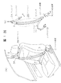
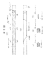
以下図面を参照して先願のエアベルト装置について説明する。第1図(a)は先願のエアベルト装置を備えた車両内部の斜視図、第1図(b)はこのエアベルト装置を示す斜視図である。第2図(a)はショルダーベルトとラップベルトとの連結部付近の平面図、第2図(b)は袋状ベルトの平面図、第2図(c),(d),(e)はそれぞれ第2図(a)のC−C線、D−D線、E−E線に沿う断面図である。第3図(a)はエアベルトが膨張した状態におけるショルダーベルトの平面図、第3図(b)は膨張した状態の袋状ベルトの平面図、第3図(c)及び(d)は第3図(a)のC−C線、D−D線に沿う断面図である。第4図はエアベルトのカバーの編み方の説明図である。
【0004】
このエアベルト装置1は、乗員の右側から左側へ斜めに延設されるショルダーベルト2と、乗員の右側から左側へ延設されるラップベルト3と、車体床部等に配設されたバックル装置4と、ベルト装着時にバックル装置4に挿入係止されるタング5と、ショルダーベルト2を案内する中間ガイド6とを備えている。
【0005】
ショルダーベルト2は、従来の一般的なシートベルトと同様のノーマルベルトで構成されたウェビング2Aと、このウェビング2Aの一端に連結されたエアベルト2Bとから構成されている。ウェビング2Aは中間ガイド6に摺動自在に案内掛通されている。ウェビング2Aの他端は、車体に固定された緊急時ロック機構付きシートベルトリトラクタ(ELR)7に連結されている。このシートベルトリトラクタ7にウェビング2Aは巻き取り可能とされている。
【0006】
エアベルト2Bは乗員が当接する部分に位置するようになっており、ウェビング2Aとの連結端部と反対側の端部がタング5に連結されている。
【0007】
ラップベルト3は、一般的なシートベルトと同様のノーマルベルトにより形成され、その一端がタング5に連結されているとともに、他端が車体に固定されたシートベルトリトラクタ(ELR)8に連結されている。更にバックル装置4には、車両衝突時等の緊急必要時に作動して高圧のガスを発生するガス発生装置9が連結されている。
【0008】
タング5及びバックル装置4には、ガス発生装置9からのガスをエアベルト2Bに導くための通路が設けられている。
【0009】
第2図及び第3図に示される通り、エアベルト2Bは、袋状ベルト10と、該袋状ベルト10を囲んでいる筒状のニットカバー12とを備えている。袋状ベルト10は、シートに座った乗員の胸から腹にかけた部分が広がった形状を有しており、第2図に示すように、この広がった部分を折り畳むことにより長い帯状とされる。なお、11は袋状ベルト10の縫目である。
【0010】
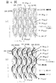
ニットカバー12は幅方向には柔軟に伸縮するが、長手方向には殆ど伸長しない構成のものとなっている。第4図(a),(b)はそれぞれこのニットカバーの編み方を示すものである。
【0011】
第4図(a)は編み糸20よりなる通常のたて編み物であり、複数本の編み糸20(20A〜20D)がループRをつくっている。各ループRは図の上から下に向って左方及び右方に交互に配置されている。各ループRの先端側(例えばループRB2の先端側)は隣接する編み糸のループの付け根部分(例えばループRA1の付け根部分)に巻き付き、基端側には隣接する編み糸のループの先端側(例えばループRA3の先端側)が巻き付いている。従って、図の上下方向においてはループRが連続して配置され、上下方向に左側の編み糸のループ、右側の編み糸のループが交互に配列されている。即ち、上からループRA1,RB2,RA3の順で並んでいる。
【0012】
第4図(b)は編み糸20に挿入糸30を入れることにより強度を高め且つ薄くしうるようにしたものである。この挿入糸30は、この上下方向に連なるループの列に沿って且つ編み糸20同士との交点を編み物の表側から裏側及び裏側から表側へ交互に通り抜けるように編み込まれている。図示の通り、この挿入糸30は編みの1列の縦列に絡んでいる。
【0013】
このエアベルト2Bとラップベルト3はタングに接合されている。ニットカバー12はウェビング2Aとタング5の双方に接合されており、エアベルトに加えられる引張負荷を負担するよう構成されている。
【0014】
バックル装置4にタング5を装着した状態でガス発生装置9が作動すると、エアベルト2Bが膨張する。この際、ニットカバー12のエアベルト2B長手方向の長さが短くなり、エアベルト2Bが乗員に密着し、乗員をきわめて確実に保護することが可能となる。
【0015】
第5図は、第4図(b)に示す挿入糸30を用いたたて編み物よりなるニットカバー12がエアベルト2B(袋状ベルト10)の膨張時にその長手方向の長さが短かくなる状況を示している。上記の通り、このニットカバー12は加熱延伸加工が施されることによりベルト長手方向へは殆ど伸びないものとなっている。袋状ベルト10が膨らんだときにニットカバー12の編目が横方向に広がり、その結果としてニットカバー12が長手方向に縮み、エアベルト2Bの長手方向の長さが短くなる。
【0016】
かかるエアベルト装置にあっては、ガス発生器が作動してエアベルトが膨張した場合、カバーも膨張する。このカバーはエアベルト長手方向には殆ど伸長しないため、エアベルト膨張時に長さが短くなる。このように、エアベルトの長さが短くなる結果、エアベルトが強く乗員にフィットするようになる。このため乗員を確実に保護することができる。
【0017】
【発明が解決しようとする課題】
本発明は、上記の如き挿入糸を有したエアベルトカバー用たて編み物のラン(伝線)の耐性を高めることを目的とする。また、本発明は、このエアベルトカバー用たて編み物よりなるエアベルトカバーと、このエアベルトカバーを備えたエアベルト装置を提供することを目的とする。
【0018】
【課題を解決するための手段】
本発明のエアベルトカバー用たて編み物は、膨張可能なエアベルトを構成する、帯状となるように折り畳まれた袋状ベルトを被覆するためのエアベルトカバー用のたて編み物であって、編み糸とこの編み糸に挿入された挿入糸とを備えるエアベルトカバー用たて編み物において、該挿入糸を編みの縦列に対し3列以上絡ませたことを特徴とするものである。
【0019】
かかる本発明のエアベルトカバー用たて編み物では、挿入糸を3個以上の編み縦列に対し絡ませたことにより、ランに対する耐性が著しく向上する。
本発明のエアベルトカバーは、かかる本発明のエアベルトカバー用たて編み物よりなるものである。また、本発明のエアベルト装置は、このエアベルトカバーを備えてなるものである。
【0020】
【発明の実施の形態】
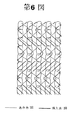
以下に第6,7図を参照して本発明の実施の形態を説明する。
【0021】
本発明のエアベルトカバー用たて編み物は、通常のたて編み物の編み糸20に挿入糸30を入れたものであり、基本編み地に対して、1本の挿入糸30が各々上下方向に連なるループの3列の縦列に絡むように編み込まれている。
【0022】
第6図では縦列の鎖編みが縦列方向には連続していない。即ち、編み糸は1個の鎖編み(ループ)を形成すると直ちに隣りの縦列にシフトしてその縦列で1個の鎖編み(ループ)を形成し次いでまた元の縦列に戻り、これを繰り返している。
【0023】
第6図の編み組織において挿入糸は3縦列に渡って絡んでいる。例えば、左、中、右の3縦列において挿入糸は左→中→右→中→左中→右→中(以下、繰り返し)の順に3個の縦列に絡んでいる。
【0024】
このように挿入糸を3縦列に絡ませることにより、ランが防止される。なお、第7図は挿入糸が無い比較例におけるランの発生状況を示す模式図である。(a)図のように糸切れが起り、ループの絡みが1ヶ所において無くなると、(b)図、(c)図のように次々とループが外れ、裂目が広がる。挿入糸を設けることによりこの裂け目の拡大が防止されるのであるが、挿入糸を3列以上の縦列に絡ませることにより、この裂目の拡張がきわめて確実に防止されるようになる。
【0025】
本発明では、挿入糸30は3〜6列の縦列に絡まっていることが好ましい。
【0026】
なお、本発明においては、編み糸及び挿入糸(以下、これらを「構成糸」と総称する。)は、ポリアミド又はポリエステル糸等の熱可塑性合成フィラメント糸よりなり、原糸強度8.0g/d以上のものが好ましい。
【0027】
また、本発明においては、構成糸は、5〜10dの細いフィラメントで構成されるのが好ましく、特に好ましくは、挿入糸としては、5〜10dのフィラメント100〜300本よりなる1000〜3000dの糸条を2本引き揃えて3000d以下としたものを用い、編み糸としては、5〜10dのフィラメント30〜300本よりなる250〜1500dの糸条を上記挿入糸のデニール数よりも小さくしたものを用いるのが好ましい。
【0028】
また、本発明のエアベルトカバー用たて編み物は、ヒートセットによる加熱延伸加工を施すことで、伸度設定や幅調整を行うのが好ましい。
【0029】
なお、本発明においては、要求される引張強度特性から挿入糸の本数を決定するのが好ましい。
【0030】
本発明のエアベルトカバー用たて編み物は、上記構成により、好ましくは、厚さ1.0〜2.0mmで、100kPa時の横方向(ウェール)の伸びによる長さ方向(コート)に発生する張力(以下、この張力を「長さ規制張力」と称す。)が200〜600kgfとなるように製作される。
【0031】
【発明の効果】
以上の通り、本発明によれば、エアベルト装置のニットカバーとしての優れた耐ラン性を具備したエアベルトカバー用たて編み物と、このエアベルトカバー用たて編み物よりなるエアベルトカバーと、このエアベルトカバーを備えてなるエアベルト装置とが提供される。
【図面の簡単な説明】
【図1】 先願に係るエアベルト装置を備えた座席の斜視図と、該エアベルト装置の斜視図である。
【図2】 エアベルトの構成図である。
【図3】 エアベルトの膨張時の構成図である。
【図4】 ニットカバーの編み方の説明図である。
【図5】 エアベルトの平常時と膨張時の状態を対比して示す説明図である。
【図6】 実施の形態に係るエアベルトカバー用たて編み物の構成図(編み組織図)である。
【図7】 ランの発生状況の説明図である。
【符号の説明】
1 エアベルト装置
2 ショルダーベルト
2A ウェビング
2B エアベルト
3 ラップベルト
4 バックル装置
5 タング
6 中間ガイド
7,8 シートベルトリトラクタ
9 ガス発生装置
10 袋状ベルト
12 ニットカバー
20 編み糸
30 挿入糸[0001]
BACKGROUND OF THE INVENTION
The present invention relates to a bag of an air belt apparatus in which a part of a seat belt is a bag-like belt and the bag-like belt is inflated by gas from a gas generator in order to protect a vehicle occupant in a vehicle collision or the like. The present invention relates to a warp knitted fabric for an air belt cover for covering a belt. The present invention also relates to an air belt cover and an air belt device using the warp knitted fabric for the air belt cover.
[0002]
[Prior art and prior art]
As this type of inflatable belt device, the present applicant has firstly provided an inflatable inflatable belt and a gas generator for inflating by supplying gas into the inflatable belt, and the inflatable belt is formed in a belt shape. In an inflatable belt device comprising a folded bag-shaped belt and a cover surrounding the bag-shaped belt, the cover hardly extends in the longitudinal direction of the air belt, extends in the inflating direction of the air belt, and An air belt device has been proposed in which the length in the longitudinal direction of the air belt is reduced by extending in the air belt expansion direction (Japanese Patent Application No. 9-236903, hereinafter referred to as “prior application”).
[0003]
The prior art air belt apparatus will be described below with reference to the drawings. FIG. 1 (a) is a perspective view of the interior of a vehicle provided with the prior-art air belt device, and FIG. 1 (b) is a perspective view showing the air belt device. 2 (a) is a plan view of the vicinity of the connecting portion between the shoulder belt and the lap belt, FIG. 2 (b) is a plan view of the bag-like belt, and FIGS. 2 (c), (d) and (e) are It is sectional drawing which follows the CC line, DD line, and EE line of Fig.2 (a), respectively. 3 (a) is a plan view of the shoulder belt in an inflated state, FIG. 3 (b) is a plan view of the inflated bag-like belt, and FIGS. 3 (c) and 3 (d) are third views. It is sectional drawing which follows the CC line and DD line of figure (a). FIG. 4 is an explanatory view of a method of knitting the cover of the air belt.
[0004]
The air belt device 1 includes a shoulder belt 2 that extends obliquely from the right side to the left side of the occupant, a lap belt 3 that extends from the right side to the left side of the occupant, and a buckle device 4 that is disposed on a vehicle body floor. And a tongue 5 inserted and locked to the buckle device 4 when the belt is mounted, and an intermediate guide 6 for guiding the shoulder belt 2.
[0005]
The shoulder belt 2 includes a
[0006]
The air belt 2 </ b> B is positioned at a portion where the occupant abuts, and the end opposite to the connection end with the webbing 2 </ b> A is connected to the tongue 5.
[0007]
The lap belt 3 is formed of a normal belt similar to a general seat belt, one end of which is connected to the tongue 5 and the other end is connected to a seat belt retractor (ELR) 8 fixed to the vehicle body. Yes. Further, the buckle device 4 is connected to a gas generator 9 that is activated in the event of an emergency such as a vehicle collision and generates high-pressure gas.
[0008]
The tongue 5 and the buckle device 4 are provided with a passage for guiding the gas from the gas generator 9 to the air belt 2B.
[0009]
As shown in FIGS. 2 and 3, the air belt 2 </ b> B includes a bag-like belt 10 and a cylindrical knit cover 12 surrounding the bag-like belt 10. The bag-shaped belt 10 has a shape in which a portion from the chest of an occupant sitting on the seat to the abdomen is widened, and as shown in FIG. 2, the widened portion is folded into a long band shape. Reference numeral 11 denotes a seam of the bag-like belt 10.
[0010]
The knit cover 12 is configured to flexibly expand and contract in the width direction but hardly extend in the longitudinal direction. FIGS. 4 (a) and 4 (b) show how to knit the knit cover.
[0011]
FIG. 4 (a) shows a normal warp knitting made of the
[0012]
FIG. 4B shows that the insertion thread 30 is inserted into the knitting
[0013]
The air belt 2B and the lap belt 3 are joined to the tongue. The knit cover 12 is joined to both the
[0014]
When the gas generator 9 is activated with the tongue 5 attached to the buckle device 4, the air belt 2B expands. At this time, the length of the knit cover 12 in the longitudinal direction of the air belt 2B is shortened, the air belt 2B comes into close contact with the occupant, and the occupant can be protected extremely reliably.
[0015]
FIG. 5 shows a situation in which the longitudinal length of the knit cover 12 made of warp knitting using the insertion thread 30 shown in FIG. 4 (b) becomes short when the air belt 2B (bag-like belt 10) is inflated. Is shown. As described above, the knit cover 12 is hardly stretched in the longitudinal direction of the belt due to the heat stretching process. When the bag-shaped belt 10 swells, the stitches of the knit cover 12 spread in the lateral direction, and as a result, the knit cover 12 contracts in the longitudinal direction, and the length of the air belt 2B in the longitudinal direction becomes shorter.
[0016]
In such an air belt device, when the gas generator is activated and the air belt is expanded, the cover is also expanded. Since this cover hardly extends in the longitudinal direction of the air belt, the length is shortened when the air belt is expanded. As described above, as a result of the shortening of the length of the air belt, the air belt strongly fits the occupant. For this reason, a passenger | crew can be protected reliably.
[0017]
[Problems to be solved by the invention]
It is an object of the present invention to increase the resistance of a warp knitted run (wire) for an air belt cover having the insertion yarn as described above. Another object of the present invention is to provide an air belt cover made of a warp knitted fabric for the air belt cover and an air belt device provided with the air belt cover.
[0018]
[Means for Solving the Problems]
A warp knitted fabric for an air belt cover according to the present invention is a warp knitted fabric for an air belt cover for covering a bag-shaped belt folded to form a belt, which constitutes an inflatable air belt. A warp knitted fabric for an air belt cover provided with an insertion yarn inserted into a knitting yarn, wherein the insertion yarn is entangled in three or more rows with respect to a knitting longitudinal column.
[0019]
In the warp knitted fabric for the air belt cover of the present invention, the resistance to the run is remarkably improved by entangled the insertion yarn with three or more knitting columns.
The air belt cover of the present invention is made of the warp knitted fabric for the air belt cover of the present invention. The inflatable belt device of the present invention comprises this inflatable belt cover.
[0020]
DETAILED DESCRIPTION OF THE INVENTION
The embodiment of the present invention will be described below with reference to FIGS.
[0021]
The warp knitted fabric for the air belt cover of the present invention is obtained by inserting an insertion yarn 30 into a normal
[0022]
In FIG. 6, the chain stitches in the column are not continuous in the column direction. That is, the knitting yarn immediately shifts to the adjacent column as soon as one chain knitting (loop) is formed, forms one chain knitting (loop) in that column, and then returns to the original column, and this is repeated. Yes.
[0023]
In the knitting structure of FIG. 6, the insertion yarn is entangled in three columns. For example, in three columns of left, middle, and right, the insertion thread is entangled in three columns in the order of left → middle → right → middle → left middle → right → middle (hereinafter repeated).
[0024]
Thus, the run is prevented by entwining the insertion yarns in three columns. FIG. 7 is a schematic diagram showing a run occurrence state in a comparative example having no insertion thread. (A) When the thread breakage occurs as shown in the figure and the loop entanglement disappears at one place, the loops come off one after another as shown in FIGS. By providing the insertion thread, the expansion of the tear is prevented, but when the insertion thread is entangled in three or more columns, the expansion of the tear is surely prevented.
[0025]
In the present invention, it is preferable that the insertion yarn 30 is entangled in 3 to 6 columns.
[0026]
In the present invention, the knitting yarn and the insertion yarn (hereinafter collectively referred to as “component yarns”) are made of thermoplastic synthetic filament yarn such as polyamide or polyester yarn, and the raw yarn strength is 8.0 g / d. The above is preferable.
[0027]
In the present invention, the constituent yarn is preferably composed of a thin filament of 5 to 10d, and particularly preferably, the insertion yarn is a 1000 to 3000d yarn composed of 100 to 300 filaments of 5 to 10d. Using two yarns that are aligned to 3000 d or less, the knitting yarn is a yarn of 250 to 1500 d consisting of 30 to 300 filaments of 5 to 10 d and smaller than the denier number of the insertion yarn. It is preferable to use it.
[0028]
Moreover, it is preferable that the warp knitted fabric for an air belt cover of the present invention performs elongation setting and width adjustment by performing heat stretching processing by heat setting.
[0029]
In the present invention, it is preferable to determine the number of inserted yarns from the required tensile strength characteristics.
[0030]
The warp knitted fabric for an air belt cover of the present invention is preferably 1.0 to 2.0 mm in thickness, and has a tension generated in the length direction (coating) due to elongation in the lateral direction (wel) at 100 kPa. (Hereinafter, this tension is referred to as “length regulation tension”.) Is manufactured to be 200 to 600 kgf.
[0031]
【The invention's effect】
As described above, according to the present invention, a warp knitted fabric for an air belt cover having excellent run resistance as a knit cover of an air belt device, an air belt cover made of a warp knitted fabric for the air belt cover, and the air belt cover An inflatable belt device is provided.
[Brief description of the drawings]
FIG. 1 is a perspective view of a seat provided with an air belt device according to a prior application, and a perspective view of the air belt device.
FIG. 2 is a configuration diagram of an air belt.
FIG. 3 is a configuration diagram when the air belt is inflated.
FIG. 4 is an explanatory diagram of how to knit a knit cover.
FIG. 5 is an explanatory view showing a comparison between a normal state of an air belt and a state during expansion.
FIG. 6 is a configuration diagram (knitting structure diagram) of a warp knitted fabric for an air belt cover according to an embodiment.
FIG. 7 is an explanatory diagram of a run occurrence state.
[Explanation of symbols]
DESCRIPTION OF SYMBOLS 1 Air belt apparatus 2
Claims (4)
該挿入糸を編みの縦列に対し3列以上絡ませたことを特徴とするエアベルトカバー用たて編み物。A warp knitted fabric for an air belt cover for covering a bag-shaped belt folded to form an inflatable air belt, comprising a knitting yarn and an insertion yarn inserted into the knitting yarn In warp knitting for air belt cover,
A warp knitted fabric for an air belt cover, wherein the insertion yarn is entangled in three or more rows with respect to a knitting vertical row.
Priority Applications (3)
| Application Number | Priority Date | Filing Date | Title |
|---|---|---|---|
| JP00669299A JP3757656B2 (en) | 1999-01-13 | 1999-01-13 | Warp knitting for air belt cover, air belt cover and air belt device |
| JP27685599A JP4135273B2 (en) | 1999-01-13 | 1999-09-29 | Warp knitting for air belt cover and air belt device |
| US09/482,118 US6370924B1 (en) | 1999-01-13 | 2000-01-13 | Warp-knitted fabric for inflatable belt cover |
Applications Claiming Priority (1)
| Application Number | Priority Date | Filing Date | Title |
|---|---|---|---|
| JP00669299A JP3757656B2 (en) | 1999-01-13 | 1999-01-13 | Warp knitting for air belt cover, air belt cover and air belt device |
Related Child Applications (1)
| Application Number | Title | Priority Date | Filing Date |
|---|---|---|---|
| JP27685599A Division JP4135273B2 (en) | 1999-01-13 | 1999-09-29 | Warp knitting for air belt cover and air belt device |
Publications (3)
| Publication Number | Publication Date |
|---|---|
| JP2000212863A JP2000212863A (en) | 2000-08-02 |
| JP2000212863A5 JP2000212863A5 (en) | 2004-12-16 |
| JP3757656B2 true JP3757656B2 (en) | 2006-03-22 |
Family
ID=11645408
Family Applications (1)
| Application Number | Title | Priority Date | Filing Date |
|---|---|---|---|
| JP00669299A Expired - Lifetime JP3757656B2 (en) | 1999-01-13 | 1999-01-13 | Warp knitting for air belt cover, air belt cover and air belt device |
Country Status (1)
| Country | Link |
|---|---|
| JP (1) | JP3757656B2 (en) |
Cited By (1)
| Publication number | Priority date | Publication date | Assignee | Title |
|---|---|---|---|---|
| CN105292046A (en) * | 2015-10-22 | 2016-02-03 | 成都易默生汽车技术有限公司 | Use method of air bag type safety belt structure |
Families Citing this family (2)
| Publication number | Priority date | Publication date | Assignee | Title |
|---|---|---|---|---|
| JP2008302905A (en) | 2007-06-11 | 2008-12-18 | Takata Corp | Elastic webbing, air belt, and air belt device |
| JP5803595B2 (en) | 2011-11-15 | 2015-11-04 | タカタ株式会社 | Air belt and air belt device |
-
1999
- 1999-01-13 JP JP00669299A patent/JP3757656B2/en not_active Expired - Lifetime
Cited By (1)
| Publication number | Priority date | Publication date | Assignee | Title |
|---|---|---|---|---|
| CN105292046A (en) * | 2015-10-22 | 2016-02-03 | 成都易默生汽车技术有限公司 | Use method of air bag type safety belt structure |
Also Published As
| Publication number | Publication date |
|---|---|
| JP2000212863A (en) | 2000-08-02 |
Similar Documents
| Publication | Publication Date | Title |
|---|---|---|
| US6685220B2 (en) | Airbelt and airbelt apparatus | |
| US9027961B2 (en) | Air belt and air belt apparatus | |
| JP3945100B2 (en) | Air belt and air belt device | |
| US5385367A (en) | Inflatable seatbelt system | |
| US6641165B2 (en) | Air belt apparatus | |
| JP2562285B2 (en) | Safety belt with tearable seams | |
| US6837079B1 (en) | Warp knitted fabric for air belt cover | |
| JP4135273B2 (en) | Warp knitting for air belt cover and air belt device | |
| JP3888009B2 (en) | Air belt and air belt device | |
| JP3757656B2 (en) | Warp knitting for air belt cover, air belt cover and air belt device | |
| JP3767173B2 (en) | Air belt bag | |
| US6375218B2 (en) | Airbelt and airbelt apparatus | |
| JP3849306B2 (en) | Warp knitting, air belt and air belt device for air belt cover | |
| JP2000212864A5 (en) | ||
| JP2000212863A5 (en) | ||
| CN112601681B (en) | Belt strap for a safety belt device of a motor vehicle | |
| JP3899740B2 (en) | Air belt and air belt device | |
| JPH11348725A (en) | Wale knitting for air belt cover | |
| JP2006001548A (en) | Air belt |
Legal Events
| Date | Code | Title | Description |
|---|---|---|---|
| A521 | Written amendment |
Free format text: JAPANESE INTERMEDIATE CODE: A523 Effective date: 20040113 |
|
| A621 | Written request for application examination |
Free format text: JAPANESE INTERMEDIATE CODE: A621 Effective date: 20040113 |
|
| A977 | Report on retrieval |
Free format text: JAPANESE INTERMEDIATE CODE: A971007 Effective date: 20050830 |
|
| A131 | Notification of reasons for refusal |
Free format text: JAPANESE INTERMEDIATE CODE: A131 Effective date: 20050913 |
|
| A521 | Written amendment |
Free format text: JAPANESE INTERMEDIATE CODE: A523 Effective date: 20051102 |
|
| TRDD | Decision of grant or rejection written | ||
| A01 | Written decision to grant a patent or to grant a registration (utility model) |
Free format text: JAPANESE INTERMEDIATE CODE: A01 Effective date: 20051206 |
|
| A61 | First payment of annual fees (during grant procedure) |
Free format text: JAPANESE INTERMEDIATE CODE: A61 Effective date: 20051219 |
|
| R150 | Certificate of patent or registration of utility model |
Free format text: JAPANESE INTERMEDIATE CODE: R150 |
|
| S111 | Request for change of ownership or part of ownership |
Free format text: JAPANESE INTERMEDIATE CODE: R313111 |
|
| R350 | Written notification of registration of transfer |
Free format text: JAPANESE INTERMEDIATE CODE: R350 |
|
| FPAY | Renewal fee payment (event date is renewal date of database) |
Free format text: PAYMENT UNTIL: 20100113 Year of fee payment: 4 |
|
| FPAY | Renewal fee payment (event date is renewal date of database) |
Free format text: PAYMENT UNTIL: 20100113 Year of fee payment: 4 |
|
| S531 | Written request for registration of change of domicile |
Free format text: JAPANESE INTERMEDIATE CODE: R313531 |
|
| FPAY | Renewal fee payment (event date is renewal date of database) |
Free format text: PAYMENT UNTIL: 20100113 Year of fee payment: 4 |
|
| R350 | Written notification of registration of transfer |
Free format text: JAPANESE INTERMEDIATE CODE: R350 |
|
| FPAY | Renewal fee payment (event date is renewal date of database) |
Free format text: PAYMENT UNTIL: 20110113 Year of fee payment: 5 |
|
| FPAY | Renewal fee payment (event date is renewal date of database) |
Free format text: PAYMENT UNTIL: 20110113 Year of fee payment: 5 |
|
| FPAY | Renewal fee payment (event date is renewal date of database) |
Free format text: PAYMENT UNTIL: 20120113 Year of fee payment: 6 |
|
| FPAY | Renewal fee payment (event date is renewal date of database) |
Free format text: PAYMENT UNTIL: 20120113 Year of fee payment: 6 |
|
| FPAY | Renewal fee payment (event date is renewal date of database) |
Free format text: PAYMENT UNTIL: 20130113 Year of fee payment: 7 |
|
| FPAY | Renewal fee payment (event date is renewal date of database) |
Free format text: PAYMENT UNTIL: 20130113 Year of fee payment: 7 |
|
| FPAY | Renewal fee payment (event date is renewal date of database) |
Free format text: PAYMENT UNTIL: 20140113 Year of fee payment: 8 |
|
| R250 | Receipt of annual fees |
Free format text: JAPANESE INTERMEDIATE CODE: R250 |
|
| R250 | Receipt of annual fees |
Free format text: JAPANESE INTERMEDIATE CODE: R250 |
|
| R250 | Receipt of annual fees |
Free format text: JAPANESE INTERMEDIATE CODE: R250 |
|
| R250 | Receipt of annual fees |
Free format text: JAPANESE INTERMEDIATE CODE: R250 |
|
| R250 | Receipt of annual fees |
Free format text: JAPANESE INTERMEDIATE CODE: R250 |
|
| S111 | Request for change of ownership or part of ownership |
Free format text: JAPANESE INTERMEDIATE CODE: R313113 |
|
| S343 | Written request for registration of root pledge or change of root pledge |
Free format text: JAPANESE INTERMEDIATE CODE: R316354 |
|
| SZ02 | Written request for trust registration |
Free format text: JAPANESE INTERMEDIATE CODE: R316Z02 |
|
| S343 | Written request for registration of root pledge or change of root pledge |
Free format text: JAPANESE INTERMEDIATE CODE: R316354 |
|
| R350 | Written notification of registration of transfer |
Free format text: JAPANESE INTERMEDIATE CODE: R350 |
|
| S343 | Written request for registration of root pledge or change of root pledge |
Free format text: JAPANESE INTERMEDIATE CODE: R316354 |
|
| SZ02 | Written request for trust registration |
Free format text: JAPANESE INTERMEDIATE CODE: R316Z02 |
|
| R350 | Written notification of registration of transfer |
Free format text: JAPANESE INTERMEDIATE CODE: R350 |
|
| EXPY | Cancellation because of completion of term |