JP3756522B2 - Flexible tissue excision element for creating long lesions - Google Patents
Flexible tissue excision element for creating long lesions Download PDFInfo
- Publication number
- JP3756522B2 JP3756522B2 JP51898897A JP51898897A JP3756522B2 JP 3756522 B2 JP3756522 B2 JP 3756522B2 JP 51898897 A JP51898897 A JP 51898897A JP 51898897 A JP51898897 A JP 51898897A JP 3756522 B2 JP3756522 B2 JP 3756522B2
- Authority
- JP
- Japan
- Prior art keywords
- wire
- electrode
- edge portion
- elongated
- windings
- Prior art date
- Legal status (The legal status is an assumption and is not a legal conclusion. Google has not performed a legal analysis and makes no representation as to the accuracy of the status listed.)
- Expired - Lifetime
Links
Images


Classifications
-
- A—HUMAN NECESSITIES
- A61—MEDICAL OR VETERINARY SCIENCE; HYGIENE
- A61B—DIAGNOSIS; SURGERY; IDENTIFICATION
- A61B18/00—Surgical instruments, devices or methods for transferring non-mechanical forms of energy to or from the body
- A61B18/04—Surgical instruments, devices or methods for transferring non-mechanical forms of energy to or from the body by heating
- A61B18/12—Surgical instruments, devices or methods for transferring non-mechanical forms of energy to or from the body by heating by passing a current through the tissue to be heated, e.g. high-frequency current
- A61B18/14—Probes or electrodes therefor
- A61B18/1492—Probes or electrodes therefor having a flexible, catheter-like structure, e.g. for heart ablation
-
- A—HUMAN NECESSITIES
- A61—MEDICAL OR VETERINARY SCIENCE; HYGIENE
- A61B—DIAGNOSIS; SURGERY; IDENTIFICATION
- A61B5/00—Measuring for diagnostic purposes; Identification of persons
- A61B5/24—Detecting, measuring or recording bioelectric or biomagnetic signals of the body or parts thereof
- A61B5/25—Bioelectric electrodes therefor
- A61B5/279—Bioelectric electrodes therefor specially adapted for particular uses
- A61B5/28—Bioelectric electrodes therefor specially adapted for particular uses for electrocardiography [ECG]
- A61B5/283—Invasive
- A61B5/287—Holders for multiple electrodes, e.g. electrode catheters for electrophysiological study [EPS]
-
- A—HUMAN NECESSITIES
- A61—MEDICAL OR VETERINARY SCIENCE; HYGIENE
- A61B—DIAGNOSIS; SURGERY; IDENTIFICATION
- A61B5/00—Measuring for diagnostic purposes; Identification of persons
- A61B5/68—Arrangements of detecting, measuring or recording means, e.g. sensors, in relation to patient
- A61B5/6846—Arrangements of detecting, measuring or recording means, e.g. sensors, in relation to patient specially adapted to be brought in contact with an internal body part, i.e. invasive
- A61B5/6847—Arrangements of detecting, measuring or recording means, e.g. sensors, in relation to patient specially adapted to be brought in contact with an internal body part, i.e. invasive mounted on an invasive device
- A61B5/6852—Catheters
- A61B5/6858—Catheters with a distal basket, e.g. expandable basket
-
- A—HUMAN NECESSITIES
- A61—MEDICAL OR VETERINARY SCIENCE; HYGIENE
- A61N—ELECTROTHERAPY; MAGNETOTHERAPY; RADIATION THERAPY; ULTRASOUND THERAPY
- A61N1/00—Electrotherapy; Circuits therefor
- A61N1/02—Details
- A61N1/04—Electrodes
- A61N1/05—Electrodes for implantation or insertion into the body, e.g. heart electrode
- A61N1/056—Transvascular endocardial electrode systems
-
- A—HUMAN NECESSITIES
- A61—MEDICAL OR VETERINARY SCIENCE; HYGIENE
- A61N—ELECTROTHERAPY; MAGNETOTHERAPY; RADIATION THERAPY; ULTRASOUND THERAPY
- A61N1/00—Electrotherapy; Circuits therefor
- A61N1/02—Details
- A61N1/04—Electrodes
- A61N1/06—Electrodes for high-frequency therapy
-
- A—HUMAN NECESSITIES
- A61—MEDICAL OR VETERINARY SCIENCE; HYGIENE
- A61N—ELECTROTHERAPY; MAGNETOTHERAPY; RADIATION THERAPY; ULTRASOUND THERAPY
- A61N1/00—Electrotherapy; Circuits therefor
- A61N1/40—Applying electric fields by inductive or capacitive coupling ; Applying radio-frequency signals
-
- G—PHYSICS
- G01—MEASURING; TESTING
- G01K—MEASURING TEMPERATURE; MEASURING QUANTITY OF HEAT; THERMALLY-SENSITIVE ELEMENTS NOT OTHERWISE PROVIDED FOR
- G01K1/00—Details of thermometers not specially adapted for particular types of thermometer
- G01K1/02—Means for indicating or recording specially adapted for thermometers
- G01K1/026—Means for indicating or recording specially adapted for thermometers arrangements for monitoring a plurality of temperatures, e.g. by multiplexing
-
- G—PHYSICS
- G01—MEASURING; TESTING
- G01K—MEASURING TEMPERATURE; MEASURING QUANTITY OF HEAT; THERMALLY-SENSITIVE ELEMENTS NOT OTHERWISE PROVIDED FOR
- G01K3/00—Thermometers giving results other than momentary value of temperature
- G01K3/08—Thermometers giving results other than momentary value of temperature giving differences of values; giving differentiated values
- G01K3/14—Thermometers giving results other than momentary value of temperature giving differences of values; giving differentiated values in respect of space
-
- A—HUMAN NECESSITIES
- A61—MEDICAL OR VETERINARY SCIENCE; HYGIENE
- A61B—DIAGNOSIS; SURGERY; IDENTIFICATION
- A61B17/00—Surgical instruments, devices or methods, e.g. tourniquets
- A61B2017/00017—Electrical control of surgical instruments
- A61B2017/00022—Sensing or detecting at the treatment site
- A61B2017/00084—Temperature
- A61B2017/00088—Temperature using thermistors
-
- A—HUMAN NECESSITIES
- A61—MEDICAL OR VETERINARY SCIENCE; HYGIENE
- A61B—DIAGNOSIS; SURGERY; IDENTIFICATION
- A61B17/00—Surgical instruments, devices or methods, e.g. tourniquets
- A61B2017/00017—Electrical control of surgical instruments
- A61B2017/00022—Sensing or detecting at the treatment site
- A61B2017/00084—Temperature
- A61B2017/00092—Temperature using thermocouples
-
- A—HUMAN NECESSITIES
- A61—MEDICAL OR VETERINARY SCIENCE; HYGIENE
- A61B—DIAGNOSIS; SURGERY; IDENTIFICATION
- A61B17/00—Surgical instruments, devices or methods, e.g. tourniquets
- A61B2017/00831—Material properties
- A61B2017/0088—Material properties ceramic
-
- A—HUMAN NECESSITIES
- A61—MEDICAL OR VETERINARY SCIENCE; HYGIENE
- A61B—DIAGNOSIS; SURGERY; IDENTIFICATION
- A61B18/00—Surgical instruments, devices or methods for transferring non-mechanical forms of energy to or from the body
- A61B2018/00053—Mechanical features of the instrument of device
- A61B2018/00059—Material properties
- A61B2018/00071—Electrical conductivity
- A61B2018/00083—Electrical conductivity low, i.e. electrically insulating
-
- A—HUMAN NECESSITIES
- A61—MEDICAL OR VETERINARY SCIENCE; HYGIENE
- A61B—DIAGNOSIS; SURGERY; IDENTIFICATION
- A61B18/00—Surgical instruments, devices or methods for transferring non-mechanical forms of energy to or from the body
- A61B2018/00053—Mechanical features of the instrument of device
- A61B2018/00107—Coatings on the energy applicator
- A61B2018/00148—Coatings on the energy applicator with metal
-
- A—HUMAN NECESSITIES
- A61—MEDICAL OR VETERINARY SCIENCE; HYGIENE
- A61B—DIAGNOSIS; SURGERY; IDENTIFICATION
- A61B18/00—Surgical instruments, devices or methods for transferring non-mechanical forms of energy to or from the body
- A61B2018/00053—Mechanical features of the instrument of device
- A61B2018/0016—Energy applicators arranged in a two- or three dimensional array
-
- A—HUMAN NECESSITIES
- A61—MEDICAL OR VETERINARY SCIENCE; HYGIENE
- A61B—DIAGNOSIS; SURGERY; IDENTIFICATION
- A61B18/00—Surgical instruments, devices or methods for transferring non-mechanical forms of energy to or from the body
- A61B2018/00636—Sensing and controlling the application of energy
- A61B2018/00773—Sensed parameters
- A61B2018/00791—Temperature
-
- A—HUMAN NECESSITIES
- A61—MEDICAL OR VETERINARY SCIENCE; HYGIENE
- A61B—DIAGNOSIS; SURGERY; IDENTIFICATION
- A61B18/00—Surgical instruments, devices or methods for transferring non-mechanical forms of energy to or from the body
- A61B18/04—Surgical instruments, devices or methods for transferring non-mechanical forms of energy to or from the body by heating
- A61B18/12—Surgical instruments, devices or methods for transferring non-mechanical forms of energy to or from the body by heating by passing a current through the tissue to be heated, e.g. high-frequency current
- A61B18/14—Probes or electrodes therefor
- A61B2018/1405—Electrodes having a specific shape
- A61B2018/1435—Spiral
Description
関連出願
この出願は、1994年8月8日に出願された、「真っ直ぐなまたは曲線の電極要素を用いる身体組織中に細長い損傷パターンを形成するシステムおよび方法」と題する、米国特許出願第08/287,192号の一部継続出願である。この出願はまた、1995年5月12日に出願された、「複数の温度感知要素を用いる組織切除を制御するためのシステムおよび方法」と題する米国特許出願第08/439,824号の一部継続出願である。
発明の分野
本発明は、心臓疾患の処置のために心筋組織を切除するシステムおよび方法に関する。
発明の背景
今日、医師は、医療手順においてカテーテルを使用し、身体の内部領域中への接近を得、標的組織領域を切除する。医師が、カテーテルを正確に配置し、かつ組織切除手順の間に身体内でそのエネルギー放出を制御し得ることが重要である。
例えば、電気生理学的治療では、切除を用いて心拍障害を処置する。
これらの治療の間、医師は、主要な静脈または動脈を通じて、処置されるべき心臓の内部領域中にカテーテルを操縦する。医師は、カテーテル上に保持される切除要素を、切除されるべき心臓組織の近くに配置する。医師は、切除要素からのエネルギーを向け、組織を切除し、かつ損傷を形成する。
電気生理学的治療では、異なる幾何学的形状を有する心臓組織中に損傷を提供し得る切除要素に対する増大する必要性が存在する。
例えば、心房線維攣縮の処置は、心臓組織において異なる曲線形状の長い損傷の形成を必要とすると考えられている。そのような長い損傷パターンは、心臓内に複数の切除領域を有する可撓性の切除要素の配置を必要とする。切除によるこれら損傷の形成は、手術の複雑な手順が現在提供する複雑な縫合パターンと同じ治療利点を侵襲的な開心手術なくして提供し得る。
別の例として、心房粗動および心室頻拍の処置は、心臓組織中に比較的大きなかつ深い損傷パターンの形成を必要とすると考えられている。単に「より大きな」電極を提供することは、この必要性を満足しない。大きな電極を保持するカテーテルは、心臓中に導入することが困難であり、かつ心臓組織と緊密に接触して配置することが困難である。しかし、可撓性の本体に沿って間隔を置いて離れた、分離された、複数の電極の間に、これら電極に必要なより大きな切除塊を分配することにより、これらの困難性は克服され得る。
より大きなおよび/またはより長い複数電極要素を用いて、切除プロセスのより正確な制御に対する要求が生じる。切除エネルギーの送達は、所望されない組織損傷および凝塊形成の発生を避けるように管理されなければならない。切除エネルギーの送達はまた、切除組織における熱スポットおよび/またはギャップを形成することなく、一様かつ連続的な損傷の形成を確実にするために、注意深く制御されなければならない。
発明の要旨
本発明は、身身体組織を切除するためのデバイスおよび方法を提供する。このデバイスおよび方法は、隣接する巻線(複数)において、支持体周囲にワイヤを巻き、1つ以上の細長い電極を形成する。連結部が、細長い電極による切除組織への伝達のために、ワイヤを、切除エネルギーの供給源に接続する。本発明によれば、隣接する巻線は、間隔を置いて離れて配置され、細長い電極に増加した可撓性を与える。
好ましい実施態様では、隣接巻線は、ワイヤの幅の少なくとも1/5だけ間隔を置いて離れている。好ましい実施例では、巻線は、ワイヤの幅の約1/2だけ間隔を置いて離れている。
好ましい実施態様では、細長い電極は、支持体に接合する少なくとも1つのエッジを有する。この実施態様では、隣接する巻線は、エッジにおけるよりエッジから離れると、さらに離れて間隔を置いて配置される。1つの実施例では、隣接する巻線間の間隔は、エッジから離れると変動する。別の実施例では、隣接巻線間の間隔は、エッジから離れてもほぼ均一である。
好ましい実施態様では、温度感知要素が、少なくとも1つのエッジの近傍にある電極により保持され、そこでは、隣接する巻線が一緒により近接しており、それを支持する。
好ましい実施態様では、連結部が、細長い電極による切除組織への伝達のために、ワイヤを、高周波切除エネルギーの供給源に接続する。
本発明の他の特徴および利点は、以下の明細書および図面、ならびに添付の請求項に呈示される。
【図面の簡単な説明】
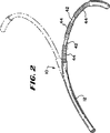
図1は、間隔を置いて離れたコイル電極のアレイを備える可撓性の切除要素を保持するプローブの図である;
図2は、図1に示されるプローブにより保持される、間隔を置いて離れたコイル電極のアレイの拡大図である;
図3は、図1に示されるプローブのハンドルの拡大図であり、一部を切り欠き、そして断面で、切除要素を曲げる操縦機構を示す;
図4は、切除要素を曲げるための操縦機構をさらに示す、切除要素の拡大側断面図である;
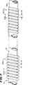
図5および6は、それぞれ、コイル電極を備えるきつく覆われた丸いおよび平坦なワイヤの側面図および側断面図である;
図7および8は、それぞれ、コイル電極を備える間隔を置いて離れて配置される丸いおよび平坦なワイヤの巻線の側面図および側断面図である;
図9は、電極要素の可撓性を、その形状に関して補助して特徴付ける2つの寸法を示す、可撓性のコイル電極要素の模式図である;
図10は、電極要素の可撓性を、その小半径のきつい曲線を形成するその能力に関して補助して特徴付ける寸法を示す、可撓性のコイル電極要素の模式図である;
図11は、電極要素の可撓性を、心臓組織に対して均一な緊密接触を達成するその能力に関して補助して特徴付ける寸法を示す、可撓性のコイル電極要素の模式図である;
図12は、増加した可撓性を提供するとともに温度感知要素の設置に適合する、複数ゾーンの可撓性コイル電極の側面図である;
図13は、複数ゾーンの可撓性コイル電極の別の実施態様の側面図である;
図14は、個々のコイル電極を保持する切除要素の側面図であり、この切除要素は、要素の所望の曲線に順応するに十分可撓性でなく、組織接触においてギャップを引き起こす;
図15は、個々のコイル電極を保持する切除要素の側面図であり、この切除要素は、要素の所望の曲線に順応するに十分可撓性であり、この要素の長さに沿って均一な組織接触を生成する;
図16は、側面の長いチャンネル中に間隔を置いて配置されるコイル電極を保持する、可撓性の切除要素の別の実施態様の斜視図である;
図17は、図16に示される切除要素の側断面図であり、切除要素は、曲がらない条件で示されている;および
図18は、図16に示される切除要素の側断面図であり、切除要素は、曲がった条件で示されている;
本発明は、その思想または必須の特徴から逸脱することなくいくつかの形態で具現され得る。本発明の範囲は、請求項に先行する特定の記述よりも、添付の請求項で規定される。従って、請求項と等価な意味および範囲内に入るすべての実施態様は、請求項に包含される。
好適な実施態様の説明
本明細書は、本発明の局面を具現化する複数電極構造を開示する。本明細書はまた、本発明の他の局面を具現化する複数の温度感知要素を用いる、組織切除システムおよび技術を開示する。例示のかつ好適な実施態様は、カテーテルを基礎にした心臓切除の状況で、これらの構造、システム、および技術を論議する。これは、これらの構造、システム、および技術が、心臓切除の分野における使用に良好に適合されているからである。
なお、本発明は、他の組織切除適用における使用に適用可能であることが認識されるべきである。例えば、本発明の種々の局面は、必ずしもカテーテルを基礎としないシステムを用いて、前立腺、脳、胆嚢、膀胱、子宮、および身体の他の領域における組織切除の手順で用途を有する。
I.可撓性の切除要素
図1および図2は、心臓内に損傷を形成するための可撓性切除要素10を示す。
この要素10は、プローブ14のカテーテル本体12の遠位端に保持される。プローブ14は、カテーテル本体12の近位端にハンドル16を備える。ハンドル16およびカテーテル本体12は、図1および図2が示すように、2つの反対の方向に切除要素10を選択的に屈曲または曲げるために操縦機構18を保持する。
操縦機構18は変更し得る。例示の実施態様では(図3および図4を参照のこと)、操縦機構18は、ハンドル16により保持された外部操縦レバー22(図1もまた参照のこと)を備えた回転するカムホイール20を備える。図3が示すように、カムホイール20は、左右の操縦ワイヤ24の近位端を保持する。ワイヤ24は、カテーテル本体12を通過し、そしてカテーテル本体12の遠位端に支持された弾力性の屈曲可能なワイヤまたはリーフスプリング26(図4を参照のこと)の左右側面に接続される。
切除要素10のための、このそして他の型の操縦機構のさらなる詳細は、本明細書に参考として援用される、LundquistおよびThompsonの米国特許第5,254,088号に示されている。
図1が示すように、操縦レバー22の前方への動きは、切除要素10を1つの方向に曲げまたは湾曲させる。操縦レバー22の後方への動きは、切除要素10を反対に曲げまたは湾曲させる。
種々の接近技術を用いて、プローブ14を、心臓の所望の領域中に導入し得る。例えば、右房に侵入するために、医師は、プローブ14を、大腿の血管を通じて従来の血管導入器により仕向け得る。左房中への侵入には、医師は、プローブ14を、大動脈および僧帽弁を通じて逆行性の従来の血管導入器により仕向け得る。
あるいは、医師は、1993年3月16に出願され、そして「心臓マッピングおよび切除プローブを導入、配置、および安定化するための、ガイドシースを用いるシステムおよび方法」と題する、係属中の米国特許出願第08/033,641号に示される送達システムを用い得る。
医師は、従来の配置および感知技術を用いて、要素10と心臓組織との間の緊密な接触を確認し得る。一旦医師が、所望の心臓領域において組織との緊密な接触を確立したなら、医師は、切除エネルギーを要素10に付与する。要素10に送達される切除エネルギーのタイプは変更し得る。例示のかつ好ましい実施態様では、要素10は、約1.0GHz未満の周波数で電磁切除エネルギーを伝達する。このタイプの切除エネルギーは、高周波エネルギーと称され、組織を電気的に刺激することなく、主として抵抗により(ohmically)加熱する。あるいは、要素は、1.0GHzを超える周波数で電磁切除エネルギーを伝達し得る。このタイプの切除エネルギーは、マイクロ波エネルギーと称され、抵抗および誘電組織加熱効果の両方を生じる。
切除要素10は、細長い損傷パターンを形成するために調整され得る。これらの細長い損傷パターンは、連続的であり、かつ真っ直ぐな線に沿ってまたは曲線に沿って伸長し得る。細長い損傷パターンを用いて、例えば、心房線維攣縮を処置し得る。
図2は、可撓性切除要素10の1つの実施態様を示す。この実施態様では、可撓性の本体42は、その外表面上に、間隔を置いて離れた略可撓性の電極44のアレイを保持する。この実施態様では、各電極44は、比較的きついらせん状のコイルに巻かれたワイヤを備える。
可撓性の本体42は、ポリエチレンまたはポリウレタンのような、ポリマー性の、電気的に非伝導性の材料で作製され得る。本体42は、その中に、弾力性の屈曲可能なワイヤまたはリーフスプリング26を、図4が示すように、本体42およびそれとともに電極44のアレイを曲げるために、操縦ワイヤ24が取り付けられて保持する。
コイル電極44は、電気的に導電性のワイヤ材料から作製される。銅合金、プラチナ、またはステンレス鋼304、0303、17-7が用いられ得る。プラチナまたは銀の内部コアを有するステンレス鋼外部管材を備えた、引き延ばされた、充填管材もまた用いられ得る。コイル電極44の電気的に導電性のワイヤ材料は、プラチナ−イリジウムまたは金でコートされ、その導電特性および生体適合性を改善し得る。
コイル電極44は、図5および図6に示されるコイル44(a)のように、きつく巻かれた、ほぼ円筒形のワイヤから作製され得る。好ましくは、コイル電極44は、図5および図6に示されるコイル44(b)のように、平坦な、または矩形断面を有する巻かれたワイヤから作製される。平坦な断面を有するワイヤが、いくつかの理由から好適である。
第1に、平坦な断面を有するワイヤを用いて、得られるコイル電極44(b)の組織接触表面面積が、電極44(b)の外径を増加することなく、軸方向(即ち、本体42に沿って)で増加し得る。よりコンパクトでかつ容易に展開可能な切除要素10が得られる。
さらに、平坦な断面を有するワイヤは、コイル電極44(b)に巻かれるとき、より効果的な高周波切除エネルギーの伝達を可能にする。コイル電極44による高周波エネルギーの効率的な伝達は、信号ワイヤとの電気的接触の点と、コイル上の任意の位置との間のDC抵抗を、約10オームまたはそれ未満に保つことを要求する。抵抗が、約10オームを超えるとき、コイル電極44により伝達される高周波電流密度は、電気的連結からの距離とともに実質的に減少する。平坦な断面を有するワイヤを用いて、巻かれたコイル電極44(b)の外径および内径を維持することが可能であり、そしてなお、単にワイヤの幅を変えることにより抵抗を制御し得る。さらに、ワイヤの幅が増加するにつれ、巻線間の間隔を大きくし、ワイヤの長さを減少し得る。
要素10の全体の可撓性は、心臓組織の長さに沿って要素10と心臓組織との緊密な接触を一貫して達成するために重要である。要素10の全長に沿った緊密な接触がないと、高周波エネルギーの伝達は均一性を欠き、それ故、損傷パターンにおいて所望されないギャップを生ずる。損傷パターンにおけるギャップは、前不整脈状態であることが知られ、そして心房粗動に至り得る。
心内膜の動力学的な非線形性質が問題を複雑にする。一貫して緊密な組織接触を生成するために、切除要素10は、広範囲の心臓内の輪郭および内部空間に柔軟に適合する能力を有していなければならない。
図5および図6に示される近接して巻かれたコイル電極44(a)および44(b)が、要素10の長さに沿って緊密な組織接触を常に提供するとは限らないことが発見された。近接して巻かれたコイル電極44(a)および44(b)のアレイは、しばしば、小曲線半径を有するきつい曲線に容易に屈曲する可撓性を欠いている。要素10の長さに沿った個々のコイル電極44(a)および44(b)は、しばしば、一様に屈曲しない。アレイ内のいくつかのコイル電極44(a)および44(b)は、特に、所望の曲線における屈曲が最も急な領域で、真っ直ぐな、接線プロフィールを保持する。損傷パターンにおける操縦困難性およびギャップが生じ得る。
巻かれたコイル電極44のアレイを備える要素10の可撓性および性能は、ワイヤ巻線を所定の様式で間隔を置いて配置することにより顕著に増大され得ることが発見された。図7および図8は、この発見を組み込んだ切除要素10の好ましい実施態様を示す。
この実施態様では、同じ可撓性の本体42が、その外部表面上に、図7および図8で44(c)および44(d)で示される、間隔を置いて離れた長さの、電極を形成する巻かれたらせん状のコイルのアレイを保持する。図5および図6で示される近接して間隔を置いて配置されたワイヤ巻線とは異なり、図7および図8では、各コイル電極44(c)および44(d)におけるワイヤ巻線は、距離Dだけ離れて拡がっている。これは、コイル電極44(c)および44(d)を形成する個々のワイヤ巻線のピッチを増加することから得られる。
拡がって離れたコイル電極は、図7および図8に示されるコイル電極44(c)のように、ほぼ円筒形のワイヤから作製され得る。しかし、なお、拡がって離れたコイル電極を形成するワイヤは、図7および図8に示されるコイル電極44(d)のように、平坦な、または矩形の断面を有することが好ましい。平坦な断面が好適であるための上記に呈示された同じ理由が適用される。
図7および図8中の拡がって離れたコイル電極44(c)および44(d)の増加した物理的特徴は、図5および図6中の隣接コイル電極44(a)および44(b)と比較したとき、3つの物理的関数に関して証明され得る。これらの関数は、間隔を置いて離れて配置されたコイル電極44のアレイを備える切除要素10の間の可撓性を、曲がった形状、曲がった湾曲部の程度、および曲がったときの組織接触の程度に関して区別する。
第1の関数(FS)(図9を参照のこと)は、曲がったときの可撓性コイル切除要素10の形状に関する。曲がったとき、曲線をなす曲線切除要素10の大きさは、第1の屈曲への垂直距離(DP)および最大直径(DM)に関して発現され得る。関数FSは、以下のように、これら2つの大きさの比として表現され得る:
![]()
第2の関数(FT)(図10を参照のこと)は、曲がったとき、切除要素10により規定される湾曲の程度に関する。図10が示すように、要素10が曲がったとき、個々のコイル電極C(i)(i=1〜N、ここでNは電極の数である)は、それぞれ、それ自身の湾曲の半径(RC(i))を呈する。FTは、以下のように、個々のコイル要素の湾曲の半径の平均に関して表現され得る:

第3の関数FC(図11を参照のこと)は、曲がった要素10の長さに沿った組織間の接触の均一性に関する。曲がったとき、図11で、T(i)およびT(i')で示される、隣接コイル電極C(i)およびC(i+1)のエッジで接線を描き得る。接線T(i)およびT(i')は、各電極C(i)と交差し、角AT(i,i')を形成する。FCは、以下に示すように、要素の長さに沿った接線角の平均として表現され得る:
真っ直ぐなセクションの存在は、接線角AT(i,i')の大きさを増加する。FCが増加するにつれ、損傷間のギャップの可能性が増加するような、曲がった構造に沿った非均一な組織接触の可能性が増加する。逆に、FCが減少するにつれ、曲がった要素10が、その長さに沿って、(図15が示すように)真っ直ぐなセクションおよびギャップなしで、組織の曲線輪郭に均一に順応する可能性が増加する。
実施例
要素E1、E2、E3、およびE4と称する4つの可撓性切除要素10を比較のため構築した。各切除要素E1〜4は、6つのコイル電極を備え、各コイル電極は長さ12.5mmであった。コイル電極は、2mmだけ離れて配置された。各切除要素E1〜4は、図3および4に概略が示され、そして先に記載されたような同一の操縦機構を用いた。
切除要素E1およびE2中のコイル電極は、0.012インチの外径を有する丸いワイヤを用いた。E1では、巻線は、図5中のコイル電極44(a)により示されるように隣接していた。E2では、巻線は、図7中の電極44(c)により示されるように間隔を置いて離れて配置された。E2では、コイル電極が離れて配置された距離Dは、図7で文字Wにより示されるワイヤ幅の1/2であった(即ち、D=1/2W)。
切除要素E3およびE4は、0.020インチ幅および0.005インチ高さの平坦なワイヤを用いた。E3では、巻線は、図5中の電極44(b)によって示されるように隣接していた。E4では、巻線は、図7中の電極44(d)によって示されるように間隔を置いて離れていた。E4では、コイル電極が離れて配置された距離Dは、図7で文字Wにより示されるワイヤ幅の1/2であった(即ち、D=1/2W)。
切除要素E1、E2、E3、およびE4の物理的特徴FS;FT;およびFCを試験した。以下の表は、試験結果を要約する:
(1)コイル要素の巻線が、さらに遠く離れるとき(丸いワイヤおよび平坦なワイヤの両方)(表1)、FSの絶対値は減少し、1に近づく。
(2)丸いワイヤおよび平坦なワイヤの両方について、コイル要素の巻線がさらに離れて間隔を置いて配置されるとき(表2および表3)、FTおよびFCの値は減少する。
従って、平坦なまたは丸いコイル形態に拘わらず、間隔を置いて離れた巻線は、全体でより可撓性の切除要素を作成し、これは、より小さな湾曲半径を有し、かつ図15に示されるような、組織と緊密接触する連続ゾーンを作成するより大きな可能性を備える形状へと、より容易に屈曲され得る。さらに、きつく巻かれたコイル形態では、隣接する巻線が屈曲の間に重複し得、それは、潜在的に、心内膜を「つまむ」可能性がある。
上記実施例はまた、拡がって離れた平坦なワイヤ形態(E4)が最も低いFCを達成し(表3)、そしてそれ故、組織に対して順応曲線の最も高い可能性を呈示することを示す。拡がった平坦なワイヤ形態E4を用いて曲線を達成する力は、拡がった丸いワイヤ(E2)より大きいが(表5)、拡がった平坦なワイヤ形態(E4)の曲線は「よりきつく」、そしてそれ故拡がった丸いワイヤ形態(E2)より良好である(表2)。
上記実施例は、コイル中の巻線を分離する機械的利点を証明する。
巻線間の距離Dが、巻かれたワイヤの幅Wの少なくとも1/5であるとき、より大きな可撓性の利点が生じることが証明された。巻かれたワイヤの幅Wの1/5より小さい間隔は、巻線間に組織をつまむより大きな可能性を伴って、有意により小さな可撓性に至ることが証明された。最も好ましい距離Dは、巻かれたワイヤの幅Wの約1/2であると考えられる。
より大きな可撓性の利点を達成するために、巻線がいかに遠く離れて拡がるべきかは、大きくは、所望の加熱効果に依存する。隣接する巻線間の付加的な加熱効果が、巻線間に連続的な損傷を形成するために所望される場合、上限の間隔制限は、所望の付加的な加熱効果が消滅する距離になる。付加的な加熱効果の消滅は、所望の操作条件および幾何学的形状の下で、経験的にまたは数学的に決定され得る。
切除要素10により形成される損傷の特徴を制御するための種々の方法が、本明細書に参考として援用される、1994年8月8日に出願され、「真っ直ぐなまたは曲線の電極要素を用いる身体組織中に細長い損傷パターンを形成するシステムおよび方法」と題する、米国特許出願第08/287,192号、および1995年5月12に出願された、「複数の温度感知要素を用いる組織切除を制御するためのシステムおよび方法」と題する米国特許出願第08/439,824号に詳細に開示されている。
上記で同定された米国特許出願第08/439,824号は、温度感知要素の使用を示し、切除要素10の長さに沿って温度を測定する。この先願に開示されるように、信頼性のある温度感知を達成するため、特に、本出願の好ましい実施態様で予期されるように、要素10上の個々のコイルの長さが約10mmを超えるとき、電極要素10上の温度感知要素の位置付けが重要である。
図12は、増加した可撓性ならびに温度感知要素52の最適配置を収容するために設計されたコイル電極50の好ましい実施態様を示す。図12が示すように、コイル電極50は、2つのゾーン54および56を備える。
第1のゾーン54は、電極50の全中央部分を占める、電極50の大部分を示す。第1のゾーン54は、既に記載したように、間隔を置いて離れて配置された巻線を備え、増加した可撓性を提供する。
第2のゾーン56は、コイル電極50の各エッジを占める。第2のゾーン56は、巻線が互いに近接して隣接する領域を備える。巻線の近接が、温度感知要素52に対する支持構造を提供する。
図12が示すように、温度感知要素52は、各第2のゾーン56中で巻線を縫うように通され(thread up)、その外表面上に横たわる。例示の実施態様では、感知要素52は、熱伝対を備え、そして各々はエポキシまたはPTFEコーティング58中にカプセル化される。しかし、サーミスターも用いられ得る。
好ましくは、図12中で影線で示されるように、温度感知要素52は、各第2のゾーン56の内側表面に取り付けられ得る。あるいは、感知要素52は、第2のゾーン56の内側表面と下にある可撓性本体42の間に挟持され得る。
図12に示されるコイル電極50の2つのゾーン構造は、温度感知要素52の、電極50の側面エッジ60における配置を可能にする。これらのエッジ60は、電極50が、下にある電気的に非導電性の支持体42に接する場所である。これらエッジ60におけるRF電流密度は高い。何故なら、エッジ60は、電気伝導度が不連続である領域であるからである。電極エッジ60における電流密度の得られる上昇は、増加した出力密度の局在化された領域、そしてそれ故より高い温度が存在する領域を生成する。細長いサイズの電極50が与えられるとき、温度感知要素52は、好ましくは、高い局在化された温度が予期されるはずであるこれらのエッジ領域中に位置すべきである。第2の領域56で近接して配置された巻線は、第1の領域54が提供する全体の可撓性を減ずることなく、このような配置を収容する。
好ましい実施態様では(図12が示すように)、電気的に絶縁性の材料の薄い細片66(例えば、電気的に非導電性の接着剤)が、第2の領域56の直ぐ近傍の本体42の周りに付与される。この電気的に非導電性の細片56の存在が、コイル電極において他の電極構造よりもより顕著でありがちなエッジ効果電流の存在を最小にする補助となることが観察された。
図13は、増加した可撓性および温度感知要素52の最適配置を収容するために設計されたコイル電極60の別の実施態様を示す。図13は、図12と、コイル電極60が、コイル巻線の間の間隔Dが異なる少なくとも2つのゾーン62および64を備える点で類似している。図12では、内部ゾーン54における間隔Dは、ワイヤ幅の少なくとも1/5の距離を維持してほぼ均一である。図13では、内部ゾーン62における間隔Dは、ワイヤ幅の少なくとも1/5であるが、実際の距離Dは、内部ゾーン62に沿って変化する。図13が示すように、内部ゾーン62における間隔Dは、コイル60の中央点からエッジゾーン64(ここでは巻線は近接して配置される(即ち、ワイヤ幅の1/5未満))に向かって、前進的に減少し、温度感知要素52を支持する。あるいは、間隔Dは、なおワイヤ幅の1/5の最小間隔を維持しながら、内部ゾーン62に沿ってランダムな様式で変化し得る。実際的にいえば、間隔Dは、完全に均一ではなくまたは完全に前進的ではなく、製造プロセスにおける通常の許容誤差のため、内部ゾーン62に沿って変化することが予期されるべきである。
図13がまた示すように、内部ゾーン62(または、図12ではゾーン54)がまた、温度感知要素52を保持し得る。先に同定された同時係属中の出願第08/439,824号に開示されるような温度予想アルゴリズムが用いられるとき、第3のより中心に位置する温度感知要素52の使用が好適である。
図16から図18は、本発明の利点を達成する、間隔を置いて離れたコイル電極70の別の実施態様を示す。この実施態様では、可撓性のカテーテル本体72は、その長さに沿って対向する一対の側面チャンネル74を備える。各側面チャンネル72は、らせん状に巻かれたワイヤコイル76を保持する。コイルの巻線は、本発明に従って、ワイヤ幅の少なくとも1/5だけ間隔を置いて離れて配置される。
カテーテル本体72は、図4に示されるように(しかしこれは図16から18では示されていない)、弾力性の屈曲可能なワイヤまたはリーフスプリング内に取り付けられた操縦ワイヤを保持する。先行する実施態様で記載したように(そして図18が示すように)、操縦ワイヤ上の引っ張りは、チャンネル72の軸に沿って反対方向に本体72を曲げ、それによってまた巻かれたコイル76を屈曲させる。コイル76の間隔を置いて離れた性質は、既に記載した様式で、増加した可撓性を提供する。
既に論議された本発明のいくつかの実施態様に関して、増加した可撓性の機械的利点に加えて、間隔を置いて離れた巻線を備えたコイル電極の使用にともなう重要な電気的利点がまた存在することに注目すべきである。本発明に従って間隔を置いて離れた巻線を備えたコイル電極は、コイルによって加熱される組織において、より均一な熱プロフィールを提供する。これは、間隔を置いて離れて配置された巻線を通る電流が、そうでない場合より均一であるからである。この結果、コイルの長さに沿った温度差がより少なく、そして「熱スポット」を取り除く。
本発明に従って実施されたコイル中の間隔を置いて離れて配置された巻線の提供はまた、エッジ電流効果の減少を可能にする。間隔を置いて離れて配置されたコイル44(d)の中央部分にエネルギー信号ワイヤ78(図8を参照のこと)を接続することにより、コイル中央部分とコイルのエッジとの間のより高い抵抗が達成され得る。これは、次に、エッジにおける電流密度を減少し、それによってエッジ電流効果を減少させる。間隔を置いて離れて配置されるコイルなしでは、コイルの長さを変えること、コイルの断面積を薄くすること、またはコイルの材料を変えることのような、エッジ電流効果を低減するためのその他の技術に転換しなければならない。
従って、本発明は、組織切除に有利な機械的および電気的両方の利点の達成を可能にする。
本発明の種々の特徴は、以下の請求項に呈示される。 Related applications
No. 08 / 287,192, filed Aug. 8, 1994, entitled “System and Method for Forming an Elongated Damage Pattern in Body Tissue Using Straight or Curved Electrode Elements”. Is a continuation-in-part application. This application is also a continuation-in-part of US patent application Ser. No. 08 / 439,824, filed May 12, 1995, entitled “System and Method for Controlling Tissue Ablation Using Multiple Temperature Sensing Elements”. It is.
Field of Invention
The present invention relates to systems and methods for excising myocardial tissue for the treatment of heart disease.
Background of the Invention
Today, physicians use catheters in medical procedures to gain access to internal regions of the body and excise target tissue regions. It is important that the physician can accurately place the catheter and control its energy release within the body during the tissue resection procedure.
For example, electrophysiological therapy uses ablation to treat heart rate disorders.
During these treatments, the physician navigates the catheter through the main vein or artery into the internal region of the heart to be treated. The physician places an ablation element held on the catheter near the heart tissue to be excised. The physician directs energy from the ablation element to ablate the tissue and create damage.
In electrophysiological treatment, there is an increasing need for ablation elements that can provide damage in heart tissue having different geometries.
For example, the treatment of atrial fiber spasm is believed to require the formation of long lesions with different curvilinear shapes in heart tissue. Such a long injury pattern requires the placement of a flexible ablation element having multiple ablation areas in the heart. The formation of these lesions by ablation can provide the same therapeutic benefits as the complex suture patterns currently provided by complex surgical procedures without invasive open heart surgery.
As another example, the treatment of atrial flutter and ventricular tachycardia is believed to require the formation of relatively large and deep damage patterns in the heart tissue. Simply providing a “larger” electrode does not satisfy this need. A catheter holding a large electrode is difficult to introduce into the heart and difficult to place in close contact with heart tissue. However, these difficulties are overcome by distributing the larger ablation mass required for the electrodes between the separated, spaced apart electrodes along the flexible body. obtain.
With larger and / or longer multi-electrode elements, a need arises for more precise control of the ablation process. Delivery of ablation energy must be managed to avoid the occurrence of unwanted tissue damage and clot formation. The delivery of ablation energy must also be carefully controlled to ensure the formation of uniform and continuous damage without the formation of heat spots and / or gaps in the ablated tissue.
Summary of the Invention
The present invention provides devices and methods for excising body tissue. The device and method winds a wire around a support in adjacent windings to form one or more elongated electrodes. A coupling connects the wire to a source of ablation energy for transmission to the ablation tissue by the elongated electrode. In accordance with the present invention, adjacent windings are spaced apart to provide increased flexibility to the elongated electrode.
In a preferred embodiment, adjacent windings are spaced apart by at least 1/5 of the width of the wire. In the preferred embodiment, the windings are spaced apart by approximately one-half the width of the wire.
In a preferred embodiment, the elongated electrode has at least one edge that joins the support. In this embodiment, adjacent windings are spaced further away from the edge than at the edge. In one embodiment, the spacing between adjacent windings varies with distance from the edge. In another embodiment, the spacing between adjacent windings is substantially uniform even away from the edge.
In a preferred embodiment, the temperature sensing element is held by an electrode in the vicinity of at least one edge, where adjacent windings are closer together and support it.
In a preferred embodiment, the coupling connects the wire to a source of radiofrequency ablation energy for transmission to the ablation tissue by an elongated electrode.
Other features and advantages of the invention are set forth in the following specification and drawings, as well as the appended claims.
[Brief description of the drawings]
FIG. 1 is an illustration of a probe holding a flexible ablation element comprising an array of spaced apart coil electrodes;
2 is an enlarged view of an array of spaced apart coil electrodes held by the probe shown in FIG. 1;
FIG. 3 is an enlarged view of the handle of the probe shown in FIG. 1, showing a steering mechanism that cuts away a portion and bends the ablation element in cross-section;
FIG. 4 is an enlarged side cross-sectional view of the ablation element further illustrating a steering mechanism for bending the ablation element;
Figures 5 and 6 are side and side sectional views, respectively, of tightly covered round and flat wires with coil electrodes;
7 and 8 are side and side cross-sectional views, respectively, of round and flat wire windings spaced apart with coil electrodes;
FIG. 9 is a schematic diagram of a flexible coil electrode element showing two dimensions that assist and characterize the flexibility of the electrode element with respect to its shape;
FIG. 10 is a schematic diagram of a flexible coil electrode element showing dimensions that assist and characterize the flexibility of the electrode element with respect to its ability to form a tight curve with a small radius;
FIG. 11 is a schematic diagram of a flexible coil electrode element showing dimensions that assist and characterize the flexibility of the electrode element with respect to its ability to achieve uniform intimate contact with heart tissue;
FIG. 12 is a side view of a multi-zone flexible coil electrode that provides increased flexibility and is compatible with placement of temperature sensing elements;
FIG. 13 is a side view of another embodiment of a multi-zone flexible coil electrode;
FIG. 14 is a side view of an ablation element holding individual coil electrodes, which is not flexible enough to accommodate the desired curve of the element and causes a gap in tissue contact;
FIG. 15 is a side view of an ablation element holding an individual coil electrode that is sufficiently flexible to conform to the desired curve of the element and is uniform along the length of the element Creating tissue contact;
FIG. 16 is a perspective view of another embodiment of a flexible ablation element holding coil electrodes spaced apart in a long side channel;
FIG. 17 is a cross-sectional side view of the ablation element shown in FIG. 16, wherein the ablation element is shown in an unbent condition; and
18 is a side cross-sectional view of the ablation element shown in FIG. 16, wherein the ablation element is shown in a bent condition;
The present invention may be embodied in several forms without departing from its spirit or essential characteristics. The scope of the invention is defined by the appended claims, rather than the specific description preceding the claims. Accordingly, all embodiments that come within the meaning and range of equivalency of the claims are embraced by the claims.
DESCRIPTION OF PREFERRED EMBODIMENTS
This specification discloses a multiple electrode structure embodying aspects of the invention. This specification also discloses tissue ablation systems and techniques that employ multiple temperature sensing elements that embodies other aspects of the invention. Exemplary and preferred embodiments discuss these structures, systems, and techniques in the context of catheter-based cardiac resection. This is because these structures, systems, and techniques are well adapted for use in the field of cardiotomy.
It should be appreciated that the present invention is applicable for use in other tissue ablation applications. For example, various aspects of the invention have application in tissue resection procedures in the prostate, brain, gallbladder, bladder, uterus, and other areas of the body, using systems that are not necessarily catheter based.
I.Flexible cutting element
1 and 2 show a
This
The
Further details of this and other types of steering mechanisms for the
As FIG. 1 shows, the forward movement of the control lever 22 causes the cutting
Various access techniques can be used to introduce the probe 14 into the desired region of the heart. For example, to penetrate the right atrium, the physician can direct the probe 14 with a conventional vascular introducer through the femoral blood vessel. For entry into the left atrium, the physician may direct the probe 14 with a retrograde conventional vascular introducer through the aorta and mitral valve.
Alternatively, the physician filed on March 16, 1993, and a pending US patent application entitled “System and Method Using a Guide Sheath for Introducing, Positioning, and Stabilizing a Cardiac Mapping and Ablation Probe”. The delivery system shown in 08 / 033,641 may be used.
The physician can confirm intimate contact between
The
FIG. 2 shows one embodiment of the
The
The
The
First, using a wire having a flat cross section, the tissue contact surface area of the resulting coil electrode 44 (b) is axial (ie, the body 42) without increasing the outer diameter of the electrode 44 (b). Along)). A more compact and easily
In addition, a wire having a flat cross-section allows for more effective transmission of high frequency ablation energy when wound on coil electrode 44 (b). Efficient transmission of high frequency energy by the
The overall flexibility of
The dynamic non-linear nature of the endocardium complicates the problem. In order to produce consistently tight tissue contact, the
It has been discovered that the closely wound coil electrodes 44 (a) and 44 (b) shown in FIGS. 5 and 6 do not always provide intimate tissue contact along the length of the
It has been discovered that the flexibility and performance of an
In this embodiment, the same
The spread apart coil electrode can be made from a generally cylindrical wire, such as the coil electrode 44 (c) shown in FIGS. However, it is still preferred that the wires forming the coil electrodes that are spread apart have a flat or rectangular cross section, such as the coil electrode 44 (d) shown in FIGS. The same reason presented above applies for the flat cross section being preferred.
The increased physical characteristics of the spaced apart coil electrodes 44 (c) and 44 (d) in FIGS. 7 and 8 are the same as the adjacent coil electrodes 44 (a) and 44 (b) in FIGS. When compared, it can be proven with respect to three physical functions. These functions determine the flexibility between the
First function (FS) (See FIG. 9) relates to the shape of the flexible
![]()
Second function (FT) (See FIG. 10) relates to the degree of curvature defined by the cutting
Third function FC(See FIG. 11) relates to the uniformity of contact between tissues along the length of the
The existence of a straight section is the tangent angle AT (i, i ')Increase the size of. FCAs increases, the potential for non-uniform tissue contact along the bent structure increases, such as the possibility of gaps between lesions. Conversely, FCAs is reduced, the likelihood that the
Example
Four
The coil electrodes in the ablation elements E1 and E2 were round wires having an outer diameter of 0.012 inches. At E1, the windings were adjacent as indicated by the coil electrode 44 (a) in FIG. In E2, the windings were spaced apart as indicated by electrode 44 (c) in FIG. In E2, the distance D at which the coil electrodes are spaced apart was 1/2 the wire width indicated by the letter W in FIG. 7 (ie, D = 1 / 2W).
Cutting elements E3 and E4 used flat wires 0.020 inches wide and 0.005 inches high. In E3, the windings were adjacent as indicated by electrode 44 (b) in FIG. At E4, the windings were spaced apart as indicated by electrode 44 (d) in FIG. In E4, the distance D at which the coil electrodes are spaced apart was 1/2 the wire width indicated by the letter W in FIG. 7 (ie, D = 1 / 2W).
Physical features F of the ablation elements E1, E2, E3, and E4S; FT; And FCWas tested. The following table summarizes the test results:
(1) When the winding of the coil element is further away (both round and flat wire) (Table 1), FSThe absolute value of decreases and approaches 1.
(2) For both round and flat wires, when the windings of the coil elements are spaced further apart (Tables 2 and 3), FTAnd FCThe value of decreases.
Thus, regardless of the flat or round coil configuration, the spaced apart windings create a more flexible cutting element overall, which has a smaller radius of curvature and is shown in FIG. As shown, it can be more easily bent into a shape with greater potential to create a continuous zone in intimate contact with tissue. Further, in tightly wound coil configurations, adjacent windings can overlap during flexion, which can potentially “pinch” the endocardium.
The above example also shows that the flat wire form (E4) spread apart is the lowest FC(Table 3), and therefore presents the highest likelihood of an adaptation curve for the tissue. The force to achieve the curve with the expanded flat wire form E4 is greater than the expanded round wire (E2) (Table 5), but the curve of the expanded flat wire form (E4) is “tighter”, and It is therefore better than the expanded round wire form (E2) (Table 2).
The above example demonstrates the mechanical advantage of separating the windings in the coil.
It has been demonstrated that greater flexibility benefits occur when the distance D between the windings is at least 1/5 of the width W of the wound wire. It has been demonstrated that spacings less than 1/5 of the wound wire width W lead to significantly less flexibility, with a greater chance of pinching the tissue between the windings. The most preferred distance D is considered to be about 1/2 of the width W of the wound wire.
How far the winding should spread to achieve the greater flexibility advantage depends largely on the desired heating effect. If additional heating effects between adjacent windings are desired to form continuous damage between the windings, the upper spacing limit is the distance at which the desired additional heating effects disappear. . The extinction of the additional heating effect can be determined empirically or mathematically under the desired operating conditions and geometry.
Various methods for controlling the characteristics of the damage formed by the
US patent application Ser. No. 08 / 439,824 identified above shows the use of a temperature sensing element and measures temperature along the length of the
FIG. 12 shows a preferred embodiment of the
The
The
As FIG. 12 shows, the
Preferably, the
The two zone structure of the
In a preferred embodiment (as FIG. 12 shows), a
FIG. 13 shows another embodiment of a coil electrode 60 designed to accommodate increased flexibility and optimal placement of
As FIG. 13 also shows, the internal zone 62 (or
FIGS. 16-18 illustrate another embodiment of spaced apart
The
With respect to some embodiments of the present invention already discussed, in addition to the increased flexibility mechanical advantage, there are important electrical advantages associated with the use of coil electrodes with spaced apart windings. It should also be noted that it exists. A coil electrode with spaced apart windings in accordance with the present invention provides a more uniform thermal profile in the tissue heated by the coil. This is because the current through the spaced apart windings is more uniform than otherwise. This results in less temperature difference along the length of the coil and eliminates “heat spots”.
Providing spaced apart windings in a coil implemented in accordance with the present invention also allows for a reduction in edge current effects. By connecting an energy signal wire 78 (see FIG. 8) to the central portion of the spaced apart coil 44 (d), a higher resistance between the central portion of the coil and the edge of the coil. Can be achieved. This in turn reduces the current density at the edge, thereby reducing the edge current effect. Without spaced apart coils, other to reduce edge current effects, such as changing coil length, reducing coil cross-sectional area, or changing coil material It must be converted to technology.
The present invention thus makes it possible to achieve both mechanical and electrical advantages that are advantageous for tissue ablation.
Various features of the invention are set forth in the following claims.
Claims (12)
支持体、
少なくとも1つのエッジ部分および該少なくとも1つのエッジ部分から間隔を置いて離れて配置されたその他の部分を有する該支持体上に複数の巻線を備えた細長い電極であって、隣接する巻線が、該少なくとも1つのエッジ部分で、該その他の部分におけるよりも近接して間隔を置いてともに配置される、細長い電極、
該少なくとも1つのエッジ部分と連結される温度センサ、
および
組織を切除する該細長い電極による伝達のために、切除エネルギーの供給源にワイヤを接続する、連結部、
を備える、デバイス。A device for excising body tissue,
Support ,
An elongated electrode having a plurality of windings on the support having one edge portion and the at least other parts arranged spaced apart from one edge portion even without low, next contact wound line, said at least one edge portion, are arranged together at intervals closer than definitive in the other portions, the elongated electrodes,
A temperature sensor coupled to the at least one edge portion;
And for transmission by the elongated electrode to ablate tissue, to connect the word ear to a source of ablation energy, connecting portion,
A device comprising:
少なくとも1つのエッジ部分、および該少なくとも1つのエッジ部分から間隔を置いて離れて配置されるその他の部分を有する前記支持体上に複数の巻線を有する第2の細長い電極をさらに備え、隣接する巻線が、該少なくとも1つのエッジ部分で、該その他の部分においてよりも近接して間隔を置いてともに配置され、該第1および第2の細長い電極が2つの互いに間隔を置いて離れて配置された細長い電極のアレイを形成する、デバイス。The device of claim 1, wherein the elongate electrode defines a first elongate electrode ;
One edge portion even without low, and further comprising a said at least one second elongated electrode having a plurality of windings on said support having other portions which are spaced apart from the edge portion at intervals, next contact winding, in one edge portion the at least, are arranged together at intervals closer than at the other portions of 該So, the first and second elongated electrodes of two mutually spacing A device that forms an array of elongated electrodes spaced apart.
該支持体中の要素であって、該支持体を軸に対して曲げ、そしてそれとともに細長い電極のアレイを曲げる、要素、
をさらに備える、デバイス。The device of claim 9 , wherein the support has an axis and is flexible.
An element in the support, the element bending the support relative to an axis and bending an array of elongated electrodes therewith;
The device further comprising:
Applications Claiming Priority (3)
| Application Number | Priority Date | Filing Date | Title |
|---|---|---|---|
| US08/558,131 | 1995-11-13 | ||
| US08/558,131 US5797905A (en) | 1994-08-08 | 1995-11-13 | Flexible tissue ablation elements for making long lesions |
| PCT/US1996/018101 WO1997017904A1 (en) | 1995-11-13 | 1996-11-08 | Flexible tissue ablation elements for making long lesions |
Publications (2)
| Publication Number | Publication Date |
|---|---|
| JP2000500363A JP2000500363A (en) | 2000-01-18 |
| JP3756522B2 true JP3756522B2 (en) | 2006-03-15 |
Family
ID=24228339
Family Applications (1)
| Application Number | Title | Priority Date | Filing Date |
|---|---|---|---|
| JP51898897A Expired - Lifetime JP3756522B2 (en) | 1995-11-13 | 1996-11-08 | Flexible tissue excision element for creating long lesions |
Country Status (7)
| Country | Link |
|---|---|
| US (1) | US5797905A (en) |
| EP (1) | EP0955917B1 (en) |
| JP (1) | JP3756522B2 (en) |
| CA (1) | CA2237563C (en) |
| DE (1) | DE69621845T2 (en) |
| ES (1) | ES2176512T3 (en) |
| WO (1) | WO1997017904A1 (en) |
Cited By (3)
| Publication number | Priority date | Publication date | Assignee | Title |
|---|---|---|---|---|
| WO2017087272A1 (en) * | 2015-11-17 | 2017-05-26 | Kyphon SÀRL | Spinal tissue ablation apparatus, system, and method |
| US11224475B2 (en) | 2010-04-26 | 2022-01-18 | Medtronic Holding Company Sàrl | Electrosurgical device and methods |
| US11576716B2 (en) | 2013-03-15 | 2023-02-14 | Medtronic Holding Company Sàrl | Electrosurgical mapping tools and methods |
Families Citing this family (167)
| Publication number | Priority date | Publication date | Assignee | Title |
|---|---|---|---|---|
| US6113591A (en) * | 1994-06-27 | 2000-09-05 | Ep Technologies, Inc. | Systems and methods for sensing sub-surface temperatures in body tissue |
| US6245068B1 (en) | 1994-08-08 | 2001-06-12 | Scimed Life Systems, Inc. | Resilient radiopaque electrophysiology electrodes and probes including the same |
| US5814029A (en) * | 1994-11-03 | 1998-09-29 | Daig Corporation | Guiding introducer system for use in ablation and mapping procedures in the left ventricle |
| US6053912A (en) * | 1995-05-01 | 2000-04-25 | Ep Techonologies, Inc. | Systems and methods for sensing sub-surface temperatures in body tissue during ablation with actively cooled electrodes |
| US6030379A (en) * | 1995-05-01 | 2000-02-29 | Ep Technologies, Inc. | Systems and methods for seeking sub-surface temperature conditions during tissue ablation |
| DE29519651U1 (en) * | 1995-12-14 | 1996-02-01 | Muntermann Axel | Device for linear radio frequency catheter ablation of endomyocardial tissue |
| US7052493B2 (en) | 1996-10-22 | 2006-05-30 | Epicor Medical, Inc. | Methods and devices for ablation |
| DE19721362B4 (en) * | 1997-04-01 | 2011-05-26 | Axel Muntermann | Device and calibration method for catheter ablation |
| US5971983A (en) | 1997-05-09 | 1999-10-26 | The Regents Of The University Of California | Tissue ablation device and method of use |
| US6012457A (en) | 1997-07-08 | 2000-01-11 | The Regents Of The University Of California | Device and method for forming a circumferential conduction block in a pulmonary vein |
| US6024740A (en) | 1997-07-08 | 2000-02-15 | The Regents Of The University Of California | Circumferential ablation device assembly |
| US6042590A (en) * | 1997-06-16 | 2000-03-28 | Novomedics, Llc | Apparatus and methods for fallopian tube occlusion |
| US5938660A (en) | 1997-06-27 | 1999-08-17 | Daig Corporation | Process and device for the treatment of atrial arrhythmia |
| US6251109B1 (en) * | 1997-06-27 | 2001-06-26 | Daig Corporation | Process and device for the treatment of atrial arrhythmia |
| US6652515B1 (en) | 1997-07-08 | 2003-11-25 | Atrionix, Inc. | Tissue ablation device assembly and method for electrically isolating a pulmonary vein ostium from an atrial wall |
| US6245064B1 (en) | 1997-07-08 | 2001-06-12 | Atrionix, Inc. | Circumferential ablation device assembly |
| US6164283A (en) | 1997-07-08 | 2000-12-26 | The Regents Of The University Of California | Device and method for forming a circumferential conduction block in a pulmonary vein |
| US6514249B1 (en) | 1997-07-08 | 2003-02-04 | Atrionix, Inc. | Positioning system and method for orienting an ablation element within a pulmonary vein ostium |
| US6500174B1 (en) | 1997-07-08 | 2002-12-31 | Atrionix, Inc. | Circumferential ablation device assembly and methods of use and manufacture providing an ablative circumferential band along an expandable member |
| US6547788B1 (en) * | 1997-07-08 | 2003-04-15 | Atrionx, Inc. | Medical device with sensor cooperating with expandable member |
| US6080151A (en) | 1997-07-21 | 2000-06-27 | Daig Corporation | Ablation catheter |
| US6645200B1 (en) | 1997-10-10 | 2003-11-11 | Scimed Life Systems, Inc. | Method and apparatus for positioning a diagnostic or therapeutic element within the body and tip electrode for use with same |
| US6464699B1 (en) | 1997-10-10 | 2002-10-15 | Scimed Life Systems, Inc. | Method and apparatus for positioning a diagnostic or therapeutic element on body tissue and mask element for use with same |
| US6200315B1 (en) * | 1997-12-18 | 2001-03-13 | Medtronic, Inc. | Left atrium ablation catheter |
| US6522930B1 (en) * | 1998-05-06 | 2003-02-18 | Atrionix, Inc. | Irrigated ablation device assembly |
| US6527767B2 (en) | 1998-05-20 | 2003-03-04 | New England Medical Center | Cardiac ablation system and method for treatment of cardiac arrhythmias and transmyocardial revascularization |
| US6302903B1 (en) * | 1998-07-07 | 2001-10-16 | Medtronic, Inc. | Straight needle apparatus for creating a virtual electrode used for the ablation of tissue |
| US6251128B1 (en) * | 1998-09-01 | 2001-06-26 | Fidus Medical Technology Corporation | Microwave ablation catheter with loop configuration |
| US6607502B1 (en) | 1998-11-25 | 2003-08-19 | Atrionix, Inc. | Apparatus and method incorporating an ultrasound transducer onto a delivery member |
| US6217528B1 (en) | 1999-02-11 | 2001-04-17 | Scimed Life Systems, Inc. | Loop structure having improved tissue contact capability |
| US6758830B1 (en) | 1999-05-11 | 2004-07-06 | Atrionix, Inc. | Catheter positioning system |
| US6595989B1 (en) | 1999-05-11 | 2003-07-22 | Atrionix, Inc. | Balloon anchor wire |
| WO2001037723A2 (en) | 1999-11-22 | 2001-05-31 | Boston Scientific Limited | Loop structures for supporting diagnostic and therapeutic elements in contact with body tissue |
| US6645199B1 (en) | 1999-11-22 | 2003-11-11 | Scimed Life Systems, Inc. | Loop structures for supporting diagnostic and therapeutic elements contact with body tissue and expandable push devices for use with same |
| US6628976B1 (en) | 2000-01-27 | 2003-09-30 | Biosense Webster, Inc. | Catheter having mapping assembly |
| US6711428B2 (en) | 2000-01-27 | 2004-03-23 | Biosense Webster, Inc. | Catheter having mapping assembly |
| US6795721B2 (en) | 2000-01-27 | 2004-09-21 | Biosense Webster, Inc. | Bidirectional catheter having mapping assembly |
| US7570982B2 (en) * | 2000-01-27 | 2009-08-04 | Biosense Webster, Inc. | Catheter having mapping assembly |
| AU3827001A (en) * | 2000-02-15 | 2001-08-27 | Eva Corp | Delivery catheter assembly and method of securing a surgical component to a vessel during a surgical procedure |
| US8048070B2 (en) | 2000-03-06 | 2011-11-01 | Salient Surgical Technologies, Inc. | Fluid-assisted medical devices, systems and methods |
| US7811282B2 (en) * | 2000-03-06 | 2010-10-12 | Salient Surgical Technologies, Inc. | Fluid-assisted electrosurgical devices, electrosurgical unit with pump and methods of use thereof |
| US6558385B1 (en) | 2000-09-22 | 2003-05-06 | Tissuelink Medical, Inc. | Fluid-assisted medical device |
| JP2004500207A (en) | 2000-03-06 | 2004-01-08 | ティシューリンク・メディカル・インコーポレーテッド | Fluid delivery system and electrosurgical instrument controller |
| US6689131B2 (en) | 2001-03-08 | 2004-02-10 | Tissuelink Medical, Inc. | Electrosurgical device having a tissue reduction sensor |
| CA2405348A1 (en) | 2000-04-13 | 2001-11-01 | Ocean Spray Cranberries, Inc. | Novel compositions derived from cranberry and grapefruit and therapeutic uses therefor |
| DE60131398T2 (en) | 2000-05-16 | 2008-09-04 | Atrionix, Inc., Irwindale | DEVICE AND METHOD USING AN ULTRASOUND TRANSFORMER ON A FEEDING PIECE |
| DE60109444T2 (en) | 2000-06-13 | 2006-04-13 | Atrionix, Inc., Irwindale | SURGICAL ABLATION PROBE FOR FORMING A RINGED LESION |
| US7789876B2 (en) * | 2000-08-14 | 2010-09-07 | Tyco Healthcare Group, Lp | Method and apparatus for positioning a catheter relative to an anatomical junction |
| US6669692B1 (en) * | 2000-08-21 | 2003-12-30 | Biosense Webster, Inc. | Ablation catheter with cooled linear electrode |
| US6942661B2 (en) | 2000-08-30 | 2005-09-13 | Boston Scientific Scimed, Inc. | Fluid cooled apparatus for supporting diagnostic and therapeutic elements in contact with tissue |
| US6926669B1 (en) * | 2000-10-10 | 2005-08-09 | Medtronic, Inc. | Heart wall ablation/mapping catheter and method |
| US6916306B1 (en) | 2000-11-10 | 2005-07-12 | Boston Scientific Scimed, Inc. | Steerable loop structures for supporting diagnostic and therapeutic elements in contact with body tissue |
| US6475179B1 (en) | 2000-11-10 | 2002-11-05 | New England Medical Center | Tissue folding device for tissue ablation, and method thereof |
| US6564096B2 (en) | 2001-02-28 | 2003-05-13 | Robert A. Mest | Method and system for treatment of tachycardia and fibrillation |
| US6827714B2 (en) | 2001-03-07 | 2004-12-07 | Scimed Life Systems, Inc. | Internal indifferent electrode device for use with lesion creation apparatus and method of forming lesions using the same |
| EP2275050A1 (en) | 2001-09-05 | 2011-01-19 | Salient Surgical Technologies, Inc. | Fluid-assisted medical devices, systems and methods |
| US6939350B2 (en) | 2001-10-22 | 2005-09-06 | Boston Scientific Scimed, Inc. | Apparatus for supporting diagnostic and therapeutic elements in contact with tissue including electrode cooling device |
| US7753908B2 (en) * | 2002-02-19 | 2010-07-13 | Endoscopic Technologies, Inc. (Estech) | Apparatus for securing an electrophysiology probe to a clamp |
| US7785324B2 (en) | 2005-02-25 | 2010-08-31 | Endoscopic Technologies, Inc. (Estech) | Clamp based lesion formation apparatus and methods configured to protect non-target tissue |
| US7674258B2 (en) | 2002-09-24 | 2010-03-09 | Endoscopic Technologies, Inc. (ESTECH, Inc.) | Electrophysiology electrode having multiple power connections and electrophysiology devices including the same |
| US6907298B2 (en) * | 2002-01-09 | 2005-06-14 | Medtronic, Inc. | Method and apparatus for imparting curves in implantable elongated medical instruments |
| US20030158548A1 (en) | 2002-02-19 | 2003-08-21 | Phan Huy D. | Surgical system including clamp and apparatus for securing an energy transmission device to the clamp and method of converting a clamp into an electrophysiology device |
| US6932816B2 (en) * | 2002-02-19 | 2005-08-23 | Boston Scientific Scimed, Inc. | Apparatus for converting a clamp into an electrophysiology device |
| US6733499B2 (en) | 2002-02-28 | 2004-05-11 | Biosense Webster, Inc. | Catheter having circular ablation assembly |
| US20040106896A1 (en) * | 2002-11-29 | 2004-06-03 | The Regents Of The University Of California | System and method for forming a non-ablative cardiac conduction block |
| US6866662B2 (en) * | 2002-07-23 | 2005-03-15 | Biosense Webster, Inc. | Ablation catheter having stabilizing array |
| US20040034365A1 (en) * | 2002-08-16 | 2004-02-19 | Lentz David J. | Catheter having articulation system |
| US8475455B2 (en) | 2002-10-29 | 2013-07-02 | Medtronic Advanced Energy Llc | Fluid-assisted electrosurgical scissors and methods |
| US7142903B2 (en) | 2003-03-12 | 2006-11-28 | Biosense Webster, Inc. | Catheter with contractable mapping assembly |
| US20040186467A1 (en) * | 2003-03-21 | 2004-09-23 | Swanson David K. | Apparatus for maintaining contact between diagnostic and therapeutic elements and tissue and systems including the same |
| US20040249430A1 (en) * | 2003-06-03 | 2004-12-09 | Medtronic, Inc. | Implantable medical electrical lead |
| US7789877B2 (en) * | 2003-07-02 | 2010-09-07 | St. Jude Medical, Atrial Fibrillation Division, Inc. | Ablation catheter electrode arrangement |
| US7229437B2 (en) * | 2003-09-22 | 2007-06-12 | St. Jude Medical, Atrial Fibrillation Division, Inc. | Medical device having integral traces and formed electrodes |
| US8147486B2 (en) * | 2003-09-22 | 2012-04-03 | St. Jude Medical, Atrial Fibrillation Division, Inc. | Medical device with flexible printed circuit |
| US7234225B2 (en) * | 2003-09-22 | 2007-06-26 | St. Jude Medical, Atrial Fibrillation Division, Inc. | Method for manufacturing medical device having embedded traces and formed electrodes |
| US7435248B2 (en) * | 2003-09-26 | 2008-10-14 | Boston Scientific Scimed, Inc. | Medical probes for creating and diagnosing circumferential lesions within or around the ostium of a vessel |
| ATE355097T1 (en) * | 2003-10-02 | 2006-03-15 | Medtronic Inc | IMPLANTABLE MEDICAL CONDUIT AND METHOD OF MANUFACTURING |
| US8002770B2 (en) | 2003-12-02 | 2011-08-23 | Endoscopic Technologies, Inc. (Estech) | Clamp based methods and apparatus for forming lesions in tissue and confirming whether a therapeutic lesion has been formed |
| US8052676B2 (en) | 2003-12-02 | 2011-11-08 | Boston Scientific Scimed, Inc. | Surgical methods and apparatus for stimulating tissue |
| US7608072B2 (en) * | 2003-12-02 | 2009-10-27 | Boston Scientific Scimed, Inc. | Surgical methods and apparatus for maintaining contact between tissue and electrophysiology elements and confirming whether a therapeutic lesion has been formed |
| US20050119653A1 (en) * | 2003-12-02 | 2005-06-02 | Swanson David K. | Surgical methods and apparatus for forming lesions in tissue and confirming whether a therapeutic lesion has been formed |
| WO2005074517A2 (en) * | 2004-01-30 | 2005-08-18 | Nmt Medical, Inc. | Welding systems for closure of cardiac openings |
| US7727232B1 (en) | 2004-02-04 | 2010-06-01 | Salient Surgical Technologies, Inc. | Fluid-assisted medical devices and methods |
| US7933661B2 (en) * | 2004-02-04 | 2011-04-26 | Medtronic, Inc. | Lead retention means |
| US7371233B2 (en) * | 2004-02-19 | 2008-05-13 | Boston Scientific Scimed, Inc. | Cooled probes and apparatus for maintaining contact between cooled probes and tissue |
| DE102004014753B3 (en) * | 2004-03-25 | 2005-11-24 | Epcos Ag | Ceramic element e.g. for temperature measurement over high temperature conductor, has body, connection ports with electrical inlets attached to it and element body has connection ports and are soldered on ends of the inlets in glass body |
| US8007495B2 (en) * | 2004-03-31 | 2011-08-30 | Biosense Webster, Inc. | Catheter for circumferential ablation at or near a pulmonary vein |
| US7824408B2 (en) | 2004-08-05 | 2010-11-02 | Tyco Healthcare Group, Lp | Methods and apparatus for coagulating and/or constricting hollow anatomical structures |
| US7549988B2 (en) | 2004-08-30 | 2009-06-23 | Boston Scientific Scimed, Inc. | Hybrid lesion formation apparatus, systems and methods |
| US20070016272A1 (en) | 2004-09-27 | 2007-01-18 | Thompson Russell B | Systems and methods for treating a hollow anatomical structure |
| US20060089637A1 (en) | 2004-10-14 | 2006-04-27 | Werneth Randell L | Ablation catheter |
| US8617152B2 (en) | 2004-11-15 | 2013-12-31 | Medtronic Ablation Frontiers Llc | Ablation system with feedback |
| US7429261B2 (en) | 2004-11-24 | 2008-09-30 | Ablation Frontiers, Inc. | Atrial ablation catheter and method of use |
| US7468062B2 (en) | 2004-11-24 | 2008-12-23 | Ablation Frontiers, Inc. | Atrial ablation catheter adapted for treatment of septal wall arrhythmogenic foci and method of use |
| US7862561B2 (en) * | 2005-01-08 | 2011-01-04 | Boston Scientific Scimed, Inc. | Clamp based lesion formation apparatus with variable spacing structures |
| US7776033B2 (en) * | 2005-01-08 | 2010-08-17 | Boston Scientific Scimed, Inc. | Wettable structures including conductive fibers and apparatus including the same |
| US7727231B2 (en) | 2005-01-08 | 2010-06-01 | Boston Scientific Scimed, Inc. | Apparatus and methods for forming lesions in tissue and applying stimulation energy to tissue in which lesions are formed |
| US7862562B2 (en) * | 2005-02-25 | 2011-01-04 | Boston Scientific Scimed, Inc. | Wrap based lesion formation apparatus and methods configured to protect non-target tissue |
| US7892228B2 (en) * | 2005-02-25 | 2011-02-22 | Boston Scientific Scimed, Inc. | Dual mode lesion formation apparatus, systems and methods |
| US8932208B2 (en) | 2005-05-26 | 2015-01-13 | Maquet Cardiovascular Llc | Apparatus and methods for performing minimally-invasive surgical procedures |
| US8016822B2 (en) | 2005-05-28 | 2011-09-13 | Boston Scientific Scimed, Inc. | Fluid injecting devices and methods and apparatus for maintaining contact between fluid injecting devices and tissue |
| AU2006262447A1 (en) | 2005-06-20 | 2007-01-04 | Medtronic Ablation Frontiers Llc | Ablation catheter |
| CA2615267A1 (en) | 2005-07-11 | 2007-01-18 | Ablation Frontiers, Inc. | Low power tissue ablation system |
| US8945151B2 (en) | 2005-07-13 | 2015-02-03 | Atricure, Inc. | Surgical clip applicator and apparatus including the same |
| WO2007014063A2 (en) | 2005-07-21 | 2007-02-01 | Vnus Medical Technologies, Inc. | Systems and methods for treating a hollow anatomical structure |
| US7879030B2 (en) * | 2005-07-27 | 2011-02-01 | St. Jude Medical, Atrial Fibrillation Division, Inc. | Multipolar, virtual-electrode catheter with at least one surface electrode and method for ablation |
| US8657814B2 (en) | 2005-08-22 | 2014-02-25 | Medtronic Ablation Frontiers Llc | User interface for tissue ablation system |
| WO2007030433A2 (en) | 2005-09-06 | 2007-03-15 | Nmt Medical, Inc. | Removable intracardiac rf device |
| US9259267B2 (en) | 2005-09-06 | 2016-02-16 | W.L. Gore & Associates, Inc. | Devices and methods for treating cardiac tissue |
| US20070088388A1 (en) * | 2005-09-19 | 2007-04-19 | Opolski Steven W | Delivery device for implant with dual attachment sites |
| US20070244371A1 (en) * | 2006-04-04 | 2007-10-18 | Nguyen Hoa D | Phlebectomy illumination device and methods |
| US20080161799A1 (en) * | 2006-12-29 | 2008-07-03 | Todd Stangenes | Position independent catheter |
| US8641704B2 (en) | 2007-05-11 | 2014-02-04 | Medtronic Ablation Frontiers Llc | Ablation therapy system and method for treating continuous atrial fibrillation |
| US10220187B2 (en) | 2010-06-16 | 2019-03-05 | St. Jude Medical, Llc | Ablation catheter having flexible tip with multiple flexible electrode segments |
| US11395694B2 (en) | 2009-05-07 | 2022-07-26 | St. Jude Medical, Llc | Irrigated ablation catheter with multiple segmented ablation electrodes |
| JP2010540160A (en) | 2007-10-05 | 2010-12-24 | マッケ カーディオバスキュラー,エルエルシー | Apparatus and method for minimally invasive surgical procedures |
| JP5443386B2 (en) | 2007-12-28 | 2014-03-19 | サリエント・サージカル・テクノロジーズ・インコーポレーテッド | Fluid-assisted electrosurgical device, method and system |
| JP5169551B2 (en) * | 2008-07-07 | 2013-03-27 | 日本ゼオン株式会社 | Electrode catheter |
| US9254168B2 (en) | 2009-02-02 | 2016-02-09 | Medtronic Advanced Energy Llc | Electro-thermotherapy of tissue using penetrating microelectrode array |
| US8632533B2 (en) | 2009-02-23 | 2014-01-21 | Medtronic Advanced Energy Llc | Fluid-assisted electrosurgical device |
| US20100280328A1 (en) * | 2009-05-01 | 2010-11-04 | Tyco Healthcare Group, Lp | Methods and systems for illumination during phlebectomy procedures |
| JP5903043B2 (en) * | 2009-07-24 | 2016-04-13 | サピエンス ステアリング ブレイン スティムレーション ベー ヴィ | Medical tools for electrical stimulation |
| US9345541B2 (en) | 2009-09-08 | 2016-05-24 | Medtronic Advanced Energy Llc | Cartridge assembly for electrosurgical devices, electrosurgical unit and methods of use thereof |
| US9592090B2 (en) | 2010-03-11 | 2017-03-14 | Medtronic Advanced Energy Llc | Bipolar electrosurgical cutter with position insensitive return electrode contact |
| US9795765B2 (en) | 2010-04-09 | 2017-10-24 | St. Jude Medical International Holding S.À R.L. | Variable stiffness steering mechanism for catheters |
| US20110295249A1 (en) * | 2010-05-28 | 2011-12-01 | Salient Surgical Technologies, Inc. | Fluid-Assisted Electrosurgical Devices, and Methods of Manufacture Thereof |
| US9138289B2 (en) | 2010-06-28 | 2015-09-22 | Medtronic Advanced Energy Llc | Electrode sheath for electrosurgical device |
| US8920417B2 (en) | 2010-06-30 | 2014-12-30 | Medtronic Advanced Energy Llc | Electrosurgical devices and methods of use thereof |
| US8906012B2 (en) | 2010-06-30 | 2014-12-09 | Medtronic Advanced Energy Llc | Electrosurgical devices with wire electrode |
| US9023040B2 (en) | 2010-10-26 | 2015-05-05 | Medtronic Advanced Energy Llc | Electrosurgical cutting devices |
| US9427281B2 (en) | 2011-03-11 | 2016-08-30 | Medtronic Advanced Energy Llc | Bronchoscope-compatible catheter provided with electrosurgical device |
| US20130066359A1 (en) * | 2011-09-13 | 2013-03-14 | Stryker Nv Operations Limited | Vaso-occlusive device |
| US9750565B2 (en) | 2011-09-30 | 2017-09-05 | Medtronic Advanced Energy Llc | Electrosurgical balloons |
| US8870864B2 (en) | 2011-10-28 | 2014-10-28 | Medtronic Advanced Energy Llc | Single instrument electrosurgery apparatus and its method of use |
| US9226792B2 (en) | 2012-06-12 | 2016-01-05 | Medtronic Advanced Energy Llc | Debridement device and method |
| WO2014010041A1 (en) * | 2012-07-11 | 2014-01-16 | テルモ株式会社 | Medical device |
| US11234760B2 (en) | 2012-10-05 | 2022-02-01 | Medtronic Advanced Energy Llc | Electrosurgical device for cutting and removing tissue |
| US11241267B2 (en) | 2012-11-13 | 2022-02-08 | Pulnovo Medical (Wuxi) Co., Ltd | Multi-pole synchronous pulmonary artery radiofrequency ablation catheter |
| CN102908191A (en) | 2012-11-13 | 2013-02-06 | 陈绍良 | Multipolar synchronous pulmonary artery radiofrequency ablation catheter |
| US10260181B2 (en) * | 2013-01-14 | 2019-04-16 | Lake Region Medical, Inc. | Directional mesh and associated systems |
| US20140200639A1 (en) * | 2013-01-16 | 2014-07-17 | Advanced Neuromodulation Systems, Inc. | Self-expanding neurostimulation leads having broad multi-electrode arrays |
| US9877707B2 (en) | 2013-03-07 | 2018-01-30 | Kyphon SÀRL | Systems and methods for track coagulation |
| US9855404B2 (en) | 2013-05-03 | 2018-01-02 | St. Jude Medical International Holding S.À R.L. | Dual bend radii steering catheter |
| CN105636513B (en) | 2013-10-31 | 2020-05-12 | 波士顿科学医学有限公司 | Medical device for high resolution mapping using local matching |
| US10076258B2 (en) | 2013-11-01 | 2018-09-18 | Boston Scientific Scimed, Inc. | Cardiac mapping using latency interpolation |
| US10314647B2 (en) | 2013-12-23 | 2019-06-11 | Medtronic Advanced Energy Llc | Electrosurgical cutting instrument |
| US10813686B2 (en) | 2014-02-26 | 2020-10-27 | Medtronic Advanced Energy Llc | Electrosurgical cutting instrument |
| US9182758B1 (en) * | 2014-02-28 | 2015-11-10 | Michael H S Dunlop | Computer-implemented system and method for capability zone-based manufacturing quality control |
| EP3113671B1 (en) | 2014-03-07 | 2023-10-25 | Boston Scientific Scimed, Inc. | Medical devices for mapping cardiac tissue |
| WO2015138167A1 (en) | 2014-03-11 | 2015-09-17 | Boston Scientific Scimed, Inc. | Medical devices for mapping cardiac tissue |
| CN107072707B (en) * | 2014-07-11 | 2020-09-04 | 无锡帕母医疗技术有限公司 | Multipolar synchronous pulmonary artery radio frequency ablation catheter |
| US9974599B2 (en) | 2014-08-15 | 2018-05-22 | Medtronic Ps Medical, Inc. | Multipurpose electrosurgical device |
| JP6825789B2 (en) | 2014-11-19 | 2021-02-03 | エピックス セラピューティクス,インコーポレイテッド | Systems and methods for high resolution mapping of tissues |
| CA2967824A1 (en) | 2014-11-19 | 2016-05-26 | Advanced Cardiac Therapeutics, Inc. | Ablation devices, systems and methods of using a high-resolution electrode assembly |
| WO2016081611A1 (en) | 2014-11-19 | 2016-05-26 | Advanced Cardiac Therapeutics, Inc. | High-resolution mapping of tissue with pacing |
| US10188456B2 (en) | 2015-02-18 | 2019-01-29 | Medtronic Xomed, Inc. | Electrode assembly for RF energy enabled tissue debridement device |
| AU2016219980B2 (en) | 2015-02-18 | 2020-09-03 | Medtronic Xomed, Inc. | RF energy enabled tissue debridement device |
| US10376302B2 (en) | 2015-02-18 | 2019-08-13 | Medtronic Xomed, Inc. | Rotating electrical connector for RF energy enabled tissue debridement device |
| US9636164B2 (en) | 2015-03-25 | 2017-05-02 | Advanced Cardiac Therapeutics, Inc. | Contact sensing systems and methods |
| US11389227B2 (en) | 2015-08-20 | 2022-07-19 | Medtronic Advanced Energy Llc | Electrosurgical device with multivariate control |
| US11051875B2 (en) | 2015-08-24 | 2021-07-06 | Medtronic Advanced Energy Llc | Multipurpose electrosurgical device |
| US10716612B2 (en) | 2015-12-18 | 2020-07-21 | Medtronic Advanced Energy Llc | Electrosurgical device with multiple monopolar electrode assembly |
| WO2017160808A1 (en) | 2016-03-15 | 2017-09-21 | Advanced Cardiac Therapeutics, Inc. | Improved devices, systems and methods for irrigated ablation |
| CN110809448B (en) | 2017-04-27 | 2022-11-25 | Epix疗法公司 | Determining properties of contact between catheter tip and tissue |
| WO2018204586A1 (en) * | 2017-05-05 | 2018-11-08 | Cryterion Medical, Inc. | Corewire for mapping catheter for intravascular catheter system |
| CN107349010A (en) * | 2017-07-07 | 2017-11-17 | 昆山雷盛医疗科技有限公司 | Radio frequency ablation probe and preparation method thereof |
| CN113729926B (en) * | 2019-12-27 | 2024-01-05 | 苏州恒瑞宏远医疗科技有限公司 | Radio frequency closure catheter and manufacturing method thereof |
Family Cites Families (8)
| Publication number | Priority date | Publication date | Assignee | Title |
|---|---|---|---|---|
| US4633889A (en) * | 1984-12-12 | 1987-01-06 | Andrew Talalla | Stimulation of cauda-equina spinal nerves |
| US4960133A (en) * | 1988-11-21 | 1990-10-02 | Brunswick Manufacturing Co., Inc. | Esophageal electrode |
| US5016808A (en) * | 1989-09-14 | 1991-05-21 | Cardiac Pacemakers, Inc. | Implantable tapered spiral endocardial lead for use in internal defibrillation |
| US5254088A (en) * | 1990-02-02 | 1993-10-19 | Ep Technologies, Inc. | Catheter steering mechanism |
| US5334193A (en) * | 1992-11-13 | 1994-08-02 | American Cardiac Ablation Co., Inc. | Fluid cooled ablation catheter |
| CA2174129C (en) * | 1993-10-14 | 2004-03-09 | Sidney D. Fleischman | Electrode elements for forming lesion patterns |
| US5545193A (en) * | 1993-10-15 | 1996-08-13 | Ep Technologies, Inc. | Helically wound radio-frequency emitting electrodes for creating lesions in body tissue |
| US5676662A (en) * | 1995-03-17 | 1997-10-14 | Daig Corporation | Ablation catheter |
-
1995
- 1995-11-13 US US08/558,131 patent/US5797905A/en not_active Expired - Lifetime
-
1996
- 1996-11-08 DE DE69621845T patent/DE69621845T2/en not_active Expired - Lifetime
- 1996-11-08 CA CA002237563A patent/CA2237563C/en not_active Expired - Lifetime
- 1996-11-08 ES ES96939661T patent/ES2176512T3/en not_active Expired - Lifetime
- 1996-11-08 EP EP96939661A patent/EP0955917B1/en not_active Expired - Lifetime
- 1996-11-08 WO PCT/US1996/018101 patent/WO1997017904A1/en active IP Right Grant
- 1996-11-08 JP JP51898897A patent/JP3756522B2/en not_active Expired - Lifetime
Cited By (5)
| Publication number | Priority date | Publication date | Assignee | Title |
|---|---|---|---|---|
| US11224475B2 (en) | 2010-04-26 | 2022-01-18 | Medtronic Holding Company Sàrl | Electrosurgical device and methods |
| US11576716B2 (en) | 2013-03-15 | 2023-02-14 | Medtronic Holding Company Sàrl | Electrosurgical mapping tools and methods |
| WO2017087272A1 (en) * | 2015-11-17 | 2017-05-26 | Kyphon SÀRL | Spinal tissue ablation apparatus, system, and method |
| US10441339B2 (en) | 2015-11-17 | 2019-10-15 | Medtronic Holding Company Sárl | Spinal tissue ablation apparatus, system, and method |
| US11213339B2 (en) | 2015-11-17 | 2022-01-04 | Medtronic Holding Company Sàrl | Spinal tissue ablation apparatus, system, and method |
Also Published As
| Publication number | Publication date |
|---|---|
| US5797905A (en) | 1998-08-25 |
| EP0955917B1 (en) | 2002-06-12 |
| DE69621845T2 (en) | 2003-01-02 |
| JP2000500363A (en) | 2000-01-18 |
| WO1997017904A1 (en) | 1997-05-22 |
| EP0955917A1 (en) | 1999-11-17 |
| CA2237563A1 (en) | 1997-05-22 |
| EP0955917A4 (en) | 1999-11-17 |
| ES2176512T3 (en) | 2002-12-01 |
| CA2237563C (en) | 2003-06-17 |
| DE69621845D1 (en) | 2002-07-18 |
Similar Documents
| Publication | Publication Date | Title |
|---|---|---|
| JP3756522B2 (en) | Flexible tissue excision element for creating long lesions | |
| US6030382A (en) | Flexible tissue ablatin elements for making long lesions | |
| WO1997017904A9 (en) | Flexible tissue ablation elements for making long lesions | |
| US6745080B2 (en) | Helical and pre-oriented loop structures for supporting diagnostic and therapeutic elements in contact with body tissue | |
| US6203525B1 (en) | Catheterdistal assembly with pull wires | |
| US7063682B1 (en) | Catheter distal assembly with pull wires | |
| US5910129A (en) | Catheter distal assembly with pull wires | |
| US6607505B1 (en) | Catheter distal assembly with pull wires | |
| US6711444B2 (en) | Methods of deploying helical diagnostic and therapeutic element supporting structures within the body | |
| US6542781B1 (en) | Loop structures for supporting diagnostic and therapeutic elements in contact with body tissue | |
| US6613046B1 (en) | Loop structures for supporting diagnostic and therapeutic elements in contact with body tissue | |
| US6245068B1 (en) | Resilient radiopaque electrophysiology electrodes and probes including the same | |
| EP1383437B1 (en) | Helically shaped electrophysiology catheter | |
| CA2391488C (en) | Loop structures for supporting diagnostic and therapeutic elements in contact with body tissue | |
| CA2321413C (en) | Radio-frequency based catheter system and hollow co-axial cable for ablation of body tissues | |
| EP0797956A2 (en) | Slip resistant, field focusing ablation catheter electrode | |
| WO2000025669A1 (en) | Linear ablation assembly | |
| EP1027090B1 (en) | Catheter distal assembly with pull wires |
Legal Events
| Date | Code | Title | Description |
|---|---|---|---|
| A131 | Notification of reasons for refusal |
Free format text: JAPANESE INTERMEDIATE CODE: A131 Effective date: 20050719 |
|
| A521 | Written amendment |
Free format text: JAPANESE INTERMEDIATE CODE: A523 Effective date: 20051012 |
|
| TRDD | Decision of grant or rejection written | ||
| A01 | Written decision to grant a patent or to grant a registration (utility model) |
Free format text: JAPANESE INTERMEDIATE CODE: A01 Effective date: 20051213 |
|
| A61 | First payment of annual fees (during grant procedure) |
Free format text: JAPANESE INTERMEDIATE CODE: A61 Effective date: 20051222 |
|
| R150 | Certificate of patent or registration of utility model |
Free format text: JAPANESE INTERMEDIATE CODE: R150 |
|
| FPAY | Renewal fee payment (event date is renewal date of database) |
Free format text: PAYMENT UNTIL: 20100106 Year of fee payment: 4 |
|
| FPAY | Renewal fee payment (event date is renewal date of database) |
Free format text: PAYMENT UNTIL: 20110106 Year of fee payment: 5 |
|
| FPAY | Renewal fee payment (event date is renewal date of database) |
Free format text: PAYMENT UNTIL: 20120106 Year of fee payment: 6 |
|
| FPAY | Renewal fee payment (event date is renewal date of database) |
Free format text: PAYMENT UNTIL: 20130106 Year of fee payment: 7 |
|
| FPAY | Renewal fee payment (event date is renewal date of database) |
Free format text: PAYMENT UNTIL: 20130106 Year of fee payment: 7 |
|
| R250 | Receipt of annual fees |
Free format text: JAPANESE INTERMEDIATE CODE: R250 |
|
| R250 | Receipt of annual fees |
Free format text: JAPANESE INTERMEDIATE CODE: R250 |
|
| R250 | Receipt of annual fees |
Free format text: JAPANESE INTERMEDIATE CODE: R250 |
|
| EXPY | Cancellation because of completion of term |