JP3754716B2 - Method and apparatus for selecting text and / or non-text blocks of a document - Google Patents
Method and apparatus for selecting text and / or non-text blocks of a document Download PDFInfo
- Publication number
- JP3754716B2 JP3754716B2 JP32095594A JP32095594A JP3754716B2 JP 3754716 B2 JP3754716 B2 JP 3754716B2 JP 32095594 A JP32095594 A JP 32095594A JP 32095594 A JP32095594 A JP 32095594A JP 3754716 B2 JP3754716 B2 JP 3754716B2
- Authority
- JP
- Japan
- Prior art keywords
- text
- block
- continuous component
- line
- image data
- Prior art date
- Legal status (The legal status is an assumption and is not a legal conclusion. Google has not performed a legal analysis and makes no representation as to the accuracy of the status listed.)
- Expired - Fee Related
Links
Images


Classifications
-
- G—PHYSICS
- G06—COMPUTING; CALCULATING OR COUNTING
- G06V—IMAGE OR VIDEO RECOGNITION OR UNDERSTANDING
- G06V30/00—Character recognition; Recognising digital ink; Document-oriented image-based pattern recognition
- G06V30/40—Document-oriented image-based pattern recognition
- G06V30/41—Analysis of document content
- G06V30/413—Classification of content, e.g. text, photographs or tables
-
- G—PHYSICS
- G06—COMPUTING; CALCULATING OR COUNTING
- G06V—IMAGE OR VIDEO RECOGNITION OR UNDERSTANDING
- G06V30/00—Character recognition; Recognising digital ink; Document-oriented image-based pattern recognition
- G06V30/10—Character recognition
- G06V30/14—Image acquisition
- G06V30/146—Aligning or centring of the image pick-up or image-field
- G06V30/1463—Orientation detection or correction, e.g. rotation of multiples of 90 degrees
-
- G—PHYSICS
- G06—COMPUTING; CALCULATING OR COUNTING
- G06V—IMAGE OR VIDEO RECOGNITION OR UNDERSTANDING
- G06V30/00—Character recognition; Recognising digital ink; Document-oriented image-based pattern recognition
- G06V30/40—Document-oriented image-based pattern recognition
-
- G—PHYSICS
- G06—COMPUTING; CALCULATING OR COUNTING
- G06V—IMAGE OR VIDEO RECOGNITION OR UNDERSTANDING
- G06V30/00—Character recognition; Recognising digital ink; Document-oriented image-based pattern recognition
- G06V30/10—Character recognition
Landscapes
- Engineering & Computer Science (AREA)
- Computer Vision & Pattern Recognition (AREA)
- Physics & Mathematics (AREA)
- General Physics & Mathematics (AREA)
- Multimedia (AREA)
- Theoretical Computer Science (AREA)
- Artificial Intelligence (AREA)
- Character Input (AREA)
- Character Discrimination (AREA)
Description
【0001】
【産業上の利用分野】
本発明は、例えば文字認識に先立って行なわれる文字ブロックの処理のための方法及び装置に関する。さらに詳しくは、認識に先立ち、画像データのブロックが画像データの文字に基づいて分類され選択される、文字ブロック処理方法及び装置に関するものである。例えば、画像データがテキスト画像データ(水平及び/または垂直)か、それとも中間調(またはグレイスケール)画像、線画、表、垂直または水平線、フレーム等の非テキスト画像データのいずれであるかに基づいて、画像データブロックが選択されて分類される。
【0002】
【従来の技術】
近年、テキストデータの画像を分析して、テキストデータ内の個々の文字を認識したり、認識した文字に対応する、コンピュータが読み取れる文字コードファイルを作成することが可能になった。そうしたファイルは、ワードプロセッシングや、データ圧縮、あるいはデータ処理プログラムで操作することができる。そうしたシステムは、以下「文字認識システム」と称されるが、リタイプもしくはテキストデータの再入力の必要がなくなるため有益である。例えば、ファクシミリ送信されたり複写機やマイクロフィルムで再現された文書に対して文字認識を行なって、その文書の文字や数字の文字コード(例えばASCIIコード)を含むコンピュータファイルを作成し、リタイプや文書の再入力を必要とせずに、更なるワードプロセッシングまたはデータ処理を文書に対して行なうことが可能である。
【0003】
文字認識される文書は、しばしば多くの異なるタイプの画像データを含んでおり、それらの全てが認識できるわけではない。例えば、現在、テキスト画像データの認識が可能だとすると、一方で、非テキスト画像データの認識は非常に困難である。通常、文字認識対象の文書はテキスト画像データブロックと、中間調画像、線画、線等の非テキスト画像データブロックとを含んでいる。さらに、文書は表や、枠組があったり、または枠組みは無いがテーブル状に配置されたデータも含んでいる場合もある。従って、文字認識処理の前に、文書内の個々のブロックをブロックの画像データのタイプに基づいて分類し、テキストタイプのブロックを画像データから選択することが必要である。
【0004】
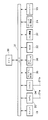
図1は代表的な文書の1ページを示している。図1において、文書ページ101は2欄形式に構成されている。ページには、タイトルに適切な大きいサイズのフォントのテキスト情報を含むタイトルブロック102と、テキストデータのラインを含むテキストブロック104と、非テキストのグラフィック画像を含むグラフィックブロック105と、表のテキストまたは数字情報を含む表ブロック106と、グラフィックまたは表情報のブロックの説明文(caption)である小サイズのテキストデータを含むキャプションブロック107とが含まれている。各情報のブロックはそこに含まれる情報のタイプに基づいて分類され、その分類に応じて分割される。
【0005】
【発明が解決しようとする課題】
予め、画像データのテキストタイプのブロックを検出するために、画像データにおける黒画素を水平及び垂直に展開して、水平及び垂直に隣接する単数または複数の白画素に展開することで画素画像データをにじませる(スミアー技術)ことが考えられた。こうしたスミアー技術は、スミアーパラメータを適切に選択することができる様に、テキストタイプ画像データの文字の予備知識(例えばフォントサイズ)に依存しているため、不十分である。さらに、スミアーパラメータの小さな変化で選択結果に大きな変化が生じる。スミアー技術はまた、必ず原稿文書の内部構造を保持できるわけではない。例えば、スミアーにより2欄形式の原稿が1欄に変わってしまうことがある。このような状況は、テキストデータが格納されている順序を狂わせ、原稿テキストの正確な再構成を不可能にしてしまうことから、不都合である。さらに、スミアー技術では、時折テキストタイプデータを非テキストタイプデータ中ににじませ、全体の領域がテキストタイプデータとして誤認識されることが知られている。
【0006】
同出願人による、1992年4月24日出願の米国特許出願第07/873、012号では、格納された文書内の文字ブロックを選択するための他の方法が提案されている。そこでは、格納された文書に対し、最初に所謂「結合成分(connected components)」のサーチが行なわれる。これは、各画素の周囲の8方向のいずれかに存在する、2つ以上の画素が結合されたものである。次に、テキスト結合成分は非テキスト結合成分から分離されて、非テキスト結合成分は、例えば、表、中間調画像、線画等として分類される。次に、文書の何らかの歪みの方向が検出され、もし歪みが垂直ならば画像は90度回転され、結合成分のサーチが再び行なわれる。歪みの補正の後、テキストの適切なブロック、例えば欄が識別される様に、非テキスト成分のエッジに添った目に見えない白ラインがサーチされる。その後、水平テキスト列とタイトル列が形成され、水平テキスト列はグループ化されて四角形に配置されたテキストブロックになる。そして、後処理が行なわれて、更なる文字認識処理のために、識別されたテキストブロックが準備される。07/873、012号は参照により本願に併合されている。
【0007】
上記のブロック選択技術は水平文書(例えば英語文書)に適切であるが、1ページが水平及び垂直テキストブロック(2方向)を含んでいる場合にも適用可能である。例えば、日本語の文書は垂直な漢字文字と表や数字記号などの水平な文字との組み合わせを含んでいる。また、ある種の英語文書は特定の情報を強調したり、所望の効果を提供するために、垂直に配置された文字を含んでいる。
【0008】
さらに、スキャンされたページ自体はしばしば歪んでおり、上記のブロック選択技術では、最初に歪みを識別して、テキストブロックを形成する前に画像を回転させることでこの問題に対処している。この技術を実用化する際には、処理速度と正確さにおいて2つの実質的な問題となる。さらに詳しくは、上記のブロック選択技術では、ブロック領域は四角形で表され、非テキストブロックの境界もまた記録される。しかし、歪んだ文書の場合、四角形はテキストブロック間の分離を不明瞭にして、実際重なることもある。これにより、ブロック内のデータの誤分類が起こり、文字認識のエラーとなることもある。
【0009】
従って、垂直及び水平テキストブロックが認識され、テキストブロック形成の前に歪んだ文書を回転させる必要の無い、格納文書におけるテキスト及び非テキストブロックを効果的に且つ効率的に選択するための方法及び装置が求められている。これにより、処理時間を節約し、認識精度を向上させる、より柔軟なブロック選択技術が提供される。
【0012】
【課題を解決するための手段】
上記の目的を達成する本発明の一つの態様によるブロック選択方法は、
画像データにおける黒画素の連続成分を検出する連続成分検出工程と、
前記検出された連続成分を、サイズ及び他の連続成分との相対的位置に基づいて、テキスト又は非テキストに分類する分類工程と、
少なくとも一部が前記分類工程で分類された非テキストの連続成分のエッジに沿っており且つ当該非テキストの連続成分に隣接する領域へ延びる不可視の直線をサーチするサーチ工程と、
前記分類工程で分類されたテキストの連続成分の相対的位置に基づいて、テキストブロックを形成するテキストブロック形成工程と、
前記テキストブロック形成工程で形成されたテキストブロックを、前記非テキストの連続成分の可視線または前記サーチ工程でサーチされた不可視の直線が横切っている場合、当該テキストブロックを当該可視線または不可視の直線で分割する分割工程と、
前記分割工程で分割されたテキストブロックに対して、所定の後処理を実行する後処理工程とを備える。
【0013】
また、上記の目的を達成するための本発明の他の態様によるブロック選択装置は以下の構成を備える。即ち、
画像データにおける黒画素の連続成分を検出する連続成分検出手段と、
前記検出された連続成分を、サイズ及び他の連続成分との相対的位置に基づいて、テキスト又は非テキストに分類する分類手段と、
少なくとも一部が前記分類手段で分類された非テキストの連続成分のエッジに沿っており且つ当該非テキストの連続成分に隣接する領域へ延びる不可視の直線をサーチするサーチ手段と、
前記分類手段で分類されたテキストの連続成分の相対的位置に基づいて、テキストブロックを形成するテキストブロック形成手段と、
前記テキストブロック形成手段で形成されたテキストブロックを、前記非テキストの連続成分の可視線または前記サーチ手段でサーチされた不可視の直線が横切っている場合、当該テキストブロックを当該可視線または不可視の直線で分割する分割手段と、
前記分割手段で分割されたテキストブロックに対して、所定の後処理を実行する後処理手段とを備える。
【0017】
なお、これらの及び他の本発明の特徴及び有利な点は、以下の添付の図面に従う好適な実施例の詳細な説明を参照することにより、さらに容易に理解されるであろう。
【0018】
【実施例】
以下に添付の図面を参照して本発明の好適な実施例を説明する。
【0019】
本発明は、複写機、ファクシミリ装置、ビデオまたはスチルビデオカメラ、レーザビームプリンタ等の、文字認識処理が望まれる画像処理または画像再生装置などの様々な装置において実現される。そうした装置では、文字画像を含む画像は、文字画像が文字認識処理される様に処理または再生される。必要であれば、認識された文字画像を標準化された文字セットまたはフォントに換えて、原稿の文字画像ではなく標準化された文字を再送信したり再生したりすることもできる。本発明はまた、汎用コンピュータや、パーソナルコンピュータ、ワードプロセッシングまたはデータ処理機器等のオフィス機器、複数のビジネス機器ツールを1つの統合パッケージにおいて結合した統合オフィスオートメーション機器等においても実現され得るものである。
【0020】
図2は本発明の代表的な実施例の外観を示す図である。図2において、IBM−PC(商標)またはPC互換性を持つコンピュータ等のコンピュータ10が示されており、コンピュータ10は、マイクロソフトウインドウズ・オペレーティングシステム(商標)等のグラフィカル・ユーザインタフェース・オペレーティングシステムを備えている。コンピュータ10にはカラーモニタ等の表示画面11が設けられている。コンピュータ10は、さらに、白黒、中間調、カラービットマップ画像等のデータファイルを格納したり、コンピュータ10がデータファイルを操作したり、表示画面11を通じてデータをオペレータにファイルの形で提示するためのプログラム・インストラクション・シーケンスを含むアプリケーションプログラムファイルを格納するための、コンピュータディスクドライブ14等のマスク格納装置を備えている。例えば、ディスクドライブ14上のアプリケーションプログラムは、光ディスク上のデータにアクセスするアプリケーションプログラムや、他の情報処理プログラムを含むものである。
【0021】
テキストデータ入力や、オペレータが表示画面11に表示されたデータの選択や操作を行なうためのキーボード15がコンピュータ10に接続されている。さらに、表示画面11上で処理対象物の選択や操作を行なうための、マウス等のポインティングデバイス16が設けられている。スキャナ18は文書または他の画像を走査して、例えば、それらの文書のビットマップ画像をコンピュータ10に提供する。それらの画像はコンピュータ10により直ちに使用されるか、あるいはコンピュータ10はこれらの画像をディスクドライブ14へ格納したり、または光ディスクドライブ20を介してディスク19等の光ディスクに格納する。引き続くコンピュータ10による処理のために、ビットマップ画像データはディスク19またはコンピュータディスクドライブ14から検索される。電話リンク21またはネットワーク22を介して、コンピュータ10内の不図示のモデムを通じて、ビットマップ画像データ及び他のデータを供給するための他の手段も設けることができる。さらに、取り外し可能なフロッピーディスクドライブを設けることも可能であり、または、不図示のビデオインタフェースを介して、デジタルまたはアナログのビデオ情報をコンピュータ10に入力してもよい。
【0022】
コンピュータ10により処理された情報を出力するために、プリンタ24が設けられている。
【0023】
コンピュータオペレータ命令に従って、そしてオペレーティングシステムの制御下で、格納されたアプリケーションプログラムが選択的に作動され、入力されたデータの処理や操作を行なう。例えば、以下に詳細に説明する様に、文字認識プログラムは、オペレータがスキャナ18を介して文書画像をスキャン入力し、スキャンされた画像を光ディスク19へ格納するために動作する。オペレータはオペレーティングシステム及びアプリケーションプログラムに従って、スキャン入力した文書を光ディスク19から検索することができる。
【0024】
図3は本発明の1実施例の詳細なブロック図であり、スキャニング、ファクシミリ、情報送信及び受信、そして情報処理能力を有し、情報処理能力としては選択的にワードプロセッシング及びデータ処理能力を有する統合オフィスオートメーション機器に関するものである。
【0025】
図3の装置において、画像はファクシミリ送信や、原稿のスキャン入力や、モデムを介した遠隔受信等によって入力される。本実施例によれば、画像中の文字を認識して、認識された文字のコンピュータテキストファイルを作成し、装置のワードプロセッシング、スプレッドシートプロセッシングまたは他の情報処理能力を使用してテキストファイルを修正することができる。修正されたテキストファイル(または修正を行なっていないテキストファイル)は再送信されたり、あるいは、例えばテキストファイルをスピーカまたは通常の音声電話機により音声再生するスピーチ合成技術を用いて出力することができる。
【0026】
図3では、プログラム可能なマイクロプロセッサ等の中央処理装置(CPU)30がバス31と接続されている。さらにバスには、画像を画素単位で画像メモリ(例えば下記のRAM32)へスキャン入力するスキャナ18、デジタルデータをアナログ形式で電話線21aを介して送受信するモデム33、及び画像を電話線21bを介して送受信するファクシミリ装置34(所望により不図示の電話を含む)が接続されている。電話線21a、21bは同じ線でもよいし、不図示のネットワーク制御部を通じて統合されていてもよい。バス31には、さらに、CPU30に実行される単数または複数のコンピュータプログラムを格納する読み取り専用メモリ(ROM)35、認識処理の間に入力された文字が参照される文字の辞書を格納する文字ディクショナリ36、入力された画像データ、処理された画像データ、画像構造に関する情報等を格納するランダムアクセスメモリ(RAM)32、文字認識処理の間に認識された文字の識別が出力される出力装置37(ディスクメモリまたはスピーカ/音声電話線インタフェースを有するスピーチ合成装置)、本装置によって処理された画像を表示するプリンタ/表示装置24、及びオペレータが装置を制御するためのキーボード15が接続されている。
【0027】
バス31に接続された装置は1つの統合オフィスオートメーションツールに収納されているが、これらの装置の幾つかあるいは全てが選択的にスタンドアロン形式で提供され得ることも明らかである。
【0028】
スキャナ18、モデム33、ファクシミリ34は、画像データを装置へ入力する選択的な形の入力手段を構成している。スキャナ18を使用した場合、原稿はライン単位、画素単位でスキャンされて、そしてCPU30の制御下で、画像データの画素がRAM32の画像メモリにビットマップメモリ形式で格納される。モデム33を使用した場合、画像データは電話線21aよりアナログ形式で受信され、モデム33によりデジタル画素形式に変換され、RAM32の画像メモリに格納される。ファクシミリ34を使用した場合、画像データは修正ハフマンランレングス符号化方式等で圧縮または符号化された形で、電話線21bより受信される。圧縮画像データは、ファクシミリ34によって公知の技術によりデジタル画像画素データに伸張(uncompressed)され、CPU30は画像データの画素をビットマップ形式でRAM32の画像メモリに格納する。他の入力手段も勿論使用可能である。例えば、画像データは、ディスクメモリ等の大型記憶装置から簡単に検索して獲得することができ、また、ビデオまたはスチルビデオカメラから得ることもできる。
【0029】
ファクシミリ34と出力装置37は、文字認識された画像データを装置から出力するための選択的な出力手段を構成している。ファクシミリ34を使用した場合、本実施例に従って認識処理された文字画像は標準文字セットまたはフォントに変換され、装置から送信することができる。これにより、例えば、文字画像を含む画像の受信、文字画像の文字認識、再送信前に行なう認識された文字の標準文字フォントへの変換が可能となり、劣化した画像品質を向上させる。
【0030】
モデム33及び出力装置37は、画像データの認識された文字の識別を、例えばASCIIコードで出力したり格納するための選択的な手段である。文字の識別は装置内に(ディスクメモリ内等に)格納され、または送信のためにモデム33を介して遠隔ロケーションへ出力される。ASCIIコード等の文字の識別をファクシミリ互換性のある形式へと形式再変換するための手段を設けることも可能で、ファクシミリ34を起動することなく、モデム33を通じて離れて位置するファクシミリ装置へ送信することができる。
【0031】
プリンタ/表示装置24は、文字認識のいずれかのステップのための恒久的な記録を出力及び形成するだけではなく、文字認識処理の過程を監視するための手段である。キーボード15は、オペレータが図3の装置の操作を制御するためのものである。
【0032】
図4は本実施例によるブロック選択技術が有益に使用される1方法を理解するのに役立つ、全体的な文字認識処理を示すフローチャートである。図4の処理ステップは、プログラムROM35に格納されたコンピュータプログラムに従ってCPU30により実行される。
【0033】
ステップS401では、画素画像データが装置へ入力されRAM32へ格納される。画像データは画像を画素単位で表現している。好ましくは、画素データは2値画素データ、つまり白黒画像データである。しかし、画像データは、各画素が複数のグレイスケールレベルの内の1つで表現される中間調画像データであってもよいし、各画素が、その色を符号化するマルチビットワードで表現されるカラー画像データであってもよい。それらの場合または画素データが2値画素データではない他のいずれの場合でも、RAM32へ格納する前に、非2値画素データを2値画素データへ変換するための閾値処理が行なわれる。
【0034】
好ましくは、ステップS401で入力された画素画像データはポートレートタイプの画像、つまり左上隅から右下隅まで読んだ画像である。もし画像がその様に構成されてない場合、例えば、ランドスケープタイプの画像である場合、画素画像データは、ポートレートタイプの画像を表現する様に翻訳される。翻訳は、画像データを翻訳することを命じる、キーボード15を介したオペレータ入力の命令に従って行なわれる。
【0035】
ステップS402では、画像データが前処理される。通常、劣化した文字や画像を向上させること等により画像データを補強する様に前処理フィルタが使用される。適切な画像補強技術は、同出願人による、1991年10月4日出願の審査中の米国特許出願第07/771、220号で説明されている。
【0036】
ステップS402で、必要であれば、認識処理の速度を上げるために、可能な程度に精度とコストを落として、画素画像データの画素数を減らすか、圧縮を行なってもよい。例えば、m×nブロックの画素(mとnは異なる)の画素値を平均して、そのm×nブロックの平均値の単一の画素に変換することを行ってもよい。
【0037】
ステップS403では、画像の各セグメントにおける画像データのタイプを特徴付け、テキスト情報、グラフィックス情報、ライン画像情報、写真情報等の情報のブロックを指定して識別するために、ブロック選択が行なわれる。さらに、ステップS403のブロック選択では、画像の各部分が、後述のステップS412で説明される様な適切な順序に再構成される様に、階層的ツリー構造への画像の配置も行なわれる。例えば、階層的ツリー構造には、2つの欄の画像データが、欄1よりのテキストが欄2よりのテキストへ読み込まれるのを防止する様に、欄1のテキストを欄2のテキストに先行して再構成する情報が含まれている。ステップS403によるブロック選択を以下に詳細に説明する。
【0038】
最初の情報のブロックがRAM32に格納された画像から選択され、ステップS404では、それがステップS403で決定されたブロック識別に基づいてテキストブロックか否かが決定される。その最初のブロックがテキストブロックではない場合、ステップS405へ進み、次のブロックが選択されて、ステップS404へ戻る。
【0039】
ステップS404で、ブロックがテキストブロックである場合はステップS406へ進み、テキストブロックに対しライン分割が行なわれる。ライン分割では、テキストブロックにおけるテキストの個々のラインがテキストブロックのテキストの他のラインから分割されて、分割されたラインは、次に詳細に説明される様に順次処理される。
【0040】
ステップS407では、あるラインの各文字が、そのラインの他の文字から切り離しあるいは分割され、個々の文字が次に詳細に説明される認識処理ルーティンに提供される。
【0041】
ステップS408において、各文字に対して認識処理が文字単位で行なわれ、各文字は、文字ディクショナリ36に格納された標準文字と公知の技術で比較される。文字ディクショナリ36のエントリは、通常単一の文字に対するものであるが、ある文字の連続は切り分けるのが困難であり(例えば「fi」)、また単一の文字も時折不用意に切れるので(例えば「j」)、文字ディクショナリは一文字以外の他のエントリも有している。得に、ディクショナリは切り離しが困難な接触文字の組のためのエントリを有している。さらに、ティクショナリはしばしば不用意に切れる文字の部分のためのエントリも有している。
【0042】
比較に基づいて、文字画像に対してある識別が選択されて、RAM32へ格納されるか、または出力装置37へ出力される。また、所望により、識別された文字をプリンタ/表示装置24上で表示してもよい。
【0043】
ステップS409では、テキストブロックに対する処理が完了したかどうかを判定する。処理が完了していない場合は、ステップS406(または、ステップS407が適切ならばステップS407)へ戻り、更なるライン分割または文字分割処理を行なう。ブロック処理が完了すると、ステップS410へ進んで、ページに対する処理が完了したかどうかを判定する。ページの処理が完了していない場合は、ステップS405へ戻り、そこで同じページの次のブロックが処理のために選択される。
【0044】
ページの処理が完了すると、ステップS410からS411へ進み、後処理が行なわれる。後処理にはコンテクストチェッキングやスペルチェッキング等の技術が含まれ、ステップS408において実行された処理の様に個々の文字に基づくよりはむしろ、それらの文字の識別が生じるコンテクスト(全体的観点)に基づいて、ステップS408の認識処理で認識された文字の識別結果が修正される。
【0045】
ステップS412では、画像データはブロック選択ステップS403で規定されたツリー構造に基づいて再構成される。ページ再構成により、画像データは、適切な順序に変換される。例えば、脚注は本文テキストから切り離され、欄は他の欄と混合されるというよりは、むしろその欄の後へと続き、グラフィックまたは線画データはページの認識された文字テキストにおける適切な位置へ挿入される。
【0046】
上述のグラフィック画像または線画像に関連する説明文(caption)はそれらの画像に隣接して挿入される。他のルールも適用可能である。例えば、ページの物理的再構成は必要ではない場合に、ページからテキストを抽出するために再構成を行なう、ということも可能である。
【0047】
ステップS413では、再構成されたページは例えば出力装置37に格納される。そして、ROM35に格納された他のアプリケーションプログラムに従い、CPU30により実行される形で、スプレッドシートやワードプロセッシング等の情報処理が行なわれる。続いて、処理された情報(または必要であれば処理を行なっていない情報)は、様々な手段により、例えばファクシミリ34、モデム35、またはコンピュータテキストファイルを音声再生するスピーチ合成装置による通常の音声電話機により、再送信される。
【0048】
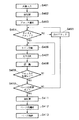
図5は図4のステップS403におけるブロック選択処理を説明するための全体的なフローチャートである。ただし、ブロック選択処理は文字認識システムとは別に使用される。例えば、画像再生機器において、あるタイプのブロックに用いられる第1の画像再生方法を生じ、次のタイプのブロックに用いられる第2の画像再生方法を生じるため、またはデータ圧縮方式におけるブロック選択を使用するために、ブロック選択処理を用いることが可能である。
【0049】
ステップS50では、ブロック選択処理速度を上げることが必要であれば、画像補強及び/またはデータ縮小を行なうことができる。データ縮小が行なわれると、ブロック選択は縮小された画像に対して行なわれる。しかし、図4の文字認識処理(つまりステップS404〜S413)に影響を与えない様に、ブロック選択処理の終了時点で、選択されたブロックは縮小されていない画素画像データに対して適用される。
【0050】
画像データ縮小はm×m画素ブロック毎に黒画素の連続性を評価することにより進められる。例えば、3×3画素のブロックにおいて2つの連続する黒画素が存在すれば、その3×3画素ブロックは単一の黒画素に縮小される。逆に、3×3画素ブロックに2つの連続する黒画素が存在しなければ、その3×3画素ブロックは単一の白画素に縮小される。好ましくは、4×4画素ブロックの黒画素の評価が行なわれる。この原理は原画像の連続性を保持するためのものである。
【0051】
ステップS51では、画素画像が分析された、連続成分が検出され、その大きさ及び他の連続成分との相対的位置に基づいて、検出された連続成分が分類される。連続成分は白画素によって完全に囲まれた黒画素のグループである。従って、連続成分は、少なくとも1つの白画素によって他の黒画素のグループから分離された黒画素のグループである。図6を参照して詳細に後述するが、ステップS51では連続成分(各画素を囲む8方向の内いずれかで連続した成分)の検出が行なわれる。ステップS52では、連続成分から得られたサイズ情報及びある統計上の値(下記に詳説する)に基づいて、各連続成分に分類が割り当てられる。詳細は後述するが、各連続成分はテキストユニットまたは非テキストユニットとして分類される。ステップS53において、非テキストユニットは更なる分類に掛けられ、フレームデータか、中間調画像か、線画か、表かまたは他のテーブル状の構造のテキストデータか、垂直線か、水平線か、垂直または水平な斜線であるか、または未知の分類に相当するかどうかが、その厚さや黒画素の割合に基づいて判定される。連続成分の組織的データを提供し、ステップS412で前述した様にデジタルデータの再構成を助成するために、各連続成分に対して階層ツリー構造が展開される。
【0052】
ステップS54では、非テキスト連続成分のエッジに沿って不可視線(白線)がサーチされる。このような不可視線を使用する理由は、テキスト欄の間の距離が、同じページの大抵の欄の隙間よりも例外的に狭いものがあるためである。こうした不可視線の検出は、後で隣接するテキスト連続成分が実際は同じブロック内にグループ分けされるべきかどうかを判定するのに役立つ。
【0053】
ステップS55では、ステップS51で分類することができなかった非テキストユニットが分析されて、大きいフォントサイズのタイトルであるかどうかが判定される。タイトルである場合は、ユニットは適切に再指定されて、ツリー構造が更新される。タイトルはステップS412におけるページ再構成に役立つものである。未知の非テキスト及びステップS52、S53で識別されたテキスト成分をグループ化することにより、水平または垂直方向にタイトルラインが形成される。このグループ化の前に、グループ化されると想定される成分の間の距離と、タイトルが水平または垂直である場合に可能なタイトルの長さとに基づいて、グループ化の方向が決定される。
【0054】
ステップS56では、後述するが、テキストブロックがテキスト連続成分から形成される。ステップS57では、形成されたテキストブロックを可視線または不可視線が横切っていた場合、テキストブロックは分割される。これらの線を使用する理由は、極端に狭い欄間の隙間のためだけではなく、異なるブロックのテキスト連続成分の間の距離が、斜めの場合に、特に不可視または可視線がそれらを分けている場合に、それらの成分が1グループにするのに十分に短くできるためである。
【0055】
ステップS58では、各テキストブロックの方向が検出される。この様に、本実施例によれば、テキストブロックが形成される前には歪み検出も画像回転も行なわれることはない。こうして、一般のブロック選択アルゴリズムとは異なり、本実施例は予め歪み検出や画像回転を行なうことなく、ページ画像に直接テキストブロックを形成する。これにより、画像回転に費やされる時間が節約され、歪み検出による不正確さを避けることができる。さらに、ある特殊な視覚効果を達成するために、同じページのテキスト領域の幾つかを、特別に斜めに編集することも可能である。こうした場合、歪み検出及び画像回転は、ページ画像を直立スタイルに修正するのに役立つことになる。こうして、本実施例によれば、テキスト及び非テキストブロックは、スキャンされたページの歪みに係わり無くサーチされる。テキストブロックが形成された後、各テキストブロックの歪み方向が個別に識別される。
【0056】
ステップS59では、テキストブロックの方向に基づいて、各テキストブロックのテキストラインが形成される。ステップS60では、テキスト及び非テキストブロック表現をより簡潔で明瞭にするために後処理が行なわれる。例えば、以前のブロック選択アルゴリズムは四角形で表現されたテキストブロックを形成するものであった。しかし、歪んだ文書の場合、そうした四角形ではテキストブロックの分離が不明瞭になる。テキストブロックの四角形領域が重なる場合にテキストブロック間の分離を明白にするために、本実施例では各テキストブロックをより簡潔に囲む不規則な形状の曲線を提供するものである。この曲線による囲みは表示効果を補強するだけではなく、ブロック画像の抽出にも有効である。テキストブロックを囲む不規則形状の曲線は、テキストブロック形成ステップS56でテキストブロックが新たに形成または更新される度に形成することができる。
【0057】
図6A、図6B、図6C、図6Dは、上述のステップS51〜S53の処理を詳細に示すフローチャートである。このフローチャートには、画素画像データの連続成分がどの様にして検出されるか、またそれらの連続成分がどの様にして分類されるかが示されている。図6A〜図6Dの各処理ステップは、プログラムROM35に格納されたプログラムステップに従ってCPU30により実行されるものである。
【0058】
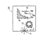
ステップS601では、輪郭トレーシングにより画素画像データの連続成分が検出される。輪郭トレーシングは図7Aに示す様な画像データをスキャンすることにより行なわれる。スキャニングは矢印Aで示される様に画像の右下部から左へと進み、画像の右の境界に到達するまで続く。スキャニングは、例えば左上から右下へ向けたり、他の方向へも行なうことができる。黒画素があると、隣接する画素が符号71で示される様な放射状のパターンになった順序で調べられ、黒画素の隣接画素も黒画素であるかどうかが判定される。放射状パターン71は共通の中心から延びる8つの番号の付いたベクトルを持つので、以下この輪郭トレーシングは「8方向」トレーシングと称される。隣接する黒画素が見つかると、処理は上述の様に画像の外郭のトレースが終わるまで進められる。こうして、図7Bに示す様に、矢印Aの方向のスキャニングは文字「Q」の尾の部分に対応する点72を突き止める。隣接画素の捜査は、文字「Q」の外郭がトレースされてしまう様に、放射状パターン71に従って進められる。閉じた輪郭の内側の部分はトレースが行なわれない。
【0059】
1つの連続成分が検出され、その輪郭が8方向トレーシングによりトレースされた後、スキャニングは次の黒画素が見つかるまで進められる。こうして、例えば、完全に黒く塗りつぶされた領域を表すオブジェクト74が8方向トレースされる。同様に、単語「non-text」を示す手書き文字の非テキストオブジェクト75が、単語「text」を形成する個々の文字からなるテキストオブジェクト76における個々の単語と同様にトレースされる。図7Aに示すスキャニングは画素データの全ての連続成分が検出されてその輪郭が8方向トレースされるまで続けられる。
【0060】
そして、ステップS602に進み、各連続成分が四角形化される。詳しくは、各連続成分の周りに最小の可能な四角形が描かれる。こうして、図7Bに示す様に、四角形77がオブジェクト72の周りに、四角形79がオブジェクト74の周りに、四角形80がオブジェクト75の周りに、そして四角形81a、81b、81c、81dがテキストオブジェクト76a、76b、76c、76dの周りに夫々描かれる。
【0061】
ステップS603では、ツリーの位置が各四角形に割り当てられる。殆どの部分について、ステップS603で得られたツリー構造は画素画像における各オブジェクトに対し直接ツリーの根から進んでいる。これは、連続成分の外郭のみがトレースされ、閉じた輪郭の内側の部分はトレースされないためである。この様に、図7Cに示す様に、連続成分72に相当する四角形77はページの根から直接進んでいる。しかし、非テキストオブジェクト75に相当する四角形80や、テキストオブジェクト76a、76bに相当する四角形81a、81bの様な、その四角形が他の連続成分の四角形の中にすっかり収まっている連続成分については、そうした連続成分を囲んでいる成分(この場合成分74)からの末裔として指定されている。さらに、少なくとも1つの枝分れ成分を持つ各連続成分については、その成分自身からの「主末裔成分」として指定されている。この様に、成分79は他の末裔成分80、81a、81bの中に自身79からの主末裔成分として指定されている。
【0062】
ステップS604では、ツリーの最初のレベルにある連続成分が、テキストユニットまたは非テキストユニットに分類される。分類は2つのステップで進む。最初のステップでは、連続成分の四角形が所定の大きさの閾値と比較される。連続成分を囲む四角形の高さ及び幅が最大フォントサイズに相当する第1の所定閾値より大きい場合、連続成分は非テキストユニットと分類されて「非テキスト」属性がユニットに与えられる。
【0063】
第2のステップでは、全てのユニット、つまりまだ非テキストとして分類されていないユニットが、残りの全ての連続成分の集合的なサイズに基づいて適応的に決定された閾値と比較される。詳しくは、非テキストの指定がされていない全ての四角形のうちで通常のテキストサイズの大きい方(12pt)及び中間のサイズ(中間の高さと中間の幅のうち小さい方の四角形が選択される。選択された値はスカラーで乗算され(説明の都合で、1.5として選択されている)、高さ及び幅について適応的に決定された閾値とされる。決定された閾値より大きい全てのユニットは非テキストであると推定され、その様に分類される。一方、適応的に決定された閾値のいずれかより小さく所定のテキスト特性に合うユニットはテキストと推定される。ユニットはこの様に分類され適切な属性が与えられる。これらの分類は図6A〜図6Dの残りで述べられる様な精密な分類であり、下記により詳細に説明する。
【0064】
ツリーの第1のレベルの各ユニットがテキストまたは非テキストとして分類された後、テキストユニットの主末裔成分を含む全ての末裔成分がテキストユニットとして分類される。非テキストユニットの主末裔成分は非テキストとして分類されるが、非テキストユニットの他の末裔成分はテキストユニットとして分類される。
【0065】
ステップS606では、最初のユニットが選択される。ステップS606で、そのユニットがテキストユニットである場合は、ステップS607へ進んで次のユニットが選択される。非テキストユニットが選択されるまでステップS606〜S607が繰り返され、非テキストユニットが選択された時点でステップS608へ進む。
【0066】
ステップS608では、非テキストユニットが調べられ、そこからの末裔が存在するかどうかが判定される。例えば、図7Cに示す様に、非テキストユニット79は非テキスト主末裔79とテキスト末裔80、81a、81bを含んでいる。
【0067】
ステップS608において何らかの末裔が存在する場合、ステップS609へ進み、そのユニットがフィルタ処理され、そのユニットが中間調(またはグレイスケール)ユニットであるかどうか決定する。中間調フィルタリングでは、ユニットの末裔が調べられ、「ノイズサイズ」ユニットより小さいサイズの末裔の数が決定される。「ノイズサイズ」ユニットは、画像データについて予測された最小フォントサイズよりも小さい高さ及び幅を持つユニットである。ノイズサイズより小さいサイズの末裔の数が末裔の総数の過半数である時、ユニットは中間調画像であると判定される。従って、ステップS610よりS611へ進んで、「中間調」の属性が当該ユニットに与えられる。そしてステップS607へ戻り、処理のために次のユニットが選択される。
【0068】
ステップS609の中間調フィルタリングでユニットが中間調画像ではないと判定されると、ステップS610からS613へ進んで、ユニットからの主末裔が更なる処理のために選択される。そしてステップS614へ戻る。
【0069】
ステップS608で非テキストユニットに末裔が存在しないと判定されると、あるいはステップS613で主末裔が更なる処理のために選択されると、ステップS614でその主末裔にフレームフィルタリングが行なわれる。フレームフィルタリングは、問題のユニットがフレームであって、ユニットを囲む四角形の幅及び/または高さと夫々ほぼ等しい平行な水平線及び平行な垂直線を含んでいるかどうかを判定する様に設計される。特に、連続成分が調べられて、画素の各列について、ユニット内の連続成分の内側の部分をつなぐ最長の距離が決定される。こうして、図8Aに示す様に、非テキストユニット82は連続成分83を含み、その輪郭は84で示される様に8方向トレースされている。列「i」については、連続成分の内部をつなぐ最長距離は輪郭の左の境界85aから右の境界85bまでの距離Xiである。一方、列「j」については、連続成分の内部をつなぐ2つの距離が存在する。つまり連続成分の境界上の点86a、86b間の距離と、点87a、87b間の距離である。点86a、86b間の距離の方が点87a、87b間の距離よりも長いため、距離Xiは列jに関する連続成分の内部をつなぐ最長距離である。
【0070】
非テキストユニット82におけるn個の列の各々について、「x」距離が求められ、非テキストユニットがフレームであるかどうかを判定するために次の不等式がテストされる。
【0071】
【数1】

ここでXkはk番目の列に関し連続成分の内部をつなぐ最長の距離であり(上記の通りである)、Wは四角形ユニット82の幅であり、Nは列数であり、そしてたとえ画像においてフレームが歪んでいたり斜になっていてもフレームの検出ができる様に、閾値が予め算出されている。1°の歪みまたは傾斜角度を許容するためには、「sin(1°)×L+ステップS604で計算された平均テキスト高さに等しいオフセット」で満足な結果が得られることがわかる。
【0073】
上記の不等式が満足された場合、ユニットはフレームデータと判定され、ステップS615からS616へと進み、「フレーム」属性が当該ユニットに与えられる。
【0074】
ステップS616の後、フレームデータが表またはテーブル状に組織されたデータを含んでいる可能性を検討する。こうして、ステップS617(図6B)で、連続成分の内部が調べられて白輪郭が得られる。
【0075】
白輪郭はステップS601で検出された輪郭と同様であるが、黒画素よりも白画素が調べられる。こうして、図9Aに示す様に、非テキストユニットの内部が、矢印Bの方向に右下部から左上に向けてスキャンされる。最初の白画素が見つかると、その隣接画素が放射状パターン91に示される順序で調べられる。ただし、放射状パターン91は1から4まで番号が付けられたベクトルを有している。従って、このステップに従った白輪郭トレーシングは以下「4方向」白輪郭トレーシングと称される。白輪郭トレーシングは、黒画素に囲まれた全ての白輪郭がトレースされるまで4方向に行なわれる。例えば、白輪郭トレーシングは、96で示される、一般に指定された黒画素の様な、内部の他の黒画素に加えて黒画素セグメント92、93、94、95の内部輪郭を形成している画素に続くものである。白輪郭が見つかる度に、非テキストオブジェクトに囲まれた全ての白輪郭がトレースされるまで、スキャニングが上述の様に矢印Bの方向に進められる。
【0076】
ステップS618では、非テキストユニットの密度が計算される。密度は、連続成分の黒画素数を数えて、その黒画素数を四角形に囲まれた画素の総数で除算することにより求められる。
【0077】
ステップS619では、非テキストユニット内で見つかった白輪郭の数が調べられる。白輪郭数が4以上の場合は、非テキストユニットは実際は、表またはテーブル状に配置されたテキストブロックの連続である可能性がある。従って、ステップS620(図6D)で、白輪郭フィリング率が決定される。白輪郭フィリング率は、白輪郭が非テキスト画像で囲まれた領域を埋める度合いである。図9Aに示す様に、白輪郭フィリング率は、黒画素が見つかる白空間である100や101の様な領域に加えて、完全に空白の空間である97や99の様な斜線領域を含んでいる。フィリング率が高いと、非テキスト画像が表またはテーブル状に配されたテキストデータのシーケンスである可能性がある。従って、ステップS621でフィリング率が調べられる。フィリング率が高いと、非テキスト画像が表またはテーブル状に配されたテキストデータのシーケンスである可能性がある。この判定の信頼度を増すためには、白輪郭が調べられて、それらが水平及び垂直に拡がるグリッド状の構造を形成しているかどうかが判定される。詳しくは、ステップS622では、非グリッド配列の白輪郭は、その境界が少なくとも2つの輪郭を横切って水平及び垂直に延びていない場合は再結合される。例えば、図9Aに示す様に、白輪郭99の左の境界102と右の境界103は、白輪郭100の左の境界104と右の境界105に一致する様に垂直に拡がっている。従って、これらの白輪郭はグリッド構造に配置されているので、これらの白輪郭は再結合されない。同様に、白輪郭103の上部の境界106と下部の境界107は、白輪郭110の上部の境界108と下部の境界109に一致する様に水平に拡がっている。従って、これらの白輪郭はグリッド状構造に配置されているので、これらの白輪郭は再結合されない。
【0078】
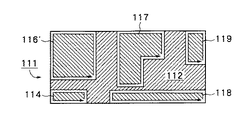
図9B〜図9Cは、白輪郭が結合される状態を説明するための図である。図9Bは、例えば、ステップS401において前述した様に中間調画像を2値画像に変換する閾値計算を通じて形成される、非テキストユニット111を示している。非テキスト画像111は、白領域114、115、116、117、118、119に加えて黒領域112を含んでいる。推定上、これらの白領域のフィリング率は、ステップS621から再結合ステップS622へ進める様に、十分に高くなっている。最初に、図9Bに示す様に、白輪郭115の上下境界が白輪郭117の上下境界と比較される。これらの上下境界は一致しないので、図9Cに示す様に白輪郭115は白輪郭116と再結合されて、結合された白輪郭116’を生成する。図9Cにおいて、白輪郭117の左右境界が白輪郭118の左右境界と比較される。これらの境界は同じではないため、図9Dに示す様に、白輪郭117と119は単一の白輪郭117’に再結合される。
【0079】
再結合が生じなくなるまで、この処理が水平及び垂直に反復される。
【0080】
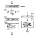
こうして、上述した様に、表に関する白輪郭は再結合される可能性が低く、非テーブルの白輪郭、例えば中間調画像または線画は再結合される可能性がより高い。従って、ステップS623で、再結合率が調べられる。再結合率が高い場合、またはステップS621でフィリング率が低い場合、非テキストフレームユニットは斜線、未知の画像(an unknown)、中間調画像または線画である可能性があり、ステップS628へ進んで非テキストユニットは表ではないとの指定がされて、後述のステップS642A(図6B)へ進む。
【0081】
ステップS623で再結合率が高くない場合は、ステップS624へ進み、非テキスト画像は「表類」として指定される。ステップS625では、8方向に連続成分を検出して分類する様に、新たに指定された表の内部が調べられる。ステップS626では、新しい内部の連続成分に基づいて、階層構造が更新される。ステップ627では、内部の連続成分はテキストまたは非テキストとして再分類され、ステップS602〜S604で前述した様に、適切な属性が与えられる。ステップS627の後、表内部のテキスト連続成分が線描画、中間調画、または未知の画であるかがサイズ、密度等に基づいて更に分類される。フレーム内部の非テキスト連続成分及び線描画内部の非テキスト連続成分も、ステップS608以降に説明した様に、更に分類される。
【0082】
ステップS621、S623において、ステップS621でフィリング率が高くない場合、またはステップS623で再結合率が高い場合は、非テキストフレームユニットは斜線、未知の画像、中間調画像または線画、つまり表ではない可能性がある。
【0083】
ステップS619において、白輪郭の数が4より少なければ、フレームユニットは表ではないと考えられる。従って、ステップS642Aへ進んで、フレーム及び密度が約0.5に等しい閾値より小さいかどうかが判定される。閾値は、フレーム内部のテキストユニットまたは線画が画素の半分より少ないとの推測に基づいて選択されたものである。フレーム及び密度が閾値より小さい場合、上述のステップS625〜S627へ戻り、その後、ステップS607へ進んで、次のユニットの選択が行なわれる。
【0084】
ステップS642Aにおいて、フレーム及び密度が所定の閾値より小さい場合、ステップS642へ進み、フレームユニットが線画または中間調画像に分類できるかどうか、あるいはフレームは分類できないか(つまり、フレームは「未知の画像」である)どうかが、より詳細に後述される様に決定される。
【0085】
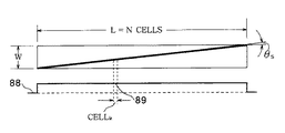
ステップS615(図6A)に戻って、ステップS614におけるフレームフィルタリングで非テキストユニット内のフレームが検出されなかった場合、ステップS635(図6B)へ進み、非テキストユニットがラインを含んでいるかどうかが判定される。ラインはテキスト境界を表す有用な非テキストユニットである。しかし、そうしたラインにより境界が引かれているテキストは、しばしばラインと近接しているため、そのテキストをラインに結びつけることが可能である。従って、テキストが近接した、またはテキストが近接していないラインを検出する様に、ライン検出が指定される。
【0086】
ラインを単独で検出するためには、ユニットの長さ方向で非テキストユニットのヒストグラムが計算される。図8Bに示す様に、あるラインのヒストグラム88は、ライン幅にほぼ等しい高さの、明らかに均一な分配を示している。ラインの幅は非テキストユニットの幅(W)にほぼ等しい。いずれの差異も、画素画像が形成される時に原稿文書が歪んでいた場合に結果として生じる傾斜角度θsによるものである。従って、非テキストユニットがラインを含んでいるかどうかを判定するためには、ヒストグラムにおける各cellkが、非テキストユニットの幅Wと比較される。次に示す様に、これらの値の二乗平均の平方根の差が、閾値と比較される。
【0087】
【数2】
閾値は、非テキストユニット内のラインの歪みまたは傾斜角度θsを許容するために算出されるものである。1°の歪みまたは傾斜角度に対しては、
【0089】
【数3】
の閾値で満足な結果が得られることがわかる。
【0091】
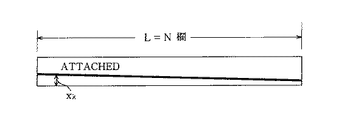
上記の式に従って近接物の無いラインが見つからない場合、そのユニットがテキスト近接ラインを含んでいるかどうかが判定される。テキスト近接ラインが非テキストユニットに含まれているかどうかを判定するにために、テキストユニットが調べられて、あるラインがユニット境界に沿って縦に延びているかどうかが判定される。詳しくは、もしあるラインがユニットの縦方向に延びていれば、図8Cに示す様に、ユニットを囲む四角形の境界がそのラインの非常に近くにあるということになる。従って、四角形の境界内にある最初の複数の黒画素における均一性が、境界からの距離の二乗の数の合計を計算することによって調べられる。このように、図8Cを参照すると、次の不等式がテストされる。
【0092】
【数4】
二乗の合計が所定の閾値より小さければ、テキストが接着したラインが見つかったことになる。接着物の無いラインに対して得られた閾値と同じ閾値で、満足する結果を得ることができる。
【0094】
ステップS635でラインが検出されると、ステップS636からS637Aへ進んで、「ライン」の属性が非テキストユニットに与えられる。そしてステップS607(図6A)へ戻り、次のユニットが選択される。
【0095】
一方、ステップS635でラインが検出されない場合、ステップS636からS637へ進んで、非テキストユニットの大きさが調べられる。サイズが所定の閾値より大きくなければ、非テキストユニットの分類は決定できない。閾値は最大フォントサイズ及び文書タイプ(水平、垂直、または両者混合)によって設定される。最大フォントサイズの半分だと満足な結果が得られる。従って、ステップS638へ進んで「未知」の属性が非テキストユニットに与えられ、ステップS607(図6A)へ戻って、次のユニットが選択される。
【0096】
ステップS637でサイズが所定閾値より大きければ、ステップS617、S618、S619へ進み、前述の様に、非テキストユニットの内部の白輪郭がトレースされ、非テキストユニットの密度が計算され、白輪郭数が調べられる。
【0097】
ステップS619で白輪郭数が4より大きくなければ、上述の様にステップS642A、S642へ進む。ステップS642ではユニットのサイズが計算されて、線画または中間調画像を構成できる程大きいかどうかが判定される。このサイズ判定は、黒画素の最大ランレングスに加えて、非テキストユニットの高さ及び幅と文書タイプ、に基づいて行なわれる。例えば、非テキストユニットの高さ及び幅が最大フォントサイズより大きくない場合は、その非テキストユニットは中間調画像または線画になる程大きくはないため、ステップS643へ進み、「未知」の属性が与えられる。さらに、非テキストユニットの幅は最大フォントサイズより大きいが黒画素の最大ランレングスは最大フォントサイズより大きくない場合も、ステップS643へ進み、「未知」の属性が与えられる。そしてステップS607(図6A)へ戻り、新たなユニットが選択される。
【0098】
ステップS642で、非テキストユニットが線画または中間調画像になる程大きい場合、ステップS643Aへ進み、非テキストユニットが水平または垂直の傾斜したラインであるかどうかが判定される。その後、ステップS644へ進み、非テキストユニットが線画か中間調画像であるかが判定される。ユニットが線画として、または中間調画像として分類されるかどうかは、ユニット内の黒画素の平均水平ランレングス、ユニット内の白画素の平均水平ランレングス、白画素対黒画素の比、及び密度に基づいて判定される。一般に、非常に暗い画像は中間調画像と考えられ、明るい画像は線画と考えられる。
【0099】
詳しくは、白画素の平均ランレングスがゼロにほぼ等しく(つまり、暗い部分が優勢または点描画の様な場合)、ステップS618で算出される様な密度が、ユニットが白より黒の方が強く(つまり、約1/2に等しい第1の閾値より密度が高い)、そして殆どの列が長い黒ランレングスを含んでいることを示す場合は、フレームユニットは中間調画像であると判定される。密度が第1の閾値よりも高くない場合は、ユニットは線画であると判定される。
【0100】
白画素の平均ランレングスがゼロにほぼ等しくはなく、白画素の平均ランレングスが黒画素の平均ランレングスより大きく、そして殆どの列に長い黒ランレングスが含まれていない場合は、フレームユニットは線画であると判定される。しかし、白画素の平均ランレングスが黒画素の平均ランレングスより大きくない(つまり、再び、暗い部分が優勢な画像である)場合、更なるテストが必要である。
【0101】
詳しくは、黒画素数が白画素数より大幅に少ない場合(つまり、白画素数で割った黒画素数が、2に等しい第2の閾値より大きい場合)、フレームユニットは中間調のユニットであると判定される。一方、白画素数で割った黒画素数は第2の閾値より大きくないが、ステップS618で求めた密度が第1の閾値より大きい場合は、ユニットは中間調画像であると判定される。そうでなければ、ユニットは線画であると判定される。
【0102】
従って、ステップS644でユニットが線画であると判定されると、ステップS645へ進み、「線画」の属性が与えられ、ステップS646で全ての末裔成分が現在の親成分から移動されて、2代前の親の直接の末裔とされる。詳しくは、一度ユニットが線画であると判定されると、文字認識のためにいずれのブロックも線画から選択されることはない。その後、ステップS625、S626、S627へ戻り、それからステップS607で次のユニットが選択される。
一方、ステップS644でユニットが線画ではないと判定されると、ステップS647へ進み、「中間調」の属性が与えられ、ステップS648で全ての末裔成分が現在の親成分から移動されて、2代前の親の直接の末裔とされる。そして、ステップS607へ戻り、次のユニットが選択される。
【0103】
本実施例は、上述のように判定された非テキストユニットに加えて、傾斜した垂直ライン及び水平ラインを、その厚さや完全性に基づいて識別する。
【0104】
ステップS53に2つの付加的機能を取り入れることも可能である。詳しくは、テキスト文字が下線より分離されるような、ライン近接物分離機能の実行が可能である。2番目の機能としては、点線、破線、または装飾された線(直線でも斜線でも)の検出が実行可能である。
【0105】
ライン近接物分離機能は、テキスト(あるいは他のテキストのサイズの近接物)が、何らかの非テキスト成分(直線、水平線、フレーム等)に付随しているように見える所に取り入れることができる。例えば、テキスト文字が下に引かれた水平線に近接しているように見える場所では、テキスト文字がテキスト連続成分として特徴付けられ、ライン画素が非テキスト連続成分として検出される様に、テキスト文字をラインから切り離す必要がある。
【0106】
テキストとラインの近接状態を分離する方法は、まずそうした近接物の存在を検出することで実行される。ラインの場合、ラインの片側のエッジはスムーズであると判定され、しかし反対側のエッジはスムーズではないと判定された場合、そのスムーズでない方のエッジに何らかの付着物が存在している。フレームの場合、外郭のエッジのいずれかがスムーズでない場合、そうしたフレームエッジに何らかの付着物が存在していることになる。
【0107】
次に、付着されたライン(またはフレームのエッジ)の2つの端点が算出されるが、これらの2つの端点の位置は非スムーズ側の画像アウトラインに基づいている。そして、「分離線」が算出された2つの端点の間を通って形成され、付着物は分離線に沿った線から切り離される。付着物はラインから「分離線」に沿って切り離され、付着物とラインはそれぞれ処理されて、付着物がテキスト連続成分か非テキスト連続成分かが判定されるが、好ましい形では、分離された付着物はテキスト連続成分として分類される。
【0108】
点線、破線、また装飾された線の存在を検出する方法は、垂直線、水平線、水平斜線、垂直斜線のいずれかの属性を各検出された線に与えることで実行される。そうした非連続線を検出するために、水平及び/または垂直な小さいサイズの(ピリオドの大きさと同様である)テキスト連続成分が収集される。次に、収集された成分は、それらの相対的な距離に基づいて異なるグループに分配される。各グループについては、そのサイズが水平、垂直、または斜線として十分かどうかが判定される。十分でなければ、そのグループが点線であり得るかどうかがチェックされる。対象のグループがラインとして可能であれば、グループはサイズとグループ間の間隙の明瞭度とに基づいて再編成される。その後、グループは再びチェックされて点線であるかどうか判定される。
【0109】
グループの幅が垂直線と同様であって、対象のラインの周辺に垂直なラインが存在し、グループとラインの間の間隙が明瞭であれば、グループは垂直線と考えられる。そうでない場合は、グループの長さが水平線と同じであるか、周辺に水平なラインが存在し、グループとこのラインの間の間隙が明瞭であるかどうかが判定される。そうである場合には、検出された非連続ラインは水平線であると決定される。
【0110】
画素画像における全ての連続成分が検出され、図6(図5のステップS53)で説明した様に分類されると、図10に示されるような修正されたツリーが得られる。図示の様に、ツリーの根は画素画像データのページに相当する。根から出ているのはテキストブロック、内容の不明な非テキストブロック、フレーム、写真、及び線の分類である。フレームから出ているのはテキストブロック、未知の非テキストデータ、写真や線のテキストブロックを含む表である。
【0111】
図5に戻り、ステップS53で全ての非テキスト連続成分が分類されると、ステップS54では非テキスト連続成分のエッジに沿った不可視線(白線)がサーチされる。そうした不可視線は(ステップS52で求められた不可視線も合わせて)、ステップS57で、可視または不可視線がテキストブロックを横切っている場合に、テキストブロックを分離するのに使用される。この手順は後で詳細に説明する。
【0112】
ステップS55で、ステップS53で分類された未知の非テキスト連続成分を用いて、水平及び垂直タイトルラインが形成される。これらの未知の非テキスト連続成分は、グループと想定される成分間の距離と、タイトルが水平または垂直である場合に可能なタイトルな長さとに基づいて、名目上垂直、水平、または傾斜のタイトルの方向を検出するのに使用される。この方法を用いて、各タイトル連続成分が水平及び垂直方向の非常に近接したブロックと比較され、より近いブロックに水平または垂直タイトルが添付される。
【0113】
ステップS56では、テキスト連続成分はテキストブロックを形成するのに用いられる。簡潔に述べると、各テキスト連続成分に対し、周辺にある近い水平及び垂直の成分がサーチされて、集成プロセスで、テキストブロックとしてグループ化される。プロセスを図11に従って詳細に説明する。
【0114】
図11において、ステップS52で識別されたテキスト連続成分を用いて、ステップS561でH−GAP及びV−GAPが計算される。これらはそれぞれ、隣接するテキスト連続成分間の水平及び垂直中央間隙部である。ステップS562では、全てのテキスト連続成分が、その垂直な位置によりソートされる。ステップS563では、現在のテキストブロックの形成が開始される。ステップS564では、ソート順に連続成分が抽出され、値V−DIST及びH−DISTとが計算される。これらの値はそれぞれ、抽出された連続成分と現在のテキストブロックの間の垂直及び水平距離である。利用可能な連続成分が存在しなければ、ステップS563へ戻り、次のテキストブロックが形成される。
【0115】
ステップS565では、抽出された連続成分について、V−DISTがV−GAPより大きいかどうか、またはH−DISTがH−GAPより大きいかどうかが判定される。ステップS565でいずれかに該当すれば、抽出された連続成分は現在のテキストブロック内には存在しないことになるので、ステップS564へ戻り、ソート順に次の連続成分が抽出される。一方、ステップS565でいずれにも該当しない場合は、抽出された連続成分は現在のテキストブロック内に存在することになるので、ステップS566へ進む。
【0116】
ステップS566では、抽出された連続成分と、現在のテキストブロックに既に含まれている連続成分とが、所定の条件を満たすかどうかが判定される。好適な実施例では、所定条件は図12に示される通りである。
【0117】
図12において、ステップS5661では、抽出された連続成分が現在のテキストブロックに既に含まれている連続成分と比較される。ステップS5662では、値h−dist及びv−distが計算される。これらの値はそれぞれ、抽出された連続成分とステップS5661で識別された1つの連続成分(テキストブロックに含まれている連続成分)との間の水平及び垂直距離を表している。
【0118】
ステップS5663では、v−distがV−GAPより小さいかどうか、そしてh−distがH−GAPより小さいかどうかが判定される。ステップS5663の条件に該当しない場合は、テキストブロックに含まれている連続成分は抽出された連続成分に十分に近似していないことになるため、ステップS5661へ戻って、現在のテキストブロック内の次のテキスト連続成分が抽出された連続成分と比較される。
【0119】
ステップS5663で条件に該当すれば、ステップS5664へ進み、抽出された連続成分がテキストブロックに含まれている連続成分とどのような垂直関係にあるのかが判定される。3つの関係が可能である。つまり、(1)抽出された連続成分が垂直にテキストブロックに含まれている連続成分の上にある、(2)抽出された連続成分は垂直にテキストブロックに既に含まれている連続成分の上ではなく、水平方向にある、(3)抽出された連続成分は垂直にテキストブロックに既に含まれている連続成分の上ではなく、斜め下方向にある、という関係である。条件(1)が満たされる場合、ステップS5665へ進むが、条件(2)または(3)が満たされる場合は、ステップS5667へ進む。
【0120】
ステップS5665では、現在のテキストブロック内に、抽出された連続成分に近い他の連続成分が存在するかどうかが判定される。これは、h−distがW−GAPより小さいかどうか(W−GAPはH−GAPより僅かに広い)を判定することにより確認される。該当しない場合は、ステップS5661へ戻って、現在のテキストブロック内の次の連続成分を用いて比較を行なう。しかし、ステップS5665において該当する場合は、ステップS5667へ進み、何らかの線描オブジェクト(例えば、ライン、線描画等)が抽出された連続成分とテキストブロックに含まれている連続成分の間に存在するかどうかが判定される。そのような線描オブジェクトが存在する場合は、ステップS564へ戻り、次の連続成分がパート順に抽出される。しかし、ステップS5667でそうしたオブジェクトが存在しないと判定された場合は、図11のステップS567へ戻る。
【0121】
図11に戻り、ステップS567では、ちょうど処理されたばかりの、抽出された連続成分が、ステップS52で識別された最後のテキスト連続成分であるかどうかが判定される。抽出された連続成分が最後の成分でない場合は、ステップS568で、その連続成分は現在のテキストブロックに挿入され、ステップS564へ戻って、ソート順に次の連続成分が抽出される。一方、ステップS567で最後の連続成分と判定された場合は、その成分は現在のテキストブロックに既に挿入されているので、図5のステップS57へ戻る。
【0122】
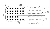
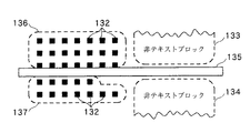
図5に戻って、ステップS57では、ステップS56で形成されたテキストブロックが単一のテキストブロックであるかどうか、または形成されたテキストブロックを横切る可視線または不可視線により、複数のテキストブロックに分割されるべきであるかどうかが判定される。例えば、図13Aはテキストブロック131を示し、テキストブロック131内には複数の連続成分132が配されている。テキストブロックに隣接するのは非テキストブロック133、134である。非テキストブロックの間にはステップS54で述べた不可視(白)線が存在している。例えば、非テキストブロック133、134が各々写真を含み、ブロックの間に不可視線が引かれている場合は、非テキストブロック133に隣接するテキスト連続成分は非テキストブロック133にのみ関係し、非テキストブロック134に隣接するテキスト連続成分は非テキストブロック134にのみ関係している。ステップS57で形成されたテキストブロック131が単一のテキストブロックである場合は、後に行なわれる文字認識処理で、非テキストブロック133、134を文字として誤認識する可能性がある。
【0123】
図13Bに示すように、不可視線135(または可視線)が先に形成されたテキストブロック131を横切っている場合において、テキストブロックは2つのテキストブロック136、137に分割される。そして、非テキストブロック133、134のそれぞれのテキスト連続成分が適切に処理される。ステップS57の後、ステップS58へ進み、各テキストブロックの方向が検出される。テキストブロックの方向の検出は、テキストブロック内のテキスト連続成分の長さ及び幅、連続成分間の水平及び垂直の間隙、及びそれらの位置に依存して行なわれる。図14A、及び、図14Bは、この処理を詳細に説明したフローチャートである。
【0124】
図14Aにおいて、まずステップS5801で、ステップS56で形成されたテキストブロック内の全てのテキスト成分について、様々な値が計算される。ただし、幅は水平寸法に相当し、長さは垂直寸法に相当するものである。値MAX−LEN及びMAX−WIDが計算されるが、これらはそれぞれ、テキストブロック内のテキスト連続成分間の最長の長さ及び最大の幅を表している。また値AVG−LEN及びAVG−WIDが計算されるが、これらはそれぞれ、テキストブロック内の全ての連続成分の平均の長さと幅を表している。最後に、値STD−LEN及びSTD−WIDが計算されるが、これらはそれぞれ、テキストブロック内の全ての連続成分の長さ及び幅の標準的な偏差を表している。
【0125】
その後、複数の処理ステップが実行されてテキストブロックが水平テキストブロックか垂直テキストブロックかが判定される。ステップS5802では、STD−LENがSTD−WID以下かどうか、MAX−WIDがMAX−LENより大きいかどうか、そしてMAX−WIDが12ptのプリントサイズ、もしくは1.5×MAX−LENよりも大きいかどうかが判定される(ここで、12pt値は通常のテキストサイズに基づいている。勿論、これより大きいまたは小さいテキストサイズの場合は、好ましくはダイナミックに調整できる異なる値が必要とされる)。これらの関係に該当すると、テキストブロックは水平テキストブロックであると決定される。これらの関係に該当しない場合は、ステップS5803へ進む。
【0126】
ステップS5803では、STD−WIDがSTD−LEN以下であるかどうか、MAX−LENがMAX−WIDより大きいかどうか、そしてMAX−LENが12pt、または1.5×MAX−WIDより大きいかどうかが判定される。これらの関係に該当すると、テキストブロックは垂直テキストブロックであると決定される。これらの関係に該当しない場合は、ステップS5804へ進む。
【0127】
ステップS5804では、各連続成分について、値H−SHORT及びV−SHORTが決定される。これらの値はそれぞれ、各連続成分及びその周辺の連続成分からの最短の水平及び垂直の間隙を表している。
【0128】
そしてステップS5805(図14B)へ進み、テキストブロック内の大抵の連続成分について、H−SHORTがV−SHORTより小さいかどうかが判定される。この関係に該当すると、テキストブロックは水平テキストブロックであると決定される。この関係に該当しない場合は、ステップS5806へ進んで、テキストブロック内の大抵の連続成分について、V−SHORTがH−SHORTより小さいかどうかが判定される。この関係に該当すると、テキストブロックは垂直テキストブロックであると決定され、該当しない場合は、ステップS5807へ進む。
【0129】
ステップS5807では、テキストブロック内の連続成分間の水平及び垂直の間隙の数が計算される。その後、ステップS5808では、水平間隙の数が垂直間隙の数より多いかどうか、またテキストブロックの幅が12pt×2より大きいかどうかが判定される。この関係に該当すると、テキストブロックは水平テキストブロックであると決定され、該当しない場合は、ステップS5809へ進む。ステップS5809では垂直間隙数が水平間隙数より多いかどうか、またテキストブロックの長さが12pt×2より大きいかどうかが判定される。この関係に該当すると、テキストブロックは垂直テキストブロックであると決定され、該当しない場合は、ステップS5810へ進む。
【0130】
ステップS5810では、テキストブロックの長さが12pt×2より小さく、全ての連続成分が同一の水平ライン上にあるかどうかが判定される。これに該当する判定であれば、テキストブロックは水平テキストブロックであり、該当しない判定の場合は、ステップS5811へ進む。ステップS5811では、テキストブロックの幅が12pt×2より小さく、全ての連続成分が同一の垂直線上にあるかどうかが判定される。この関係に該当すると、テキストブロックは垂直テキストブロックであると決定され、該当しない場合は、ステップS5812へ進む。
【0131】
ステップS5812では、テキストブロック内の全ての連続成分が垂直にソートされて、最初の連続成分と最後の連続成分が、重なる垂直領域を有しているかどうか検出される。それらが重なっていれば、テキストブロックは水平テキストブロックであると決定され、重なっていない場合は、ステップS5813へ進む。
ステップS5813では、テキストブロック内の全ての連続成分が水平にソートされて、最初の連続成分と最後の連続成分が、重なる水平領域を有しているかどうか検出される。それらが重なっていれば、テキストブロックは垂直テキストブロックであると決定され、重なっていない場合は、テキストブロックは未知のブロックである。
【0132】
識別された全てのテキストブロックの方向が一度決定されると、ステップS59へ進み、ステップS58で識別された方向に基づいて、各テキストブロックに関するテキストラインが形成される。図15はこの処理を詳細に示すフローチャートである。
【0133】
図15は水平テキストブロック内のテキスト連続成分の処理を示している。垂直テキストブロック内の連続成分の処理も同様であるので、詳細な説明は省略する。ステップS591では、水平テキストブロック内のテキスト成分が、その水平位置に従ってソートされる。その後、ステップS592では、ソーティングリストの次の連続成分が抽出され、その連続成分が既に存在しているいずれかのテキストラインに嵌入するかどうか検出される。この判定の詳細な処理は、図16A〜図16Eで示されるフローチャートを参照して説明する。
【0134】
図16Aでは、ステップS5921で、ステップS592で抽出した連続成分を用いて、値C−LINE1及びC−BLOCK1が計算される。C−LINE1は、抽出された連続成分と現在のテキストラインとの間のパーセントの垂直領域重畳部分を表し、C−BLOCK1は、抽出された連続成分と現在のテキストラインの末尾連続成分との間のパーセントの垂直領域重畳部分を表している。図16AのステップS5921は現在のテキストライン、その末尾の連続成分、抽出された連続成分、及びそれらの垂直領域重畳部分の関係を示している。
【0135】
ステップS5922では、C−LINE1がゼロより大きいかどうかが判定される。ゼロより大きくなければ、図16Eに従ってより詳細に説明されるステップS5936へ進む。一方、ステップS5922で、C−LINE1がゼロより大きいと判定されると、3つの値h−dist1、 v−dist1、NEXT−CLOSEST−LINEが決定される。h−dist1は、抽出された連続成分と現在のテキストラインの末尾連続成分との間の水平距離である。v−dist1は、抽出された連続成分と現在のテキストラインの末尾連続成分との間の垂直距離である。NEXT−CLOSEST−LINEは、(i)現在のラインの下にあり、(ii)その末尾連続成分が抽出された連続成分に最も近接しており、末尾連続成分と抽出された連続成分の間の距離は所定の距離内である、テキストラインである。そして、図16BのステップS5924へ進む。
【0136】
ステップS5924では、値C−LINE2、C−BLOCK2、h−dist2、及びv−dist2が決定される。C−LINE2は、抽出された連続成分とNEXT−CLOSEST−LINEとの間のパーセントの垂直領域重畳部分である。C−BLOCK2は、抽出された連続成分とNEXT−CLOSEST−LINEの末尾連続成分との間のパーセントの垂直領域重畳部分である。h−dist2は、抽出された連続成分とNEXT−CLOSEST−LINEの末尾連続成分との間の水平距離である。v−dist2は、抽出された連続成分とNEXT−CLOSEST−LINEの末尾連続成分との間の垂直距離である。
【0137】
その後、ステップS5925へ進み、C−LINE1が50%未満でC−LINE2が50%以上であり、そして現在のラインが上方向に傾き、NEXT−CLOSEST−LINEが上方向に傾いているかどうかが判定される。この関係に該当すると、ステップS5926へ進み、次の水平テキストラインが選択されて、図15のステップS592へ戻る。一方、この関係に該当しない場合は、図16CのステップS5927へ進む。
【0138】
図16Cにおいて、ステップS5927では、8つの関係が存在するかどうかが判定される。それらの関係は次の通りである。即ち、
(1) C-LINE2=0%
(2) C-LINE1≧50%、C-LINE2≦50%、
C-BLOCK1≧0%、C-BLOCK1>C-BLOCK2
(3) h-dist1>0、h-dist2>0、
(h-dist1<12pt、又はh-dist1<h-dist2)、
C-BLOCK1>0%、C-BLOCK1>C-BLOCK2
(4) h-dist1>0、h-dist2>0、
(h-dist1<12pt、又はh-dist1<h-dist2)、
C-BLOCK1>0%、現在のラインは下方向に傾き、
NEXT-CLOSEST-LINEも下方向に傾いている
(5) h-dist1>0、h-dist2>0
(h-dist1<12pt、又はh-dist1<h-dist2)、
C-BLOCK1=0%、C-BLOCK2=0%、
v-dist1<h-dist2
(6) h-dist1≧0、h-dist1<12pt、
C-BLOCK1>0%、h-dist2<0
(7) h-dist1<0、h-dist2<0、
v-dist1>v-dist2
(8) C-BLOCK1>C-BLOCK2
である。
【0139】
そしてステップS5928へ進み、(1)〜(8)の関係のいずれかに該当するかどうかが判定される。該当するものが無いと、ステップS5929へ進んで、次の水平テキストラインが選択され、図15のステップS592へ戻る。ステップS5928で(1)〜(8)の関係のいずれかに該当すると、ステップS5930へ進んで、抽出された連続成分の水平位置が、現在のテキストラインの末尾連続成分と重畳するかどうかが判定される。重畳部分が存在すれば、ステップS5931へ進み、重畳部分が存在しなければ、ステップS5932へ進む。
【0140】
図16Dにおいて、ステップS5931では、抽出された連続成分と現在のテキストラインの末尾連続成分を合計した長さが、1文字の長さと同じであるかどうかが判定される。合計の長さが1文字の長さと同じである場合は、ステップS5935へ進み、抽出された連続成分は現在のテキストラインに嵌入される。一方、合計の長さが1文字の長さと同じでない場合には、ステップS5931’へ進んで、C−BLOCK1が50%より大きいかどうか、またはv−dist1が1ドットサイズより小さいかどうかが判定される。いずれかの関係に該当すると、ステップS5935へ進んで、抽出された連続成分は現在の水平テキストラインへ嵌入される。しかし、ステップS5931’のいずれの関係にも該当しない場合は、ステップS5933へ進み、次の水平テキストラインが選択されて、その後、図15のステップS592へ戻る。
【0141】
ステップS5932では、h−dist1が12pt×2より小さく、(C−LINE1が0%より大きいか、またはC−BLOCK1が0%より大きい)かどうか、あるいは、NEXT−CLOSEST−LINEが存在しないかどうか、またはv−dist1がv−dist2より小さいかどうかが判定される。これらの条件が満たされると、抽出された連続成分は現在のテキストライン内に当て嵌まると決定され、ステップS5935を介して図15のステップS592へ進む。ステップS5932の関係に該当しない場合は、ステップS5934で次のテキストラインが選択され、再び図15のステップS592へ戻る。
【0142】
図16Aへ戻り、ステップS5922で、C−LINE1が0%より大きくないと判定されると、図16EのステップS5936へ進む。ステップS5936では、ステップS5923、S5924で概略を述べたように、NEXT−CLOSEST−LINE、h−dist1、h−dist2、v−dist1、及びv−dist2が決定される。
【0143】
ステップS5937では、NEXT−CLOSEST−LINEが存在し、v−dist1がv−dist2より大きいかどうかが判定される。該当する場合、ステップS5939へ進み、次のテキストラインが選択され、そして図15のステップS592へ戻る。しかし、ステップS5937の関係が存在しなければ、ステップS5938へ進み、h−dist1がゼロ未満でv−dist1が1ドットサイズ以下であり、抽出された連続成分と末尾連続成分の合計の長さが1文字の長さと同じであるかどうかが判定される。これらの関係に該当すると、ステップS5941で、抽出された連続成分は現在の水平テキストライン内に当て嵌まると決定され、図15のステップS592へ戻る。ステップS5938の関係に該当しない場合は、ステップS5940へ進み、h−dist1がゼロ以上で、抽出された連続成分が末尾連続成分の上にあり、抽出された連続成分の垂直位置が末尾連続成分の垂直位置に近いかどうかが判定される。これらの関係に該当すると、ステップS5941へ進み、抽出された連続成分は現在の水平テキストライン内に当て嵌まると判定され、図15のステップS592へ戻る。これらの関係に該当しない場合は、ステップS5942へ進み、次の水平テキストラインが選択され、図15のステップS592へ戻る。
【0144】
図5のステップS59において各テキストブロックについて全てのテキストラインが形成されると、ステップS60へ進み、ブロックの後処理が行なわれる。後処理は、文字認識、データ圧縮等の、特定の後続する手順を適用するようにしてもよい。この応用の目的で、後続する文字認識をブロックに対する後処理として行なう場合を説明する。こうした後処理の目的は、テキスト及び非テキストブロック表現をより簡潔にすることである。後処理において、必要であれば、テキストブロックは他のテキストブロックと結合され、非テキストブロックは他の非テキストブロックと結合されて、文字認識等の更なる処理を容易にする。まず、例えば、最小二乗法を用いて、形成されたテキストライン(ステップS59で決定された)に含まれる連続成分に基づいて、そのテキストラインの歪み角度を概算し、全体のページの歪みが計算される。ページの歪みは、ページのテキストラインの歪み角度の平均値となる。
【0145】
ページが僅かに歪んでいるだけであると(例えば、図17に示すように、各テキストを囲む四角形または不規則な曲線の間の間隙が明確である)判定された場合は、様々な処理ステップが実行できる。始めに、テキスト(またはタイトル)ブロックと、タイトルブロックが、重畳する四角形または不規則な曲線の囲みが存在するかどうか、それらの方向(orientation)等に基づいて結合できる。次に、ある小さいテキストブロックが実際にテキストブロックであるか、それとも写真等の非テキストブロックの一部であるかを判断するために、ある中間調(またはグレイスケール)画像が四角い領域を占めているかどうかが判定できる。3番目に、欄の分析を行い、欄情報に基づいて、テキストブロックが結合できる。こうした結合は、基本的に、ブロックが同一の欄内にあるかどうか、お互いに近接しているかどうか、その結合が他のブロックに重なるかどうか、及びそれらのブロックが同一の傾斜を持っているかどうかに基づいて行なわれる。
【0146】
ページの歪みがいくらか大きい場合は、歪みページのケースにおいて上記の3つの処理ステップは抜かされる。そして、小さいテキストブロックがその近接ブロックと結合されるステップが実行される。この結合は、近接ブロックの属性、近接ブロックの近接度、及びテキストブロック自身の特性に基づいて行なわれる。こうした結合の後、結合されたテキストブロックの属性は、結合された近接テキストブロックと一致するように変えられる。
【0147】
また、複数のテキストブロックは、複数のタイトルブロックまたは未知の連続成分を1つ含んだ複数ブロックと結合することができる。この結合は、その相対的な位置、ブロックの方向、ブロックの相対的なサイズ等に元づいて行なわれる。
【0148】
最後に、ブロックの後処理として、幾つかの非テキストブロックの結合を行なうこともできる。こうした結合は、非テキストブロックの相対的位置、ブロックの属性等に基づいて行なわれる。例えば、幾つかの写真ブロックは、それらが同一の写真に属しているということが検出されれば結合される。こうした後処理を、後続の文字認識処理を容易にするために実行することが可能である。
【0149】
このように、格納された文書において効果的及び効率的にテキスト及び非テキストブロックを選択する方法及び装置であって、垂直及び水平テキストブロックが認識され、テキストブロックの形成の前に文書の回転を必要としない、方法及び装置を説明した。
【0150】
図面のブロックで概略が示され、または指定された個々の成分は、文字認識の分野では公知のものであり、その特定の構成及び動作は、本実施例の操作または実行の最良の形態において重要なものではない。
【0151】
本発明は好適な実施例について説明されたが、本発明は開示された実施例に限定されるものではないことが理解されるべきである。反対に、発明の精神と範囲内に含まれる、様々な修正や同等の変形が可能であるよう意図されている。特許請求の範囲の記載は、そうした修正及や同等の構成及び機能の全てに渡るように最大の解釈が与えられるものである。
【0152】
尚、本発明は、複数の機器から構成されるシステムに適用しても1つの機器からなる装置に適用しても良い。また、本発明はシステム或いは装置に本発明により規定される処理を実行させるプログラムを供給することによって達成される場合にも適用できることはいうまでもない。
【0153】
【発明の効果】
以上説明したように、本発明によれば、テキストブロックを非テキストブロックの不可視線、非テキストブロックのエッジに沿った不可視線により分割することにより、より確実にテキストブロックを抽出でき、非テキストブロックを文字とするような誤認識の発生を低減できる。
【0154】
【図面の簡単な説明】
【図1】文字認識される文書の一般的な1ページを示す図である。
【図2】本発明の一実施例に係わる装置の斜視図である。
【図3】本発明の一実施例に係わる装置のブロック図である。
【図4】本実施例のブロック選択の特徴がどの様に文字認識のプロセスに組み込まれているかを示す、一般化されたフローチャートである。
【図5】本発明に係わるブロック選択技術を示す全体的なフローチャートである。
【図6A】図5のステップS51〜S53の詳細を示すフローチャートである。
【図6B】図5のステップS51〜S53の詳細を示すフローチャートである。
【図6C】図5のステップS51〜S53の詳細を示すフローチャートである。
【図6D】図5のステップS51〜S53の詳細を示すフローチャートである。
【図7A】輪郭トレースを説明するための図である。
【図7B】輪郭トレースを説明するための図である。
【図7C】輪郭トレースを説明するための図である。
【図8A】非テキストユニットに対する分類処理を説明するための図である。
【図8B】非テキストユニットに対する分類処理を説明するための図である。
【図8C】非テキストユニットに対する分類処理を説明するための図である。
【図9A】白輪郭処理を説明するための図である。
【図9B】白輪郭処理を説明するための図である。
【図9C】白輪郭処理を説明するための図である。
【図9D】白輪郭処理を説明するための図である。
【図10】本実施例における、テキスト及び非テキスト文字を決定するためのルートまたはツリー階層構造を概略的に示す図である。
【図11】図5のステップS56を示すフローチャートである。
【図12】図11のステップS566を示すフローチャートである。
【図13A】図5のステップS57を概略的に示す図である。
【図13B】図5のステップS57を概略的に示す図である。
【図14A】図5のステップS58を示すフローチャートである。
【図14B】図5のステップS58を示すフローチャートである。
【図15】図5のステップS59を示すフローチャートである。
【図16A】図15のステップS592を示すフローチャートである。
【図16B】図15のステップS592を示すフローチャートである。
【図16C】図15のステップS592を示すフローチャートである。
【図16D】図15のステップS592を示すフローチャートである。
【図16E】図15のステップS592を示すフローチャートである。
【図17】不規則な形状のテキストブロックを概略的に示す図である。[0001]
[Industrial application fields]
The present invention relates to a method and apparatus for character block processing performed, for example, prior to character recognition. More particularly, the present invention relates to a character block processing method and apparatus in which blocks of image data are classified and selected based on characters of image data prior to recognition. For example, based on whether the image data is text image data (horizontal and / or vertical) or halftone (or grayscale) image, line drawing, table, vertical or horizontal line, frame, etc. The image data block is selected and classified.
[0002]
[Prior art]
In recent years, it has become possible to analyze an image of text data to recognize individual characters in the text data and to create a computer-readable character code file corresponding to the recognized characters. Such files can be manipulated by word processing, data compression, or data processing programs. Such a system is hereinafter referred to as a “character recognition system” and is beneficial because it eliminates the need for retype or re-entry of text data. For example, character recognition is performed on a document transmitted by facsimile or reproduced by a copying machine or microfilm, and a computer file including character and numeric character codes (for example, ASCII code) of the document is created, and retype and document are performed. Further word processing or data processing can be performed on the document without the need for re-entry.
[0003]
Character-recognized documents often contain many different types of image data, not all of which can be recognized. For example, if it is currently possible to recognize text image data, it is very difficult to recognize non-text image data. Usually, a character recognition target document includes text image data blocks and non-text image data blocks such as halftone images, line drawings, and lines. In addition, a document may have a table, a frame, or may include data arranged in a table without a frame. Therefore, prior to character recognition processing, it is necessary to classify individual blocks in a document based on the type of image data in the block and select text type blocks from the image data.
[0004]
FIG. 1 shows one page of a typical document. In FIG. 1, a
[0005]
[Problems to be solved by the invention]
In order to detect a text-type block of image data in advance, the black pixels in the image data are expanded horizontally and vertically, and the pixel image data is expanded into one or a plurality of white pixels adjacent horizontally and vertically. It was considered to smear (smear technology). Such a smear technique is inadequate because it relies on prior character knowledge (eg, font size) of text-type image data so that the smear parameters can be properly selected. In addition, small changes in smear parameters can cause large changes in the selection results. Smear technology also does not always preserve the internal structure of the original document. For example, a two-column document may be changed to one column due to smear. Such a situation is inconvenient because it causes the order in which the text data is stored to be out of order and makes it impossible to accurately reconstruct the original text. Furthermore, in the smear technique, it is known that the text type data is occasionally blurred in the non-text type data and the entire area is erroneously recognized as the text type data.
[0006]
Another method for selecting character blocks in a stored document is proposed in US patent application Ser. No. 07 / 873,012, filed Apr. 24, 1992, by the same applicant. There, a so-called “connected components” search is first performed on the stored document. This is a combination of two or more pixels that exist in any of the eight directions around each pixel. Next, the text coupling component is separated from the non-text coupling component, and the non-text coupling component is classified as, for example, a table, a halftone image, a line drawing, or the like. Next, the direction of any distortion in the document is detected, and if the distortion is vertical, the image is rotated 90 degrees and the combined component search is performed again. After distortion correction, an invisible white line along the edge of the non-text component is searched so that an appropriate block of text, eg, a column, is identified. Thereafter, a horizontal text string and a title string are formed, and the horizontal text strings are grouped into text blocks arranged in a rectangle. Then, post processing is performed to prepare the identified text block for further character recognition processing. 07 / 873,012 is incorporated herein by reference.
[0007]
The block selection technique described above is appropriate for horizontal documents (eg, English documents), but can also be applied when a page contains horizontal and vertical text blocks (two directions). For example, a Japanese document includes a combination of vertical Kanji characters and horizontal characters such as tables and numeric symbols. Also, certain English documents contain letters arranged vertically to emphasize specific information or provide a desired effect.
[0008]
Furthermore, the scanned page itself is often distorted, and the block selection technique described above addresses this problem by first identifying the distortion and rotating the image prior to forming the text block. When putting this technology to practical use, there are two substantial problems in processing speed and accuracy. More specifically, in the block selection technique described above, the block area is represented by a rectangle and the boundaries of non-text blocks are also recorded. However, in the case of distorted documents, the rectangles may actually overlap, making the separation between text blocks unclear. As a result, misclassification of data in the block may occur, resulting in a character recognition error.
[0009]
Accordingly, a method and apparatus for effectively and efficiently selecting text and non-text blocks in a stored document in which vertical and horizontal text blocks are recognized and there is no need to rotate the distorted document prior to text block formation. Is required. This provides a more flexible block selection technique that saves processing time and improves recognition accuracy.
[0012]
[Means for Solving the Problems]
A block selection method according to one aspect of the present invention that achieves the above object is as follows:
A continuous component detection step for detecting a continuous component of black pixels in the image data;
A classification step of classifying the detected continuous component into text or non-text based on size and relative position with other continuous components;
At least some Along the edge of a non-text continuous component classified in the classification step And extends to a region adjacent to the non-text continuous component Invisible Straight A search process for searching for a line;
A text block forming step of forming a text block based on a relative position of continuous components of the text classified in the classification step;
The text block formed in the text block forming step is a visible line of the non-text continuous component or invisible searched in the search step. Straight If the line crosses, the text block is either visible or invisible Straight A dividing step of dividing by a line;
A post-processing step of executing predetermined post-processing on the text block divided in the dividing step.
[0013]
A block selection apparatus according to another aspect of the present invention for achieving the above object has the following configuration. That is,
Continuous component detecting means for detecting a continuous component of black pixels in image data;
Classifying means for classifying the detected continuous component into text or non-text based on size and relative position with other continuous components;
At least some Along the edge of a non-text continuous component classified by the classification means And extends to a region adjacent to the non-text continuous component Invisible Straight Search means for searching for a line;
A text block forming means for forming a text block based on a relative position of continuous components of the text classified by the classification means;
The text block formed by the text block forming means is a visible line of the non-text continuous component or invisible searched by the search means. Straight If the line crosses, the text block is either visible or invisible Straight A dividing means for dividing by a line;
Post-processing means for executing predetermined post-processing on the text blocks divided by the dividing means.
[0017]
These and other features and advantages of the present invention will be more readily understood by reference to the following detailed description of the preferred embodiments according to the accompanying drawings.
[0018]
【Example】
Hereinafter, preferred embodiments of the present invention will be described with reference to the accompanying drawings.
[0019]
The present invention is realized in various apparatuses such as an image processing or image reproducing apparatus in which character recognition processing is desired, such as a copying machine, a facsimile apparatus, a video or still video camera, and a laser beam printer. In such an apparatus, an image including a character image is processed or reproduced so that the character image is subjected to character recognition processing. If necessary, the recognized character image can be replaced with a standardized character set or font, and the standardized character can be retransmitted or reproduced instead of the original character image. The present invention can also be realized in general-purpose computers, personal computers, office equipment such as word processing or data processing equipment, integrated office automation equipment that combines a plurality of business equipment tools in one integrated package, and the like.
[0020]
FIG. 2 is a view showing the appearance of a typical embodiment of the present invention. In FIG. 2, a
[0021]
A
[0022]
A
[0023]
In accordance with computer operator instructions and under the control of the operating system, the stored application program is selectively activated to process and manipulate the input data. For example, as will be described in detail below, the character recognition program operates so that an operator scans a document image via the
[0024]
FIG. 3 is a detailed block diagram of one embodiment of the present invention, which has scanning, facsimile, information transmission and reception, and information processing capabilities, and selectively has word processing and data processing capabilities. It relates to integrated office automation equipment.
[0025]
In the apparatus of FIG. 3, an image is input by facsimile transmission, scan input of a document, remote reception via a modem, or the like. According to this embodiment, it recognizes characters in an image, creates a computer text file of the recognized characters, and modifies the text file using the device's word processing, spreadsheet processing or other information processing capabilities. can do. The modified text file (or unmodified text file) can be retransmitted or output using, for example, a speech synthesis technique in which the text file is played back by a speaker or a normal voice phone.
[0026]
In FIG. 3, a central processing unit (CPU) 30 such as a programmable microprocessor is connected to a
[0027]
Although the devices connected to the
[0028]
The
[0029]
The
[0030]
The
[0031]
The printer /
[0032]
FIG. 4 is a flowchart illustrating an overall character recognition process that helps to understand one method in which the block selection technique according to this embodiment is beneficially used. The processing steps of FIG. 4 are executed by the
[0033]
In step S401, pixel image data is input to the apparatus and stored in the
[0034]
Preferably, the pixel image data input in step S401 is a portrait type image, that is, an image read from the upper left corner to the lower right corner. If the image is not so configured, for example, if it is a landscape type image, the pixel image data is translated to represent a portrait type image. The translation is performed in accordance with a command input by an operator via the
[0035]
In step S402, the image data is preprocessed. Typically, preprocessing filters are used to reinforce image data, such as by improving degraded characters and images. A suitable image reinforcement technique is described in commonly-assigned US patent application Ser. No. 07 / 771,220 filed Oct. 4, 1991.
[0036]
In step S402, if necessary, in order to increase the speed of the recognition process, the accuracy and cost may be reduced as much as possible, and the number of pixels of the pixel image data may be reduced, or compression may be performed. For example, pixel values of m × n block pixels (m and n are different) may be averaged and converted to a single pixel having an average value of the m × n block.
[0037]
In step S403, block selection is performed to characterize the type of image data in each segment of the image and to specify and identify blocks of information such as text information, graphics information, line image information, photographic information, and the like. Further, in the block selection in step S403, the images are also arranged in a hierarchical tree structure so that each part of the image is reconstructed in an appropriate order as described in step S412 described later. For example, in a hierarchical tree structure, image data in two columns precedes the text in
[0038]
The first block of information is selected from the image stored in the
[0039]
If it is determined in step S404 that the block is a text block, the process proceeds to step S406, and line division is performed on the text block. In line splitting, individual lines of text in a text block are split from other lines of text in the text block, and the split lines are processed sequentially as described in detail below.
[0040]
In step S407, each character on a line is separated or split from other characters on that line and the individual characters are provided to a recognition processing routine that will be described in detail below.
[0041]
In step S408, recognition processing is performed for each character in character units, and each character is compared with a standard character stored in the
[0042]
Based on the comparison, an identification for the character image is selected and stored in
[0043]
In step S409, it is determined whether the processing for the text block is completed. If the process has not been completed, the process returns to step S406 (or step S407 if step S407 is appropriate), and further line division or character division processing is performed. When the block process is completed, the process proceeds to step S410, and it is determined whether the process for the page is completed. If the page processing is not complete, the process returns to step S405 where the next block on the same page is selected for processing.
[0044]
When the processing of the page is completed, the process proceeds from step S410 to S411, and post-processing is performed. Post-processing includes techniques such as context checking and spell checking, and the context in which identification of those characters occurs rather than based on individual characters as in the processing executed in step S408 (overall viewpoint). Based on the above, the identification result of the character recognized in the recognition processing in step S408 is corrected.
[0045]
In step S412, the image data is reconstructed based on the tree structure defined in block selection step S403. By the page reconstruction, the image data is converted into an appropriate order. For example, footnotes are separated from the body text and the field continues after the field rather than mixed with other fields, and graphic or line drawing data is inserted at the appropriate position in the recognized text text on the page. Is done.
[0046]
Captions associated with the graphic or line images described above are inserted adjacent to those images. Other rules are also applicable. For example, if physical reconfiguration of a page is not necessary, it can be done to extract text from the page.
[0047]
In step S413, the reconstructed page is stored in the
[0048]
FIG. 5 is an overall flowchart for explaining the block selection processing in step S403 of FIG. However, the block selection process is used separately from the character recognition system. For example, in an image playback device, to generate a first image playback method used for one type of block and to generate a second image playback method used for the next type of block, or use block selection in a data compression scheme In order to do this, it is possible to use block selection processing.
[0049]
In step S50, if it is necessary to increase the block selection processing speed, image reinforcement and / or data reduction can be performed. When data reduction is performed, block selection is performed on the reduced image. However, the selected block is applied to pixel image data that has not been reduced at the end of the block selection process so as not to affect the character recognition process of FIG. 4 (that is, steps S404 to S413).
[0050]
Image data reduction proceeds by evaluating the continuity of black pixels for each m × m pixel block. For example, if there are two consecutive black pixels in a 3 × 3 pixel block, the 3 × 3 pixel block is reduced to a single black pixel. Conversely, if there are no two consecutive black pixels in the 3 × 3 pixel block, the 3 × 3 pixel block is reduced to a single white pixel. Preferably, evaluation of black pixels in a 4 × 4 pixel block is performed. This principle is for maintaining the continuity of the original image.
[0051]
In step S <b> 51, a continuous component obtained by analyzing the pixel image is detected, and the detected continuous component is classified based on its size and a relative position with respect to another continuous component. A continuous component is a group of black pixels completely surrounded by white pixels. Thus, the continuous component is a group of black pixels separated from another group of black pixels by at least one white pixel. As will be described later in detail with reference to FIG. 6, in step S51, detection of a continuous component (a continuous component in any of eight directions surrounding each pixel) is performed. In step S52, a classification is assigned to each continuous component based on size information obtained from the continuous component and certain statistical values (described in detail below). Although details will be described later, each continuous component is classified as a text unit or a non-text unit. In step S53, the non-text unit is subjected to further classification, frame data, halftone image, line drawing, text data in a table or other table-like structure, vertical line, horizontal line, vertical or Whether it is a horizontal diagonal line or corresponds to an unknown classification is determined based on the thickness and the ratio of black pixels. A hierarchical tree structure is developed for each continuous component to provide organizational data for the continuous component and to assist in the reconstruction of the digital data as described above in step S412.
[0052]
In step S54, an invisible line (white line) is searched along the edge of the non-text continuous component. The reason for using such invisible lines is that the distance between text fields is exceptionally narrower than the gap between most fields on the same page. Such invisible line detection later helps to determine whether adjacent text continuity components should actually be grouped in the same block.
[0053]
In step S55, the non-text unit that could not be classified in step S51 is analyzed to determine whether the title has a large font size. If it is a title, the unit is properly redesignated and the tree structure is updated. The title is useful for page reconstruction in step S412. By grouping the unknown non-text and the text components identified in steps S52 and S53, a title line is formed in the horizontal or vertical direction. Prior to this grouping, the direction of grouping is determined based on the distance between the components that are supposed to be grouped and the length of the title that is possible if the title is horizontal or vertical.
[0054]
In step S56, as will be described later, a text block is formed from text continuous components. In step S57, when the visible or invisible line crosses the formed text block, the text block is divided. The reason for using these lines is not only because of the extremely narrow gaps between columns, but also when the distance between the text continuity components of different blocks is diagonal, especially when the invisible or visible lines separate them Moreover, it is because those components can be made sufficiently short to make one group.
[0055]
In step S58, the direction of each text block is detected. Thus, according to the present embodiment, neither distortion detection nor image rotation is performed before the text block is formed. Thus, unlike a general block selection algorithm, this embodiment forms text blocks directly on a page image without performing distortion detection or image rotation in advance. This saves time spent on image rotation and avoids inaccuracies due to distortion detection. In addition, some of the text areas on the same page can be specially edited at an angle to achieve certain special visual effects. In such cases, distortion detection and image rotation will help to correct the page image to an upright style. Thus, according to this embodiment, text and non-text blocks are searched regardless of the distortion of the scanned page. After the text block is formed, the distortion direction of each text block is individually identified.
[0056]
In step S59, a text line for each text block is formed based on the direction of the text block. In step S60, post processing is performed to make the text and non-text block representation more concise and clear. For example, previous block selection algorithms have formed text blocks represented by rectangles. However, in the case of a distorted document, the separation of the text blocks is unclear with such a rectangle. In order to clarify the separation between the text blocks when the rectangular areas of the text blocks overlap, this embodiment provides an irregularly shaped curve that more simply surrounds each text block. The enclosure by this curve not only reinforces the display effect but is also effective for extracting block images. The irregularly shaped curve surrounding the text block can be formed each time a text block is newly formed or updated in the text block forming step S56.
[0057]
FIG. 6A, FIG. 6B, FIG. 6C, and FIG. 6D are flowcharts showing in detail the processing of steps S51 to S53 described above. This flowchart shows how continuous components of pixel image data are detected and how these continuous components are classified. 6A to 6D are executed by the
[0058]
In step S601, a continuous component of pixel image data is detected by contour tracing. Contour tracing is performed by scanning image data as shown in FIG. 7A. Scanning proceeds from the lower right corner of the image to the left as indicated by arrow A and continues until the right border of the image is reached. Scanning can be performed, for example, from the upper left to the lower right or in other directions. If there is a black pixel, the adjacent pixels are examined in a radial pattern as indicated by
[0059]
After one continuous component is detected and its contour is traced by 8-way tracing, scanning proceeds until the next black pixel is found. In this way, for example, an
[0060]
Then, the process proceeds to step S602, where each continuous component is quadrilateralized. Specifically, the smallest possible rectangle is drawn around each continuous component. Thus, as shown in FIG. 7B, the
[0061]
In step S603, the tree position is assigned to each quadrangle. For the most part, the tree structure obtained in step S603 proceeds directly from the root of the tree for each object in the pixel image. This is because only the outline of the continuous component is traced, and the inner part of the closed contour is not traced. In this way, as shown in FIG. 7C, the
[0062]
In step S604, the continuous components at the first level of the tree are classified as text units or non-text units. Classification proceeds in two steps. In the first step, the continuous component quadrilateral is compared to a predetermined size threshold. If the height and width of the rectangle surrounding the continuous component is greater than a first predetermined threshold corresponding to the maximum font size, the continuous component is classified as a non-text unit and a “non-text” attribute is given to the unit.
[0063]
In the second step, all units, i.e. units not yet classified as non-text, are compared with an adaptively determined threshold based on the collective size of all remaining continuous components. Specifically, among all the rectangles for which non-text is not designated, the normal one having the larger text size (12 pt) and the intermediate size (the smaller one of the intermediate height and the intermediate width are selected. The selected value is multiplied by a scalar (for convenience of explanation, selected as 1.5) to be an adaptively determined threshold for height and width All units greater than the determined threshold Are estimated to be non-text and are classified as such, while units that are smaller than any of the adaptively determined thresholds and meet a given text characteristic are estimated to be text. These classifications are precise classifications as described in the remainder of Figures 6A-6D and are described in more detail below.
[0064]
After each unit of the first level of the tree is classified as text or non-text, all descendant components including the main descendant component of the text unit are classified as text units. The main descendant component of the non-text unit is classified as non-text, while the other descendant components of the non-text unit are classified as text units.
[0065]
In step S606, the first unit is selected. If it is determined in step S606 that the unit is a text unit, the process proceeds to step S607 and the next unit is selected. Steps S606 to S607 are repeated until the non-text unit is selected, and the process proceeds to step S608 when the non-text unit is selected.
[0066]
In step S608, the non-text unit is examined to determine whether there is a descendant from it. For example, as shown in FIG. 7C, the
[0067]
If there are any descendants in step S608, the process proceeds to step S609, where the unit is filtered to determine whether the unit is a halftone (or grayscale) unit. In halftone filtering, the descendants of the unit are examined and the number of descendants of a size smaller than the “noise size” unit is determined. The “noise size” unit is a unit having a height and width smaller than the minimum font size predicted for the image data. When the number of descendants having a size smaller than the noise size is a majority of the total number of descendants, the unit is determined to be a halftone image. Accordingly, the process proceeds from step S610 to S611, and the attribute of “halftone” is given to the unit. Then, the process returns to step S607, and the next unit is selected for processing.
[0068]
If the halftone filtering of step S609 determines that the unit is not a halftone image, the process proceeds from step S610 to S613, where the main descendant from the unit is selected for further processing. Then, the process returns to step S614.
[0069]
If it is determined in step S608 that there is no descendant in the non-text unit, or if a main descendant is selected for further processing in step S613, frame filtering is performed on the main descendant in step S614. Frame filtering is designed to determine whether the unit in question is a frame and includes parallel horizontal lines and parallel vertical lines that are approximately equal to the width and / or height of the rectangle surrounding the unit. In particular, the continuous components are examined to determine the longest distance connecting the inner part of the continuous components in the unit for each column of pixels. Thus, as shown in FIG. 8A, the
[0070]
For each of the n columns in
[0071]
[Expression 1]
Where Xk is the longest distance connecting the interior of the continuous components with respect to the kth column (as described above), W is the width of the
[0073]
If the above inequality is satisfied, the unit is determined to be frame data, and the process proceeds from step S615 to S616, where the “frame” attribute is given to the unit.
[0074]
After step S616, consider the possibility that the frame data contains data organized in a table or table. Thus, in step S617 (FIG. 6B), the inside of the continuous component is examined and a white outline is obtained.
[0075]
The white outline is similar to the outline detected in step S601, but white pixels are examined rather than black pixels. Thus, as shown in FIG. 9A, the inside of the non-text unit is scanned in the direction of arrow B from the lower right to the upper left. When the first white pixel is found, its neighboring pixels are examined in the order shown in the
[0076]
In step S618, the density of the non-text unit is calculated. The density is obtained by counting the number of black pixels of the continuous component and dividing the number of black pixels by the total number of pixels surrounded by a rectangle.
[0077]
In step S619, the number of white contours found in the non-text unit is examined. When the number of white contours is 4 or more, the non-text unit may actually be a series of text blocks arranged in a table or table. Accordingly, the white contour filling rate is determined in step S620 (FIG. 6D). The white contour filling rate is a degree of filling a region where the white contour is surrounded by the non-text image. As shown in FIG. 9A, the white contour filling rate includes a hatched area such as 97 or 99 which is a completely blank space in addition to an area such as 100 or 101 which is a white space where a black pixel can be found. Yes. When the filling rate is high, the non-text image may be a sequence of text data arranged in a table or a table. Accordingly, the filling rate is checked in step S621. When the filling rate is high, the non-text image may be a sequence of text data arranged in a table or a table. In order to increase the reliability of this determination, white contours are examined to determine if they form a grid-like structure that extends horizontally and vertically. Specifically, in step S622, the white outlines of the non-grid array are recombined if their boundaries do not extend horizontally and vertically across at least two outlines. For example, as shown in FIG. 9A, the
[0078]
9B to 9C are diagrams for explaining a state in which white contours are combined. FIG. 9B shows the
[0079]
This process is repeated horizontally and vertically until no recombination occurs.
[0080]
Thus, as described above, white contours for the table are less likely to be recombined, and non-table white contours, such as halftone images or line drawings, are more likely to be recombined. Accordingly, in step S623, the recombination rate is examined. If the recombination rate is high, or if the filling rate is low in step S621, the non-text frame unit may be a diagonal line, an unknown image (an unknown), a halftone image, or a line drawing, and the process proceeds to step S628. It is designated that the text unit is not a table, and the process proceeds to step S642A (FIG. 6B) described later.
[0081]
If the recombination rate is not high in step S623, the process proceeds to step S624, and the non-text image is designated as “table type”. In step S625, the interior of the newly specified table is examined so as to detect and classify continuous components in eight directions. In step S626, the hierarchical structure is updated based on the new internal continuous components. In step 627, the internal continuous component is reclassified as text or non-text and given the appropriate attributes as described above in steps S602 to S604. After step S627, whether the text continuous component in the table is a line drawing, halftone, or unknown image is further classified based on size, density, and the like. The non-text continuous component inside the frame and the non-text continuous component inside the line drawing are further classified as described after step S608.
[0082]
In steps S621 and S623, if the filling rate is not high in step S621, or if the recombination rate is high in step S623, the non-text frame unit may not be a diagonal line, unknown image, halftone image or line drawing, that is, a table There is sex.
[0083]
In step S619, if the number of white contours is less than 4, it is considered that the frame unit is not a table. Accordingly, proceeding to step S642A, it is determined whether the frame and density are less than a threshold equal to about 0.5. The threshold is selected based on the assumption that the text unit or line drawing inside the frame is less than half of the pixels. When the frame and the density are smaller than the threshold value, the process returns to the above steps S625 to S627, and then the process proceeds to step S607 to select the next unit.
[0084]
If it is determined in step S642A that the frame and density are smaller than the predetermined threshold value, the process proceeds to step S642, and whether the frame unit can be classified as a line drawing or halftone image, or whether the frame cannot be classified (that is, the frame is an “unknown image”). Is determined as described in more detail below.
[0085]
Returning to step S615 (FIG. 6A), if a frame in the non-text unit is not detected by frame filtering in step S614, the process proceeds to step S635 (FIG. 6B) to determine whether the non-text unit includes a line. Is done. Lines are useful non-text units that represent text boundaries. However, text that is bounded by such lines is often close to the line, so it is possible to connect the text to the line. Accordingly, line detection is specified to detect lines that are close to the text or not close to the text.
[0086]
In order to detect a line alone, a histogram of non-text units is calculated along the length of the unit. As shown in FIG. 8B, a
[0087]
[Expression 2]
The threshold value is calculated to allow the distortion or the inclination angle θs of the line in the non-text unit. For 1 ° distortion or tilt angle,
[0089]
[Equation 3]
It can be seen that a satisfactory result can be obtained with the threshold of.
[0091]
If no line with no proximity is found according to the above equation, it is determined whether the unit contains a text proximity line. To determine whether a text proximity line is included in a non-text unit, the text unit is examined to determine if a line extends vertically along the unit boundary. Specifically, if a line extends in the vertical direction of the unit, it means that the quadrangular boundary surrounding the unit is very close to the line, as shown in FIG. 8C. Therefore, the uniformity at the first black pixels within the quadrangular boundary is examined by calculating the sum of the squares of the distance from the boundary. Thus, referring to FIG. 8C, the following inequality is tested.
[0092]
[Expression 4]
If the sum of the squares is less than a predetermined threshold, a line to which the text is bonded is found. Satisfactory results can be obtained with the same threshold as that obtained for a line without adhesive.
[0094]
When a line is detected in step S635, the process advances from step S636 to S637A, and the attribute of “line” is given to the non-text unit. Then, the process returns to step S607 (FIG. 6A), and the next unit is selected.
[0095]
On the other hand, if no line is detected in step S635, the process proceeds from step S636 to S637, and the size of the non-text unit is checked. If the size is not greater than a predetermined threshold, the classification of non-text units cannot be determined. The threshold is set by the maximum font size and document type (horizontal, vertical, or a mixture of both). Satisfactory results are obtained with half the maximum font size. Accordingly, the process proceeds to step S638, where the attribute “unknown” is given to the non-text unit, and the process returns to step S607 (FIG. 6A) to select the next unit.
[0096]
If the size is larger than the predetermined threshold in step S637, the process proceeds to steps S617, S618, and S619, and the white outline inside the non-text unit is traced as described above, the density of the non-text unit is calculated, and the number of white outlines is calculated. Be examined.
[0097]
If the number of white contours is not greater than 4 in step S619, the process proceeds to steps S642A and S642 as described above. In step S642, the size of the unit is calculated to determine whether it is large enough to construct a line drawing or halftone image. This size determination is made based on the height and width of the non-text unit and the document type in addition to the maximum run length of black pixels. For example, if the height and width of the non-text unit is not larger than the maximum font size, the non-text unit is not so large as to be a halftone image or line drawing, so the process proceeds to step S643, where the attribute “unknown” is given. It is done. Further, even when the width of the non-text unit is larger than the maximum font size but the maximum run length of the black pixel is not larger than the maximum font size, the process proceeds to step S643 and the attribute of “unknown” is given. Then, the process returns to step S607 (FIG. 6A), and a new unit is selected.
[0098]
If it is determined in step S642 that the non-text unit is large enough to be a line drawing or halftone image, the process advances to step S643A to determine whether the non-text unit is a horizontal or vertical inclined line. Thereafter, the process proceeds to step S644, and it is determined whether the non-text unit is a line drawing or a halftone image. Whether a unit is classified as a line drawing or halftone image depends on the average horizontal run length of black pixels in the unit, the average horizontal run length of white pixels in the unit, the ratio of white pixels to black pixels, and density. Based on the determination. In general, a very dark image is considered a halftone image, and a bright image is considered a line drawing.
[0099]
Specifically, the average run length of white pixels is approximately equal to zero (that is, when dark portions are dominant or dot drawing), and the density calculated in step S618 is stronger when the unit is black than white. A frame unit is determined to be a halftone image if it indicates that most columns contain a long black run length (ie, more dense than the first threshold equal to about 1/2). . If the density is not higher than the first threshold, the unit is determined to be a line drawing.
[0100]
If the average run length of white pixels is not nearly equal to zero, the average run length of white pixels is greater than the average run length of black pixels, and most columns do not contain long black run lengths, then the frame unit It is determined to be a line drawing. However, if the average run length of the white pixels is not greater than the average run length of the black pixels (i.e., again the dark areas are the dominant image), further testing is necessary.
[0101]
Specifically, if the number of black pixels is significantly less than the number of white pixels (ie, the number of black pixels divided by the number of white pixels is greater than a second threshold equal to 2), the frame unit is a halftone unit. It is determined. On the other hand, the number of black pixels divided by the number of white pixels is not greater than the second threshold, but if the density obtained in step S618 is greater than the first threshold, the unit is determined to be a halftone image. Otherwise, the unit is determined to be a line drawing.
[0102]
Accordingly, if it is determined in step S644 that the unit is a line drawing, the process proceeds to step S645, where the attribute “line drawing” is given, and in step S646, all descendant components are moved from the current parent component, and two generations before. The direct descendant of his parents. Specifically, once it is determined that the unit is a line drawing, no block is selected from the line drawing for character recognition. Thereafter, the process returns to steps S625, S626, and S627, and then the next unit is selected in step S607.
On the other hand, if it is determined in step S644 that the unit is not a line drawing, the process proceeds to step S647 where the attribute of “halftone” is given, and in step S648, all descendant components are moved from the current parent component, and the second generation. It is the direct descendant of the previous parent. Then, the process returns to step S607, and the next unit is selected.
[0103]
In this embodiment, in addition to the non-text unit determined as described above, the tilted vertical and horizontal lines are identified based on their thickness and completeness.
[0104]
It is also possible to incorporate two additional functions in step S53. Specifically, it is possible to execute a line proximity object separation function in which text characters are separated from underlines. As a second function, detection of a dotted line, a broken line, or a decorated line (straight line or diagonal line) can be performed.
[0105]
The line proximity separation feature can be incorporated where text (or other text size proximity) appears to be associated with some non-text component (straight line, horizontal line, frame, etc.). For example, where a text character appears to be close to a horizontal line drawn down, the text character is characterized as a text continuous component and line pixels are detected as non-text continuous components. Must be disconnected from the line.
[0106]
The method of separating the proximity state of text and lines is performed by first detecting the presence of such proximity objects. In the case of a line, if it is determined that the edge on one side of the line is smooth, but the edge on the other side is not smooth, there is some deposit on the non-smooth edge. In the case of a frame, if any of the outer edges are not smooth, there will be some deposits on those frame edges.
[0107]
Next, two endpoints of the attached line (or frame edge) are calculated, and the location of these two endpoints is based on the non-smooth image outline. Then, a “separation line” is formed between the calculated two end points, and the deposit is separated from the line along the separation line. The deposit is separated from the line along a “separation line” and the deposit and the line are processed to determine whether the deposit is a text continuation component or a non-text continuation component, but in the preferred form it is separated The deposit is classified as a text continuous component.
[0108]
The method of detecting the presence of a dotted line, a broken line, or a decorated line is performed by giving each detected line one of the attributes of a vertical line, a horizontal line, a horizontal diagonal line, and a vertical diagonal line. In order to detect such discontinuous lines, horizontal and / or vertical small sized text continuation components (similar to the size of the period) are collected. The collected components are then distributed to different groups based on their relative distance. For each group, it is determined whether its size is sufficient as a horizontal, vertical or diagonal line. If not, it is checked whether the group can be dotted. If the group of interest is possible as a line, the group is reorganized based on the size and the clarity of the gaps between the groups. The group is then checked again to determine if it is a dotted line.
[0109]
A group is considered to be a vertical line if the width of the group is similar to a vertical line, a vertical line exists around the line of interest, and the gap between the groups is clear. Otherwise, it is determined whether the length of the group is the same as the horizontal line or if there is a horizontal line around it and the gap between the group and this line is clear. If so, the detected discontinuous line is determined to be a horizontal line.
[0110]
When all the continuous components in the pixel image are detected and classified as described in FIG. 6 (step S53 in FIG. 5), a corrected tree as shown in FIG. 10 is obtained. As shown, the root of the tree corresponds to a page of pixel image data. Out of the roots are text blocks, non-text blocks with unknown content, frames, photos, and line classifications. Out of the frame is a table containing text blocks, unknown non-text data, and photo and line text blocks.
[0111]
Returning to FIG. 5, when all the non-text continuous components are classified in step S53, invisible lines (white lines) along the edges of the non-text continuous components are searched in step S54. Such invisible lines (as well as the invisible lines determined in step S52) are used in step S57 to separate the text blocks when visible or invisible lines cross the text block. This procedure will be described in detail later.
[0112]
In step S55, horizontal and vertical title lines are formed using the unknown non-text continuous components classified in step S53. These unknown non-text continuous components are nominally vertical, horizontal, or slanted titles based on the distance between the group and the assumed component and the possible title length if the title is horizontal or vertical. Used to detect the direction of Using this method, each title sequence component is compared to a very close block in the horizontal and vertical directions, and a horizontal or vertical title is attached to the closer block.
[0113]
In step S56, the text continuation component is used to form a text block. Briefly, for each successive text component, the nearby nearby horizontal and vertical components are searched and grouped as text blocks in the aggregation process. The process will be described in detail according to FIG.
[0114]
In FIG. 11, H-GAP and V-GAP are calculated in step S561 using the text continuous component identified in step S52. These are the horizontal and vertical center gaps between adjacent text continuity components, respectively. In step S562, all text continuous components are sorted by their vertical position. In step S563, formation of the current text block is started. In step S564, continuous components are extracted in the order of sorting, and values V-DIST and H-DIST are calculated. These values are the vertical and horizontal distances between the extracted continuous component and the current text block, respectively. If there is no continuous component available, the process returns to step S563, and the next text block is formed.
[0115]
In step S565, it is determined for the extracted continuous component whether V-DIST is greater than V-GAP or whether H-DIST is greater than H-GAP. If one of the conditions is met in step S565, the extracted continuous component does not exist in the current text block, so the process returns to step S564, and the next continuous component is extracted in the sort order. On the other hand, if none of the conditions are satisfied in step S565, the extracted continuous component is present in the current text block, and the process proceeds to step S566.
[0116]
In step S566, it is determined whether the extracted continuous component and the continuous component already included in the current text block satisfy a predetermined condition. In the preferred embodiment, the predetermined conditions are as shown in FIG.
[0117]
In FIG. 12, in step S 5661, the extracted continuous component is compared with the continuous component already included in the current text block. In step S5662, the values h-dist and v-dist are calculated. These values respectively represent horizontal and vertical distances between the extracted continuous component and one continuous component identified in step S 5661 (the continuous component included in the text block).
[0118]
In step S5663, it is determined whether v-dist is smaller than V-GAP and whether h-dist is smaller than H-GAP. If the condition in step S5663 is not satisfied, the continuous component included in the text block is not sufficiently approximated to the extracted continuous component. Therefore, the process returns to step S5661 to return to the next in the current text block. The text continuous component of is compared with the extracted continuous component.
[0119]
If the condition is met in
[0120]
In step S5665, it is determined whether another continuous component close to the extracted continuous component exists in the current text block. This is confirmed by determining whether h-dist is less than W-GAP (W-GAP is slightly wider than H-GAP). If not, the process returns to step S 5661 and a comparison is performed using the next continuous component in the current text block. However, if applicable in step S5665, the process proceeds to step S5667, and whether or not some line drawing object (eg, line, line drawing, etc.) exists between the extracted continuous component and the continuous component included in the text block. Is determined. If such a line drawing object exists, the process returns to step S564, and the next continuous component is extracted in the order of parts. However, if it is determined in step S5667 that such an object does not exist, the process returns to step S567 in FIG.
[0121]
Returning to FIG. 11, in step S567 it is determined whether the extracted continuous component that has just been processed is the last text continuous component identified in step S52. If the extracted continuous component is not the last component, in step S568, the continuous component is inserted into the current text block, and the process returns to step S564 to extract the next continuous component in the sort order. On the other hand, if it is determined in step S567 that it is the last continuous component, that component has already been inserted into the current text block, and the process returns to step S57 in FIG.
[0122]
Returning to FIG. 5, in step S57, whether or not the text block formed in step S56 is a single text block, or is divided into a plurality of text blocks by visible or invisible lines crossing the formed text block. It is determined whether it should be done. For example, FIG. 13A shows a
[0123]
As shown in FIG. 13B, when the invisible line 135 (or visible line) crosses the previously formed
[0124]
In FIG. 14A, first, in step S5801, various values are calculated for all text components in the text block formed in step S56. However, the width corresponds to the horizontal dimension, and the length corresponds to the vertical dimension. The values MAX-LEN and MAX-WID are calculated, which represent the longest length and the largest width, respectively, between the text continuous components in the text block. Values AVG-LEN and AVG-WID are also calculated, each representing the average length and width of all the continuous components in the text block. Finally, the values STD-LEN and STD-WID are calculated, which represent the standard deviation of the length and width of all the continuous components in the text block, respectively.
[0125]
Thereafter, a plurality of processing steps are performed to determine whether the text block is a horizontal text block or a vertical text block. In step S5802, whether STD-LEN is less than STD-WID, whether MAX-WID is greater than MAX-LEN, and whether MAX-WID is a print size of 12 pt or greater than 1.5 × MAX-LEN. (Where the 12 pt value is based on the normal text size. Of course, for larger or smaller text sizes, different values that are preferably adjustable dynamically are required). If these relationships are met, the text block is determined to be a horizontal text block. If these relationships are not met, the process advances to step S5803.
[0126]
In step S5803, it is determined whether STD-WID is equal to or less than STD-LEN, whether MAX-LEN is greater than MAX-WID, and whether MAX-LEN is greater than 12 pt or 1.5 × MAX-WID. Is done. If these relationships are met, the text block is determined to be a vertical text block. If it does not correspond to these relationships, the process proceeds to step S5804.
[0127]
In step S5804, the values H-SHORT and V-SHORT are determined for each continuous component. Each of these values represents the shortest horizontal and vertical gap from each continuous component and its surrounding continuous components.
[0128]
Then, the process proceeds to step S5805 (FIG. 14B), and it is determined whether H-SHORT is smaller than V-SHORT for most continuous components in the text block. If this relationship is true, the text block is determined to be a horizontal text block. If this relationship is not satisfied, the process advances to step S5806 to determine whether V-SHORT is less than H-SHORT for most continuous components in the text block. If this relationship is satisfied, the text block is determined to be a vertical text block, and if not, the process proceeds to step S5807.
[0129]
In step S5807, the number of horizontal and vertical gaps between successive components in the text block is calculated. Thereafter, in step S5808, it is determined whether the number of horizontal gaps is greater than the number of vertical gaps and whether the width of the text block is greater than 12 pt × 2. If this relationship is met, the text block is determined to be a horizontal text block, and if not, the process proceeds to step S5809. In step S5809, it is determined whether the number of vertical gaps is greater than the number of horizontal gaps, and whether the length of the text block is greater than 12 pt × 2. If this relationship is met, the text block is determined to be a vertical text block, otherwise the process proceeds to step S5810.
[0130]
In step S5810, it is determined whether the length of the text block is smaller than 12 pt × 2 and all the continuous components are on the same horizontal line. If it is determined that this is the case, the text block is a horizontal text block, and if it is not determined, the process proceeds to step S5811. In step S5811, it is determined whether the width of the text block is smaller than 12 pt × 2 and all the continuous components are on the same vertical line. If this relationship is satisfied, the text block is determined to be a vertical text block, and if not, the process proceeds to step S5812.
[0131]
In step S5812, all continuous components in the text block are sorted vertically to detect whether the first continuous component and the last continuous component have overlapping vertical regions. If they overlap, it is determined that the text block is a horizontal text block. If they do not overlap, the process proceeds to step S5813.
In step S5813, all continuous components in the text block are sorted horizontally, and it is detected whether the first continuous component and the last continuous component have overlapping horizontal regions. If they overlap, the text block is determined to be a vertical text block, otherwise the text block is an unknown block.
[0132]
Once the directions of all identified text blocks are determined, the process proceeds to step S59, and a text line for each text block is formed based on the direction identified in step S58. FIG. 15 is a flowchart showing this process in detail.
[0133]
FIG. 15 shows the processing of the text continuation component in the horizontal text block. Since the processing of the continuous components in the vertical text block is the same, detailed description is omitted. In step S591, the text components in the horizontal text block are sorted according to the horizontal position. Thereafter, in step S592, the next continuous component of the sorting list is extracted, and it is detected whether the continuous component is inserted into any existing text line. Detailed processing of this determination will be described with reference to the flowcharts shown in FIGS. 16A to 16E.
[0134]
In FIG. 16A, values C-LINE1 and C-BLOCK1 are calculated in step S5921 using the continuous components extracted in step S592. C-LINE1 represents the percent vertical region overlap between the extracted continuous component and the current text line, and C-BLOCK1 is between the extracted continuous component and the last continuous component of the current text line. % Of the vertical region overlap portion. Step S5921 in FIG. 16A shows the relationship between the current text line, the continuous component at the end thereof, the extracted continuous component, and the vertical region overlapping portion thereof.
[0135]
In step S5922, it is determined whether C-LINE1 is greater than zero. If not greater than zero, the process proceeds to step S5936 described in more detail according to FIG. 16E. On the other hand, if it is determined in step S5922 that C-LINE1 is greater than zero, three values h-dist1, v-dist1, and NEXT-CLOSEST-LINE are determined. h-dist1 is the horizontal distance between the extracted continuous component and the last continuous component of the current text line. v-dist1 is the vertical distance between the extracted continuous component and the last continuous component of the current text line. NEXT-CLOSEST-LINE is (i) below the current line, (ii) whose tail continuous component is closest to the extracted continuous component, and between the tail continuous component and the extracted continuous component The distance is a text line that is within a predetermined distance. Then, the process proceeds to step S5924 in FIG. 16B.
[0136]
In step S5924, the values C-LINE2, C-BLOCK2, h-dist2, and v-dist2 are determined. C-LINE2 is a percent vertical region overlap between the extracted continuous component and NEXT-CLOSEST-LINE. C-BLOCK2 is a vertical region overlapping portion of a percentage between the extracted continuous component and the last continuous component of NEXT-CLOSES-LINE. h-dist2 is a horizontal distance between the extracted continuous component and the last continuous component of NEXT-CLOSE-LINE. v-dist2 is a vertical distance between the extracted continuous component and the last continuous component of NEXT-CLOSE-LINE.
[0137]
Thereafter, the process proceeds to step S5925, where it is determined whether C-LINE1 is less than 50%, C-LINE2 is 50% or more, the current line is tilted upward, and NEXT-CLOSEST-LINE is tilted upward. Is done. If this relationship is satisfied, the process proceeds to step S5926, the next horizontal text line is selected, and the process returns to step S592 in FIG. On the other hand, if this relationship is not satisfied, the process proceeds to step S5927 in FIG. 16C.
[0138]
In FIG. 16C, in step S5927, it is determined whether eight relationships exist. Their relationship is as follows. That is,
(1) C-LINE2 = 0%
(2) C-LINE1 ≧ 50%, C-LINE2 ≦ 50%,
C-BLOCK1 ≧ 0%, C-BLOCK1> C-BLOCK2
(3) h-dist1> 0, h-dist2> 0,
(h-dist1 <12pt or h-dist1 <h-dist2),
C-BLOCK1> 0%, C-BLOCK1> C-BLOCK2
(4) h-dist1> 0, h-dist2> 0,
(h-dist1 <12pt or h-dist1 <h-dist2),
C-BLOCK1> 0%, current line tilts downward,
NEXT-CLOSEST-LINE is also tilted downward
(5) h-dist1> 0, h-dist2> 0
(h-dist1 <12pt or h-dist1 <h-dist2),
C-BLOCK1 = 0%, C-BLOCK2 = 0%,
v-dist1 <h-dist2
(6) h-dist1 ≧ 0, h-dist1 <12pt,
C-BLOCK1> 0%, h-dist2 <0
(7) h-dist1 <0, h-dist2 <0,
v-dist1> v-dist2
(8) C-BLOCK1> C-BLOCK2
It is.
[0139]
Then, the process proceeds to step S5928, and it is determined whether or not any of the relationships (1) to (8) is satisfied. If there is no corresponding item, the process proceeds to step S5929, the next horizontal text line is selected, and the process returns to step S592 in FIG. If any of the relationships (1) to (8) is satisfied in step S5928, the process proceeds to step S5930 to determine whether or not the horizontal position of the extracted continuous component is superimposed on the last continuous component of the current text line. Is done. If there is an overlapping part, the process proceeds to step S5931, and if there is no overlapping part, the process proceeds to step S5932.
[0140]
In FIG. 16D, in step S5931, it is determined whether the total length of the extracted continuous component and the last continuous component of the current text line is the same as the length of one character. If the total length is the same as the length of one character, the process proceeds to step S5935, and the extracted continuous component is inserted into the current text line. On the other hand, if the total length is not the same as the length of one character, the process proceeds to step S5931 ′ to determine whether C-BLOCK1 is larger than 50% or whether v-dist1 is smaller than one dot size. Is done. If any one of the relationships is satisfied, the process proceeds to step S5935, and the extracted continuous component is inserted into the current horizontal text line. However, if none of the relationships in step S5931 ′ is applicable, the process proceeds to step S5933, the next horizontal text line is selected, and then the process returns to step S592 in FIG.
[0141]
In step S5932, h-dist1 is smaller than 12pt × 2 and (C-LINE1 is greater than 0% or C-BLOCK1 is greater than 0%), or whether NEXT-CLOSEST-LINE does not exist. Or v-dist1 is less than v-dist2. If these conditions are satisfied, it is determined that the extracted continuous component fits in the current text line, and the process proceeds to step S592 in FIG. 15 via step S5935. If the relationship in step S5932 is not satisfied, the next text line is selected in step S5934, and the process returns to step S592 in FIG.
[0142]
Returning to FIG. 16A, if it is determined in step S5922 that C-LINE1 is not greater than 0%, the process proceeds to step S5936 in FIG. 16E. In step S5936, as outlined in steps S5923 and S5924, NEXT-CLOSEST-LINE, h-dist1, h-dist2, v-dist1, and v-dist2 are determined.
[0143]
In step S5937, it is determined whether NEXT-CLOSEST-LINE exists and v-dist1 is greater than v-dist2. If so, the process proceeds to step S5939, the next text line is selected, and the process returns to step S592 of FIG. However, if the relationship of step S5937 does not exist, the process proceeds to step S5938, where h-dist1 is less than zero and v-dist1 is one dot size or less, and the total length of the extracted continuous component and the last continuous component is It is determined whether it is the same as the length of one character. If these relations are satisfied, it is determined in step S5941 that the extracted continuous component fits in the current horizontal text line, and the process returns to step S592 in FIG. If the relationship in step S5938 is not satisfied, the process proceeds to step S5940, where h-dist1 is greater than or equal to zero, the extracted continuous component is on the tail continuous component, and the vertical position of the extracted continuous component is the tail continuous component. It is determined whether the vertical position is close. If these relationships are satisfied, the process proceeds to step S5941, where it is determined that the extracted continuous component fits within the current horizontal text line, and the process returns to step S592 in FIG. If these relationships are not satisfied, the process proceeds to step S5942, the next horizontal text line is selected, and the process returns to step S592 in FIG.
[0144]
When all the text lines are formed for each text block in step S59 of FIG. 5, the process proceeds to step S60, and post-processing of the block is performed. The post-processing may apply a specific subsequent procedure such as character recognition or data compression. For the purpose of this application, a case will be described in which subsequent character recognition is performed as post-processing for a block. The purpose of such post-processing is to make text and non-text block representations more concise. In post-processing, if necessary, text blocks are combined with other text blocks and non-text blocks are combined with other non-text blocks to facilitate further processing such as character recognition. First, based on the continuous components included in the formed text line (determined in step S59) using, for example, the least square method, the distortion angle of the text line is approximated, and the distortion of the entire page is calculated. Is done. The distortion of the page is an average value of the distortion angle of the text line of the page.
[0145]
If it is determined that the page is only slightly distorted (eg, there is a clear gap between squares or irregular curves surrounding each text, as shown in FIG. 17), various processing steps are performed. Can be executed. First, a text (or title) block and a title block can be combined based on whether there are overlapping rectangles or irregularly curved enclosures, their orientation, etc. Next, a halftone (or grayscale) image occupies a square area to determine whether a small text block is actually a text block or part of a non-text block such as a photo. It can be determined whether or not. Third, column analysis is performed and text blocks can be combined based on column information. These joins are basically whether the blocks are in the same column, whether they are close to each other, whether the joins overlap other blocks, and whether they have the same slope. It is done based on how.
[0146]
If the page is somewhat distorted, the above three processing steps are skipped in the case of distorted pages. A step is then performed in which the small text block is combined with its neighboring blocks. This combination is performed based on the attributes of the neighboring blocks, the proximity of the neighboring blocks, and the characteristics of the text block itself. After such merging, the attributes of the merged text block are changed to match the merged neighboring text block.
[0147]
The plurality of text blocks can be combined with a plurality of title blocks or a plurality of blocks including one unknown continuous component. This combination is performed based on the relative position, the direction of the block, the relative size of the block, and the like.
[0148]
Finally, several non-text blocks can be combined as post-processing of the blocks. Such combination is performed based on the relative position of the non-text block, the attribute of the block, and the like. For example, several photo blocks are combined if it is detected that they belong to the same photo. Such post-processing can be performed to facilitate subsequent character recognition processing.
[0149]
Thus, a method and apparatus for selecting text and non-text blocks effectively and efficiently in a stored document, wherein vertical and horizontal text blocks are recognized and the rotation of the document is performed before the text blocks are formed. A method and apparatus are described that are not required.
[0150]
The individual components outlined or designated in the blocks of the drawing are well known in the field of character recognition, and their specific configuration and operation are important in the best mode of operation or execution of this embodiment. Not something.
[0151]
Although the invention has been described with reference to the preferred embodiments, it is to be understood that the invention is not limited to the disclosed embodiments. On the contrary, it is intended that various modifications and equivalent variations are possible within the spirit and scope of the invention. The recitation of the claims is given the greatest interpretation so as to cover all such modifications and equivalent arrangements and functions.
[0152]
The present invention may be applied to a system composed of a plurality of devices or an apparatus composed of a single device. Further, it goes without saying that the present invention can also be applied to a case where the present invention is achieved by supplying a program that causes a system or apparatus to execute processing defined by the present invention.
[0153]
【The invention's effect】
As described above, according to the present invention, a text block can be more reliably extracted by dividing a text block by an invisible line of a non-text block and an invisible line along an edge of the non-text block. It is possible to reduce the occurrence of misrecognition such as a character.
[0154]
[Brief description of the drawings]
FIG. 1 is a diagram showing a general page of a document that is character-recognized.
FIG. 2 is a perspective view of an apparatus according to an embodiment of the present invention.
FIG. 3 is a block diagram of an apparatus according to an embodiment of the present invention.
FIG. 4 is a generalized flowchart showing how the block selection features of this embodiment are incorporated into the character recognition process.
FIG. 5 is an overall flowchart illustrating a block selection technique according to the present invention.
6A is a flowchart showing details of steps S51 to S53 in FIG.
6B is a flowchart showing details of steps S51 to S53 in FIG.
6C is a flowchart showing details of steps S51 to S53 in FIG.
6D is a flowchart showing details of steps S51 to S53 in FIG.
FIG. 7A is a diagram for explaining contour tracing;
FIG. 7B is a diagram for explaining a contour trace;
FIG. 7C is a diagram for explaining contour tracing;
FIG. 8A is a diagram for explaining a classification process for a non-text unit;
FIG. 8B is a diagram for explaining a classification process for a non-text unit;
FIG. 8C is a diagram for explaining a classification process for a non-text unit;
FIG. 9A is a diagram for explaining white contour processing;
FIG. 9B is a diagram for explaining white outline processing;
FIG. 9C is a diagram for explaining white outline processing;
FIG. 9D is a diagram for explaining white outline processing;
FIG. 10 is a diagram schematically showing a root or tree hierarchical structure for determining text and non-text characters in the present embodiment.
FIG. 11 is a flowchart showing step S56 of FIG.
12 is a flowchart showing step S566 of FIG.
13A is a diagram schematically showing step S57 of FIG. 5. FIG.
FIG. 13B is a diagram schematically showing step S57 of FIG.
FIG. 14A is a flowchart showing step S58 of FIG.
FIG. 14B is a flowchart showing step S58 of FIG.
15 is a flowchart showing step S59 of FIG.
16A is a flowchart showing step S592 of FIG.
FIG. 16B is a flowchart showing step S592 of FIG.
FIG. 16C is a flowchart showing step S592 of FIG.
FIG. 16D is a flowchart showing step S592 of FIG.
FIG. 16E is a flowchart showing step S592 of FIG.
FIG. 17 schematically shows an irregularly shaped text block.
Claims (14)
前記検出された連続成分を、サイズ及び他の連続成分との相対的位置に基づいて、テキスト又は非テキストに分類する分類工程と、
少なくとも一部が前記分類工程で分類された非テキストの連続成分のエッジに沿っており且つ当該非テキストの連続成分に隣接する領域へ延びる不可視の直線をサーチするサーチ工程と、
前記分類工程で分類されたテキストの連続成分の相対的位置に基づいて、テキストブロックを形成するテキストブロック形成工程と、
前記テキストブロック形成工程で形成されたテキストブロックを、前記非テキストの連続成分の可視線または前記サーチ工程でサーチされた不可視の直線が横切っている場合、当該テキストブロックを当該可視線または不可視の直線で分割する分割工程と、
前記分割工程で分割されたテキストブロックに対して、所定の後処理を実行する後処理工程とを備えることを特徴とするブロック選択方法。A continuous component detection step for detecting a continuous component of black pixels in the image data;
A classification step of classifying the detected continuous component into text or non-text based on size and relative position with other continuous components;
A search step for searching for an invisible straight line extending along an edge of at least a part of the non-text continuous component classified in the classification step and extending to an area adjacent to the non-text continuous component ;
A text block forming step of forming a text block based on a relative position of continuous components of the text classified in the classification step;
If the text block formed in the text block forming process crosses the visible line of the non-text continuous component or the invisible straight line searched in the search process, the text block is changed to the visible line or invisible straight line. A dividing step of dividing by a line;
A block selection method comprising: a post-processing step of executing predetermined post-processing on the text block divided in the division step.
前記検出された連続成分を、サイズ及び他の連続成分との相対的位置に基づいて、テキスト又は非テキストに分類する分類手段と、
少なくとも一部が前記分類手段で分類された非テキストの連続成分のエッジに沿っており且つ当該非テキストの連続成分に隣接する領域へ延びる不可視の直線をサーチするサーチ手段と、
前記分類手段で分類されたテキストの連続成分の相対的位置に基づいて、テキストブロックを形成するテキストブロック形成手段と、
前記テキストブロック形成手段で形成されたテキストブロックを、前記非テキストの連続成分の可視線または前記サーチ手段でサーチされた不可視の直線が横切っている場合、当該テキストブロックを当該可視線または不可視の直線で分割する分割手段と、
前記分割手段で分割されたテキストブロックに対して、所定の後処理を実行する後処理手段とを備えることを特徴とするブロック選択装置。Continuous component detecting means for detecting a continuous component of black pixels in image data;
Classifying means for classifying the detected continuous component into text or non-text based on size and relative position with other continuous components;
And the search means at least partially to search a straight line invisible extending to a region adjacent to the continuous component of and the non-text is along the continuous component of the edge of the classified non-text by said classifying means,
A text block forming means for forming a text block based on a relative position of continuous components of the text classified by the classification means;
The text block formation means text block formed in the continuous component of the non-text if visible or straight lines invisible that is searched by the search means crosses, the text block the visible or invisible dividing means for dividing a straight line,
A block selection device comprising: post-processing means for executing predetermined post-processing on the text block divided by the dividing means.
Applications Claiming Priority (2)
| Application Number | Priority Date | Filing Date | Title |
|---|---|---|---|
| US08/171,720 US5588072A (en) | 1993-12-22 | 1993-12-22 | Method and apparatus for selecting blocks of image data from image data having both horizontally- and vertically-oriented blocks |
| US08/171720 | 1993-12-22 |
Publications (2)
| Publication Number | Publication Date |
|---|---|
| JPH07234918A JPH07234918A (en) | 1995-09-05 |
| JP3754716B2 true JP3754716B2 (en) | 2006-03-15 |
Family
ID=22624869
Family Applications (1)
| Application Number | Title | Priority Date | Filing Date |
|---|---|---|---|
| JP32095594A Expired - Fee Related JP3754716B2 (en) | 1993-12-22 | 1994-12-22 | Method and apparatus for selecting text and / or non-text blocks of a document |
Country Status (6)
| Country | Link |
|---|---|
| US (2) | US5588072A (en) |
| EP (2) | EP1061469B1 (en) |
| JP (1) | JP3754716B2 (en) |
| DE (2) | DE69432585T2 (en) |
| SG (1) | SG98357A1 (en) |
| TW (1) | TW258803B (en) |
Cited By (1)
| Publication number | Priority date | Publication date | Assignee | Title |
|---|---|---|---|---|
| US11977534B2 (en) | 2021-04-02 | 2024-05-07 | Kofax, Inc. | Automated document processing for detecting, extracting, and analyzing tables and tabular data |
Families Citing this family (132)
| Publication number | Priority date | Publication date | Assignee | Title |
|---|---|---|---|---|
| US6219157B1 (en) * | 1992-06-18 | 2001-04-17 | Canon Kabushiki Kaisha | Image coding apparatus |
| JP3373008B2 (en) * | 1993-10-20 | 2003-02-04 | オリンパス光学工業株式会社 | Image area separation device |
| US5588072A (en) * | 1993-12-22 | 1996-12-24 | Canon Kabushiki Kaisha | Method and apparatus for selecting blocks of image data from image data having both horizontally- and vertically-oriented blocks |
| US5987171A (en) * | 1994-11-10 | 1999-11-16 | Canon Kabushiki Kaisha | Page analysis system |
| US5689342A (en) * | 1994-11-17 | 1997-11-18 | Canon Kabushiki Kaisha | Image processing method and apparatus which orders text areas which have been extracted from an image |
| US6005680A (en) | 1995-04-04 | 1999-12-21 | Canon Information Systems, Inc. | Method for capturing a document image, a scanner using the method and a document image management system using the scanner |
| JP3026751B2 (en) * | 1995-06-15 | 2000-03-27 | インターナショナル・ビジネス・マシーンズ・コーポレイション | Image cutting method and apparatus |
| US5848186A (en) * | 1995-08-11 | 1998-12-08 | Canon Kabushiki Kaisha | Feature extraction system for identifying text within a table image |
| US5774579A (en) * | 1995-08-11 | 1998-06-30 | Canon Kabushiki Kaisha | Block selection system in which overlapping blocks are decomposed |
| US5889886A (en) * | 1995-11-28 | 1999-03-30 | Xerox Corporation | Method and apparatus for detecting running text in an image |
| AU728856B2 (en) * | 1995-12-21 | 2001-01-18 | Canon Kabushiki Kaisha | Zone segmentation for image display |
| US5719386A (en) * | 1996-02-07 | 1998-02-17 | Umax Data Systems, Inc. | High efficiency multi-image scan method |
| US6496600B1 (en) * | 1996-06-17 | 2002-12-17 | Canon Kabushiki Kaisha | Font type identification |
| US6157738A (en) * | 1996-06-17 | 2000-12-05 | Canon Kabushiki Kaisha | System for extracting attached text |
| US6192163B1 (en) * | 1996-10-29 | 2001-02-20 | Seiko Epson Corporation | Image processing method and image processing apparatus |
| US5893127A (en) * | 1996-11-18 | 1999-04-06 | Canon Information Systems, Inc. | Generator for document with HTML tagged table having data elements which preserve layout relationships of information in bitmap image of original document |
| US6512848B2 (en) | 1996-11-18 | 2003-01-28 | Canon Kabushiki Kaisha | Page analysis system |
| US5892843A (en) * | 1997-01-21 | 1999-04-06 | Matsushita Electric Industrial Co., Ltd. | Title, caption and photo extraction from scanned document images |
| JP3563911B2 (en) * | 1997-03-04 | 2004-09-08 | シャープ株式会社 | Character recognition device |
| JPH10257488A (en) * | 1997-03-12 | 1998-09-25 | Oki Data:Kk | Image coder and image decoder |
| KR100212318B1 (en) * | 1997-05-29 | 1999-08-02 | 윤종용 | Vertical alignment correcting apparatus and method |
| US6137906A (en) * | 1997-06-27 | 2000-10-24 | Kurzweil Educational Systems, Inc. | Closest word algorithm |
| KR19990016070A (en) * | 1997-08-13 | 1999-03-05 | 윤종용 | How to correct vertical alignment error of shuttle scanner |
| US6108444A (en) * | 1997-09-29 | 2000-08-22 | Xerox Corporation | Method of grouping handwritten word segments in handwritten document images |
| US6298173B1 (en) | 1997-10-03 | 2001-10-02 | Matsushita Electric Corporation Of America | Storage management system for document image database |
| JPH11143986A (en) * | 1997-10-17 | 1999-05-28 | Internatl Business Mach Corp <Ibm> | Processing method and processor of bit map image and storage medium storing image processing program to process bit map image |
| US6173073B1 (en) | 1998-01-05 | 2001-01-09 | Canon Kabushiki Kaisha | System for analyzing table images |
| JP4077919B2 (en) * | 1998-01-30 | 2008-04-23 | キヤノン株式会社 | Image processing method and apparatus and storage medium therefor |
| JPH11220298A (en) * | 1998-02-02 | 1999-08-10 | Matsushita Electric Ind Co Ltd | Electronic component mounting method |
| US6298157B1 (en) * | 1998-02-27 | 2001-10-02 | Adobe Systems Incorporated | Locating and aligning embedded images |
| JPH11306197A (en) * | 1998-04-24 | 1999-11-05 | Canon Inc | Processor and method for image processing, and computer-readable memory |
| US6804414B1 (en) * | 1998-05-01 | 2004-10-12 | Fujitsu Limited | Image status detecting apparatus and document image correcting apparatus |
| US6831755B1 (en) * | 1998-06-26 | 2004-12-14 | Sony Corporation | Printer having image correcting capability |
| US6360006B1 (en) | 1998-09-29 | 2002-03-19 | Canon Kabushiki Kaisha | Color block selection |
| JP2000217000A (en) * | 1998-11-19 | 2000-08-04 | Murata Mach Ltd | Image processor, image processing method and recording medium |
| US6711292B2 (en) * | 1998-12-30 | 2004-03-23 | Canon Kabushiki Kaisha | Block selection of table features |
| IL132719A (en) * | 1999-01-07 | 2010-04-29 | Topscan Ltd | Optical scanner and software therefor |
| JP3150130B2 (en) * | 1999-03-26 | 2001-03-26 | 新潟日本電気株式会社 | Image forming apparatus and storage medium storing program |
| JP3913985B2 (en) * | 1999-04-14 | 2007-05-09 | 富士通株式会社 | Character string extraction apparatus and method based on basic components in document image |
| US6496198B1 (en) | 1999-05-04 | 2002-12-17 | Canon Kabushiki Kaisha | Color editing system |
| US7266761B2 (en) * | 1999-06-15 | 2007-09-04 | Microsoft Corporation | Special API interface for interfacing an application with a TWAIN module, negotiating and presenting a user interface for inserting an image into a document |
| US6535633B1 (en) * | 1999-09-24 | 2003-03-18 | Bank One | Method and apparatus for re-classifying color image pixels classified by single channel segmentation |
| US6839466B2 (en) * | 1999-10-04 | 2005-01-04 | Xerox Corporation | Detecting overlapping images in an automatic image segmentation device with the presence of severe bleeding |
| US7016536B1 (en) | 1999-11-24 | 2006-03-21 | Gtx Corporation | Method and apparatus for automatic cleaning and enhancing of scanned documents |
| EP1117072A1 (en) * | 2000-01-17 | 2001-07-18 | Koninklijke Philips Electronics N.V. | Text improvement |
| JP2001218011A (en) * | 2000-01-31 | 2001-08-10 | Canon Inc | Picture processor, picture processing method and storage medium |
| US6687421B1 (en) * | 2000-03-17 | 2004-02-03 | International Business Machines Corporation | Skew detection of text in a noisy digitized image |
| US6757870B1 (en) * | 2000-03-22 | 2004-06-29 | Hewlett-Packard Development Company, L.P. | Automatic table detection method and system |
| US8682077B1 (en) | 2000-11-28 | 2014-03-25 | Hand Held Products, Inc. | Method for omnidirectional processing of 2D images including recognizable characters |
| KR100411894B1 (en) * | 2000-12-28 | 2003-12-24 | 한국전자통신연구원 | Method for Region Analysis of Documents |
| US20020178183A1 (en) * | 2001-04-10 | 2002-11-28 | Uwe Meding | Data extraction method and apparatus |
| US6898313B2 (en) * | 2002-03-06 | 2005-05-24 | Sharp Laboratories Of America, Inc. | Scalable layered coding in a multi-layer, compound-image data transmission system |
| US7079686B2 (en) * | 2002-08-20 | 2006-07-18 | Lexmark International, Inc. | Systems and methods for content-based document image enhancement |
| JP2004088585A (en) * | 2002-08-28 | 2004-03-18 | Fuji Xerox Co Ltd | Image processing system and method thereof |
| JP3950777B2 (en) * | 2002-09-30 | 2007-08-01 | キヤノン株式会社 | Image processing method, image processing apparatus, and image processing program |
| US20040066538A1 (en) * | 2002-10-04 | 2004-04-08 | Rozzi William A. | Conversion of halftone bitmaps to continuous tone representations |
| JP4194462B2 (en) * | 2002-11-12 | 2008-12-10 | キヤノン株式会社 | Digital watermark embedding method, digital watermark embedding apparatus, program for realizing them, and computer-readable storage medium |
| JP4538214B2 (en) * | 2002-11-22 | 2010-09-08 | オセ−テクノロジーズ・ベー・ヴエー | Image segmentation by graph |
| EP1634135B1 (en) * | 2003-02-28 | 2011-09-14 | Gannon Technologies Group | Systems and methods for source language word pattern matching |
| US7305612B2 (en) * | 2003-03-31 | 2007-12-04 | Siemens Corporate Research, Inc. | Systems and methods for automatic form segmentation for raster-based passive electronic documents |
| JP4189654B2 (en) * | 2003-04-18 | 2008-12-03 | セイコーエプソン株式会社 | Image processing device |
| US7298920B2 (en) * | 2003-06-11 | 2007-11-20 | Hewlett-Packard Development Company, L.P. | Method and device for determining orientation of text |
| AU2004258998B2 (en) * | 2003-07-21 | 2010-09-23 | Gannon Technologies Group | Systems and methods for assessing disorders affecting fine motor skills using handwriting recognition |
| WO2005024711A1 (en) * | 2003-09-05 | 2005-03-17 | Gannon Technologies Group | Systems and methods for biometric identification using handwriting recognition |
| US7356200B2 (en) * | 2003-11-03 | 2008-04-08 | Hewlett-Packard Development Company, L.P. | Method and device for determining skew angle of an image |
| US7805003B1 (en) | 2003-11-18 | 2010-09-28 | Adobe Systems Incorporated | Identifying one or more objects within an image |
| JP4012140B2 (en) * | 2003-11-20 | 2007-11-21 | キヤノン株式会社 | Image processing apparatus, information processing apparatus, control method therefor, and program |
| US7286718B2 (en) * | 2004-01-26 | 2007-10-23 | Sri International | Method and apparatus for determination of text orientation |
| US20050281463A1 (en) * | 2004-04-22 | 2005-12-22 | Samsung Electronics Co., Ltd. | Method and apparatus for processing binary image |
| CN100377171C (en) * | 2004-08-13 | 2008-03-26 | 富士通株式会社 | Method and apparatus for generating deteriorated numeral image |
| CN100373399C (en) * | 2004-08-18 | 2008-03-05 | 富士通株式会社 | Method and apparatus for establishing degradation dictionary |
| US7724958B2 (en) * | 2004-09-07 | 2010-05-25 | Gannon Technologies Group Llc | Systems and methods for biometric identification using handwriting recognition |
| JP4477468B2 (en) * | 2004-10-15 | 2010-06-09 | 富士通株式会社 | Device part image retrieval device for assembly drawings |
| JP2006130221A (en) * | 2004-11-09 | 2006-05-25 | Konica Minolta Medical & Graphic Inc | Medical image transmission apparatus, program and storage medium |
| JP4443443B2 (en) * | 2005-03-04 | 2010-03-31 | 富士通株式会社 | Document image layout analysis program, document image layout analysis apparatus, and document image layout analysis method |
| JP2006268372A (en) * | 2005-03-23 | 2006-10-05 | Fuji Xerox Co Ltd | Translation device, image processor, image forming device, translation method and program |
| US7584424B2 (en) | 2005-08-19 | 2009-09-01 | Vista Print Technologies Limited | Automated product layout |
| US7676744B2 (en) * | 2005-08-19 | 2010-03-09 | Vistaprint Technologies Limited | Automated markup language layout |
| WO2007024216A1 (en) * | 2005-08-23 | 2007-03-01 | The Mazer Corporation | Test scoring system and method |
| US7596270B2 (en) * | 2005-09-23 | 2009-09-29 | Dynacomware Taiwan Inc. | Method of shuffling text in an Asian document image |
| EP1974314A4 (en) * | 2006-01-11 | 2009-09-02 | Gannon Technologies Group Llc | Pictographic recognition technology applied to distinctive characteristics of handwritten arabic text |
| US7702154B2 (en) * | 2006-01-13 | 2010-04-20 | Adobe Systems, Incorporated | Method and apparatus indentifying halftone regions within a digital image |
| US7792359B2 (en) * | 2006-03-02 | 2010-09-07 | Sharp Laboratories Of America, Inc. | Methods and systems for detecting regions in digital images |
| US7889932B2 (en) | 2006-03-02 | 2011-02-15 | Sharp Laboratories Of America, Inc. | Methods and systems for detecting regions in digital images |
| US8630498B2 (en) | 2006-03-02 | 2014-01-14 | Sharp Laboratories Of America, Inc. | Methods and systems for detecting pictorial regions in digital images |
| JP4807618B2 (en) * | 2006-03-06 | 2011-11-02 | 富士ゼロックス株式会社 | Image processing apparatus and image processing program |
| US7864365B2 (en) * | 2006-06-15 | 2011-01-04 | Sharp Laboratories Of America, Inc. | Methods and systems for segmenting a digital image into regions |
| US8437054B2 (en) | 2006-06-15 | 2013-05-07 | Sharp Laboratories Of America, Inc. | Methods and systems for identifying regions of substantially uniform color in a digital image |
| US7876959B2 (en) * | 2006-09-06 | 2011-01-25 | Sharp Laboratories Of America, Inc. | Methods and systems for identifying text in digital images |
| US20080168402A1 (en) | 2007-01-07 | 2008-07-10 | Christopher Blumenberg | Application Programming Interfaces for Gesture Operations |
| US20080168478A1 (en) | 2007-01-07 | 2008-07-10 | Andrew Platzer | Application Programming Interfaces for Scrolling |
| US20080225340A1 (en) * | 2007-03-14 | 2008-09-18 | Ricoh Company, Limited | Image processing apparatus, image processing method, and computer program product |
| US8014596B2 (en) * | 2007-10-30 | 2011-09-06 | Sharp Laboratories Of America, Inc. | Methods and systems for background color extrapolation |
| US20090153912A1 (en) * | 2007-12-18 | 2009-06-18 | Mohamed Nooman Ahmed | Scanner Calibration Strip, Scanner, and Method for Segmenting a Scanned Document Image |
| JPWO2009081791A1 (en) * | 2007-12-21 | 2011-05-06 | 日本電気株式会社 | Information processing system, method and program thereof |
| US8645827B2 (en) | 2008-03-04 | 2014-02-04 | Apple Inc. | Touch event model |
| US8717305B2 (en) | 2008-03-04 | 2014-05-06 | Apple Inc. | Touch event model for web pages |
| CN101551859B (en) * | 2008-03-31 | 2012-01-04 | 夏普株式会社 | Image recognition device and image retrieval device |
| JP5132416B2 (en) * | 2008-05-08 | 2013-01-30 | キヤノン株式会社 | Image processing apparatus and control method thereof |
| US8023741B2 (en) | 2008-05-23 | 2011-09-20 | Sharp Laboratories Of America, Inc. | Methods and systems for detecting numerals in a digital image |
| US8023770B2 (en) * | 2008-05-23 | 2011-09-20 | Sharp Laboratories Of America, Inc. | Methods and systems for identifying the orientation of a digital image |
| US8452108B2 (en) * | 2008-06-25 | 2013-05-28 | Gannon Technologies Group Llc | Systems and methods for image recognition using graph-based pattern matching |
| US8620080B2 (en) * | 2008-09-26 | 2013-12-31 | Sharp Laboratories Of America, Inc. | Methods and systems for locating text in a digital image |
| WO2010087886A1 (en) * | 2009-01-27 | 2010-08-05 | Gannon Technologies Group Llc | Systems and methods for graph-based pattern recognition technology applied to the automated identification of fingerprints |
| US8285499B2 (en) | 2009-03-16 | 2012-10-09 | Apple Inc. | Event recognition |
| US8566045B2 (en) | 2009-03-16 | 2013-10-22 | Apple Inc. | Event recognition |
| US9684521B2 (en) | 2010-01-26 | 2017-06-20 | Apple Inc. | Systems having discrete and continuous gesture recognizers |
| US9092668B2 (en) * | 2009-07-18 | 2015-07-28 | ABBYY Development | Identifying picture areas based on gradient image analysis |
| US20110052094A1 (en) * | 2009-08-28 | 2011-03-03 | Chunyu Gao | Skew Correction for Scanned Japanese/English Document Images |
| US9223590B2 (en) * | 2010-01-06 | 2015-12-29 | Apple Inc. | System and method for issuing commands to applications based on contextual information |
| US8922582B2 (en) * | 2009-11-16 | 2014-12-30 | Martin J. Murrett | Text rendering and display using composite bitmap images |
| CN101853297A (en) * | 2010-05-28 | 2010-10-06 | 英华达(南昌)科技有限公司 | Method for fast obtaining expected image in electronic equipment |
| US10216408B2 (en) | 2010-06-14 | 2019-02-26 | Apple Inc. | Devices and methods for identifying user interface objects based on view hierarchy |
| AU2010257298B2 (en) | 2010-12-17 | 2014-01-23 | Canon Kabushiki Kaisha | Finding text regions from coloured image independent of colours |
| JP2012203783A (en) * | 2011-03-28 | 2012-10-22 | Fuji Xerox Co Ltd | Image processing apparatus and program |
| US9110926B1 (en) * | 2012-11-07 | 2015-08-18 | Amazon Technologies, Inc. | Skew detection for vertical text |
| US9076058B2 (en) * | 2013-01-29 | 2015-07-07 | Sharp Laboratories Of America, Inc. | Methods, systems and apparatus for determining orientation in a document image |
| US9785240B2 (en) * | 2013-03-18 | 2017-10-10 | Fuji Xerox Co., Ltd. | Systems and methods for content-aware selection |
| US9733716B2 (en) | 2013-06-09 | 2017-08-15 | Apple Inc. | Proxy gesture recognizer |
| KR102107395B1 (en) | 2013-08-28 | 2020-05-07 | 삼성전자주식회사 | A mobile terminal and a method for recognizing a code by the mobile terminal |
| JP5915628B2 (en) * | 2013-11-26 | 2016-05-11 | コニカミノルタ株式会社 | Image forming apparatus, text data embedding method, and embedding program |
| AU2013273778A1 (en) * | 2013-12-20 | 2015-07-09 | Canon Kabushiki Kaisha | Text line fragments for text line analysis |
| US9373048B1 (en) * | 2014-12-24 | 2016-06-21 | Wipro Limited | Method and system for recognizing characters |
| CN105472392B (en) * | 2015-12-11 | 2018-11-20 | 西安万像电子科技有限公司 | Screen video decoding method and codec based on the compression of gradual character block |
| CN106250831A (en) * | 2016-07-22 | 2016-12-21 | 北京小米移动软件有限公司 | Image detecting method, device and the device for image detection |
| CN107172430B (en) * | 2017-06-06 | 2019-06-18 | 西安万像电子科技有限公司 | The coding method of character block and device |
| US10318803B1 (en) * | 2017-11-30 | 2019-06-11 | Konica Minolta Laboratory U.S.A., Inc. | Text line segmentation method |
| JP7406884B2 (en) * | 2019-06-27 | 2023-12-28 | キヤノン株式会社 | Information processing device, program and control method |
| US11256913B2 (en) * | 2019-10-10 | 2022-02-22 | Adobe Inc. | Asides detection in documents |
| CN111310579B (en) * | 2020-01-19 | 2023-06-23 | 徐庆 | Image skeleton node feature descriptor acquisition method and device |
| US11675970B2 (en) * | 2020-02-14 | 2023-06-13 | Open Text Corporation | Machine learning systems and methods for automatically tagging documents to enable accessibility to impaired individuals |
| US20210286991A1 (en) * | 2020-03-12 | 2021-09-16 | Canon Kabushiki Kaisha | Image processing apparatus, image processing method, and storage medium |
Family Cites Families (33)
| Publication number | Priority date | Publication date | Assignee | Title |
|---|---|---|---|---|
| US4379282A (en) * | 1979-06-01 | 1983-04-05 | Dest Corporation | Apparatus and method for separation of optical character recognition data |
| US4741045A (en) * | 1983-09-23 | 1988-04-26 | Dest Corporation | Optical character isolation system, apparatus and method |
| JPH07107694B2 (en) * | 1984-08-31 | 1995-11-15 | 株式会社日立製作所 | Document processor |
| JPS63268081A (en) * | 1987-04-17 | 1988-11-04 | インタ−ナショナル・ビジネス・マシ−ンズ・コ−ポレ−ション | Method and apparatus for recognizing character of document |
| US5001766A (en) * | 1988-05-16 | 1991-03-19 | At&T Bell Laboratories | Apparatus and method for skew control of document images |
| US5062141A (en) * | 1988-06-02 | 1991-10-29 | Ricoh Company, Ltd. | Method of segmenting characters in lines which may be skewed, for allowing improved optical character recognition |
| US4916838A (en) * | 1988-06-17 | 1990-04-17 | The Holson Company | Photo holder for photo albums |
| US4988852A (en) * | 1988-07-05 | 1991-01-29 | Teknekron Transportation Systems, Inc. | Bar code reader |
| US5101448A (en) * | 1988-08-24 | 1992-03-31 | Hitachi, Ltd. | Method and apparatus for processing a document by utilizing an image |
| US5129012A (en) * | 1989-03-25 | 1992-07-07 | Sony Corporation | Detecting line segments and predetermined patterns in an optically scanned document |
| JP2812982B2 (en) * | 1989-04-05 | 1998-10-22 | 株式会社リコー | Table recognition method |
| JPH0816918B2 (en) * | 1989-04-18 | 1996-02-21 | シャープ株式会社 | Row extraction method |
| JP2644041B2 (en) * | 1989-05-08 | 1997-08-25 | キヤノン株式会社 | Character recognition device |
| US5159667A (en) * | 1989-05-31 | 1992-10-27 | Borrey Roland G | Document identification by characteristics matching |
| JP2940936B2 (en) * | 1989-06-06 | 1999-08-25 | 株式会社リコー | Tablespace identification method |
| US5021676A (en) * | 1989-10-10 | 1991-06-04 | Unisys Corp. | Document-skew detection with photosensors |
| US5120977A (en) * | 1989-10-10 | 1992-06-09 | Unisys Corporation (Formerly Burroughs Corp.) | Document transport control including document velocity profiles |
| US5052044A (en) * | 1990-02-02 | 1991-09-24 | Eastman Kodak Company | Correlated masking process for deskewing, filtering and recognition of vertically segmented characters |
| JPH03290774A (en) * | 1990-04-06 | 1991-12-20 | Fuji Facom Corp | Sentence area extracting device for document picture |
| US5054094A (en) * | 1990-05-07 | 1991-10-01 | Eastman Kodak Company | Rotationally impervious feature extraction for optical character recognition |
| EP0472313B1 (en) * | 1990-08-03 | 1998-11-11 | Canon Kabushiki Kaisha | Image processing method and apparatus therefor |
| JPH0490083A (en) * | 1990-08-03 | 1992-03-24 | Canon Inc | Character recognizing device |
| US5101439A (en) * | 1990-08-31 | 1992-03-31 | At&T Bell Laboratories | Segmentation process for machine reading of handwritten information |
| WO1992006448A1 (en) * | 1990-09-27 | 1992-04-16 | Cgk Computer Gesellschaft Konstanz Mbh | Process for extracting individual characters from raster images of a read-in handwritten or typed series of characters in free distribution |
| KR930002349B1 (en) * | 1990-12-29 | 1993-03-29 | 주식회사 금성사 | Character array devide method for press image |
| JPH04248687A (en) * | 1991-01-23 | 1992-09-04 | Internatl Business Mach Corp <Ibm> | Layout analyzing method and system of document picture |
| US5172422A (en) * | 1991-05-13 | 1992-12-15 | Eastman Kodak Company | Fast character segmentation of skewed text lines for optical character recognition |
| US5317652A (en) * | 1991-06-05 | 1994-05-31 | Phoenix Imaging | Rotation and position invariant optical character recognition |
| US5307422A (en) * | 1991-06-25 | 1994-04-26 | Industrial Technology Research Institute | Method and system for identifying lines of text in a document |
| US5351314A (en) * | 1991-10-04 | 1994-09-27 | Canon Information Systems, Inc. | Method and apparatus for image enhancement using intensity dependent spread filtering |
| US5335290A (en) * | 1992-04-06 | 1994-08-02 | Ricoh Corporation | Segmentation of text, picture and lines of a document image |
| US5680479A (en) * | 1992-04-24 | 1997-10-21 | Canon Kabushiki Kaisha | Method and apparatus for character recognition |
| US5588072A (en) * | 1993-12-22 | 1996-12-24 | Canon Kabushiki Kaisha | Method and apparatus for selecting blocks of image data from image data having both horizontally- and vertically-oriented blocks |
-
1993
- 1993-12-22 US US08/171,720 patent/US5588072A/en not_active Expired - Lifetime
-
1994
- 1994-11-22 TW TW083110864A patent/TW258803B/zh not_active IP Right Cessation
- 1994-12-22 EP EP00202651A patent/EP1061469B1/en not_active Expired - Lifetime
- 1994-12-22 JP JP32095594A patent/JP3754716B2/en not_active Expired - Fee Related
- 1994-12-22 SG SG9609742A patent/SG98357A1/en unknown
- 1994-12-22 DE DE69432585T patent/DE69432585T2/en not_active Expired - Lifetime
- 1994-12-22 EP EP94309673A patent/EP0660256B1/en not_active Expired - Lifetime
- 1994-12-22 DE DE69432942T patent/DE69432942D1/en not_active Expired - Lifetime
-
1996
- 1996-02-05 US US08/596,716 patent/US5854853A/en not_active Expired - Lifetime
Cited By (2)
| Publication number | Priority date | Publication date | Assignee | Title |
|---|---|---|---|---|
| US11977534B2 (en) | 2021-04-02 | 2024-05-07 | Kofax, Inc. | Automated document processing for detecting, extracting, and analyzing tables and tabular data |
| US11977533B2 (en) | 2021-04-02 | 2024-05-07 | Kofax, Inc. | Automated document processing for detecting, extracting, and analyzing tables and tabular data |
Also Published As
| Publication number | Publication date |
|---|---|
| TW258803B (en) | 1995-10-01 |
| JPH07234918A (en) | 1995-09-05 |
| EP0660256A2 (en) | 1995-06-28 |
| EP0660256B1 (en) | 2003-05-02 |
| DE69432585D1 (en) | 2003-06-05 |
| US5588072A (en) | 1996-12-24 |
| EP1061469A1 (en) | 2000-12-20 |
| DE69432942D1 (en) | 2003-08-14 |
| EP0660256A3 (en) | 1996-03-20 |
| DE69432585T2 (en) | 2004-04-08 |
| EP1061469B1 (en) | 2003-07-09 |
| SG98357A1 (en) | 2003-09-19 |
| US5854853A (en) | 1998-12-29 |
Similar Documents
| Publication | Publication Date | Title |
|---|---|---|
| JP3754716B2 (en) | Method and apparatus for selecting text and / or non-text blocks of a document | |
| EP0567344B1 (en) | Method and apparatus for character recognition | |
| JP3259993B2 (en) | Word form measurement method and image signal processing method | |
| US6512848B2 (en) | Page analysis system | |
| US6738154B1 (en) | Locating the position and orientation of multiple objects with a smart platen | |
| US5048099A (en) | Polygon-based method for automatic extraction of selected text in a digitized document | |
| US5809167A (en) | Page segmentation and character recognition system | |
| US7298900B2 (en) | Image processing method, image processing apparatus and image processing program | |
| US6711292B2 (en) | Block selection of table features | |
| EP1091320A2 (en) | Processing multiple digital images | |
| EP1081648B1 (en) | Method for processing a digital image | |
| WO2003069554A2 (en) | Method and system for interactive ground-truthing of document images | |
| JP2006333495A (en) | Image processing method, document display method and computer execution operation selecting method | |
| US6597808B1 (en) | User drawn circled region extraction from scanned documents | |
| JPH03201866A (en) | Decision of picture skew angle from data including data of compressed form | |
| CN110942074A (en) | Character segmentation recognition method and device, electronic equipment and storage medium | |
| CN105260428A (en) | Picture processing method and apparatus | |
| US20030012438A1 (en) | Multiple size reductions for image segmentation | |
| KR100593986B1 (en) | Device and method for recognizing character image in picture screen | |
| US6867875B1 (en) | Method and apparatus for simplifying fax transmissions using user-circled region detection | |
| US6356657B1 (en) | Image processing method and apparatus for discriminating an input image area or an attribute of image information in the discriminated area | |
| JPH06103411A (en) | Document reader | |
| EP0975146A1 (en) | Locating the position and orientation of multiple objects with a smart platen | |
| EP0767941B1 (en) | Automatic determination of landscape scan in binary images | |
| JPH09120443A (en) | Image processing method and image processor |
Legal Events
| Date | Code | Title | Description |
|---|---|---|---|
| A131 | Notification of reasons for refusal |
Free format text: JAPANESE INTERMEDIATE CODE: A131 Effective date: 20050218 |
|
| A521 | Request for written amendment filed |
Free format text: JAPANESE INTERMEDIATE CODE: A523 Effective date: 20050419 |
|
| A02 | Decision of refusal |
Free format text: JAPANESE INTERMEDIATE CODE: A02 Effective date: 20050805 |
|
| A521 | Request for written amendment filed |
Free format text: JAPANESE INTERMEDIATE CODE: A523 Effective date: 20051005 |
|
| A911 | Transfer to examiner for re-examination before appeal (zenchi) |
Free format text: JAPANESE INTERMEDIATE CODE: A911 Effective date: 20051104 |
|
| TRDD | Decision of grant or rejection written | ||
| A01 | Written decision to grant a patent or to grant a registration (utility model) |
Free format text: JAPANESE INTERMEDIATE CODE: A01 Effective date: 20051205 |
|
| A61 | First payment of annual fees (during grant procedure) |
Free format text: JAPANESE INTERMEDIATE CODE: A61 Effective date: 20051219 |
|
| R150 | Certificate of patent or registration of utility model |
Free format text: JAPANESE INTERMEDIATE CODE: R150 |
|
| FPAY | Renewal fee payment (event date is renewal date of database) |
Free format text: PAYMENT UNTIL: 20081222 Year of fee payment: 3 |
|
| FPAY | Renewal fee payment (event date is renewal date of database) |
Free format text: PAYMENT UNTIL: 20091222 Year of fee payment: 4 |
|
| FPAY | Renewal fee payment (event date is renewal date of database) |
Free format text: PAYMENT UNTIL: 20091222 Year of fee payment: 4 |
|
| FPAY | Renewal fee payment (event date is renewal date of database) |
Free format text: PAYMENT UNTIL: 20101222 Year of fee payment: 5 |
|
| FPAY | Renewal fee payment (event date is renewal date of database) |
Free format text: PAYMENT UNTIL: 20111222 Year of fee payment: 6 |
|
| FPAY | Renewal fee payment (event date is renewal date of database) |
Free format text: PAYMENT UNTIL: 20121222 Year of fee payment: 7 |
|
| FPAY | Renewal fee payment (event date is renewal date of database) |
Free format text: PAYMENT UNTIL: 20131222 Year of fee payment: 8 |
|
| LAPS | Cancellation because of no payment of annual fees |