JP3752322B2 - Punch - Google Patents
Punch Download PDFInfo
- Publication number
- JP3752322B2 JP3752322B2 JP23606096A JP23606096A JP3752322B2 JP 3752322 B2 JP3752322 B2 JP 3752322B2 JP 23606096 A JP23606096 A JP 23606096A JP 23606096 A JP23606096 A JP 23606096A JP 3752322 B2 JP3752322 B2 JP 3752322B2
- Authority
- JP
- Japan
- Prior art keywords
- thread
- guide
- introduction port
- fishing line
- ring
- Prior art date
- Legal status (The legal status is an assumption and is not a legal conclusion. Google has not performed a legal analysis and makes no representation as to the accuracy of the status listed.)
- Expired - Lifetime
Links
Images


Landscapes
- Fishing Rods (AREA)
Description
【0001】
【発明の属する技術分野】
本発明は、釣り竿、特に、糸通し具を用いて釣り糸が内部に挿通される中通し竿に関する。
【0002】
【従来の技術】
中通し竿は、竿体内部に釣り糸が挿通する内部経路を有するとともに、手元側に内部経路内に釣り糸を導入するための糸導入口を有し、さらに穂先先端には釣り糸を外部に導き出す糸導出口を有している。この内部経路の前端には、釣り糸の摩擦抵抗を減らすために、内部経路より小さい内径の糸案内リングが装着されている。このような中通し竿では、リールからの釣り糸は糸導入口を通して竿体内部の内部経路に導入され、さらに穂先の糸導出口から外部に導出される。
【0003】
この種の中通し竿において、糸導入口を通して内部経路に釣り糸を導入し、さらに糸導出口から取り出すために糸通し具が用いられる。糸通し具は、複数の素線をよって形成されたワイヤで構成されている。このワイヤの後端には、釣り糸を係止する糸止め部が設けられている。また、ワイヤの先端には、ワイヤの素線が広がるのを防止するためにキャップが固定されている。
【0004】
このような糸通し具を用いて釣り糸を中通し竿に通す場合は、まず、糸通し具の糸止め部に釣り糸を係止する。次に、糸通し具の先端を手元側竿体の糸導入口から糸案内リングを通して内部経路に挿入する。そして、糸通し具を押すことで穂先側に送っていき、糸通し具の先端を穂先の糸導出口から外部に導出する。その後、糸通し具の先端をつまんで外部へ引っ張り出し、糸止め部に係止されている釣り糸を糸導出口から取り出す。
【0005】
【発明が解決しようとする課題】
前記のような構造の従来の中通し竿では、糸通し具を使用して釣り糸を内部経路にセットする際に、糸通し具の先端を糸案内リングに通しにくいという問題がある。これは、糸案内リングの内径が小さいため、外周面に設けられた糸導入口から糸通し具を入れると、その先端部分が糸案内リングの装着部端面に引っ掛かりやすいからである。
【0006】
本発明の課題は、糸通し具を糸導入口から内部経路に通しやすくすることにある。
【0007】
【課題を解決するための手段】
発明1に係る中通し竿は、糸通し具を用いて釣り糸が内部に挿通される竿であって、竿体と、糸導入ガイドと、糸案内リングと、糸通し案内部と、中空体とを備えている。竿体は、外周面に形成され釣り糸を内部に導入するための糸導入口と、内部に形成され釣り糸を挿通するための内部経路とを有する。糸導入ガイドは、竿体に固定される舌片状の前固定部および後固定部と、前固定部および後固定部を連結し糸導入口の上方に位置する連結部とを有し、リールからの釣り糸を糸導入口に案内する。糸案内リングは、内部経路内に配置され、糸導入口から導入された釣り糸を内部経路に案内するためのリングである。糸通し具案内部は、竿体の内部に設けられ、糸導入口から導入された糸通し具の先端を糸案内リングに案内するためのものである。中空体は、糸案内リングを装着するために先端側内周に設けられたリング装着部と、糸導入口に対向可能に外周面に形成された開口とを有し、糸導入口が形成された竿体内部に装着されている。そして、糸通し具案内部は、中空体の内周面のリング装着部後方に形成されており、リング装着部に向かって先細り形状となっている。
【0008】
この構造では、糸通し具を用いて釣り糸を内部経路にセットする場合には、まず、糸通し具に釣り糸を係止し、糸通し具の先端を糸導入口から挿入する。すると、その先端は、糸通し具案内部に案内されて糸案内リングに挿通され、内部経路に挿入される。そして、糸通し具を押して先端を穂先から導出し、先端を摘んで釣り糸を穂先から取り出す。ここでは、糸案内リングの手前側に糸通し具案内部が設けられているので、糸通し具の先端が容易に糸案内リングに案内され、糸通し具を糸導入口から内部経路に通しやすくなる。また、糸通し具案内部と糸案内リングとが中空体に配置されるので、竿体を細工することなく、糸通し具を糸導入口から内部経路に通しやすくなる。
【0009】
発明2に係る中通し竿は、発明1に記載の竿において、中空体の竿尻側の端部を封止する中栓をさらに備える。この場合には、中空体の竿尻側の端部が封止されるので、濡れた釣り糸により内部が水で濡れても水や砂等が中空体より竿尻側に回らない。
【0010】
【発明の実施の形態】
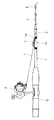
図1に示す本発明の一実施形態を採用したルアーフィッシング用の中通し竿は、先細り筒状の元竿1と、元竿1の先端側に並継形式で連結された先細り筒状の穂先竿2とを有している。元竿1の前端部には糸導入口1aが形成されている。元竿1の糸導入口1aの前後の部分には他の部分より厚肉の肉盛り部1bが形成されている。この肉盛り部1bを形成することで内外周を貫通する糸導入口1aにより曲げ強さが低下するのを防止している。この糸導入口1aから竿体内部に導入された釣り糸Lは、竿体の内部経路5を通って穂先竿2の先端開口に装着されたトップガイド6から導出される。元竿1の手元側にはグリップGを挟んでスピニングリール3が装着可能である。また、元竿1の竿先側には、リール3から釣り糸Lを糸導入口1aに案内する糸導入ガイド4が装着されている。
【0011】
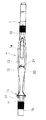
糸導入口1aが形成された元竿1の内部には、図2に示すように、ガイド筒7が嵌め込まれている。ガイド筒7は、合成樹脂製の円筒部材であり、後端が弾性体製の水止め中栓8により封止されている。ガイド筒7の周面には糸導入口1aに対向する開口7aが形成されている。ガイド筒7の前部にはリング装着溝7bが形成されており、そこにセラミック等からなる硬質リング9aが装着されている。リング装着溝7bに向かってガイド筒7の内壁は、先細り形状のテーパ面7cになっており、テーパ面7cにより釣り糸を竿体内部に通すのに使用する糸通し具30の先端30aが硬質リング9aに容易に案内される。
【0012】
穂先竿2の後端には尻栓18が着脱自在に装着されており、尻栓18の後端には硬質リング9bが嵌め込まれている。
【0013】
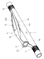
図3〜図5に示すように、糸導入ガイド4は、プレス加工等の塑性加工法によりステンレス鋼板等の金属板を所定の形状に打ち抜き湾曲させて得られたものである。糸導入ガイド4は、舌片状の前固定部10と、同様に舌片状の後固定部11と、前後の固定部10,11を連結する連結部12とを有している。固定部10,11はそれぞれ糸を元竿1に巻き付けることで元竿1に固定されている。連結部12は、前固定部10から滑らかに内方から外方に湾曲し、後固定部11の前方で折り曲げられたアーチ状に形成されている。
【0014】
また、図3から明らかなように、連結部12の軸方向中間部はその前後の部分に比較して徐々に幅が広くなっている。この糸導入ガイド4は、糸導入口1aの上方にアーチ状連結部12の内方湾曲部12aが位置するように元竿1に固定されている。この内方湾曲部12aの糸導入口1aの上方には、開口部13が形成されている。そして、アーチ状連結部12の折り曲げ部分で前方に傾斜したリール側(後方側)傾斜部12bに第1ガイド部15が設けられている。第1ガイド部15は、リール側傾斜部12bに形成された貫通孔16と、貫通孔16の開口縁部に装着されたセラミック等からなる硬質リング17とを有している。
【0015】
連結部12の幅広部の両側には、図4及び図5から明らかなように、補強リブ12cが形成されている。補強リブ12cは、連結部12の幅広部の両側を下方に折り曲げることで形成されており、この補強リブ12cにより連結部12の剛性が向上し、連結部12にものが当たっても変形しにくい。このため、硬質リング17が変形によりはずれにくい。
【0016】
開口部13の後縁には下方に折り曲げられて形成された中間支持部20が設けられている。中間支持部20には第2ガイド部21が設けられている。第2ガイド部21は、中間支持部20に形成された貫通孔22と、貫通孔22の開口縁部に装着されたセラミック等からなる硬質リング23とを有している。硬質リング23は、硬質リング17より内径が小さい。この中間支持部20は、ほぼ元竿1の軸に対して垂直に形成されている。この結果、第2ガイド部21は、前方に傾斜したリール側傾斜部12bに設けられた第1ガイド部15より釣り糸Lに対して傾斜して配置されている。
【0017】
この糸導入ガイド4を使用する場合は、リール3から繰り出された釣り糸をワイヤ等からなる糸通し具30に取り付け、糸通し具30の先端30aを第1及び第2ガイド部15,21に通した後、糸導入口1aに導く。このとき、図2に示すように、元竿1内部にガイド筒7を装着し、このガイド筒7にテーパ面7cを設けたので、糸通し具30の先端30aが容易に元竿1内の硬質リング9aに導かれる。糸導入口1aから竿内部に挿入された糸通し具は、竿内部の内部経路5を通して穂先側に導かれ、穂先竿2のトップガイド6から導出され、それを摘んで取り出すことで釣り糸Lが竿の内部経路5に挿通される。
【0018】
このような実施形態の構造では、硬質リング9aの手前側にテーパ面7cが設けられているので、糸通し具の先端が容易に硬質リング9aに案内され、糸通し具30を糸導入口1aから内部経路5に通しやすくなる。
【0019】
また、テーパ面7cと硬質リング9aとがガイド筒7に配置されるので、元竿1を細工することなく、糸通し具30を糸導入口1aから内部経路5に通しやすくなる。
【0020】
さらに、ガイド筒7の竿尻側の端部が中栓8により封止されるので、濡れた釣り糸により内部が水で濡れても水や砂等が中空体より竿尻側に回らない。
【0021】
〔他の実施形態〕
(a) 本発明はルアーフィッシング用の並継形式の中通し竿に限定されるものではなく、全ての用途形式の中通し竿に適用できる。
【0022】
(b) 糸通し具案内用のテーパ面を元竿に直接形成してもよい。
【0023】
【発明の効果】
本発明によれば、糸案内リングの手前側に糸通し具案内部が設けられているので、糸通し具の先端が容易に糸案内リングに案内され、糸通し具を糸導入口から内部経路に通しやすくなる。
【図面の簡単な説明】
【図1】 本発明の一実施形態が採用された中通し竿の側面図。
【図2】 その糸導入口付近の断面拡大図。
【図3】 糸導入ガイドの平面図。
【図4】 糸導入ガイドの断面図。
【図5】 糸導入ガイドの斜視図。
【符号の説明】
1 元竿
1a 糸導入口
3 リール
4 糸導入ガイド
5 内部経路
7 ガイド筒
7c テーパ面
8 中栓
9a 硬質リング
30 糸通し具[0001]
BACKGROUND OF THE INVENTION
The present invention relates to a fishing rod, and more particularly to a threading rod through which a fishing line is inserted using a threading tool.
[0002]
[Prior art]
The threading rod has an internal path through which the fishing line is inserted, and has a thread introduction port for introducing the fishing line into the internal path on the hand side, and a thread for leading the fishing line to the tip of the tip. Has outlet. A thread guide ring having an inner diameter smaller than that of the internal path is attached to the front end of the internal path in order to reduce the frictional resistance of the fishing line. In such a through rod, the fishing line from the reel is introduced into the internal path inside the rod through the yarn introduction port, and further led out to the outside from the yarn outlet port of the tip.
[0003]
In this type of threading rod, a threading tool is used to introduce the fishing line into the internal path through the thread introduction port and to take it out from the thread outlet port. The threader is composed of a wire formed by a plurality of strands. At the rear end of the wire, a thread stopper for locking the fishing line is provided. A cap is fixed to the tip of the wire to prevent the wire strand from spreading.
[0004]
When using such a threading tool to pass the fishing line through the threading rod, first, the fishing line is locked to the thread stopper of the threading tool. Next, the tip of the threader is inserted into the internal path through the thread guide ring from the thread introduction port of the proximal housing. Then, by pushing the threading tool, the threading tool is sent to the tip, and the tip of the threading tool is led out from the thread outlet port of the tip. Thereafter, the tip of the threading tool is pinched and pulled out, and the fishing line locked to the thread stopper is taken out from the thread outlet.
[0005]
[Problems to be solved by the invention]
The conventional threading rod having the above-described structure has a problem that it is difficult to pass the tip of the threader through the thread guide ring when the fishing line is set in the internal path using the threader. This is because the inner diameter of the thread guide ring is small, and therefore, when a threading tool is inserted from the thread introduction port provided on the outer peripheral surface, the tip portion of the thread guide ring is easily caught on the end face of the thread guide ring.
[0006]
The subject of this invention is making it easy to let a threading tool pass to an internal path | route from a thread | yarn introduction port.
[0007]
[Means for Solving the Problems]
The threading rod according to the first aspect of the present invention is a rod through which a fishing line is inserted using a threader, and includes a rod body, a thread introduction guide, a thread guide ring, a threading guide portion, and a hollow body. It has. The rod has a line introduction port for introducing a fishing line into the inside formed on the outer peripheral surface, and an internal path formed inside for inserting the fishing line. The yarn introduction guide has a tongue-like front fixing portion and a rear fixing portion that are fixed to the housing, and a connecting portion that connects the front fixing portion and the rear fixing portion and is located above the yarn introducing port, and a reel The fishing line from is guided to the line. The line guide ring is a ring that is arranged in the internal path and guides the fishing line introduced from the line introduction port to the internal path. The threading tool guide is provided inside the housing and is for guiding the tip of the threading tool introduced from the thread introduction port to the thread guide ring. The hollow body has a ring mounting portion provided on the inner periphery on the front end side for mounting the yarn guide ring, and an opening formed on the outer peripheral surface so as to face the yarn introducing port, and the yarn introducing port is formed. It is mounted inside the housing. The threading tool guide portion is formed behind the ring mounting portion on the inner peripheral surface of the hollow body, and has a tapered shape toward the ring mounting portion.
[0008]
In this structure, when the fishing line is set in the internal path using the threading tool, first, the fishing line is locked to the threading tool, and the tip of the threading tool is inserted from the thread introduction port. Then, the tip is guided by the threader guide portion, inserted through the thread guide ring, and inserted into the internal path. Then, the threading tool is pushed to lead out the tip from the tip, and the tip is picked to remove the fishing line from the tip. Here, since the threading tool guide portion is provided on the front side of the thread guide ring, the tip of the threading tool is easily guided by the thread guide ring, and the threading tool can be easily passed through the internal path from the thread introduction port. Become. In addition, since the threading tool guide portion and the thread guide ring are arranged in the hollow body, the threading tool can be easily passed from the thread introduction port to the internal path without crafting the casing.
[0009]
An internal thread according to a second aspect of the present invention is the collar according to the first aspect, further comprising an inner plug that seals the end of the hollow body on the buttock side. In this case, since the end portion of the hollow body on the buttock side is sealed, even if the inside is wet with water by the wet fishing line, water, sand or the like does not turn to the buttock side from the hollow body.
[0010]
DETAILED DESCRIPTION OF THE INVENTION
A lure fishing threading rod that employs an embodiment of the present invention shown in FIG. 1 is a tapered
[0011]
As shown in FIG. 2, a
[0012]
A
[0013]
As shown in FIGS. 3 to 5, the
[0014]
Further, as apparent from FIG. 3, the intermediate portion of the connecting
[0015]
As is apparent from FIGS. 4 and 5, reinforcing
[0016]
An
[0017]
When this
[0018]
In the structure of such an embodiment, since the tapered
[0019]
Moreover, since the
[0020]
Furthermore, since the end portion on the buttock side of the
[0021]
Other Embodiment
(A) The present invention is not limited to the relay rods for the lure fishing type, but can be applied to all rods for all types of use.
[0022]
(B) A taper surface for guiding the threader may be formed directly on the base.
[0023]
【The invention's effect】
According to the present invention, since the threading tool guide portion is provided on the front side of the thread guide ring, the tip of the threading tool is easily guided to the thread guide ring, and the threading tool is routed from the thread introduction port to the internal path. It becomes easy to pass through.
[Brief description of the drawings]
BRIEF DESCRIPTION OF DRAWINGS FIG. 1 is a side view of a threading rod in which an embodiment of the present invention is adopted.
FIG. 2 is an enlarged cross-sectional view of the vicinity of the yarn introduction port.
FIG. 3 is a plan view of a yarn introduction guide.
FIG. 4 is a cross-sectional view of a yarn introduction guide.
FIG. 5 is a perspective view of a yarn introduction guide.
[Explanation of symbols]
DESCRIPTION OF
Claims (2)
外周面に形成され前記釣り糸を内部に導入するための糸導入口と、内部に形成され前記釣り糸を挿通するための内部経路とを有する竿体と、
前記竿体に固定される舌片状の前固定部および後固定部と、前記前固定部および前記後固定部を連結し前記糸導入口の上方に位置する連結部とを有し、リールからの釣り糸を前記糸導入口に案内する糸導入ガイドと、
前記内部経路内に配置され、前記糸導入口から導入された釣り糸を前記内部経路に案内するための糸案内リングと、
前記竿体の内部に設けられ、前記糸導入口から導入された前記糸通し具の先端を前記糸案内リングに案内するための糸通し具案内部と、
前記糸案内リングを装着するために先端側内周に設けられたリング装着部と、前記糸導入口に対向可能に外周面に形成された開口とを有し、前記糸導入口が形成された竿体内部に装着された中空体と、
を備え、
前記糸通し具案内部は、前記中空体の内周面の前記リング装着部後方に形成されており、前記リング装着部に向かって先細り形状となっている、
中通し竿。A threading rod through which the fishing line is inserted using a threader,
A housing having a thread introduction port formed on the outer peripheral surface for introducing the fishing line therein, and an internal path formed inside for inserting the fishing line;
A tongue-shaped front fixing portion and a rear fixing portion that are fixed to the housing, and a connecting portion that connects the front fixing portion and the rear fixing portion and is located above the yarn introduction port, A thread introduction guide for guiding the fishing line to the thread introduction port;
A line guide ring that is arranged in the internal path and guides the fishing line introduced from the line introduction port to the internal path;
A threading tool guide for guiding the tip of the threading tool introduced from the thread introduction port to the thread guide ring, which is provided inside the housing;
A ring mounting portion provided on the inner periphery on the front end side for mounting the yarn guide ring, and an opening formed on the outer peripheral surface so as to be opposed to the yarn introduction port, and the yarn introduction port was formed A hollow body mounted inside the housing;
With
The threader guide portion is formed behind the ring mounting portion on the inner peripheral surface of the hollow body, and has a tapered shape toward the ring mounting portion.
A penetrating bowl.
請求項1に記載の中通し竿。Further comprising an inner plug for sealing the end of the hollow body on the buttock side,
The continuous thread according to claim 1.
Priority Applications (1)
| Application Number | Priority Date | Filing Date | Title |
|---|---|---|---|
| JP23606096A JP3752322B2 (en) | 1996-09-06 | 1996-09-06 | Punch |
Applications Claiming Priority (1)
| Application Number | Priority Date | Filing Date | Title |
|---|---|---|---|
| JP23606096A JP3752322B2 (en) | 1996-09-06 | 1996-09-06 | Punch |
Publications (2)
| Publication Number | Publication Date |
|---|---|
| JPH1075690A JPH1075690A (en) | 1998-03-24 |
| JP3752322B2 true JP3752322B2 (en) | 2006-03-08 |
Family
ID=16995146
Family Applications (1)
| Application Number | Title | Priority Date | Filing Date |
|---|---|---|---|
| JP23606096A Expired - Lifetime JP3752322B2 (en) | 1996-09-06 | 1996-09-06 | Punch |
Country Status (1)
| Country | Link |
|---|---|
| JP (1) | JP3752322B2 (en) |
Families Citing this family (1)
| Publication number | Priority date | Publication date | Assignee | Title |
|---|---|---|---|---|
| JP4906151B2 (en) * | 2007-11-30 | 2012-03-28 | グローブライド株式会社 | Joint type fishing rod |
-
1996
- 1996-09-06 JP JP23606096A patent/JP3752322B2/en not_active Expired - Lifetime
Also Published As
| Publication number | Publication date |
|---|---|
| JPH1075690A (en) | 1998-03-24 |
Similar Documents
| Publication | Publication Date | Title |
|---|---|---|
| JP3752322B2 (en) | Punch | |
| JP3770349B2 (en) | Thread introduction guide for threading thread | |
| US5930940A (en) | Line introduction guide for pass-through fishing rod | |
| JP3777238B2 (en) | Thread introduction guide for threading thread | |
| JP2004089055A (en) | Fishing line guide and spinning rod | |
| JP4547566B2 (en) | fishing rod | |
| JP3688787B2 (en) | Punch | |
| JP4179429B2 (en) | Threader | |
| JPH11137145A (en) | Threading tool for internally threaded rod | |
| JP4392727B2 (en) | Punch | |
| JP7119156B1 (en) | fishing rod | |
| JP4420366B2 (en) | Punch | |
| JP2001045922A (en) | Internally threaded fishing rod | |
| CN218923363U (en) | Device is broken in special use thorax or peritoneal hydrops fibre separation | |
| JP3708491B2 (en) | Fishhook with thread | |
| JP4024663B2 (en) | fishing rod | |
| JP4108209B2 (en) | Threader | |
| JP4036405B2 (en) | Top cover | |
| JP4040771B2 (en) | fishing rod | |
| JPS6132933Y2 (en) | ||
| JPH0125551Y2 (en) | ||
| JP3819088B2 (en) | Punch | |
| JPH0246290Y2 (en) | ||
| JP3657348B2 (en) | Through hole with spout | |
| JP3111281U (en) | fishing rod |
Legal Events
| Date | Code | Title | Description |
|---|---|---|---|
| A977 | Report on retrieval |
Free format text: JAPANESE INTERMEDIATE CODE: A971007 Effective date: 20050513 |
|
| A131 | Notification of reasons for refusal |
Free format text: JAPANESE INTERMEDIATE CODE: A131 Effective date: 20050517 |
|
| A521 | Written amendment |
Free format text: JAPANESE INTERMEDIATE CODE: A523 Effective date: 20050615 |
|
| TRDD | Decision of grant or rejection written | ||
| A01 | Written decision to grant a patent or to grant a registration (utility model) |
Free format text: JAPANESE INTERMEDIATE CODE: A01 Effective date: 20051122 |
|
| A61 | First payment of annual fees (during grant procedure) |
Free format text: JAPANESE INTERMEDIATE CODE: A61 Effective date: 20051212 |
|
| R150 | Certificate of patent or registration of utility model |
Free format text: JAPANESE INTERMEDIATE CODE: R150 |
|
| FPAY | Renewal fee payment (event date is renewal date of database) |
Free format text: PAYMENT UNTIL: 20081216 Year of fee payment: 3 |
|
| FPAY | Renewal fee payment (event date is renewal date of database) |
Free format text: PAYMENT UNTIL: 20091216 Year of fee payment: 4 |
|
| FPAY | Renewal fee payment (event date is renewal date of database) |
Free format text: PAYMENT UNTIL: 20091216 Year of fee payment: 4 |
|
| FPAY | Renewal fee payment (event date is renewal date of database) |
Free format text: PAYMENT UNTIL: 20101216 Year of fee payment: 5 |
|
| FPAY | Renewal fee payment (event date is renewal date of database) |
Free format text: PAYMENT UNTIL: 20101216 Year of fee payment: 5 |
|
| FPAY | Renewal fee payment (event date is renewal date of database) |
Free format text: PAYMENT UNTIL: 20111216 Year of fee payment: 6 |
|
| FPAY | Renewal fee payment (event date is renewal date of database) |
Free format text: PAYMENT UNTIL: 20111216 Year of fee payment: 6 |
|
| FPAY | Renewal fee payment (event date is renewal date of database) |
Free format text: PAYMENT UNTIL: 20121216 Year of fee payment: 7 |
|
| FPAY | Renewal fee payment (event date is renewal date of database) |
Free format text: PAYMENT UNTIL: 20121216 Year of fee payment: 7 |
|
| FPAY | Renewal fee payment (event date is renewal date of database) |
Free format text: PAYMENT UNTIL: 20131216 Year of fee payment: 8 |
|
| R250 | Receipt of annual fees |
Free format text: JAPANESE INTERMEDIATE CODE: R250 |
|
| R250 | Receipt of annual fees |
Free format text: JAPANESE INTERMEDIATE CODE: R250 |
|
| EXPY | Cancellation because of completion of term |