JP3752011B2 - Vaporizer - Google Patents
Vaporizer Download PDFInfo
- Publication number
- JP3752011B2 JP3752011B2 JP08102396A JP8102396A JP3752011B2 JP 3752011 B2 JP3752011 B2 JP 3752011B2 JP 08102396 A JP08102396 A JP 08102396A JP 8102396 A JP8102396 A JP 8102396A JP 3752011 B2 JP3752011 B2 JP 3752011B2
- Authority
- JP
- Japan
- Prior art keywords
- piston valve
- intake passage
- needle
- passage
- fuel
- Prior art date
- Legal status (The legal status is an assumption and is not a legal conclusion. Google has not performed a legal analysis and makes no representation as to the accuracy of the status listed.)
- Expired - Fee Related
Links
Images
Landscapes
- Control Of The Air-Fuel Ratio Of Carburetors (AREA)
Description
【0001】
【発明の属する技術分野】
本発明は、例えば二輪車のエンジンに搭載され、ピストンバルブを有する気化器に関し、特にそのピストンバルブの改良に関する。
【0002】
【従来の技術】
ピストンバルブを有する気化器は、ピストンバルブにアクセルケーブルが連結され、ピストンバルブがエンジンへ供給される空気量を制御するスロットル弁の機能を有するタイプと、ピストンバルブの下流にスロットル弁としてのバタフライ弁を有し、ピストンバルブの吸気通路に臨む側とは反対側にダイアフラム室あるいはピストン室を設け、このダイアフラム室あるいはピストン室へ吸気通路の負圧を作用させてピストンバルブを昇降させるタイプとがある。
【0003】
いずれのタイプでも、ピストンバルブには下方に突出するニードルが設けられ、ニードルの先端はフロート室内に連通する出口にニードルジェットを有する燃料通路(メインノズル)内に挿入されている。すなわち、ニードルの高さ位置に応じて燃料通路の流路面積が変化し、フロート室に貯溜された燃料が燃料通路を通ってニードルとニードルジェットの隙間で計量され、吸気通路内に導かれる。この時、燃料の一部は表面張力によりニードルの表面を伝わってピストンバルブの底部まで上昇し、ピストンバルブの後流の影響によって飛散する。
【0004】
【発明が解決しようとする課題】
このようにして飛散した燃料は吸気通路の壁面に付着しやすく、壁面に付着した燃料は壁面を伝わる流れとなるため、空気流に乗って流れる燃料に比べてエンジンの燃焼室へ到達するのが遅くなる。したがって燃料供給の応答遅れが生じ、加速運転時の初期の段階において空燃比がリーン状態となり、エンジンの応答性を高めることに障害となっていた。
【0005】
本発明は、応答性に優れた気化器を提供することを目的とする。
【0006】
【課題を解決するための手段】
本発明に係る気化器は、吸気通路と、この吸気通路内に燃料を供給するための燃料通路と、その出口にニードルジェットが形成された気化器本体と、この気化器本体に昇降自在に支持され、吸気通路内に突出してこの吸気通路の流路面積を変化させるピストンバルブと、このピストンバルブに連結され、ニードルジェット内に挿入されるニードルとを備え、ピストンバルブの吸気通路の下流側に臨む背面は、ニードルに近接した部位が最も上流側に位置し、ピストンの昇降方向に沿って延びる凹状の湾曲面であり、この湾曲面はピストンバルブの下端まで達し、ピストンバルブの吸気通路の上流側に臨む前面は、平面または凸面であることを特徴としている。
【0007】
このようにピストンの背面を凹状に湾曲させたことにより、ピストンの背面より出た空気流は吸気通路の中央へ収束し、これにより燃料の壁面への付着が抑制される。また、ピストンバルブの吸気通路の上流側に臨む前面が平面または凸面であるため、ピストンバルブの中央部に、このピストンバルブの戻りスプリングを配設することが可能となり、ピストンバルブの戻りをスムーズに行うことができる。
【0008】
ピストンバルブの昇降方向に垂直な平面でピストンバルブを切断して得られる断面形状は、ピストンバルブの略全高にわたって同じ形状である。この断面形状は、ピストンバルブの全高にわたって同じ形状であってもよい。この断面形状は、長円を円弧状に湾曲させて成るものであってもよい。ピストンバルブの略全高にわたって同じ形状であることに代えて、凹状の湾曲面がピストンバルブの下端より一定の限られた範囲に形成されていてもよい。
【0009】
ピストンバルブの吸気通路の下流側に臨む背面の凹状湾曲部の断面形状は、ニードルに近接した部位を最も上流側とする円弧から成るものであっても、またニードルに近接した部位で交差する2つの線分から成るものであってもよい。
【0010】
【発明の実施の形態】
以下、本発明の実施の形態を図面を参照して説明する。
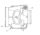
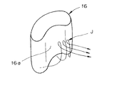
図1は本発明の第1の実施形態に係る、ピストンバルブがスロットル弁の機能を果たすタイプのピストンバルブを有する気化器の断面図、図2は図1の気化器の本体を示す平面図、図3は図1のピストンバルブを示す斜視図である。
【0011】
図1に示すように、気化器本体11の内部には水平方向に延びる吸気通路12が形成されている。吸気通路12の上方には摺動室13が、また吸気通路12の下方には燃料通路18が形成され、燃料通路18の吸気通路12への開口端部にはニードルジェット20が設けられている。これら摺動室13と燃料通路18は、吸気通路12に直交している。摺動室13には、ピストンバルブ16が摺動自在すなわち昇降自在に支持されている。気化器本体11のピストンバルブ16の下方にはフロート室17が配設されており、フロート室17に貯溜された燃料は燃料通路18を通って吸気通路12に導かれる。ピストンバルブ16の下面にはニードル19が連結されており、燃料通路18を通る燃料の流量は、ニードルジェット20に対するニードル19の挿入度合いによって調整される。
【0012】
気化器本体11の入口部には、外部からの空気を取り込むラッパ型のエアファンネル14が固定され、摺動室13の上部にはカバー15が設けられている。カバー15とピストンバルブ16の間にはバネ21が設けられ、ピストンバルブ16は吸気通路12を遮断する方向に常時付勢されている。カバー15に取り付けられた案内ボルト22の内部には、このボルト22の長手方向に延びる貫通孔(図示せず)が形成されている。アクセル機構に連結されたワイヤ(図示せず)は、案内ボルト22の貫通孔を通り、ピストンバルブ16に連結されている。すなわち、アクセル機構を操作すると、ワイヤを介してピストンバルブ16がバネ21に抗して上昇し、吸気通路12内における突出量が変化して吸気通路12の流路面積が変化する。
【0013】
図2は、気化器本体11からカバー15を除いた状態を示している。この図に示すように、摺動室13は上方から見るとまゆ形、すなわち長円を円弧状に湾曲させた形状を呈しており、エアファンネル14側が突出し、その反対側が凹陥している。吸気通路12の底部に形成された燃料通路18は、摺動室13の略中央に対応している。
【0014】
図3に示すようにピストンバルブ16は、摺動室13と同様に、上方から見ると長円を円弧状に湾曲させた形状を呈し、ニードル19は燃料通路18に対応した部位に連結されている。すなわちピストンバルブ16の吸気通路12の下流側に臨む背面16aは、ニードル19に近接した部位が最も上流側に位置するように凹状に湾曲し、またピストンバルブ16の吸気通路12の上流側に臨む前面16bは凸面である。ピストンバルブ16は摺動室13内において昇降するため、ピストンバルブ16の昇降方向に垂直な平面でこのピストンバルブ16を切断して得られる断面形状は、ピストンバルブ16の略全高にわたって同じ形状である。
【0015】
図4〜図6を参照して本実施形態の作用を説明する。
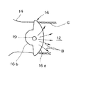
図示しないアクセル機構を操作することによってピストンバルブ16すなわちニードル19が上昇すると、吸気通路12とニードルジェット20の開口面積が増大し、吸気通路12内に供給される燃料量が増加する。フロート室17に貯溜された燃料は燃料通路18およびニードルジェット20を通り、吸気通路12内へ吸い出される。その燃料の一部は表面張力によりニードル19の表面を伝わってピストンバルブ16の底面16cに達する(符号F)。エアファンネル14から流入した空気は、ピストンバルブ16の底面16cの下方を通って背面16a側へ流れる。この時ニードル19の近傍を通る空気流は、図5および図6の矢印Aで示すように、ピストンバルブ16の背面16a側において、凹部つまり吸気通路12の中央部に発生する渦Jに引かれて、吸気通路12の壁面の方向に拡散せず、実質的に吸気通路12の軸心方向に流れる。したがって、燃料は吸気通路12の壁面には付着しにくく、エンジンのシリンダ室に迅速に供給される。すなわち、燃料供給の応答性は高く、エンジンの加速性が向上する。
【0016】
これに対し、図7に示す比較例では、ニードル19の近傍を通る空気流は矢印Bで示すように、ピストンバルブ16の背面16a側において、渦は吸気通路12の中央よりむしろ側壁付近に強く発生するため、吸気通路12の壁面の方向に拡散する。このため、フロート室17からニードルジェット20内に供給された燃料の一部Gは吸気通路12の壁面に付着し、したがって、エンジンのシリンダ室への供給が遅れ、エンジンの加速性を十分に高めることは困難である。
【0017】
また本実施形態は、摺動室13の形状が単純であるため、エンドミル等によって加工でき、しかも単一のカッタを用いて加工できる。さらにピストンバルブ16は摺動室13の内壁によって直接摺動自在に支持されており、ピストンバルブ16を案内するためのガイド部材を摺動室13内に設ける必要がないため、この摺動弁を有する気化器は、構成が簡単で、安価に製造することができる。
【0018】
図1に示すようなピストンバルブがスロットル弁の機能を果たすタイプでは、ピストンバルブ全閉時にピストンバルブ外周および底面の隙間を通過してエンジンへ吸収される空気量を極力少なくする必要があり、そのためにはピストンバルブの昇降方向に垂直な平面でピストンバルブを切断して得られる断面形状は図3に示すようにピストンバルブの全高にわたって同じ形状であることが好ましい。摺動室13も図2に示すようにピストンバルブと同じ形状となる。
【0019】
これに対し、ピストンバルブの高さ方向において断面形状が異なる構成も可能であり、このような構成の例として、図8〜図10に本発明の第2の実施形態の気化器を示す。この気化器は、ピストンバルブ16が吸気通路12に臨む側と反対側にダイアフラム装置40を設け、ダイアフラム装置40内に設けられたダイアフラム41にピストンバルブ16を連結するとともに、ダイアフラム41にピストンバルブ16を連結し、ダイアフラム室42へ吸気通路12の負圧を導入し、その負圧でピストンバルブ16を開閉するタイプである。ピストンバルブ16はダイアフラム装置40の摺動壁43によって、昇降方向に摺動自在に支持されている。
【0020】
このタイプではピストンバルブ16は吸気通路12を全閉させないため、図9および図10から理解されるように、ピストンバルブ16を昇降方向に垂直な平面で切断して得られる断面形状は、摺動壁面43に摺接する部分16dと下端部16eとで異なっていてもよい。すなわち摺接部分16dの背面は略平面であるが、下端部16eの背面16aは凹状に湾曲している。この背面16aの湾曲面の断面形状は、図9の例ではピストンバルブ16の昇降方向に沿って同じであり、図10の例ではピストンバルブ16の昇降方向に沿って変化し、上方ほど湾曲面は小さくなっている。
【0021】
図11は、第3の実施形態におけるピストンバルブ31を水平面で切断した断面形状を示す図である。この実施形態におけるピストンバルブ31の断面形状は、その両端の半円31sをニードル19に向かって、吸気通路12の長手方向に対して例えば約70度の角度をなす線に沿って直線的に移動させることにより形成される外形を有している。すなわち背面31aの断面形状はニードル19に近接した部位で交差する2つの線分から成り、背面31aは2つの平面31tによって構成される。また前面31bは2つの平面31uと円弧状面31vによって構成される。
【0022】
図12は、第4の実施形態におけるピストンバルブ32を水平面で切断した断面形状を示す図である。この実施形態では、ピストンバルブ32の背面32aの断面形状はニードル19に近接した部位で交差する2つの線分から成る。すなわち背面32aは2つの平面によって構成される。一方、ピストンバルブ32の前面32bは平面であり、吸気通路12の軸心方向にほぼ垂直である。
【0023】
図13は第5の実施形態におけるピストンバルブ33を水平面で切断した断面形状を示す図である。この実施形態では、ピストンバルブ33の背面33aの断面形状は湾曲し、例えば円弧状である。すなわち背面33aは円筒面状に湾曲しており、一方前面33bは吸気通路12の軸心方向にほぼ垂直な平面である。
【0024】
図14は、第6の実施形態におけるピストンバルブ34を水平面で切断した断面形状を示す図である。ピストンバルブ34の背面34aと前面34bは共に、2つの平面によって構成されている。背面34aの2つの平面のなす角は、前面34bのなす角よりも小さい。
【0025】
図15は、第7の実施形態におけるピストンバルブ35を水平面で切断した断面形状を示す図である。ピストンバルブ35の背面35aと前面35bは共に、湾曲面によって構成されている。これらの湾曲面の曲率は、背面35aの方が前面35bよりも小さい。
【0026】
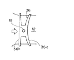
図16は、第8の実施形態におけるピストンバルブ36を水平面で切断した断面形状を示す図である。この実施形態は図13の第5の実施形態と同様に、ピストンバルブ36の背面36aは円筒面状に湾曲し、前面36bは吸気通路12の軸心方向にほぼ垂直な平面である。
【0027】
図17は、第9の実施形態におけるピストンバルブ37を水平面で切断した断面形状を示す図である。この実施形態では、ピストンバルブ37の断面形状は、略円形を有し、背面37aは円筒面状に湾曲している。
【0028】
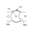
図18は、第10の実施形態におけるピストンバルブ38を水平面で切断した断面形状を示す図である。この実施形態では、ピストンバルブ38の断面形状は、略円形を有し、背面38aは図14の第8の実施形態と同様に、所定の角度で交差する2つの平面から成る。
【0029】
第2〜第10の実施形態によっても、第1の実施形態と同様な効果が得られる。
【0030】
【発明の効果】
以上のように本発明によれば、気化器の応答性が向上し、エンジンの加速性が高められるという効果が得られる。
【図面の簡単な説明】
【図1】本発明の第1の実施形態に係る気化器の断面図である。
【図2】図1の気化器の本体を示す平面図である。
【図3】ピストンバルブを示す斜視図である。
【図4】第1の実施形態におけるピストンバルブが開放している状態を示す断面図である。
【図5】第1の実施形態におけるピストンバルブのニードルの近傍の空気流を示す図である。
【図6】図5と同じ状態を示す斜視図である。
【図7】比較例におけるピストンバルブのニードルの近傍の空気流を示す図である。
【図8】第2の実施形態に係る気化器の断面図である。
【図9】第2の実施形態におけるピストンバルブの一例を示す斜視図である。
【図10】第2の実施形態におけるピストンバルブの他の例を示す斜視図である。
【図11】第3の実施形態におけるピストンバルブの断面形状を示す図である。
【図12】第4の実施形態におけるピストンバルブの断面形状を示す図である。
【図13】第5の実施形態におけるピストンバルブの断面形状を示す図である。
【図14】第6の実施形態におけるピストンバルブの断面形状を示す図である。
【図15】第7の実施形態におけるピストンバルブの断面形状を示す図である。
【図16】第8の実施形態におけるピストンバルブの断面形状を示す図である。
【図17】第9の実施形態におけるピストンバルブの断面形状を示す図である。
【図18】第10の実施形態におけるピストンバルブの断面形状を示す図である。
【符号の説明】
11 気化器本体
12 吸気通路
16、31、32、33、34、35、36、37、38 ピストンバルブ
16a、31a、32a、33a、34a、35a、36a、
37a、38a 背面
16b、31b、32b、33b、34b、35b、36b、
37b、38b 前面
18 燃料通路
19 ニードル[0001]
BACKGROUND OF THE INVENTION
The present invention relates to a carburetor mounted on, for example, a motorcycle engine and having a piston valve, and more particularly to an improvement of the piston valve.
[0002]
[Prior art]
A carburetor having a piston valve has a throttle valve function in which an accelerator cable is connected to the piston valve and the piston valve controls the amount of air supplied to the engine, and a butterfly valve as a throttle valve downstream of the piston valve There is a type in which a diaphragm chamber or a piston chamber is provided on the side opposite to the side facing the intake passage of the piston valve, and the piston valve is moved up and down by applying a negative pressure of the intake passage to the diaphragm chamber or the piston chamber. .
[0003]
In either type, the piston valve is provided with a needle protruding downward, and the tip of the needle is inserted into a fuel passage (main nozzle) having a needle jet at the outlet communicating with the float chamber. That is, the flow passage area of the fuel passage changes according to the height position of the needle, and the fuel stored in the float chamber passes through the fuel passage and is measured in the gap between the needle and the needle jet and guided into the intake passage. At this time, part of the fuel travels along the surface of the needle due to surface tension, rises to the bottom of the piston valve, and scatters due to the influence of the wake of the piston valve.
[0004]
[Problems to be solved by the invention]
The fuel scattered in this way easily adheres to the wall surface of the intake passage, and the fuel attached to the wall surface flows through the wall surface, so that it reaches the combustion chamber of the engine as compared to the fuel flowing on the air flow. Become slow. Accordingly, a delay in the response of fuel supply occurs, and the air-fuel ratio becomes lean at an early stage during acceleration operation, which is an obstacle to improving the response of the engine.
[0005]
An object of this invention is to provide the vaporizer excellent in the responsiveness.
[0006]
[Means for Solving the Problems]
The carburetor according to the present invention includes an intake passage, a fuel passage for supplying fuel into the intake passage, a carburetor main body having a needle jet formed at an outlet thereof, and a carburetor main body that can be moved up and down. A piston valve that protrudes into the intake passage and changes the flow passage area of the intake passage, and a needle that is connected to the piston valve and inserted into the needle jet, and is provided downstream of the intake passage of the piston valve. The rear surface facing the needle is a concave curved surface that is located on the most upstream side in the vicinity of the needle, and extends along the direction of raising and lowering the piston. This curved surface reaches the lower end of the piston valve and is located upstream of the intake passage of the piston valve. The front surface facing the side is a flat surface or a convex surface.
[0007]
Thus, by curving the back surface of the piston in a concave shape, the air flow coming out from the back surface of the piston converges to the center of the intake passage, thereby suppressing the adhesion of fuel to the wall surface. In addition, since the front surface facing the upstream side of the intake passage of the piston valve is a flat surface or a convex surface, a return spring of the piston valve can be arranged at the center of the piston valve, so that the piston valve can be returned smoothly. It can be carried out.
[0008]
The cross-sectional shape obtained by cutting the piston valve along a plane perpendicular to the lifting / lowering direction of the piston valve is the same shape over substantially the entire height of the piston valve. This cross-sectional shape may be the same over the entire height of the piston valve. This cross-sectional shape may be formed by bending an ellipse into an arc shape. Instead of having the same shape over substantially the entire height of the piston valve, the concave curved surface may be formed in a certain limited range from the lower end of the piston valve.
[0009]
The cross-sectional shape of the concave curved portion on the back surface facing the downstream side of the intake passage of the piston valve may be an arc having a portion closest to the needle as the most upstream side, or intersects at a portion close to the needle. It may consist of two line segments.
[0010]
DETAILED DESCRIPTION OF THE INVENTION
Hereinafter, embodiments of the present invention will be described with reference to the drawings.
FIG. 1 is a cross-sectional view of a carburetor having a piston valve in which the piston valve functions as a throttle valve according to the first embodiment of the present invention, and FIG. 2 is a plan view showing a main body of the carburetor of FIG. FIG. 3 is a perspective view showing the piston valve of FIG.
[0011]
As shown in FIG. 1, an
[0012]
A trumpet
[0013]
FIG. 2 shows a state where the
[0014]
As shown in FIG. 3, like the
[0015]
The operation of the present embodiment will be described with reference to FIGS.
When the
[0016]
On the other hand, in the comparative example shown in FIG. 7, the air flow passing through the vicinity of the
[0017]
Further, in this embodiment, since the shape of the sliding
[0018]
In the type in which the piston valve as shown in FIG. 1 functions as a throttle valve, it is necessary to minimize the amount of air that is absorbed into the engine through the clearance between the outer periphery and bottom surface of the piston valve when the piston valve is fully closed. The sectional shape obtained by cutting the piston valve along a plane perpendicular to the elevation direction of the piston valve is preferably the same shape over the entire height of the piston valve as shown in FIG. The sliding
[0019]
On the other hand, the structure from which cross-sectional shape differs in the height direction of a piston valve is also possible, and the vaporizer | carburetor of the 2nd Embodiment of this invention is shown in FIGS. 8-10 as an example of such a structure. In this carburetor, a
[0020]
Since the
[0021]
FIG. 11 is a diagram illustrating a cross-sectional shape of the
[0022]
FIG. 12 is a view showing a cross-sectional shape of the
[0023]
FIG. 13 is a view showing a cross-sectional shape of the
[0024]
FIG. 14 is a view showing a cross-sectional shape of the
[0025]
FIG. 15 is a view showing a cross-sectional shape of the
[0026]
FIG. 16 is a diagram illustrating a cross-sectional shape of the
[0027]
FIG. 17 is a diagram illustrating a cross-sectional shape of the
[0028]
FIG. 18 is a view showing a cross-sectional shape of the
[0029]
According to the second to tenth embodiments, the same effects as those of the first embodiment can be obtained.
[0030]
【The invention's effect】
As described above, according to the present invention, it is possible to improve the responsiveness of the carburetor and increase the acceleration of the engine.
[Brief description of the drawings]
FIG. 1 is a cross-sectional view of a vaporizer according to a first embodiment of the present invention.
FIG. 2 is a plan view showing a main body of the vaporizer of FIG. 1;
FIG. 3 is a perspective view showing a piston valve.
FIG. 4 is a cross-sectional view showing a state in which the piston valve in the first embodiment is open.
FIG. 5 is a view showing an air flow in the vicinity of the needle of the piston valve in the first embodiment.
6 is a perspective view showing the same state as FIG. 5. FIG.
FIG. 7 is a diagram showing an air flow in the vicinity of a needle of a piston valve in a comparative example.
FIG. 8 is a cross-sectional view of a vaporizer according to a second embodiment.
FIG. 9 is a perspective view showing an example of a piston valve in the second embodiment.
FIG. 10 is a perspective view showing another example of the piston valve in the second embodiment.
FIG. 11 is a diagram showing a cross-sectional shape of a piston valve in a third embodiment.
FIG. 12 is a diagram showing a cross-sectional shape of a piston valve in a fourth embodiment.
FIG. 13 is a diagram showing a cross-sectional shape of a piston valve in a fifth embodiment.
FIG. 14 is a diagram showing a cross-sectional shape of a piston valve in a sixth embodiment.
FIG. 15 is a view showing a cross-sectional shape of a piston valve in a seventh embodiment.
FIG. 16 is a view showing a cross-sectional shape of a piston valve in an eighth embodiment.
FIG. 17 is a view showing a cross-sectional shape of a piston valve in a ninth embodiment.
FIG. 18 is a diagram showing a cross-sectional shape of a piston valve in a tenth embodiment.
[Explanation of symbols]
11
37a,
37b,
Claims (5)
この気化器本体に昇降自在に支持され、前記吸気通路内に突出してこの吸気通路の流路面積を変化させるピストンバルブと、
このピストンバルブに連結され、前記燃料通路の吸気通路内への開口部に設けたニードルジェット内に挿入され、このニードルジェットとともに形成される環状の開口面積を変化させるニードルとを備え、
前記ピストンバルブの断面形状が、長円を円弧状に湾曲させて成り、前記ピストンバルブの前記吸気通路の下流側に臨む背面は、前記ニードルに近接した部位が最も上流側に位置し、ピストンバルブの上昇方向に沿って延びる凹状の湾曲面であり、この湾曲面は前記ピストンバルブの下端まで達し、前記ピストンバルブの前記吸気通路の上流側に臨む前面は凸面である
ことを特徴とする気化器。A carburetor body in which an intake passage and a fuel passage for supplying fuel into the intake passage are formed;
A piston valve that is supported by the carburetor body so as to be movable up and down, protrudes into the intake passage, and changes the flow passage area of the intake passage;
A needle valve connected to the piston valve, inserted into a needle jet provided in an opening portion of the fuel passage into the intake passage, and an annular opening area formed together with the needle jet;
The cross-sectional shape of the piston valve is formed by curving an ellipse in an arc shape, and the back surface of the piston valve facing the downstream side of the intake passage is located closest to the needle on the most upstream side. A carburetor characterized in that it is a concave curved surface that extends along the rising direction of the piston valve, the curved surface reaches the lower end of the piston valve, and the front surface of the piston valve facing the upstream side of the intake passage is a convex surface. .
この気化器本体に昇降自在に支持され、前記吸気通路内に突出してこの吸気通路の流路面積を変化させるピストンバルブと、A piston valve that is supported by the carburetor body so as to be movable up and down, protrudes into the intake passage, and changes the flow passage area of the intake passage;
このピストンバルブに連結され、前記燃料通路の吸気通路内への開口部に設けたニードルジェット内に挿入され、このニードルジェットとともに形成される環状の開口面積を変化させるニードルとを備え、A needle valve connected to the piston valve, inserted into a needle jet provided in an opening portion of the fuel passage into the intake passage, and an annular opening area formed together with the needle jet;
前記ピストンバルブの前記吸気通路の下流側に臨む背面は、前記ニードルに近接した部位が最も上流側に位置し、ピストンバルブの上昇方向に沿って延びる凹状の湾曲面であり、この湾曲面は前記ピストンバルブの下端より一定の限られた範囲に形成され、前記ピストンバルブの前記吸気通路の上流側に臨む前面は凸面であるThe back surface of the piston valve facing the downstream side of the intake passage is a concave curved surface that is located on the most upstream side in the vicinity of the needle and extends along the upward direction of the piston valve. A front surface facing the upstream side of the intake passage of the piston valve is a convex surface formed in a certain limited range from the lower end of the piston valve.
ことを特徴とする気化器。A vaporizer characterized by that.
Priority Applications (1)
| Application Number | Priority Date | Filing Date | Title |
|---|---|---|---|
| JP08102396A JP3752011B2 (en) | 1996-03-08 | 1996-03-08 | Vaporizer |
Applications Claiming Priority (1)
| Application Number | Priority Date | Filing Date | Title |
|---|---|---|---|
| JP08102396A JP3752011B2 (en) | 1996-03-08 | 1996-03-08 | Vaporizer |
Publications (2)
| Publication Number | Publication Date |
|---|---|
| JPH09242613A JPH09242613A (en) | 1997-09-16 |
| JP3752011B2 true JP3752011B2 (en) | 2006-03-08 |
Family
ID=13734891
Family Applications (1)
| Application Number | Title | Priority Date | Filing Date |
|---|---|---|---|
| JP08102396A Expired - Fee Related JP3752011B2 (en) | 1996-03-08 | 1996-03-08 | Vaporizer |
Country Status (1)
| Country | Link |
|---|---|
| JP (1) | JP3752011B2 (en) |
-
1996
- 1996-03-08 JP JP08102396A patent/JP3752011B2/en not_active Expired - Fee Related
Also Published As
| Publication number | Publication date |
|---|---|
| JPH09242613A (en) | 1997-09-16 |
Similar Documents
| Publication | Publication Date | Title |
|---|---|---|
| JPS6125894B2 (en) | ||
| JPS5922046B2 (en) | Internal combustion engine intake system | |
| JPS6238533B2 (en) | ||
| JP3752011B2 (en) | Vaporizer | |
| JPS6236139B2 (en) | ||
| JPH0921354A (en) | Engine intake system | |
| JPH0942062A (en) | Sliding valve carburetor | |
| US4485774A (en) | Helically-shaped intake port of an internal-combustion engine | |
| JPS5915659A (en) | Variable venturi type carbureter | |
| JPH0236926Y2 (en) | ||
| JP2714760B2 (en) | Negative pressure operated valve in constant vacuum vaporizer | |
| JPS6233094Y2 (en) | ||
| JPH07279771A (en) | Sliding valve carburetor | |
| JPH10252563A (en) | Variable venturi carburetor | |
| JPS6238528B2 (en) | ||
| JPS6238531B2 (en) | ||
| JPS6181565A (en) | Sliding throttle valve type carburetor | |
| US6840509B2 (en) | Carburetor for an internal combustion engine | |
| JPS6229624Y2 (en) | ||
| JPS6236138B2 (en) | ||
| JPS58113563A (en) | Variable venturi type carburetor | |
| JPS6243061B2 (en) | ||
| JPS6238535B2 (en) | ||
| JPS6220691Y2 (en) | ||
| JPS6335166Y2 (en) |
Legal Events
| Date | Code | Title | Description |
|---|---|---|---|
| A977 | Report on retrieval |
Free format text: JAPANESE INTERMEDIATE CODE: A971007 Effective date: 20040820 |
|
| A131 | Notification of reasons for refusal |
Free format text: JAPANESE INTERMEDIATE CODE: A131 Effective date: 20040824 |
|
| A521 | Written amendment |
Free format text: JAPANESE INTERMEDIATE CODE: A523 Effective date: 20041005 |
|
| A521 | Written amendment |
Free format text: JAPANESE INTERMEDIATE CODE: A523 Effective date: 20041014 |
|
| A131 | Notification of reasons for refusal |
Free format text: JAPANESE INTERMEDIATE CODE: A131 Effective date: 20050304 |
|
| TRDD | Decision of grant or rejection written | ||
| A01 | Written decision to grant a patent or to grant a registration (utility model) |
Free format text: JAPANESE INTERMEDIATE CODE: A01 Effective date: 20051205 |
|
| A61 | First payment of annual fees (during grant procedure) |
Free format text: JAPANESE INTERMEDIATE CODE: A61 Effective date: 20051209 |
|
| R150 | Certificate of patent or registration of utility model |
Free format text: JAPANESE INTERMEDIATE CODE: R150 |
|
| LAPS | Cancellation because of no payment of annual fees |

