JP3749667B2 - Latch lock - Google Patents
Latch lock Download PDFInfo
- Publication number
- JP3749667B2 JP3749667B2 JP2001017087A JP2001017087A JP3749667B2 JP 3749667 B2 JP3749667 B2 JP 3749667B2 JP 2001017087 A JP2001017087 A JP 2001017087A JP 2001017087 A JP2001017087 A JP 2001017087A JP 3749667 B2 JP3749667 B2 JP 3749667B2
- Authority
- JP
- Japan
- Prior art keywords
- latch
- lock
- door body
- piece
- striker
- Prior art date
- Legal status (The legal status is an assumption and is not a legal conclusion. Google has not performed a legal analysis and makes no representation as to the accuracy of the status listed.)
- Expired - Fee Related
Links
Images


Description
【0001】
【発明の属する技術分野】
本発明は、出入口を開閉する戸本体に設けられるラッチ錠、なかでもラッチ片が揺動してストライカーと係脱する形態のラッチ錠に関する。
【0002】
【従来の技術】
この種の揺動型のラッチ錠は、例えば実公平5−7408号公報に公知である。そこでは、ラッチ片が戸本体の内外方向へ水平に揺動することによって、ストライカーと係合し、あるいは係合状態を解除できるようになっている。因みに、この種のラッチ錠は引戸に適用されることが多い。
【0003】
【発明が解決しようとする課題】
上記のように、前後揺動する形態のラッチ錠のラッチ片は、戸本体の外面に常に突出するようにばねで移動付勢してある。そのため、戸本体を開放した状態において、ラッチ片が戸本体から大きく突出するのを避けられず、出入口を通り抜ける際に、衣服の一部がラッチ片の突端の爪部に引っ掛かることがある。場合によってはラッチ片が変形して、ストライカーに対して適正に係合できなくなることもある。
【0004】
また、この種のラッチ片は、ラッチ片とストライカーとが係合した状態における閉止保持力が、ラッチ片の揺動平面に沿う構造になっており、さらに、ラッチ片とストライカーとが係合する鎖錠状態を、ばねの付勢力で維持する構造になっている。そのため、例えば地震などによって、戸本体に開放方向の強い外力が作用すると、ラッチ片に解錠方向のモーメントが作用し、爪部がストライカーから外れて戸本体が開放されてしまう。とくに、ラッチ片の揺動中心と、爪部とストライカーとの係合部とが前後にずれている場合には、戸本体に作用する外力が左程大きくない場合にも、簡単に解錠する欠点がある。
【0005】
本発明の目的は、ラッチ片が戸本体から大きく突出するのを解消でき、従って、出入口を通り抜ける際に、衣服の一部がラッチ片の突端の爪部に引っ掛かり、あるいはラッチ片が変形するのを解消できるラッチ錠を提供することにある。本発明の他の目的は、戸本体に開放方向の強い外力が作用するような場合にも、ラッチ錠が解錠するのを確実に防止して、地震などの災害時にも戸本体を閉じ状態に保持できるラッチ錠を提供することにある。
【0006】
【課題を解決するための手段】
本発明のラッチ錠は、ラッチ片21を含む錠本体3と、ストライカー4と、戸本体2の外面に設けられて、錠本体3のラッチ片21を解錠操作する錠操作機構とからなる。錠本体3は、錠ボディ11と、錠ボディ11で回転可能に軸支されるラッチ軸20と、ラッチ軸20と同行回転するラッチ片21と、ラッチ片21をストライカー4と係合する向きに揺動付勢するばね23とを含む。ラッチ片21は、ストライカー4の爪受部34と係合する爪部24と、ばね23の付勢力に抗してストライカー4で解錠方向に揺動操作されるカム部25とを備えていて、爪部24が爪受部34と係合して戸本体2を閉止保持する鎖錠姿勢と、爪部24が爪受部34から離脱する解錠姿勢とに、ラッチ軸20を中心にして揺動変位できる。爪部24と爪受部34とが係合した状態における戸本体の開放を阻止する閉止力Rの方向と、ラッチ片21の揺動平面とは、互いに交差する向きに設定する。しかも、閉止力Rの方向とラッチ軸20の軸中心とはほぼ平行に設定する。
【0007】
上記のラッチ錠は、引戸と開き戸とのいずれにも適用できるが、引戸に適用する場合には、ラッチ軸20を、その軸中心が戸本体2の開閉方向に沿ってほぼ水平になるように配置する。ラッチ片21は、その爪部24およびカム部25が、戸本体2の閉じ端側の屋内面から突出する状態で配置して、戸本体2の内外方向へ往復揺動できるようラッチ軸20で支持する。ストライカー4には、ばね23に抗してカム部25を解錠方向へ揺動操作する係合案内面35を形成する。
【0008】
錠操作機構が、戸本体2の外面に装着されるカバーケース37で縦軸39まわりに揺動可能に支持されるレバー40と、レバー40の揺動動作をラッチ軸20に伝える一対の連動片22・41とで構成する。
【0009】
カム部25は爪部24の周縁に沿う3次元平面で形成する。
【0010】
【発明の作用効果】
本発明のラッチ錠では、ラッチ片21がラッチ軸20のまわりに往復揺動してストライカー4と係脱するが、この時のラッチ片21の爪部24とストライカー4の爪受部34とが係合した状態における閉止力Rの方向、つまり戸本体2の開放を阻止する力の方向と、ラッチ片21の揺動平面とを互いに交差する向きに設定したうえで、先の閉止力Rの方向とラッチ軸20の軸中心とをほぼ平行に設定するので、従来のラッチ錠に比べて、戸本体2から突出するラッチ片21の突出量を小さくできる。例えば、図1に示すように、引戸の側端に錠本体3を設け、ストライカー4を戸枠1に設ける場合には、ラッチ片21は、ストライカー4の爪受部34の係合面に沿って内外揺動できればよく、従来のラッチ片のように、ストライカーとの係合部よりもラッチ先端側にカム部を大きく突設する必要がないので、その分だけラッチ片21の戸本体2からの突出寸法を小さくできる。従って、本発明のラッチ錠によれば、ラッチ片21が戸本体2から大きく突出するのを解消して、出入口を通り抜ける際に、衣服の一部がラッチ片21の爪部24に引っ掛かることをよく防止できる。
【0011】
ラッチ片21とストライカー4とが係合した鎖錠状態においては、戸本体2に加わる開放方向の外力は爪受部34で受け止められるが、先の外力によってラッチ片21に解錠方向の揺動モーメントが作用することはない。従って、戸本体2に開放方向の強い外力が作用するような場合にも、ラッチ錠が解錠操作されるのを確実に防止でき、これにより、地震などの災害時に戸本体2が開放操作されるのを確実に阻止し、閉じ状態に保持することができる。
【0012】
ラッチ錠を引戸に適用する場合には、ラッチ片21が戸本体2の内外方向へ往復揺動できるよう、ラッチ軸20をその軸中心が戸本体2の開閉方向に沿ってほぼ水平になるように配置する。このように、内外方向へ揺動するラッチ片21をストライカー4と係合させて、戸本体2を閉じ状態に保持すると、ラッチ片21の突出量をさらに小さくできるうえ、ラッチ片21を出入口から離れた戸本体2の屋内面側に突出させることができるので、衣服などの引っ掛かりをよく防止できる。
【0013】
戸本体2の外面に装着されるカバーケース37で支持されるレバー40と、レバー40の揺動動作をラッチ軸20に伝える一対の連動片22・41とで構成した錠操作機構は、ラッチ錠を内側の錠ユニットと、外側の錠ユニットとに分けて構成できるので、戸本体2に対するラッチ錠の組み付けを簡便に行える。しかも、解錠操作したレバー40を握ったままで戸本体2を開放操作できる。
【0014】
ストライカー4とラッチ片21とは、分離した状態では互いに正対する関係にあり、両者が係合するためには、ストライカー4はラッチ片21を正対する方向から直交する向きに揺動操作する必要があって、ラッチ片21を円滑に揺動操作することが難しい。このような、ラッチ片21の揺動操作を円滑に行うために、カム部25を爪部24の周縁に沿う3次元平面で形成して、ラッチ片21の解錠操作を確実なものとしている。
【0015】
【実施例】
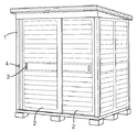
図1ないし図9は本発明に係るラッチ錠を、物置の引戸に適用した実施例を示す。図2において、符号1は戸枠、2は戸枠の開口面に沿って引き違い開閉される戸本体である。戸本体2と戸枠1との閉じ端には、戸本体2を閉じ状態に保持する錠ユニットを設ける。錠ユニットは、戸本体2に組み付けられる錠本体3と、戸枠1に埋設する状態で固定されるラッチ錠用のストライカー4とで構成する。このストライカー4は、鎌錠用のストライカーを兼ねている。
【0016】
図3および図4において、錠本体3は、戸本体2の内面側に組まれる内側ユニット3Aと、戸本体2の外面側に組まれる外側ユニット3Bとからなり、内側ユニット3Aに、仮り錠として用いられる本発明のラッチ錠と、鍵6で鎖錠および解錠操作される鎌錠とが組み込んである。外側ユニット3Bには、ラッチ錠を解錠操作する錠操作機構が設けてある。
【0017】
図4において、内側ユニット3Aは、逆L字形のケース10と、ケース10の内面上部に固定した錠ボディ11を有し、ケース10と錠ボディ11との間に鎌錠とラッチ錠とが組み付けてある。鎌錠7は、錠ボディ11に固定されるシリンダー錠12と、シリンダー錠12の錠軸の端部に固定される操作カム13と、操作カム13で上下操作されるスライド板14と、スライド板14で左右方向へ出退揺動操作される鎌形の錠腕15、および錠腕15を解錠姿勢と鎖錠姿勢の各切換姿勢において位置保持するキックばね16などで構成する。図4に想像線で示すように、錠腕15の先端がストライカー4の内奥裏面壁と係合することにより、戸本体2を開放不能に鎖錠できる。
【0018】
図5において、錠ボディ11は左右に長い逆Ω字状のダイキャスト成形品からなり、その左右中央に先のシリンダー錠12を収容するボス18を有し、ボス18の左右に突出する板面の上隅のそれぞれに、一対のブラケット19が突設してある。このブラケット19で、ラッチ錠のラッチ軸20を回転のみ可能に軸支する。ラッチ軸20はダイキャスト成形品からなり、ラッチ片21と連動片22が一体に成形してある。詳しくは、ラッチ軸20の片方の軸端にラッチ片21を一体に形成し、他方の軸端寄りに逆L字状の連動片22を一体に形成している。連動片22と錠ボディ11との間には、ラッチ軸20を図5に矢印aで示すように時計回転方向(鎖錠方向)へ回動付勢する、捻りコイル形のばね23が装着してある。ラッチ片21は、ブラケット19の突端外面に突出する、側面視が銀杏葉形の爪部24を有し、その湾曲周縁に沿って傾斜面からなるカム部25が形成してある。
【0019】
錠ボディ11はケース10にビスで締結されて、内側ユニット3Aとしてユニット化されており、図6に示すように、内側ユニット3Aを戸本体2の側端内面に装着した状態において、ラッチ片21の大半が取付壁の開口26を介して屋内側へ突出するように取り付ける。この取付状態において、ラッチ軸20の軸中心は、戸本体2の開閉方向に沿って左右水平に配置されている。また、戸本体2を開放した状態において、ラッチ片21のカム部25の上端は、ラッチ軸20の中心を通る水平面の付近に位置している。
【0020】
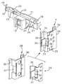
ラッチ片21を介して戸本体2を閉じ位置に保持固定するために、戸枠1にストライカー4を設けている。図5において、ストライカー4は、横断面がコ字形のキャッチ本体28と、キャッチ本体28に組まれる補強板29とからなる。キャッチ本体28の開口縁にはそれぞれフランジ壁30を張り出し、屋内側のフランジ壁30に連続する内側面に、ラッチ片21の進入を許す開口31を通設する。補強板29は、基本断面がL字形のステンレス板材製のプレス金具からなり、キャッチ本体28の底壁外面の側から組まれて、先の開口31の内面周縁を覆う。開口31に臨む補強板29の板面を切り起こして窓部32と舌片33を設け、この舌片33の折り曲げ基端を、ラッチ片21の爪部24を受け止め係合する爪受部34とする。爪受部34に連続して、フランジ壁30の外面へ向かって傾斜する係合案内部35が設けてある。係合案内部35は、戸本体2を閉じ操作するときカム部25と接当して、ラッチ片21をばね23の付勢力に抗して、ラッチ軸20ごと解錠方向へ揺動操作する。先の舌片33は、開口31を介してキャッチ本体28の外面へ突出する。
【0021】
図3において、外側ユニット3Bは、上下に長いカバーケース37と、カバーケース37の前面に組み込まれた錠操作機構とからなる。錠操作機構は、カバーケース37の前面に凹み形成したポケット38の上下壁で軸支される縦軸(揺動軸)39と、一側端が縦軸39に固定された解錠用のレバー40と、縦軸39の上端に一体成形された連動片41と、縦軸39を待機姿勢に回動付勢するばね(図示していない)とからなる。先の内側ユニット3Aと、外側ユニット3Bとを、戸本体2の壁を挟んで内外に配置し、両者をビスで締結することにより、錠本体3が戸本体2と一体化される。この組み付け状態において、錠操作機構の連動片41は、図6に示すようにラッチ軸20に設けた連動片22と内外に隣接している。従って、図7に示すように、レバー40をポケット38の外面側へ向かって揺動操作すると、その動作が縦軸39と連動片41を介してラッチ軸20に設けた連動片22へ伝えられ、その結果、ラッチ軸20が解錠方向へ回動して、ラッチ片21を解錠姿勢に切り換えることができる。
【0022】
上記の錠操作機構は戸本体2の外面に設けてあるので、物置内へ入った状態で戸本体2を閉じてしまうと、錠操作機構を操作することができず、閉じ込められてしまう。このような状況でも、ラッチ錠を戸本体2の内側から解錠操作できるようにするために、補助レバー44を内側ユニット3Aに設けている。詳しくは、図7に示すように、ケース10の側端から突出するラッチ軸20の端部に補助レバー44を固定している。補助レバー44は、待機状態において戸本体2の壁面に沿って起立しているので、ラッチ軸20を中心にして手前側へ傾動操作すると、ラッチ片21を解錠できる。
【0023】
次に、ラッチ片21とストライカー4との係脱動作を説明する。先に説明したように、ラッチ片21は戸本体2の閉じ端の内面側に突出し、爪部24の外側面に設けたカム部25が、ストライカー4の係合案内部35と正対する関係にある。従って、開放されていた戸本体2閉じ操作すると、図8(a)および図9(a)に示すように傾斜面で形成したカム部25の下端側が、傾斜面で形成した係合案内部35と接当する。因みに、係合案内部35の傾斜方向が、戸本体2の開閉平面を基準にして屋内側へ傾斜する2次元平面であるのに対し、カム部25の傾斜面は、爪部24の周縁に沿って湾曲しながら、爪部24の周縁へ向かって傾斜する3次元平面で形成してある。そのため、係合案内部35にカム部25が接当すると、ラッチ片21に解錠方向の回転モーメントが作用し、ラッチ片21およびラッチ軸20は、図8(b)・(c)および図9(b)に示すようにをばね23の付勢力に抗して矢印方向へ揺動操作されて、解錠操作される。このときのカム部25の接当面は、下端側からから上端側へと徐々に変化する。戸本体2を閉じ端の近傍まで閉じ操作し、ラッチ片21の爪部24が爪受部34を通り抜けると、それまで解錠姿勢に保持されていたラッチ片21およびラッチ軸20は、図9(c)に示すようにばね23で鎖錠姿勢へ復帰揺動されるので、爪部24と爪受部34とが係合し戸本体2を閉止状態に保持固定できる。
【0024】
上記のように、爪部24と爪受部34とが係合した状態においては、図1に示すように戸本体2の開放を阻止する閉止力Rの方向と、ラッチ片21の揺動平面が互いに直交する関係にあり、しかも、先の閉止力Rの方向とラッチ軸20の軸中心とが平行な関係にある。そのため、戸本体2に開放方向の外力が作用したとしても、この外力は爪部24と爪受部34とによって受け止められ、ラッチ片21に対して、外力に基づく回転モーメントが作用する余地はない。つまり、爪部24または爪受部34が破壊しない限りは、ラッチ錠が開錠することはあり得ず、地震などの場合にも、戸本体2を確実に閉止保持して、物置内の収納物が出入口から転落し四散するのを防止できる。
【0026】
上記以外に、カム部25の形状や構造は、正対する方向から揺動操作できるものであればよいので、その形状や構造は実施例で説明した形状や構造には限定しない。本発明のラッチ錠は単独で構成することができるので、実施例で説明した錠ユニットのように、鎌錠などの本締り錠を一体に備えている必要はない。上記の実施例では、係合案内部35をキャッチ本体28の屋内側の内側面に設けたがその必要はなく、係合案内部35をキャッチ本体28の内面上壁に設け、爪受部34をキャッチ本体28の内面上壁と直交する内面後壁(または内面前壁)に設けることができる。もちろん、爪受部34はキャッチ本体28の内面上下壁のいずれに設けてあってもよい。ラッチ軸20とラッチ片21は、別の部品として形成でき、その場合のラッチ軸20は金属製あるいはプラスチック製の棒やパイプで形成できる。
【図面の簡単な説明】
【図1】鎖錠状態のラッチ錠の横断平面図である。
【図2】物置の斜視図である。
【図3】ラッチ錠の正面図である。
【図4】錠内部の正面図である。
【図5】ラッチ錠の分解斜視図である。
【図6】解錠状態のラッチ錠の横断平面図である。
【図7】錠操作機構を解錠操作した状態の横断平面図である。
【図8】ラッチ錠の解錠動作を示す概略斜視図である。
【図9】ラッチ錠の解錠動作を示す概略側面図である。
【符号の説明】
1 戸枠
2 戸本体
3 錠本体
4 ストライカー
11 錠ボディ
20 ラッチ軸
21 ラッチ片
22 連動片
23 ばね
24 爪部
25 カム部
34 爪受部
35 係合案内部[0001]
BACKGROUND OF THE INVENTION
The present invention relates to a latch lock provided on a door main body that opens and closes an entrance and exit, and in particular, to a latch lock in which a latch piece swings and disengages from a striker.
[0002]
[Prior art]
This type of swing type latch lock is known, for example, from Japanese Utility Model Publication No. 5-7408. In this case, the latch piece can be engaged with or released from the striker by swinging horizontally in and out of the door body. Incidentally, this type of latch lock is often applied to sliding doors.
[0003]
[Problems to be solved by the invention]
As described above, the latch piece of the latch lock configured to swing back and forth is moved and urged by the spring so as to always protrude from the outer surface of the door body. Therefore, in a state where the door main body is opened, it is unavoidable that the latch piece protrudes greatly from the door main body, and when passing through the doorway, part of the clothes may be caught on the claw portion at the protruding end of the latch piece. In some cases, the latch piece may be deformed and cannot be properly engaged with the striker.
[0004]
Further, this type of latch piece has a structure in which the closing holding force in a state where the latch piece and the striker are engaged follows the swinging plane of the latch piece, and further, the latch piece and the striker engage. The locked state is maintained by the biasing force of the spring. Therefore, when a strong external force in the opening direction is applied to the door body due to, for example, an earthquake, a moment in the unlocking direction is applied to the latch piece, and the claw portion is detached from the striker and the door body is opened. In particular, when the swing center of the latch piece and the engaging portion of the claw portion and the striker are shifted back and forth, even if the external force acting on the door body is not as great as the left, it is easily unlocked. There are drawbacks.
[0005]
The object of the present invention is to eliminate the large protrusion of the latch piece from the door body. Therefore, when passing through the doorway, a part of the clothes is caught on the claw portion of the protruding end of the latch piece, or the latch piece is deformed. An object of the present invention is to provide a latch lock that can solve the problem. Another object of the present invention is to reliably prevent the latch lock from being unlocked even when a strong external force is applied to the door body, and to close the door body even in the event of a disaster such as an earthquake. It is to provide a latch lock that can be held on the door.
[0006]
[Means for Solving the Problems]
The latch lock of the present invention includes a
[0007]
The latch lock described above can be applied to both sliding doors and hinged doors. However, when applied to a sliding door, the
[0008]
The lock operating mechanism is supported by a
[0009]
The
[0010]
[Effects of the invention]
In the latch lock of the present invention, the
[0011]
In the locked state in which the
[0012]
When the latch lock is applied to the sliding door, the axis of the
[0013]
A lock operating mechanism comprising a
[0014]
When the
[0015]
【Example】
FIG. 1 thru | or FIG. 9 shows the Example which applied the latch lock based on this invention to the sliding door of a storeroom. In FIG. 2,
[0016]
3 and 4, the
[0017]
In FIG. 4, the
[0018]
In FIG. 5, the
[0019]
The
[0020]
In order to hold and fix the
[0021]
In FIG. 3, the
[0022]
Since the above-described lock operation mechanism is provided on the outer surface of the door
[0023]
Next, the engagement / disengagement operation of the
[0024]
As described above, in the state where the
[0026]
In addition to the above, the shape and structure of the
[Brief description of the drawings]
FIG. 1 is a cross-sectional plan view of a latch lock in a locked state.
FIG. 2 is a perspective view of a storage room.
FIG. 3 is a front view of the latch lock.
FIG. 4 is a front view of the inside of the lock.
FIG. 5 is an exploded perspective view of a latch lock.
FIG. 6 is a cross-sectional plan view of the latch lock in the unlocked state.
FIG. 7 is a cross-sectional plan view showing a state where the lock operation mechanism is unlocked.
FIG. 8 is a schematic perspective view showing an unlocking operation of the latch lock.
FIG. 9 is a schematic side view showing the unlocking operation of the latch lock.
[Explanation of symbols]
DESCRIPTION OF
Claims (3)
錠本体(3)は、錠ボディ(11)と、錠ボディ(11)に回転のみ可能に軸支され、軸中心が戸本体(2)の開閉方向に沿ってほぼ水平に配置されるラッチ軸(20)と、ラッチ軸(20)の軸端にラッチ軸(20)と同行回転するよう設けられ、戸本体(2)の閉じ端に備えられていて、戸本体(2)の厚み方向において戸本体(2)の屋内面側に突出するラッチ片(21)と、ラッチ軸(20)をラッチ片(21)がストライカー(4)と係合する向きに回動付勢するばね(23)とを含み、
ストライカー(4)には、爪受部(34)と、爪受部(34)に連続して傾斜面で形成した係合案内部(35)とが設けられており、
ラッチ片(21)は、ストライカー(4)の爪受部(34)に受け止められる爪部(24)と、爪部(24)の外側面に傾斜面で形成したカム部(25)とを備えていて、爪部(24)が爪受部(34)に係合して戸本体(2)を閉止保持する鎖錠姿勢と、爪部(24)が爪受部(34)から離脱する解錠姿勢とに、ラッチ軸(20)を中心にして揺動変位でき、
前記ラッチ片(21)のカム部(25)は、ストライカー(4)の係合案内部(35)と正対する関係にあり、
戸本体(2)を閉じ操作したとき、ラッチ片(21)のカム部(25)がストライカー(4)の係合案内部(35)に接当して、ラッチ片(21)をばね(23)の付勢力に抗してラッチ軸(20)ごと解錠方向へ揺動操作し、
爪部(24)と爪受部(34)とが係合した状態における戸本体(2)の開放を阻止する閉止力(R)の方向と、ラッチ片(21)の揺動平面とが、互いに交差する向きに設定され、かつ、前記閉止力(R)の方向とラッチ軸(20)の軸中心とがほぼ平行に設定されており、
ラッチ軸(20)には、戸本体(2)の内側からラッチ片(21)を解錠姿勢に操作するための補助レバー(44)が固定されていることを特徴とするラッチ錠。A lock body (3) assembled to the door body (2) of the sliding door, a striker (4) fixed in an embedded state in the door frame (1), and an outer surface of the door body (2), 3) a latch lock comprising a lock operating mechanism for unlocking operation,
The lock body (3) is pivotally supported by the lock body (11) and the lock body (11) so as to be rotatable only, and the shaft center is arranged substantially horizontally along the opening / closing direction of the door body (2). (20), provided at the shaft end of the latch shaft (20) so as to rotate together with the latch shaft (20), provided at the closed end of the door body (2), and in the thickness direction of the door body (2) A latch piece (21) protruding to the indoor surface side of the door body (2), and a spring (23) for biasing the latch shaft (20) in a direction in which the latch piece (21) engages the striker (4). Including
The striker (4) is provided with a claw receiving part (34) and an engagement guide part (35) formed by an inclined surface continuously to the claw receiving part (34),
The latch piece (21) includes a claw portion (24) received by the claw receiving portion (34) of the striker (4), and a cam portion (25) formed by an inclined surface on the outer surface of the claw portion (24). The locking position in which the claw portion (24) engages with the claw receiving portion (34) and holds the door body (2) closed, and the claw portion (24) is detached from the claw receiving portion (34). It can be rocked and displaced around the latch shaft (20) in the locked position,
Cam portions of the latch piece (21) (25) are in directly opposite relationship engaging guide portion (35) of the striker (4),
When the door body (2) is closed, the cam portion (25) of the latch piece (21) comes into contact with the engagement guide portion (35) of the striker (4), and the latch piece (21) is moved to the spring (23 ) Swing the latch shaft (20) in the unlocking direction against the urging force of
The direction of the closing force (R) that prevents the door body (2) from opening in the state where the claw portion (24) and the claw receiving portion (34) are engaged, and the swing plane of the latch piece (21), The direction of the closing force (R) and the axial center of the latch shaft (20) are set substantially parallel to each other.
A latch lock characterized in that an auxiliary lever (44) for operating the latch piece (21) to an unlocked posture from the inside of the door body (2) is fixed to the latch shaft (20).
Priority Applications (1)
| Application Number | Priority Date | Filing Date | Title |
|---|---|---|---|
| JP2001017087A JP3749667B2 (en) | 2001-01-25 | 2001-01-25 | Latch lock |
Applications Claiming Priority (1)
| Application Number | Priority Date | Filing Date | Title |
|---|---|---|---|
| JP2001017087A JP3749667B2 (en) | 2001-01-25 | 2001-01-25 | Latch lock |
Publications (2)
| Publication Number | Publication Date |
|---|---|
| JP2002220956A JP2002220956A (en) | 2002-08-09 |
| JP3749667B2 true JP3749667B2 (en) | 2006-03-01 |
Family
ID=18883343
Family Applications (1)
| Application Number | Title | Priority Date | Filing Date |
|---|---|---|---|
| JP2001017087A Expired - Fee Related JP3749667B2 (en) | 2001-01-25 | 2001-01-25 | Latch lock |
Country Status (1)
| Country | Link |
|---|---|
| JP (1) | JP3749667B2 (en) |
Families Citing this family (1)
| Publication number | Priority date | Publication date | Assignee | Title |
|---|---|---|---|---|
| JP4664817B2 (en) * | 2003-10-10 | 2011-04-06 | シロキ工業株式会社 | Striker |
-
2001
- 2001-01-25 JP JP2001017087A patent/JP3749667B2/en not_active Expired - Fee Related
Also Published As
| Publication number | Publication date |
|---|---|
| JP2002220956A (en) | 2002-08-09 |
Similar Documents
| Publication | Publication Date | Title |
|---|---|---|
| JP4559968B2 (en) | Self-latching device | |
| US7591494B2 (en) | Window lock assembly | |
| JP3749667B2 (en) | Latch lock | |
| JP4623620B2 (en) | Sickle tablets | |
| KR100648574B1 (en) | double locking crossbar | |
| JP3316721B2 (en) | Cabinet locking device | |
| JP3650195B2 (en) | sash | |
| JPS6012849Y2 (en) | Door latch device for furniture, etc. | |
| JP4369081B2 (en) | Locking device for gaming machine | |
| JP3491784B2 (en) | Temporary sickle tablet | |
| JP4216972B2 (en) | Ventilation lock device for sliding shoji | |
| JP5016257B2 (en) | Locking device for gaming machines | |
| JP4879721B2 (en) | Door locking device | |
| JP3650196B2 (en) | sash | |
| JP3929461B2 (en) | Crescent tablets | |
| JP3503003B2 (en) | Locking device for doors in cabinets | |
| JPS6134471Y2 (en) | ||
| JP4514076B2 (en) | Sickle tablets | |
| JP4320289B2 (en) | Crescent tablets | |
| JPH05295939A (en) | Door lock mechanism for furnitures such as locker | |
| JP2008023203A (en) | Locking mechanism for game machine or the like | |
| JPH08151841A (en) | Locking device for double hinged door | |
| JP5130256B2 (en) | Lock-out prevention device for thumb turn lock on indoor door | |
| JP4195310B2 (en) | Game machine locking device | |
| JPH0421987Y2 (en) |
Legal Events
| Date | Code | Title | Description |
|---|---|---|---|
| A977 | Report on retrieval |
Free format text: JAPANESE INTERMEDIATE CODE: A971007 Effective date: 20041208 |
|
| A131 | Notification of reasons for refusal |
Free format text: JAPANESE INTERMEDIATE CODE: A131 Effective date: 20050202 |
|
| A521 | Written amendment |
Free format text: JAPANESE INTERMEDIATE CODE: A523 Effective date: 20050401 |
|
| A131 | Notification of reasons for refusal |
Free format text: JAPANESE INTERMEDIATE CODE: A131 Effective date: 20050803 |
|
| A521 | Written amendment |
Free format text: JAPANESE INTERMEDIATE CODE: A523 Effective date: 20050902 |
|
| TRDD | Decision of grant or rejection written | ||
| A01 | Written decision to grant a patent or to grant a registration (utility model) |
Free format text: JAPANESE INTERMEDIATE CODE: A01 Effective date: 20051109 |
|
| A61 | First payment of annual fees (during grant procedure) |
Free format text: JAPANESE INTERMEDIATE CODE: A61 Effective date: 20051202 |
|
| R150 | Certificate of patent or registration of utility model |
Free format text: JAPANESE INTERMEDIATE CODE: R150 Ref document number: 3749667 Country of ref document: JP Free format text: JAPANESE INTERMEDIATE CODE: R150 |
|
| FPAY | Renewal fee payment (event date is renewal date of database) |
Free format text: PAYMENT UNTIL: 20081209 Year of fee payment: 3 |
|
| FPAY | Renewal fee payment (event date is renewal date of database) |
Free format text: PAYMENT UNTIL: 20091209 Year of fee payment: 4 |
|
| R250 | Receipt of annual fees |
Free format text: JAPANESE INTERMEDIATE CODE: R250 |
|
| FPAY | Renewal fee payment (event date is renewal date of database) |
Free format text: PAYMENT UNTIL: 20091209 Year of fee payment: 4 |
|
| FPAY | Renewal fee payment (event date is renewal date of database) |
Free format text: PAYMENT UNTIL: 20101209 Year of fee payment: 5 |
|
| R250 | Receipt of annual fees |
Free format text: JAPANESE INTERMEDIATE CODE: R250 |
|
| FPAY | Renewal fee payment (event date is renewal date of database) |
Free format text: PAYMENT UNTIL: 20111209 Year of fee payment: 6 |
|
| R250 | Receipt of annual fees |
Free format text: JAPANESE INTERMEDIATE CODE: R250 |
|
| FPAY | Renewal fee payment (event date is renewal date of database) |
Free format text: PAYMENT UNTIL: 20111209 Year of fee payment: 6 |
|
| FPAY | Renewal fee payment (event date is renewal date of database) |
Free format text: PAYMENT UNTIL: 20121209 Year of fee payment: 7 |
|
| R250 | Receipt of annual fees |
Free format text: JAPANESE INTERMEDIATE CODE: R250 |
|
| FPAY | Renewal fee payment (event date is renewal date of database) |
Free format text: PAYMENT UNTIL: 20131209 Year of fee payment: 8 |
|
| R250 | Receipt of annual fees |
Free format text: JAPANESE INTERMEDIATE CODE: R250 |
|
| R250 | Receipt of annual fees |
Free format text: JAPANESE INTERMEDIATE CODE: R250 |
|
| R250 | Receipt of annual fees |
Free format text: JAPANESE INTERMEDIATE CODE: R250 |
|
| R250 | Receipt of annual fees |
Free format text: JAPANESE INTERMEDIATE CODE: R250 |
|
| R250 | Receipt of annual fees |
Free format text: JAPANESE INTERMEDIATE CODE: R250 |
|
| R250 | Receipt of annual fees |
Free format text: JAPANESE INTERMEDIATE CODE: R250 |
|
| R250 | Receipt of annual fees |
Free format text: JAPANESE INTERMEDIATE CODE: R250 |
|
| R250 | Receipt of annual fees |
Free format text: JAPANESE INTERMEDIATE CODE: R250 |
|
| LAPS | Cancellation because of no payment of annual fees |