JP3749552B2 - Method and apparatus for printing an image on a substrate and method for printing a color image on a substrate - Google Patents
Method and apparatus for printing an image on a substrate and method for printing a color image on a substrate Download PDFInfo
- Publication number
- JP3749552B2 JP3749552B2 JP05400695A JP5400695A JP3749552B2 JP 3749552 B2 JP3749552 B2 JP 3749552B2 JP 05400695 A JP05400695 A JP 05400695A JP 5400695 A JP5400695 A JP 5400695A JP 3749552 B2 JP3749552 B2 JP 3749552B2
- Authority
- JP
- Japan
- Prior art keywords
- image
- pixels
- correction
- printing
- substrate
- Prior art date
- Legal status (The legal status is an assumption and is not a legal conclusion. Google has not performed a legal analysis and makes no representation as to the accuracy of the status listed.)
- Expired - Fee Related
Links
Images


Classifications
-
- H—ELECTRICITY
- H04—ELECTRIC COMMUNICATION TECHNIQUE
- H04N—PICTORIAL COMMUNICATION, e.g. TELEVISION
- H04N1/00—Scanning, transmission or reproduction of documents or the like, e.g. facsimile transmission; Details thereof
- H04N1/40—Picture signal circuits
- H04N1/407—Control or modification of tonal gradation or of extreme levels, e.g. background level
- H04N1/4072—Control or modification of tonal gradation or of extreme levels, e.g. background level dependent on the contents of the original
-
- H—ELECTRICITY
- H04—ELECTRIC COMMUNICATION TECHNIQUE
- H04N—PICTORIAL COMMUNICATION, e.g. TELEVISION
- H04N1/00—Scanning, transmission or reproduction of documents or the like, e.g. facsimile transmission; Details thereof
- H04N1/40—Picture signal circuits
- H04N1/40025—Circuits exciting or modulating particular heads for reproducing continuous tone value scales
- H04N1/40031—Circuits exciting or modulating particular heads for reproducing continuous tone value scales for a plurality of reproducing elements simultaneously
-
- H—ELECTRICITY
- H04—ELECTRIC COMMUNICATION TECHNIQUE
- H04N—PICTORIAL COMMUNICATION, e.g. TELEVISION
- H04N1/00—Scanning, transmission or reproduction of documents or the like, e.g. facsimile transmission; Details thereof
- H04N1/46—Colour picture communication systems
- H04N1/56—Processing of colour picture signals
- H04N1/60—Colour correction or control
- H04N1/603—Colour correction or control controlled by characteristics of the picture signal generator or the picture reproducer
- H04N1/6033—Colour correction or control controlled by characteristics of the picture signal generator or the picture reproducer using test pattern analysis
Landscapes
- Engineering & Computer Science (AREA)
- Multimedia (AREA)
- Signal Processing (AREA)
- Image Processing (AREA)
- Facsimile Image Signal Circuits (AREA)
- Color Image Communication Systems (AREA)
- Color, Gradation (AREA)
- Ink Jet (AREA)
Description
【0001】
【産業上の利用分野】
本発明は一般に基板上でのイメージの印刷に関する。より詳しくは、本発明は連続するパスで反復的に基板上でイメージを走査・印刷する手法に関する。
【0002】
【従来の技術】
印刷装置から最も正確なイメージを生成するために用いられる技術はかなり多数ある。一般に、印刷装置が所望のイメージにできるだけ近づきうるように、誤差拡散及びディザー法のような複雑なアルゴリズムが用いられる。これらの従来の技術にもかかわらず、なお今日まで、大抵の印刷装置は、基本的には、実際に生成されるイメージを知ることができない。印刷装置は、基板に付着されるインクの適切な量の "最良の推定" の域を越えない。 "最良の推定" は印刷装置を開発した技術者の観察によって行われているが、通常、それは印刷装置開発中に用いられた比較的限られた数のイメージの間の妥協を表わす。これらの妥協のなかには受け入れできないものがありうるとの認識の下に、印刷技術のなかには、訓練された操作員が実際の印刷装置の出力に基づいてパラメータを調整できるものがある。
【0003】
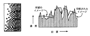
図1は従来の技術で経験された問題を示す。大抵の市販の印刷装置は、限られた範囲で画素の明暗度を変更できる。誤差拡散は、モネの画法のように、濃い画素の比率を変えることにより、完全なグレースケールの出現を可能にする。用紙上の当該特定の位置の上をその印刷装置のヘッドが移動するとき、所望のイメージに基づいて、インクジェット印刷装置のヘッドからの特定のインクジェット又はインパクト印刷装置からのワイヤが射出されるべきかどうかを決定する計算が行われる。実際のイメージの所望の濃度が、当該位置にインクが射出された場合の用紙上のインクの推定濃度と比較される。インクジェットノズルが射出されると、図1の縦方向の縞で示すように、実現された濃度は予め計算された濃度から幅広く変化する。実現された濃度のこの変化により、印刷されたイメージはノイズのあるイメージになる。
【0004】
従来の技術により印刷装置に提供される光学フィードバックは限定されている。例えば、実際の印刷動作中に修正を加えるために、LED 又はレーザー印刷装置により生成された光を測定することが知られている。感知された光の量に応答して、LED 又はレーザーへの駆動電流を増減するか又は露出時間を変えることにより調整が行われる。しかしながら、このフィードバックは用紙上に実際に何が生成されているかを測定するものではないが、射出された光の量をより正確に制御する手段を提供する。類似のフィードバック手法が複写機の技術に存在する。光学フィードバックと印刷とを組合せるもう1つの例は従来の記録するための技術にもある。例えば、スクリーン印刷装置で、連続するカラーのプレートをイメージの生成に用いる場合、印刷されたイメージを、後続するイメージの印刷のために記録する目的で位置決めすることが知られている。しかしながら、連続する印刷ステージ中に実際に印刷されるイメージと所望のイメージとの間の変化を修正する準備がない。
【0005】
本発明は光学フィードバックに基づいて印刷装置出力を補正する手段を提供する。
【0006】
【発明が解決しようとする課題】
本発明の第1の目的は印刷されたイメージの品質を改善することにある。
本発明の第2の目的は光学的なフィードバックを印刷装置に提供することにある。
本発明の第3の目的はイメージが印刷される基板における非均一性に関して補償することにある。
【0007】
【課題を解決するための手段】
これら及びその他の目的は、印刷パスの前に基板上に既にあるイメージを調べるセンサーを有し、複数のパスで基板上にイメージを印刷する印刷装置により達成される。現在の印刷パスで所望のイメージを得るために、各印刷パスの前に走査されたイメージを用いることにより基板上に乗せるインクの量が決定される。基板上のイメージをセンサーが走査する。最初の印刷パスでは、走査されたイメージは未使用の基板である。走査されたイメージの画素のセット(組)は、所望のイメージにおける対応する画素のセットよりも低い明暗度を有する。対応する走査されたイメージ画素と所望のイメージ画素の間の相違を用いて補正画素のセットを計算し、この相違が部分的に補正される。補正画素は印刷ヘッドにより基板に印刷される。次のパスで、センサーを用いて前のパスの結果が評価され、そして次の補正画素のセットが計算され印刷される。最後の印刷パスでは、対応する走査されたイメージ画素と所望のイメージ画素のイメージの明暗度の間の全体の相違、及び前のパスでの部分的な相違によって各補正画素が印刷される。
【0008】
補正画素のセットの各々が隣接する画素からの誤差拡散を用いて計算されるように補正画素の計算を改良することができる。更に、基板における非均一性を補償することができる。センサーの観察により最初の印刷パスの間に基板のカラー及び色相の非均一性が自動的に補償される。最初の印刷パスで基板上の特定の位置での動作が基板上の他の位置での動作と異なる、例えば、用紙繊維の非均一性又は光沢の変化のために容易にインクが付着しないことが観察されることもある。次の印刷パスで当該位置の補正画素を調整して前記動作の相違を補償することができる。
【0009】
1つの良好な実施例では、線形配列(アレイ)状に複数の補正画素を印刷するように印刷ヘッドが構成される。補正画素を印刷する直前に基板上のイメージが走査されるように印刷ヘッドの概ね前方にセンサーが置かれる。印刷ヘッド及びセンサーの両者は、印刷パスの間に、基板と平行で且つ線形配列に直交する方向に移動される。或る印刷パスから次の印刷パスに移るとき、印刷ヘッド及びセンサーの両者は、線形配列に平行する方向に移動されるが、移動される量は線形配列の長さよりも短い。従って、所与の時点で印刷ヘッドにある異なる素子により印刷された補正画素は異なる印刷パスに属する。
【0010】
【実施例】
本発明は印刷装置によって可能な最も正確なイメージを提供するために光学フィードバックに依存する。理論的には、無限のパス数を用いることができる。添付された図面に示された実施例では、三つのパスが描かれている。2、又は3以上の印刷パスを用いうることを当業者は認識するであろう。
【0011】
図2に示すように、第1のパスは何も書かれていない基板、例えば、用紙上で行われる。第1のパスは最初の不鮮明なイメージを印刷する。印刷装置はインクを追加することしかできないので、最初の不鮮明なイメージは所望のイメージよりも薄くなければならず、従って印刷装置が最初のパスで印刷しようとするイメージ、即ち、目標イメージは最終的に所望されるイメージよりも濃度が小さい。目標イメージと所望のイメージの間の最適比率は、印刷装置誤差、及び後続するパスの数の関数であり、特定の印刷装置について経験的に見出だすことができる。印刷装置の誤差が大きければ大きいほど、そして印刷するパスの数が多ければ多いほど、目標イメージと所望のイメージの間の相違が大きくなるであろう。3つのパスの代表的なインクジェット印刷装置では、第1の目標イメージと所望のイメージの間の70%の比率は受け入れ可能な結果を与える。比率が高すぎる場合、ノイズ、補正できない誤差により第1のパスで最終的な所望の濃度を越える画素を印刷する危険がある。比率が低すぎる場合には、最終的な所望の濃度への収斂が遅くなり、より多くのパスを必要とするか、又は最後のパスで、後続するフィードバックなしに補正すべき、より大きい誤差が残される。
【0012】
基板における変動、例えば組織及び毛管作用により常に一定のインク量が同じ濃度を生ずるとは限らない。任意選択として、アルゴリズムは、初期のパスで特定の画素の下の基板部分が予想された濃度で印刷しなかったことを基板の不規則性によるものとして記憶できる。後続のパスは、この情報を用いて所望の濃度と実際の濃度の間の相違を埋めるように印刷するだけではなく、当該画素の下の用紙への前にインクの付加が不足した分だけ、この相違を増すことができる。
【0013】
所望のインク濃度に基づいて、印刷ヘッドが用紙上を移動するとき、印刷ヘッドの各特定のインクノズルを射出すべきか否かの判定が行われる。目標イメージの所望のインク濃度が用紙の濃度と比較される。現在の濃度が用紙から測定され、そしてその濃度に予想されるインクの流れを加算することによって、インクノズルがその用紙位置に射出された場合の推定濃度が計算される。比較は直線的な照明空間で行われ、そしてノズルを射出する決定はどの用紙濃度が所望の濃度に最も近いかどうかに基づいて行われる。所望のイメージと不鮮明なパス1の結果の間の相違が誤差イメージである。誤差イメージ自身は、それが第1のパスから打消される全ての誤差及び相対的に僅かな残留イメージを含むとき非常に不鮮明であるように見えるであろう。印刷されたこの誤差イメージは第2のパスで印刷するのに用いられる。しかしながら、第1のパスの目標誤差イメージは実際の誤差イメージよりも小さい。第2のパスの後のイメージは第1及び第2のパスの累積結果であり、後のパスで満たすことができる。
【0014】
所望のイメージとパス2の後のイメージの間の相違が第2の誤差となる。これはなおノイズを有するが、パス2で付加されたインクの濃度はパス1で付加された濃度よりも薄かったので、このノイズはずっと小さい。最後のパスで、印刷装置は明暗度を減少させずに完全な誤差イメージを印刷しようとする。しかしながら、最後のパスで付加されるインクの量が非常に少なくなるにつれて、補正されない誤差も非常に小さくなるであろう。最初の2つのパスが目標濃度を濃度の相違の70%で印刷した場合、用紙上の累積イメージは所望の濃度の91%となり、第2のパスの後に残るのは、最後のパスで補正される9%である。従って、イメージの最後のノイズは、光学フィードバックなしで動作する従来の技術の印刷装置のノイズの9%に過ぎない。
【0015】
連続する印刷パス及び光学フィードバックの使用により、従来の技術で可能であったよりも正確なイメージを生成することができる。
【0016】
従来の技術のように、グレー段階の数が限られている印刷装置のグレースケールを円滑にするために各パスで誤差拡散を用いることができる。画素毎に、実現できる最も近いグレー段階が印刷される。例えば、印刷装置は一定量のインクを付着させることができるか又は全くインクを付着させることができない。目標濃度と印刷後の実際の用紙濃度の間には、ある予想された誤差がある。この誤差は、隣接する、まだ印刷されていない補正画素から差引かれ、小さな領域にわたって打消される。印刷ヘッドが基板を横切って左から右に且つ上部から下部に移動するとき、現在の位置のすぐ右の画素から誤差の半分が差引かれ、そして現在の位置のすぐ下の画素からも誤差の半分が差引かれる。特定のイメージの下部の列では、現在の位置の右の画素から全ての誤差を差引くことができる。
【0017】
本発明の原理は通常の汎用コンピュータに接続された印刷装置で実現することができる。図3は、システムユニット11、キーボード12、マウス13、表示装置14及び印刷装置15を備えるコンピュータ10を示す。
【0018】
使用される印刷装置技術は複数のパスでインクが累積できなければならない。この場合、将来技術改善が行われない限り色素昇華及びレーザーのような技術は除外される。インパクトリボン印刷装置は、複数のパスでインクの一部が逆に用紙からリボンに転写されるので理想的ではない。リボンへのインクの逆転写は完全なグレースケールを困難なものにし、そしてカラーリボン上のカラーを濁ったものにする。インクジェット技術は本発明によく適している。更に、本発明の光学フィードバックにより克服されるインクジェット印刷の問題のなかには、用紙繊維の毛管作用で生じる微小な斑点もある。インクは、明るいグレイの制御ができるように、代表的なインクジェット印刷装置で用いられるよりも光学的に薄い(淡い)濃度にすべきである。明暗度の少ないインクは、より少ない染料又は色素を担体に加えることにより容易に作ることができる。複数のパスを用いて濃いブラックを累積的に作ることができる。
【0019】
図4は図3に示されたパーソナルコンピュータの構成要素のブロック図を示す。システムユニット11は、種々の構成要素を結合して種々の構成要素の間の通信を行う1つ又は複数のシステムバス21を備える。マイクロプロセッサ22はシステムバス21に接続され、そして同じくシステムバス21に接続されている読取り専用メモリ(ROM) 23及びランダムアクセスメモリ(RAM) 24によりサポートされる。IBM マルチメディアPS/2シリーズのコンピュータ内のマイクロプロセッサは、インテルファミリの、386 又は486 マイクロプロセッサを含む、マイクロプロセッサの1つである。しかしながら、PowerPC モデル601 又は 604、モトローラファミリのマイクロプロセッサ、例えば 68000、68020 又は 68030マイクロプロセッサ及び、 IBM、ヒューレットパッカード、サン、インテル、モトローラその他により製造された種々の縮小命令セットコンピュータ(RISC)マイクロプロセッサを含む、しかしそれらに限定されない、他のマイクロプロセッサを用いることもできる。
【0020】
ROM 23はとりわけ基本入出力システム(BIOS)を含む。これは対話のような基本ハードウェア動作、ディスク装置及びキーボードを制御する。RAM 24はメインメモリであり、このメモリにオペレーティングシステム及びアプリケーションプログラムがロードされる。メモリ管理チップ 25はシステムバス21に接続されて直接メモリアクセス動作を制御する。この動作はRAM 24、ハードディスク装置26及びフロッピーディスク装置27の間のデータの引渡しを含む。CD ROM 32 もシステムバス21に接続され、大量のデータ、例えばマルチメディアプログラム又は大型データベースを記憶するために用いられる。
【0021】
システムバス21には、種々のI/O 制御装置: キーボード制御装置28、マウス制御装置29、ビデオ制御装置30、プリンタ制御装置31及びセンサー制御装置33も接続される。キーボード制御装置28はキーボード12のハードウェアインタフェースを、マウス制御装置29はマウス13のハードウェアインタフェースを提供し、ビデオ制御装置30は表示装置14のハードウェアインタフェースであり、そしてプリンタ制御装置31は印刷ヘッド17及び印刷装置15のハードウェアインタフェースである。センサー制御装置33はセンサー16のハードウェアインタフェースである。
【0022】
図3及び図4には、印刷装置15及びセンサー16をそれぞれ制御する制御装置31及び33のカードが別々に示される。これらの機能は一枚のカードで、又はたぶんコンピュータのマザーボードで提供しうることも当業者は認識するであろう。
本発明の良好な実施例の1つはランダムアクセスメモリ24に存在するコードモジュールにある命令のセットである。コンピュータシステムが要求するまで、命令のセットは別のコンピュータメモリ、例えば、ハードディスク装置26に、最終的にはCD ROM 32 での使用のために光学ディスクに、又は最終的にはフロッピーディスク装置27での使用のためにフロッピーディスクに記憶しておくことがある。プリンタドライバ54及びセンサードライバ56は、残りのソフトウェアが印刷装置の特定のハードウェア要求を知ることから切離すソフトウェアである。1つの良好な実施例では、これらのドライバは、印刷装置15が本発明の原理によって動作することを可能にするソフトウェアを含む。あるいは、これらの機能は、プリンタ制御装置31及びセンサー制御装置33にあるファームウェア又はハードウェアで、又は印刷装置自身にあるハードウェアで実現することができる。アプリケーション58及び59は、プリンタドライバ54に引渡され、そして最終的には印刷装置15で印刷されるるイメージを、オペレーティングシステムに提供する。
【0023】
オペレーティングシステムからイメージを受取った後、プリンタドライバ54は、印刷装置15がインクを付着させることができる画素解像度で複数の画素のイメージを定義する。このように、印刷装置が印刷できる点毎に、関連イメージ濃度を有する関連イメージ画素が存在するように印刷装置の解像度で入力イメージが受取られるか又は変換される。
【0024】
1つの実施例では、印刷ヘッドの下を通過する直前に用紙又は他の基板が調べられるように、印刷ヘッドの前縁右側にカメラが取付けられる。このカメラはCCD アレイのような垂直センサーアレイでもよい。このアレイ中のセンサーは、印刷ヘッドのインクジェットが付着される位置に対応する行に等しい数を有するとともにそれらの行に正確に焦点あわせされる。あるいは、前記カメラは、イメージを印刷ヘッドのインクジェット位置レベルに分解するために、プリンタ制御装置又はセンサー制御装置のデバイスドライバに依存する、より多くのセンサーを備えていてもよい。この後者のアプローチが望ましいのは、それによって高精度の機械的な位置合わせが不要になるからである。センサー制御装置33にあるプロセッサか、あるいはコンピュータ10のマイクロプロセッサ22は、センサーが感知したイメージを解釈するソフトウェアと一緒に用いられる。走査された用紙の列の上を印刷ヘッドが移動するまでイメージ解釈の計算結果を保持するようにキュー又は他の記憶手段が用いられる。
【0025】
図5は、基板100 を横切って移動する印刷ヘッドアセンブリ99の詳細を示す。印刷ヘッドアセンブリ99はベアリング101 上のスライダ102 により左から右に滑動する。図5の平面図に示すように、センサー105 及びレンズ106 は左から右への移動に関し、インクジェット印刷ヘッド107 よりも前に位置している。レンズ106 を通して基板100 の特定の領域を線形配列のセンサー105 が走査する。印刷ヘッド107 が走査領域を通過するとき、インクジェットが射出される。走査プロセスの間、ランプ109 が基板100 を照明する。
【0026】
図6に示された1つの良好な実施例では、印刷装置の印刷ヘッドは垂直配列の9つのインクジェットが備えられている。印刷ヘッドは基板上を左から右へ水平に移動する。印刷ヘッドの各水平移動の後、用紙が3印刷画素だけ垂直に送られる。従って、下部の3つの印刷ヘッドのインクジェットは常に未印刷の用紙上を通過し、中央の3つのインクジェットは、下部の3つのインクジェットにより印刷された用紙上を第2のパスで通過し、そして上部の3つのインクジェットは第3の最後のパスで用紙上を通過する。代替の実施例では、3つの印刷画素の替わりに、2及び2/3画素(8/3画素)よりも僅かに少ない量だけ用紙を送ることができる。このように基板を進めることにより、画素は他のパスからの画素の間隙に置かれるので、テレビジョンの表示走査線がインタレースで取り除かれるのと同じように、印刷装置走査線のアーティファクトが除去される。
【0027】
図6は、一連のパス151、153、155、157及び159 で用紙100 のような基板の上を通るセンサー105 及び印刷ヘッド107 を示す。図面で個々のパスが分かるように、便宜的にそれらの水平位置は僅かに変位されている。実際には、これらの変位はない。印刷ヘッドは3つの領域161、162及び163 を印刷する現在のパス159 上に示される。第1の領域161 内のインクジェットは未印刷の用紙上の最初のパスを印刷する。第2の領域162 内のインクジェットは前のパス157 で印刷された領域を含め2番目のパスを印刷する。第3の領域163 内のインクジェットは前の2つのパス157、155で印刷された領域を含め最後のパスを印刷する。
【0028】
図7は印刷プロセスの流れ図を示す。プロセスはステップ200 で始まり、ステップ201 で印刷ヘッドを基板に位置合わせする、即ち用紙を開始位置に進める。ステップ203 で、印刷ヘッドが用紙を横切って移動を開始する。ステップ205 で、印刷ヘッドと整合している基板のセンサー視野から基板のイメージが受取られる。ステップ207 で、必要なら、当該イメージが印刷装置の画素の解像度のサイズに変更される。ステップ209 で、当該イメージが実際の用紙濃度に変換される。濃度の単位は、例えば、未印刷の用紙上の当該濃度に達するのに必要な計算されたインク量とすることができる。ステップ211 で、所望のイメージがコンピュータから検索される。例えば、コンピュータメモリに記憶されている出版アプリケーションで所望のイメージを生成することができる。補正濃度、即ち用紙濃度に付加されたとき所望の濃度が生じると予想されるインクの量を得るために当該特定の画素の所望のイメージ濃度から用紙濃度が差引かれる。ステップ213 で、上部の3つの画素、即ち最後のパスについて、正しい濃度の印刷に最も近づくと予想される印刷コマンドが計算される。ステップ215 で、行き過ぎることなく、補正濃度の印刷に最も近づくと予想される、即ち完全な補正濃度よりも幾らか薄い濃度を与える印刷コマンドで下部の6つの画素が計算される。この "幾らか薄い濃度" が上述の目標濃度であり、例えば完全補正の70%である。ステップ217 で、走査された画素に印刷ヘッドが達したとき印刷装置を活動化させインクジェットを射出させるために印刷コマンドがキューに入れられる。ステップ219 で、印刷ヘッドアセンブリが次の水平画素の上を移動するまで、印刷装置、及び基板を観察するセンサーは待機する。ステップ221 で、行が終了したかどうかを判定する検査が実行される。終了していない場合には、ステップ205 乃至ステップ219 が反復される。行が終了している場合には、ステップ223 で、イメージが終了しているかどうかを判定する検査が行われる。イメージが終了している場合には、プロセスはステップ225 で終了する。さもなければ、用紙はステップ227 で3画素進められ、印刷ヘッドの位置が変更される。
【0029】
図8は明るいグレイ、中間のグレイ及びブラックの3本のストライプの印刷を示す。第1、第2及び第3のパスで付着された実際のインク濃度は右側のアレイ 250、253及び257にそれぞれ描かれている。第1、第2及び第3のパスの後の用紙上の結果は左側のアレイ251、255及び259 にそれぞれ描かれている。アレイ255 は第1及び第2のパス250及び253からのインクの累積を示す。第3のパス257 の後、用紙はアレイ259 に示すようにかなり均一なストライプになる。
【0030】
本発明は上記の良好な実施例よりも高速ではあるが精度が低い両方向性の印刷に利用することができる。交互のパスで、次の印刷パスのために新たに印刷されるイメージがメモリに保持される。この方法はより多くのメモリ及びより高い機械的な精度を必要とするが、後縁のカメラによる印刷の直後に観察したとき用紙上の濡れたインクの毛管作用がまだ終っていない場合、不正確さが生ずることがある。もう1つの代替実施例は、光学センサーの目標を印刷ヘッドの直ぐ下に定める。これは瞬時の読取りを直接誤差拡散の計算に取込みうるようにするので、各パスはある程度それ自身の誤差を補正し、理論的にはより少ないパスで同じ品質を与える。しかしながら、このオプションでは、光学系の構成は非常に困難になり、そして濡れたインクが毛管作用を停止する前に瞬時のフィードバック読取りが行われるであろう。それゆえ、毛管作用の補正を行うために、ある程度の "最良の推測" の補正を必要とするであろう。毛管作用は、インクが乾く前に表面張力により用紙の繊維を通してインクが引っ張られるプロセスである。
【0031】
本発明により、反復毎に3つのパスを実行することにより最も簡単にカラーを印刷することができる。図9に示すように、プリンタドライバ54及びプリンタ制御装置31によりコンピュータアプリケーションからイメージがステップ300 で受取られる。ステップ301 で、イメージが別々のレッド、グリーン及びブルーのイメージに変換される。ステップ303 で、レッド、グリーン及びブルーのイメージが印刷装置の解像度のサイズに変更され、ステップ305 で、それらが実際の用紙濃度に変換される。ステップ307 で、印刷ヘッド及びセンサーが次の位置に移動される。印刷の開始時点では、それらは基板の最初の位置にあるであろう。ステップ309 で、カメラは現在のカメラ位置でレッドフィルタを通じて基板を観察する。印刷装置はシアンのインクを転送するように構成され、そして所望のイメージのレッドの成分と、カメラの感知により測定されたレッドのイメージとの明暗度の差によりインクの量が計算され、カメラが照準している位置と印刷ヘッドが目標としている位置とが異なる場合にこの計算が記憶される。ステップ313 で、現在の印刷ヘッド位置にシアンが印刷される。シアンのパスで印刷される位置が更にある場合、プロセスはステップ307 に戻る。
【0032】
ステップ315 で、シアンのパスが終了した後、プロセスはステップ317 に続き、ステップ317 でマゼンタのパスの最初の位置に印刷ヘッドアセンブリが移動される。一般に、これは、シアンのパスが開始された位置であるが、若干のオフセットを導入してマゼンタの画素をシアンの画素の間隙に置くことができる。ステップ319 で、カメラはグリーンのフィルタを通して基板を観察する。ステップ321 で、所望のグリーンの明暗度とカメラを通して測定されたグリーンの明暗度との差に基づいてマゼンタのインクの量が計算される。ステップ323 で、現在の印刷ヘッド位置にマゼンタのインクが印刷される。
【0033】
ステップ325 で、マゼンタのパスが終了した後、ステップ327 で、印刷ヘッドはイエローのパスの最初の位置に進む。これは、シアン及びマゼンタのパスの最初の、又は僅かにオフセットされた、位置と同じである。ステップ329 で、ブルーのフィルタを通して基板が観察される。ステップ331 で、観察されたブルーのイメージが所望のブルーのイメージから差引かれて適切に記憶される。ステップ333 で、印刷ヘッドの位置にイエローが印刷される。ステップ335 で、印刷装置プロセスはイエローのパスを続けるためにステップ327 に戻るか、又はイエローのパスを終了するかを判定する。この基板の部分でシアン、マゼンタ及びイエローのパスの最初のセット、即ち所望のイメージの明暗度の70%が得られた後に、プロセスは次のセットのシアン、マゼンタ及びイエローのパスを実行するためにステップ307 に戻る。プロセスは目標誤差補正画素を印刷する次のセットのパスを反復する。印刷装置は最後のパスを実行するためにステップ307 に戻り、シアン、マゼンタ及びイエローのパスの残りの誤差を印刷する。ステップ337 で、印刷装置はイメージが終了したかどうかを判定する。これらの3つのパスに続いて、もしイメージが終了していなければ、印刷装置は前のように次の反復に進む。もしイメージが終了していれば、プロセスはステップ339 で終了する。最も簡単な形式では、カラーは3つの単色印刷動作だけで得られる。
【0034】
上記のカラー実施例では、カラーを印刷する順序は、重要ではあるが、絶対的ではない。レッド/シアンが最初に選択されたのは、シアンの色素がグリーン及びブルーをいくらか吸収して望ましくないからである。これらの望ましくないクロスカラー吸収は後続のカラーにより打消される。次にグリーン/マゼンタが選択されたのはマゼンタもブルーに影響するがレッドには相対的に殆ど影響しないからである。最後に、先行するシアン及びマゼンタからのクロスカラーの影響を補正するためにイエローが選択されたのは、イエローは既に印刷されたレッド/シアン及びグリーン/マゼンタにクロスカラーの影響を殆ど及ぼさないからである。この色素付着の順序に従わなかった場合、3つのパスが終ったとき、より大きな残留誤差があるであろう。これらの誤差は反復により打消せるが、誤差が大きくなればなるほど、同じ品質を得るためにはより多くの反復を必要とする。
【0035】
クロスカラーの誤差が後の反復で打消される。従って、僅かにオレンジがかった、即ち原色のブルーに加えてグリーンの光が吸収されていた色素にイエローの色素が取って代る場合、次の反復では、カメラを通して測定されるグリーンは少なくなるので、印刷されるマゼンタが少なくなり、イエローの色素のオレンジの色合を補償する。従って、光学フィードバックは、たとえ印刷する染料のカラーが変化しても、正確に反復できるカラーを生ずる。人間の目は大きな領域のカラーに極めて敏感であるので、正確なカラーの一致はいつも達成困難な印刷技術の目標になっている。光学フィードバック技術は色素の濃度、色相及び飽和、更には用紙のカラーの変化を、選択された材料の範囲内で補正する。この自動的なカラーの精度は技術的にかなりの進歩である。
【0036】
光学フィードバックを用いるカラー印刷の最後の例として、同時に3つのカラーの全てを観察するカメラについて考える。走査された3つのカラーの各々が当該カラーの所望の明暗度と比較され、そして前のようにレッド、グリーン及びブルーの補正の量が見出だされる。これらのレッド、グリーン及びブルーの補正は、所望の補正を行うのに必要な、経験的に取出されたシアン、マゼンタ及びイエローの量を与えるテーブルに対するポインタとして用いられる。そしてこれらの経験的に取出された量は、基板に目標の明暗度で同時に付着される。更に、前述のように反復により誤差が除去される。
【0037】
図10はシアン、マゼンタ、イエロー、ブラック(CMYK)空間で印刷されるインクの量を計算する方法を示す。基板の走査後、ステップ401 で、受取られた被測定RGB値、Rm Gm Bm が、ステップ403 で、被測定CYMK値、Cm Mm Ym Km に変換される。ステップ405 で、所望のイメージのRGB値が所望のRGB値、Rd Gd Bd の計算に用いられる。これはステップ407 でCMYK値、Cd Md Yd Kd に変換される。ステップ409 で、所望のイメージのCMYK値と被測定CMYK値との差Cp Mp Yp Kpが見出だされる。このCpMp Yp Kp 値はステップ411 で画素を印刷するために用いられる。上記のように、最後のパスで完全な値が印刷され、その一部は先行のパスで印刷される。
【0038】
ステップ403、407でのRGB値からCMYK値への変換はテーブル索引を用いて行うことができるが、代わりにそれらの値を一組の等式により計算できることを当業者は認識するであろう。最初に、0から1までの範囲でR,G,Bを受取る。次に、近似等価色素濃度 RD GD BD を下記の式により計算する。
【0039】
【数1】
RD = 1−R
【0040】
【数2】
GD = 1−G
【0041】
【数3】
BD = 1−B
次に、ポインタとしてRD,GD,及びBD を用いて下記の式のようにテーブル(TABLE) 内の色素濃度を索引する。
【0042】
【数4】
C = TableC(RD, GD, BD)
【0043】
【数5】
M = TableM(RD, GD, BD)
【0044】
【数6】
Y = TableY(RD, GD, BD)
【0045】
【数7】
K = TableK(RD, GD, BD)
計算値RD,GD,及びBDは整数ではないので、テーブル(TABLE) は任意のアレイ索引を用いる関数である。
【0046】
TABLE(RD,GD,BD) を見つけるために、4つのTABLE 関数、即ち索引テーブル内の実際の数が僅かに異なるC、M、Y及びKのTABLE 関数が用いられる。そのために、ただ1つの関数のためのアルゴリズムがつくられる。TABLEC, TABLEM, TABLEY, TABLEKは索引アレイのエレメントにある数だけが異なる。テーブル索引のための整数値RQ, GQ, BQ は下記のように求められる。
【0047】
最初に、下式を計算する。
【0048】
【数8】
RQ = INT(RDN)
もし RQ = N であれば、下式を計算する。
【0049】
【数9】
RQ = N−1,RF = RD N−RQ
次に、下式を計算する。
【0050】
【数10】
GQ = INT(GDN)
もし GQ = N であれば、下式を計算する。
【0051】
【数11】
GQ = N−1,GF = GD N−GQ
次に、下式を計算する。
【0052】
【数12】
BQ = INT(BDN)
もし BQ = N であれば、下式を計算する。
【0053】
【数13】
BQ = N−1,BF = BD N−BQ
上式において、Nは索引テーブル内の各カラーのエントリの数よりも1小さい。R、G及びBのNは同じでなくてもよいが、同じと考える方が都合がよい。RQ,GQ, 及び BQ は索引テーブルへの3つの引数の実際の整数値である。例えば、N=3の場合、RQ, GQ, 及び BQ は0,1 又は2の整数値を取りうる。RF, GF, 及びBF は、下式に示すように、小数部分であり、テーブルエントリ間を補間するのに用いられる。
【0054】
【数14】
0<RF,GF,BF<1
例えば、RQ=2であった場合、アレイ内のRQ=2のエントリが検索され、そしてRQ =3のエントリも検索される。TABLEの値は小数部分RFに基づいて2つのエントリの間に補間される。実際には、索引アレイは3次元(カラー毎に1つの次元)であるので、補間は3次元の空間で行われる。下式は補間式を示す。
【0055】
【数15】

【0056】
4つの索引アレイテーブルの例を下記の表に示す。この例はN=2について作成されたものである。各ノードで、4つの数値が示される。第1の数値はC=シアンアレイの場合、第2の数値はM=マゼンタアレイの場合、第3の数値はY=イエローアレイの場合、そして第4の数値はK=ブラックアレイの場合である。00はインクがないことを表わし、20はインクが最大であることを表わす、即ち00 26 16 00 はシアン及びブラックのインクがなく、マゼンタのインクが最大であり、イエローのインクが最大に近いことを表わす。アレイ内の3つの引数はレッド、グリーン、ブルーの順序である、即ち A(1,0,2) はレッド=1、グリーン=0及びブルー=2を意味する。
【0057】
【表1】
A(0,2,2) = 00 26 16 00 A(1,2,2) = 00 13 07 10 A(2,2,2) = 02 00 00 20A(0,1,2) = 00 13 19 00 A(1,1,2) = 00 00 11 10 A(2,1,2) = 16 00 11 08A(0,0,2) = 00 00 25 00 A(1,0,2) = 13 -3 24 00 A(2,0,2) = 28 -4 23 08A(0,2,1) = 00 26 04 00 A(1,2,1) = 03 16 00 07 A(2,2,1) = 18 13 00 06A(0,1,1) = 00 13 07 00 A(1,1,1) = 00 00 00 10 A(2,1,1) = 17 00 02 07A(0,0,1) = 00 00 10 00 A(1,0,1) = 14 -3 09 00 A(2,0,1) = 28 -4 08 00A(0,2,0) = 00 26 -5 00 A(1,2,0) = 10 26 -6 00 A(2,2,0) = 29 20 -8 00A(0,1,0) = 00 13 -3 00 A(1,1,0) = 14 10 -4 00 A(2,1,0) = 28 07 -5 00A(0,0,0) = 00 00 00 00 A(1,0,0) = 14 -3 -1 00 A(2,0,0) = 28 -4 -2 00補間後、負の値がある場合には、Nを最も強い負の値にする、例えば、Nが-3であるとき、SをブラックK及び−Nの最小値とする。SをC、M及びYに加え、そしてSをKから差引く。負の値で残っている数値はどれも00にセットする。
【0058】
20よりも大きい数値がある場合、それらはどれも20にする。00 (インクなし) と20 (最大インク) の間でCMYKを印刷する。
【0059】
本発明は上記の特定の実施例に関して記述されているが、本発明の意図及び範囲から逸脱せずに変更を行いうることが当業者には理解されるであろう。これらの実施例は例示及び説明だけを目的とするものであり、本発明の範囲を制限するものではない。
【0062】
【発明の効果】
本発明によれば、イメージを従来よりも高品質で印刷することができる。
【図面の簡単な説明】
【図1】従来の技術の印刷装置で実行された印刷イメージ及び所望のイメージの位置対インク濃度のグラフを示す図である。
【図2】本発明の原理によって動作する印刷装置の3つの連続するパスのインク濃度対位置のグラフを示す図である。
【図3】システムユニット、表示装置、キーボード及びマウスを備えるコンピュータに接続された、本発明の原理によって印刷できる印刷装置を示す図である。
【図4】図3に示された印刷装置及びコンピュータの組合せのブロック図である。
【図5】印刷ヘッドアセンブリ及び印刷装置の側面及び上面図である。
【図6】用紙上を移動して3つの印刷領域を描く印刷ヘッドを示す図である。
【図7】本発明の良好な実施例の流れ図である。
【図8】印刷ヘッドの3つのパスの画素毎の描写を示す図である。
【図9】本発明によって三つのカラーを印刷するための流れ図である。
【図10】本発明の2番目のカラーの実施例で印刷されるインクの量を計算するプロセスを示す図である。
【符号の説明】
10 コンピュータ
11 システムユニット
12 キーボード
13 マウス
14 表示装置
15 印刷装置
16 センサー
17 印刷ヘッド
21 システムバス
22 マイクロプロセッサ
23 読取り専用メモリ(ROM)
24 ランダムアクセスメモリ(RAM)
25 メモリ管理チップ
26 ハードディスク装置
27 フロッピーディスク装置
28 キーボード制御装置
29 マウス制御装置
30 ビデオ制御装置
31 プリンタ制御装置
32 CD ROM
33 センサー制御装置
54 プリンタドライバ
56 センサードライバ
58 アプリケーション
59 アプリケーション
99 印刷ヘッドアセンブリ
100 基板/用紙
101 ベアリング
102 スライダ
105 センサー
106 レンズ
107 印刷ヘッド
109 ランプ[0001]
[Industrial application fields]
The present invention generally relates to printing an image on a substrate. More particularly, the present invention relates to a technique for repeatedly scanning and printing an image on a substrate in successive passes.
[0002]
[Prior art]
There are quite a number of techniques used to generate the most accurate images from a printing device. In general, complex algorithms such as error diffusion and dithering are used so that the printing device can be as close as possible to the desired image. Despite these conventional techniques, to date, most printing devices are basically unable to know the image that is actually generated. The printing device does not go beyond the “best estimate” of the appropriate amount of ink deposited on the substrate. The “best guess” is made by observation of the engineer who developed the printing device, but it usually represents a compromise between a relatively limited number of images used during the development of the printing device. Recognizing that some of these compromises may be unacceptable, some printing techniques allow a trained operator to adjust parameters based on actual printing device output.
[0003]
FIG. 1 illustrates a problem experienced with the prior art. Most commercially available printing devices can change the intensity of pixels within a limited range. Error diffusion allows the appearance of a full gray scale by changing the ratio of dark pixels, like Monet's method of painting. Whether the wire from a particular inkjet or impact printing device from the inkjet printing device head should be fired based on the desired image when the printing device head moves over that particular location on the paper A calculation is performed to determine whether. The desired density of the actual image is compared to the estimated density of ink on the paper when the ink is ejected at that location. When the inkjet nozzle is ejected, the achieved density varies widely from the pre-calculated density, as shown by the vertical stripes in FIG. This change in density achieved will make the printed image noisy.
[0004]
The optical feedback provided to the printing device by the prior art is limited. For example, it is known to measure the light generated by an LED or laser printing device to make corrections during the actual printing operation. In response to the amount of light sensed, adjustments are made by increasing or decreasing the drive current to the LED or laser or changing the exposure time. However, this feedback does not measure what is actually generated on the paper, but provides a means to more accurately control the amount of light emitted. Similar feedback techniques exist in copier technology. Another example of combining optical feedback and printing is in conventional recording techniques. For example, when a continuous color plate is used to generate an image in a screen printing device, it is known to position the printed image for recording purposes for subsequent image printing. However, there is no provision for correcting the change between the image actually printed during the successive printing stages and the desired image.
[0005]
The present invention provides a means for correcting printing device output based on optical feedback.
[0006]
[Problems to be solved by the invention]
A first object of the present invention is to improve the quality of a printed image.
A second object of the present invention is to provide optical feedback to the printing apparatus.
A third object of the present invention is to compensate for non-uniformities in the substrate on which the image is printed.
[0007]
[Means for Solving the Problems]
These and other objects are achieved by a printing device that has a sensor that examines an image already on the substrate before the print pass and prints the image on the substrate in multiple passes. In order to obtain the desired image in the current print pass, the amount of ink deposited on the substrate is determined by using the image scanned before each print pass. A sensor scans the image on the substrate. In the first printing pass, the scanned image is an unused substrate. The set of pixels of the scanned image (set) Has a lower intensity than the corresponding set of pixels in the desired image. The difference between the corresponding scanned image pixel and the desired image pixel is used to calculate a set of correction pixels, and this difference is partially corrected. The correction pixel is printed on the substrate by the print head. In the next pass, the results of the previous pass are evaluated using the sensor, and the next set of correction pixels is calculated and printed. In the last printing pass, each correction pixel is printed with the overall difference between the image intensity of the corresponding scanned image pixel and the desired image pixel, and the partial difference in the previous pass.
[0008]
The correction pixel calculation can be improved so that each set of correction pixels is calculated using error diffusion from adjacent pixels. Furthermore, non-uniformities in the substrate can be compensated. Sensor observation automatically compensates for substrate color and hue non-uniformities during the first printing pass. During a first printing pass, the movement at a particular position on the substrate is different from the movement at other positions on the substrate, for example, the ink does not easily adhere due to non-uniformity of paper fibers or changes in gloss Sometimes observed. The difference in the operation can be compensated by adjusting the correction pixel at the position in the next printing pass.
[0009]
In one preferred embodiment, a linear array (Array) The print head is configured to print a plurality of correction pixels. A sensor is placed approximately in front of the print head so that the image on the substrate is scanned immediately before printing the correction pixels. Both the print head and sensor ,mark During the printing pass , Parallel to the substrate and linear array Move in a direction perpendicular to Is The When moving from one print pass to the next, both the print head and sensor are in a linear array. Move in a direction parallel to Is But move Is Is less than the length of the linear array. Thus, correction pixels printed by different elements in the print head at a given time belong to different print passes.
[0010]
【Example】
The present invention relies on optical feedback to provide the most accurate image possible with a printing device. Theoretically, an infinite number of paths can be used. In the embodiment shown in the accompanying drawings, three paths are depicted. One skilled in the art will recognize that two, three or more printing passes can be used.
[0011]
As shown in FIG. 2, the first pass is performed on an unwritten substrate, eg, paper. The first pass prints the first blurred image. Since the printing device can only add ink, the first blurred image must be thinner than the desired image, so the image that the printing device is going to print in the first pass, i.e. the target image is final. The density is lower than the desired image. The optimum ratio between the target image and the desired image is a function of the printing device error and the number of subsequent passes, and can be found empirically for a particular printing device. The greater the error in the printing device, and the greater the number of passes to be printed, the greater the difference between the target image and the desired image. In a three pass typical ink jet printing device, a 70% ratio between the first target image and the desired image gives acceptable results. If the ratio is too high, there is a risk of printing pixels that exceed the final desired density in the first pass due to noise and uncorrectable errors. If the ratio is too low, convergence to the final desired concentration will be slow, requiring more passes, or there will be a larger error to be corrected without subsequent feedback in the last pass. Left behind.
[0012]
A constant amount of ink does not always produce the same density due to variations in the substrate, such as tissue and capillary action. Optionally, the algorithm can store as a result of substrate irregularities that the substrate portion under a particular pixel did not print at the expected density in the initial pass. Subsequent passes use this information to print not only to fill in the difference between the desired density and the actual density, but also because of the lack of ink before the paper under the pixel. This difference can be increased.
[0013]
Based on the desired ink density, when the print head moves over the paper, a determination is made whether each particular ink nozzle of the print head should be ejected. The desired ink density of the target image is compared with the density of the paper. The current density is measured from the paper, and by adding the expected ink flow to that density, an estimated density is calculated when the ink nozzle is fired at that paper position. The comparison is made in a linear illumination space, and the decision to fire the nozzle is made based on which paper density is closest to the desired density. The difference between the desired image and the
[0014]
The difference between the desired image and the image after pass 2 is the second error. It still has noise, but this noise is much smaller because the density of ink added in pass 2 was lighter than the density added in
[0015]
The use of successive printing passes and optical feedback can produce images that are more accurate than was possible with the prior art.
[0016]
As in the prior art, error diffusion can be used in each pass to smooth the gray scale of a printing device with a limited number of gray steps. For each pixel, the closest gray level that can be realized is printed. For example, the printing device can deposit a certain amount of ink or no ink at all. There is some expected error between the target density and the actual paper density after printing. This error is subtracted from adjacent, unprinted correction pixels and canceled over a small area. When the print head moves from left to right and from top to bottom across the substrate, half of the error is subtracted from the pixel immediately to the right of the current position, and half of the error is also from the pixel immediately below the current position. Is deducted. In the bottom row of a particular image, all errors can be subtracted from the pixel to the right of the current position.
[0017]
The principle of the present invention can be realized by a printing apparatus connected to a general-purpose computer. FIG. 3 shows a
[0018]
The printing equipment technology used is ink in multiple passes. Accumulation It must be possible. In this case, technologies such as dye sublimation and laser are excluded unless technology improvements are made in the future. The impact ribbon printing apparatus is not ideal because part of the ink is transferred from the paper to the ribbon in a plurality of passes. Reverse transfer of ink to the ribbon makes perfect grayscale difficult and makes the color on the color ribbon cloudy. Inkjet technology is well suited for the present invention. In addition, among the problems of inkjet printing that are overcome by the optical feedback of the present invention, there are also minute spots that arise due to the capillary action of the paper fibers. The ink should be optically lighter (lighter) than that used in typical ink jet printing devices so that light gray control is possible. Ink with less lightness can be easily added by adding less dye or pigment to the carrier Product Can. Dark black with multiple passes Cumulatively Ruko When Can do.
[0019]
FIG. 4 shows a block diagram of the components of the personal computer shown in FIG. The
[0020]
[0021]
Various I / O control devices: a
[0022]
3 and 4 show separately the cards of the
One preferred embodiment of the present invention is a set of instructions residing in a code module residing in
[0023]
After receiving the image from the operating system, the printer driver 54 defines a multiple pixel image at a pixel resolution at which the
[0024]
In one embodiment, a camera is mounted on the right side of the front edge of the print head so that the paper or other substrate is examined just before passing under the print head. The camera may be a vertical sensor array such as a CCD array. The sensors in this array have a number equal to the rows corresponding to the location where the printhead's inkjet is deposited and are accurately focused on those rows. Alternatively, the camera may include more sensors that rely on the printer controller or device driver of the sensor controller to resolve the image into the inkjet position level of the print head. This latter approach is desirable because it eliminates the need for high precision mechanical alignment. The processor in the
[0025]
FIG. 5 shows details of the
[0026]
In one preferred embodiment shown in FIG. 6, the print head of the printing device is equipped with nine inkjets in a vertical array. The print head moves horizontally on the substrate from left to right. After each horizontal movement of the print head, the paper is fed vertically by 3 print pixels. Thus, the lower three printhead inkjets always pass over the unprinted paper, the middle three inkjets pass in a second pass over the lower three inkjet printed paper, and the upper The three inkjets pass over the paper in the third final pass. In an alternative embodiment, instead of three printed pixels, the paper can be sent by an amount slightly less than 2 and 2/3 pixels (8/3 pixels). By advancing the substrate in this way, the pixels are placed in the gaps of the pixels from other passes, thus removing the printer scan line artifacts, just as television display scan lines are removed in an interlaced manner. Is done.
[0027]
FIG. 6 shows the
[0028]
FIG. 7 shows a flowchart of the printing process. The process begins at step 200 and at
[0029]
FIG. 8 shows the printing of three stripes of light gray, medium gray and black. The actual ink densities deposited in the first, second and third passes are depicted in the right arrays 250, 253 and 257, respectively. The results on the paper after the first, second and third passes are depicted in the left arrays 251, 255 and 259, respectively. Array 255 shows the accumulation of ink from the first and second passes 250 and 253. After the third pass 257, the paper has a fairly uniform stripe as shown in array 259.
[0030]
The present invention can be used for bidirectional printing that is faster but less accurate than the preferred embodiment described above. In alternate passes, the newly printed image for the next print pass is held in memory. This method requires more memory and higher mechanical accuracy, but is inaccurate if the capillary action of wet ink on the paper is not yet finished when viewed immediately after printing with the trailing edge camera. May occur. Another alternative embodiment targets the optical sensor directly below the print head. This allows instantaneous readings to be taken directly into the error diffusion calculation, so that each pass compensates for its own error to some extent and theoretically gives the same quality with fewer passes. However, with this option, the configuration of the optical system becomes very difficult and an instantaneous feedback reading will be made before the wet ink stops capillary action. Therefore, some “best guess” correction will be needed to correct for capillary action. Capillary action is the process by which ink is pulled through the paper fibers by surface tension before the ink dries.
[0031]
With the present invention, color can be printed most easily by performing three passes per iteration. As shown in FIG. 9, the printer driver 54 and Printer The
[0032]
In
[0033]
In step 325, after the magenta pass is completed, in step 327 ,mark The print head advances to the first position in the yellow pass. This is the same as the first or slightly offset position of the cyan and magenta passes. In
[0034]
In the color embodiment described above, the order in which the colors are printed is important but not absolute. Red / cyan was first selected because the cyan dye absorbs some green and blue and is undesirable. These undesirable cross color absorptions are canceled by subsequent colors. Next, green / magenta was selected because magenta also affects blue, but has relatively little effect on red. Finally, yellow was chosen to compensate for the cross color effects from the preceding cyan and magenta because yellow has little cross color effect on the already printed red / cyan and green / magenta. It is. If this dye deposition order is not followed, there will be a greater residual error when the three passes are finished. These errors can be canceled out by iteration, but the larger the error, the more iterations are required to obtain the same quality.
[0035]
Cross-color errors will be canceled in later iterations. Therefore, if the yellow dye replaces the dye that was slightly orangeish, i.e., the primary color blue plus the green light was absorbed, the next iteration would result in less green being measured through the camera. , Less magenta printed, and compensate for the orange hue of the yellow pigment. Thus, optical feedback produces a color that can be accurately repeated even if the color of the dye being printed changes. Since the human eye is very sensitive to large areas of color, accurate color matching has always been a difficult printing technology goal. Optical feedback techniques correct for dye density, hue and saturation, as well as paper color changes, within a selected material. This automatic color accuracy is a significant technological advance.
[0036]
As a final example of color printing using optical feedback, consider a camera that observes all three colors simultaneously. Each of the three scanned colors is compared to the desired intensity of that color and the amount of red, green and blue correction is found as before. These red, green, and blue corrections are used as pointers to a table that gives the empirically derived amounts of cyan, magenta, and yellow needed to make the desired corrections. These empirically extracted quantities are then simultaneously deposited on the substrate with the target brightness. Further, the error is removed by iteration as described above.
[0037]
FIG. 10 shows a method for calculating the amount of ink printed in cyan, magenta, yellow, and black (CMYK) spaces. After scanning the substrate, in step 401 the received measured RGB values, R m G m B m In
[0038]
Those skilled in the art will recognize that the conversion of RGB values to CMYK values in
[0039]
[Expression 1]
R D = 1-R
[0040]
[Expression 2]
G D = 1-G
[0041]
[Equation 3]
B D = 1-B
Next, R as a pointer D , G D , And B D Is used to index the dye density in the table (TABLE) as in the following equation.
[0042]
[Expression 4]
C = Table C (R D , G D , B D )
[0043]
[Equation 5]
M = Table M (R D , G D , B D )
[0044]
[Formula 6]
Y = Table Y (R D , G D , B D )
[0045]
[Expression 7]
K = Table K (R D , G D , B D )
Calculated value R D , G D , And B D Since is not an integer, the table is a function that uses an arbitrary array index.
[0046]
TABLE (R D , G D , B D ) Are used, four TABLE functions are used, namely C, M, Y and K TABLE functions with slightly different actual numbers in the index table. To that end, an algorithm for just one function is created. TABLE C , TABLE M , TABLE Y , TABLE K Differ only in the number of elements in the index array. Integer value R for table index Q , G Q , B Q Is obtained as follows.
[0047]
First, the following equation is calculated.
[0048]
[Equation 8]
R Q = INT (R D N)
If R Q If = N, calculate the following formula.
[0049]
[Equation 9]
R Q = N-1, R F = R D N-R Q
Next, the following formula is calculated.
[0050]
[Expression 10]
G Q = INT (G D N)
If G Q If = N, calculate the following formula.
[0051]
## EQU11 ##
G Q = N-1, G F = G D NG Q
Next, the following formula is calculated.
[0052]
[Expression 12]
B Q = INT (B D N)
If B Q If = N, calculate the following formula.
[0053]
[Formula 13]
B Q = N-1, B F = B D N-B Q
In the above equation, N is one less than the number of entries for each color in the index table. N in R, G, and B need not be the same, but it is more convenient to think that they are the same. R Q , G Q , And B Q Is the actual integer value of the three arguments to the index table. For example, when N = 3, R Q , G Q , And B Q Can take an integer value of 0, 1 or 2. R F , G F , And B F Is a fractional part, as shown in the following equation, and is used to interpolate between table entries.
[0054]
[Expression 14]
0 <R F , G F , B F <1
For example, R Q = 2 if R in array Q = 2 entries are retrieved and R Q = 3 entries are also retrieved. The value of TABLE is the fractional part R F Is interpolated between the two entries. In practice, since the index array is three-dimensional (one dimension for each color), interpolation is performed in a three-dimensional space. The following formula shows an interpolation formula.
[0055]
[Expression 15]
[0056]
An example of four index array tables is shown in the table below. This example was created for N = 2. At each node, four numbers are shown. The first number is for C = cyan array, the second number is for M = magenta array, the third number is for Y = yellow array, and the fourth number is for K = black array. . 00 indicates no ink, 20 indicates maximum ink, ie 00 26 16 00 is no cyan and black ink, magenta ink is maximum, yellow ink is close to maximum Represents. The three arguments in the array are in the order red, green, blue, ie A (1,0,2) means red = 1, green = 0 and blue = 2.
[0057]
[Table 1]
A (0,2,2) = 00 26 16 00 A (1,2,2) = 00 13 07 10 A (2,2,2) = 02 00 00 20A (0,1,2) = 00 13 19 00 A (1,1,2) = 00 00 11 10 A (2,1,2) = 16 00 11 08A (0,0,2) = 00 00 25 00 A (1,0,2) = 13- 3 24 00 A (2,0,2) = 28 -4 23 08A (0,2,1) = 00 26 04 00 A (1,2,1) = 03 16 00 07 A (2,2,1) = 18 13 00 06A (0,1,1) = 00 13 07 00 A (1,1,1) = 00 00 00 10 A (2,1,1) = 17 00 02 07A (0,0,1) = 00 00 10 00 A (1,0,1) = 14 -3 09 00 A (2,0,1) = 28 -4 08 00A (0,2,0) = 00 26 -5 00 A (1, 2,0) = 10 26 -6 00 A (2,2,0) = 29 20 -8 00A (0,1,0) = 00 13 -3 00 A (1,1,0) = 14 10 -4 00 A (2,1,0) = 28 07 -5 00A (0,0,0) = 00 00 00 00 A (1,0,0) = 14 -3 -1 00 A (2,0,0) = 28 -4 -200 After interpolation, if there is a negative value, N is set to the strongest negative value. For example, when N is -3, S is the minimum value of black K and -N. To do. Add S to C, M and Y and subtract S from K. Any negative numbers that remain are set to 00.
[0058]
If there are numbers greater than 20, they will all be 20. Print CMYK between 00 (no ink) and 20 (maximum ink).
[0059]
While the invention has been described with respect to the specific embodiments described above, those skilled in the art will recognize that modifications can be made without departing from the spirit and scope of the invention. These examples are for purposes of illustration and description only and are not intended to limit the scope of the invention.
[0062]
【The invention's effect】
According to the present invention, an image can be printed with higher quality than before.
[Brief description of the drawings]
FIG. 1 is a diagram illustrating a print image and a graph of desired image position versus ink density as performed in a prior art printing apparatus.
FIG. 2 is a graph showing ink density versus position for three consecutive passes of a printing device operating in accordance with the principles of the present invention.
FIG. 3 illustrates a printing device capable of printing according to the principles of the present invention connected to a computer having a system unit, a display device, a keyboard and a mouse.
FIG. 4 is a block diagram of a combination of the printing apparatus and the computer shown in FIG.
FIG. 5 is a side and top view of the printhead assembly and printing apparatus.
FIG. 6 is a diagram illustrating a print head that moves on paper and draws three print areas.
FIG. 7 is a flow diagram of a preferred embodiment of the present invention.
FIG. 8 is a diagram illustrating a pixel-by-pixel depiction of three passes of the print head.
FIG. 9 is a flow chart for printing three colors according to the present invention.
FIG. 10 illustrates a process for calculating the amount of ink printed in the second color embodiment of the present invention.
[Explanation of symbols]
10 computers
11 System unit
12 keyboard
13 mouse
14 Display device
15 Printing device
16 sensors
17 Print head
21 System bus
22 Microprocessor
23 Read-only memory (ROM)
24 Random access memory (RAM)
25 Memory management chip
26 Hard disk devices
27 Floppy disk device
28 Keyboard controller
29 Mouse control device
30 Video controller
31 Printer controller
32 CD ROM
33 Sensor control device
54 Printer driver
56 Sensor driver
58 Application
59 Application
99 print head assembly
100 substrates / paper
101 bearing
102 Slider
105 sensors
106 lenses
107 print head
109 lamp
Claims (23)
所望のイメージに対応する画素の明暗度よりも低い明暗度を有する画素から成るイメージを印刷し、当該イメージを前記基板上で光学的に走査するステップと、
前記走査されたイメージ及び所望のイメージの対応する一組の画素の明暗度の間の差に応じて次の一組の補正画素を前記基板上に印刷するステップと、
を含む方法。In a method for printing an image on a substrate,
Printing an image comprising pixels having a lightness lower than the lightness of the pixel corresponding to the desired image, and optically scanning the image on the substrate;
Printing a next set of correction pixels on the substrate in response to a difference between the brightness of the scanned image and a corresponding set of pixels in the desired image;
Including methods.
所望のイメージに対応する画素の明暗度よりも低い明暗度を有する画素から成る印刷済みイメージを前記基板上で光学的に走査するセンサーと、
前記走査された印刷済みイメージ及び所望のイメージの対応する一組の画素の明暗度の間の差に応じて次の一組の補正画素を前記基板上に印刷する印刷ヘッドと、
を備えた装置。In an apparatus that prints an image on a substrate,
A sensor for optically scanning on the substrate a printed image consisting of pixels having a lightness lower than the lightness of the pixels corresponding to the desired image ;
A print head that prints a next set of correction pixels on the substrate in response to a difference between the brightness of the scanned printed image and a corresponding set of pixels of the desired image;
With a device.
前記メモリ内の前記走査されたイメージ及び所望のイメージを用いて両イメージの対応する画素の明暗度の間の差を計算し、そして前記印刷ヘッドに対し前記一組の補正画素を印刷するためのコマンドを発行するプロセッサと、
を備えた、請求項8に記載の装置。A memory for storing the scanned image and a desired image;
Using the scanned image and the desired image in the memory to calculate a difference between the intensities of corresponding pixels in both images and printing the set of correction pixels to the printhead A processor issuing a command;
The apparatus of claim 8 comprising:
所望のイメージに対応する画素よりも低い明暗度を有する画素から成るイメージを印刷し、当該イメージを前記基板上で光学的に走査するステップと、
前記所望のイメージ及び走査されたイメージの対応する一組の画素の明暗度の差を計算するステップと、
前記一組の差に応じて、第1、第2及び第3の色素からそれぞれ構成された第1の一組、第2の一組及び第3の一組の各補正画素を、前記基板上に印刷するステップと、
を含む方法。In a method for printing a color image on a substrate,
Printing an image consisting of pixels having a lightness lower than the pixel corresponding to the desired image, and optically scanning the image on the substrate;
Calculating the intensity difference of a corresponding set of pixels of the desired image and the scanned image;
In response to said set of difference, first, the first pair are each configured from the second and third dyes, a second set and third set of the corrected pixel of said substrate Printing on
Including methods.
前記第1、第2及び第3の各一組の差に応じて、前記第1、第2及び第3の各一組の補正画素のための補正値を前記テーブルから検索するステップと、
前記検索された補正値に応じて前記第1、第2及び第3の各一組の補正画素を同時に印刷するステップと、
を更に含む、請求項20に記載の方法。Storing a correction value table in a memory;
Searching the table for correction values for each of the first, second and third sets of correction pixels in accordance with the first, second and third sets of differences;
Printing the first, second and third sets of correction pixels simultaneously according to the retrieved correction values;
21. The method of claim 20, further comprising:
Applications Claiming Priority (2)
| Application Number | Priority Date | Filing Date | Title |
|---|---|---|---|
| US08/235,847 US5587728A (en) | 1994-04-29 | 1994-04-29 | Optical feedback printer |
| US235847 | 1994-04-29 |
Publications (2)
| Publication Number | Publication Date |
|---|---|
| JPH07303187A JPH07303187A (en) | 1995-11-14 |
| JP3749552B2 true JP3749552B2 (en) | 2006-03-01 |
Family
ID=22887148
Family Applications (1)
| Application Number | Title | Priority Date | Filing Date |
|---|---|---|---|
| JP05400695A Expired - Fee Related JP3749552B2 (en) | 1994-04-29 | 1995-03-14 | Method and apparatus for printing an image on a substrate and method for printing a color image on a substrate |
Country Status (3)
| Country | Link |
|---|---|
| US (1) | US5587728A (en) |
| EP (1) | EP0680198A3 (en) |
| JP (1) | JP3749552B2 (en) |
Families Citing this family (37)
| Publication number | Priority date | Publication date | Assignee | Title |
|---|---|---|---|---|
| US6036300A (en) * | 1992-02-26 | 2000-03-14 | Canon Kabushiki Kaisha | Method for recording image and apparatus therefor and recorded matter by such an apparatus |
| JPH0890822A (en) * | 1994-09-28 | 1996-04-09 | Sony Corp | Printing method and image printing apparatus |
| JP3387657B2 (en) * | 1994-10-19 | 2003-03-17 | キヤノン株式会社 | Recording device |
| US5812156A (en) * | 1997-01-21 | 1998-09-22 | Hewlett-Packard Company | Apparatus controlled by data from consumable parts with incorporated memory devices |
| JPH09275508A (en) * | 1996-04-08 | 1997-10-21 | Mita Ind Co Ltd | Color image generating device and method for generating its correction table |
| US6396070B1 (en) | 1997-11-24 | 2002-05-28 | Datamax Corporation | Adjustable sensor assembly for printers |
| US6019449A (en) * | 1998-06-05 | 2000-02-01 | Hewlett-Packard Company | Apparatus controlled by data from consumable parts with incorporated memory devices |
| ATE352945T1 (en) * | 1998-07-20 | 2007-02-15 | Maurer Electronics Gmbh | METHOD FOR ENGRAVING IMAGES USING RADIATION INTO A RADIATION-SENSITIVE LAYER, IN PARTICULAR LASER ENGRAVING |
| US6350006B1 (en) | 1998-11-17 | 2002-02-26 | Pitney Bowes Inc. | Optical ink drop detection apparatus and method for monitoring operation of an ink jet printhead |
| US6435642B1 (en) | 1998-11-17 | 2002-08-20 | Pitney Bowes Inc. | Apparatus and method for real-time measurement of digital print quality |
| US6612676B1 (en) | 1998-11-17 | 2003-09-02 | Pitney Bowes Inc. | Apparatus and method for real-time measurement of digital print quality |
| US6276770B1 (en) | 1998-11-17 | 2001-08-21 | Pitney Bowes Inc. | Mailing machine including ink jet printing having print head malfunction detection |
| US6335978B1 (en) | 1999-02-09 | 2002-01-01 | Moore North America, Inc. | Variable printing system and method with optical feedback |
| FR2790421A1 (en) * | 1999-03-01 | 2000-09-08 | Gemplus Card Int | GRAPHIC PRINTING MACHINE FOR CARD-TYPE STORAGE MEDIUM, GRAPHIC PRINTING METHOD OF SAID STORAGE MEDIA AND STORAGE MEDIUM |
| WO2000058104A1 (en) | 1999-03-26 | 2000-10-05 | Datamax Corporation | Modular printer |
| US7537404B2 (en) * | 1999-03-26 | 2009-05-26 | Datamax Corporation | Modular printer |
| US7699550B2 (en) * | 1999-03-26 | 2010-04-20 | Datamax Corporation | Modular printer |
| US7042478B2 (en) * | 1999-03-26 | 2006-05-09 | Datamax Corporation | Modular printer |
| US6637853B1 (en) | 1999-07-01 | 2003-10-28 | Lexmark International, Inc. | Faulty nozzle detection in an ink jet printer by printing test patterns and scanning with a fixed optical sensor |
| US6215557B1 (en) | 1999-07-01 | 2001-04-10 | Lexmark International, Inc. | Entry of missing nozzle information in an ink jet printer |
| US7097269B2 (en) * | 2000-12-13 | 2006-08-29 | Eastman Kodak Company | Proofing head and proofer printer apparatus |
| WO2002077108A2 (en) * | 2001-03-21 | 2002-10-03 | Macdermid Colorspan, Inc. | Co-operating mechanical subassemblies for a scanning carriage, digital wide-format color inkjet print engine |
| US7046398B2 (en) * | 2001-03-27 | 2006-05-16 | Hewlett-Packard Development Company, L.P. | Method and apparatus for dynamic adjustment of print quality |
| US6582049B2 (en) | 2001-05-31 | 2003-06-24 | Lexmark International, Inc. | Method and apparatus for detecting the position of an inkjet printhead |
| US7110142B2 (en) * | 2001-11-02 | 2006-09-19 | Xerox Corporation | Systems and methods for sensing marking substrate area coverage using a spectrophotometer |
| US7375832B2 (en) * | 2002-09-20 | 2008-05-20 | Datamax Corporation | Adjustable sensor assembly for printers |
| US7376269B2 (en) * | 2004-11-22 | 2008-05-20 | Xerox Corporation | Systems and methods for detecting image quality defects |
| US7502042B2 (en) * | 2005-05-20 | 2009-03-10 | Datamax Corporation | Laser diode thermal transfer printhead |
| US8172895B2 (en) | 2005-08-18 | 2012-05-08 | Cook Medical Technologies Llc | Design and assembly of fenestrated stent grafts |
| US7271935B2 (en) | 2006-02-10 | 2007-09-18 | Eastman Kodak Company | Self-calibrating printer and printer calibration method |
| US8116585B2 (en) * | 2007-08-09 | 2012-02-14 | Xerox Corporation | Background noise detection on rendered documents |
| US8882374B2 (en) | 2012-05-25 | 2014-11-11 | Datamax—O'Neil Corporation | Printer with print frame interlock and adjustable media support |
| DE102012015382A1 (en) * | 2012-08-02 | 2014-02-06 | Bundesdruckerei Gmbh | Method for engraving images by means of radiation in a radiation-sensitive layer, in particular for laser engraving |
| US9703396B2 (en) * | 2013-07-12 | 2017-07-11 | Wen-Chieh Geoffrey Lee | High resolution and high sensitivity three-dimensional (3D) cursor maneuvering reference plane, and methods of its manufacture |
| US9503613B1 (en) | 2015-11-24 | 2016-11-22 | Xerox Corporation | Scanning previous printing passes for registration of subsequent printing passes |
| KR102047355B1 (en) * | 2016-07-14 | 2019-11-21 | 휴렛-팩커드 디벨롭먼트 컴퍼니, 엘.피. | Image forming apparatus and control method thereof |
| WO2018017036A1 (en) | 2016-07-18 | 2018-01-25 | Hewlett-Packard Development Company, L.P. | Minimizing visual variations in multi-lane print outputs |
Family Cites Families (18)
| Publication number | Priority date | Publication date | Assignee | Title |
|---|---|---|---|---|
| US3868636A (en) * | 1973-06-18 | 1975-02-25 | Isotec Inc | Optical character reader having feature recognition capability |
| US4045770A (en) * | 1976-11-11 | 1977-08-30 | International Business Machines Corporation | Method and apparatus for adjusting the velocity of ink drops in an ink jet printer |
| AT389675B (en) * | 1982-06-02 | 1990-01-10 | Heidelberger Druckmasch Ag | DEVICE FOR COLOR-PROFILE-RELATED FETRAMENT CONTROL |
| US4596993A (en) * | 1984-11-29 | 1986-06-24 | Polaroid Corporation | Thermal recording system and method |
| US4547784A (en) * | 1984-12-24 | 1985-10-15 | Polaroid Corporation | Thermal recording system and method |
| US4630069A (en) * | 1985-05-24 | 1986-12-16 | Polaroid Corporation | Color thermal transfer recording system and ribbon |
| US4878126A (en) * | 1986-02-19 | 1989-10-31 | Canon Kabushiki Kaisha | Imgae processing apparatus |
| US4926251A (en) * | 1987-04-07 | 1990-05-15 | Kabushiki Kaisha Toshiba | Color image processing apparatus with image corrector |
| US4882629A (en) * | 1987-05-08 | 1989-11-21 | Everex Ti Corporation | Adaptive exposure control system |
| JP2653055B2 (en) * | 1987-05-14 | 1997-09-10 | ミノルタ株式会社 | Digital color copier |
| US4982294A (en) * | 1987-07-24 | 1991-01-01 | Eastman Kodak Company | Apparatus for enhancing and thresholding scanned microfilm images and methods for use therein |
| US4953015A (en) * | 1987-12-14 | 1990-08-28 | Sharp Kabushiki Kaisha | Method for printing a color image which includes black ink |
| US5104592A (en) * | 1988-04-18 | 1992-04-14 | 3D Systems, Inc. | Method of and apparatus for production of three-dimensional objects by stereolithography with reduced curl |
| US5138347A (en) * | 1988-09-23 | 1992-08-11 | Westinghouse Electric Corp. | Thin film electroluminescent edge emitter structure with optical lens and multi-color light emission systems |
| US4990950A (en) * | 1988-10-03 | 1991-02-05 | Fuji Photo Film Co., Ltd. | Photographic printing system |
| GB2243330A (en) * | 1990-03-23 | 1991-10-30 | Robert Vivian Bayliss | Screen printing apparatus |
| US5123023A (en) * | 1990-11-21 | 1992-06-16 | Polaroid Corporation | Laser driver with plural feedback loops |
| US5140431A (en) * | 1990-12-31 | 1992-08-18 | E. I. Du Pont De Nemours And Company | Digital electronic system for halftone printing |
-
1994
- 1994-04-29 US US08/235,847 patent/US5587728A/en not_active Expired - Lifetime
-
1995
- 1995-03-14 JP JP05400695A patent/JP3749552B2/en not_active Expired - Fee Related
- 1995-04-07 EP EP95302342A patent/EP0680198A3/en not_active Withdrawn
Also Published As
| Publication number | Publication date |
|---|---|
| US5587728A (en) | 1996-12-24 |
| EP0680198A2 (en) | 1995-11-02 |
| EP0680198A3 (en) | 1996-06-12 |
| JPH07303187A (en) | 1995-11-14 |
Similar Documents
| Publication | Publication Date | Title |
|---|---|---|
| JP3749552B2 (en) | Method and apparatus for printing an image on a substrate and method for printing a color image on a substrate | |
| US6254217B1 (en) | Apparatus and method for hue shift compensation in a bidirectional printer | |
| WO2022186214A1 (en) | Defective nozzle correction mechanism | |
| US6629746B2 (en) | Reduction of artefacts in reproduced images | |
| CN101659149A (en) | Printing apparatus and printing method | |
| US7542168B2 (en) | Gradation conversion calibration by comparing grayscale and color chart measurements to target values and repeated correction amount calculations to tolerance values | |
| US20110234677A1 (en) | Correction value acquisition method, correction value acquisition program, and liquid ejection recording apparatus | |
| US20080152413A1 (en) | Printing Method, Storage Medium Having Program Stored Thereon, and Printing System | |
| EP1398157A1 (en) | Removal or mitigation of artifacts in incremental printing | |
| US20100157342A1 (en) | Method for measuring density, printing method, method of calculating correction value, method of manufacturing printing apparatus and method for obtaining correction value | |
| JP2017047608A (en) | Density unevenness correction method, printer and imaging module | |
| JP7482691B2 (en) | Image processing device, image processing method, and test pattern | |
| JP5656370B2 (en) | Image processing apparatus, image processing system, image processing method, and program | |
| US7948666B2 (en) | Method and apparatus for setting correction value | |
| JP2017047607A (en) | Printer and imaging module | |
| JP2748321B2 (en) | Image forming device | |
| EP0901273B1 (en) | Reducing artefacts by pixel data weighting in overlap areas of adjacent partial image scans | |
| JP6888420B2 (en) | Printing device and control method of printing device | |
| JP2002254708A (en) | Color reproduction method, digital color hard copying machine using this method, and program for executing that method | |
| US9259917B2 (en) | Inkjet recording apparatus and recording position adjustment method | |
| JP2007007899A (en) | Printing apparatus, printing method, and image processing method | |
| JP3113258B2 (en) | Image recording device | |
| JP7594464B2 (en) | Image processing device, image forming system, image processing method and program | |
| JP2001287351A (en) | Method for generating print mask | |
| JP2002185783A (en) | Recording device equipped with image reading device and image correction method |
Legal Events
| Date | Code | Title | Description |
|---|---|---|---|
| RD12 | Notification of acceptance of power of sub attorney |
Free format text: JAPANESE INTERMEDIATE CODE: A7432 Effective date: 20050712 |
|
| A521 | Request for written amendment filed |
Free format text: JAPANESE INTERMEDIATE CODE: A821 Effective date: 20050712 |
|
| A521 | Request for written amendment filed |
Free format text: JAPANESE INTERMEDIATE CODE: A523 Effective date: 20051102 |
|
| RD14 | Notification of resignation of power of sub attorney |
Free format text: JAPANESE INTERMEDIATE CODE: A7434 Effective date: 20051129 |
|
| A61 | First payment of annual fees (during grant procedure) |
Free format text: JAPANESE INTERMEDIATE CODE: A61 Effective date: 20051202 |
|
| R150 | Certificate of patent or registration of utility model |
Free format text: JAPANESE INTERMEDIATE CODE: R150 |
|
| FPAY | Renewal fee payment (event date is renewal date of database) |
Free format text: PAYMENT UNTIL: 20091209 Year of fee payment: 4 |
|
| FPAY | Renewal fee payment (event date is renewal date of database) |
Free format text: PAYMENT UNTIL: 20091209 Year of fee payment: 4 |
|
| S111 | Request for change of ownership or part of ownership |
Free format text: JAPANESE INTERMEDIATE CODE: R313113 |
|
| FPAY | Renewal fee payment (event date is renewal date of database) |
Free format text: PAYMENT UNTIL: 20091209 Year of fee payment: 4 |
|
| R360 | Written notification for declining of transfer of rights |
Free format text: JAPANESE INTERMEDIATE CODE: R360 |
|
| FPAY | Renewal fee payment (event date is renewal date of database) |
Free format text: PAYMENT UNTIL: 20091209 Year of fee payment: 4 |
|
| R370 | Written measure of declining of transfer procedure |
Free format text: JAPANESE INTERMEDIATE CODE: R370 |
|
| FPAY | Renewal fee payment (event date is renewal date of database) |
Free format text: PAYMENT UNTIL: 20101209 Year of fee payment: 5 |
|
| FPAY | Renewal fee payment (event date is renewal date of database) |
Free format text: PAYMENT UNTIL: 20101209 Year of fee payment: 5 |
|
| FPAY | Renewal fee payment (event date is renewal date of database) |
Free format text: PAYMENT UNTIL: 20111209 Year of fee payment: 6 |
|
| FPAY | Renewal fee payment (event date is renewal date of database) |
Free format text: PAYMENT UNTIL: 20111209 Year of fee payment: 6 |
|
| FPAY | Renewal fee payment (event date is renewal date of database) |
Free format text: PAYMENT UNTIL: 20121209 Year of fee payment: 7 |
|
| FPAY | Renewal fee payment (event date is renewal date of database) |
Free format text: PAYMENT UNTIL: 20121209 Year of fee payment: 7 |
|
| FPAY | Renewal fee payment (event date is renewal date of database) |
Free format text: PAYMENT UNTIL: 20131209 Year of fee payment: 8 |
|
| R250 | Receipt of annual fees |
Free format text: JAPANESE INTERMEDIATE CODE: R250 |
|
| LAPS | Cancellation because of no payment of annual fees |