JP3745075B2 - Film thickness measuring device - Google Patents
Film thickness measuring device Download PDFInfo
- Publication number
- JP3745075B2 JP3745075B2 JP05980697A JP5980697A JP3745075B2 JP 3745075 B2 JP3745075 B2 JP 3745075B2 JP 05980697 A JP05980697 A JP 05980697A JP 5980697 A JP5980697 A JP 5980697A JP 3745075 B2 JP3745075 B2 JP 3745075B2
- Authority
- JP
- Japan
- Prior art keywords
- color
- section
- unit
- measurement
- error
- Prior art date
- Legal status (The legal status is an assumption and is not a legal conclusion. Google has not performed a legal analysis and makes no representation as to the accuracy of the status listed.)
- Expired - Fee Related
Links
Images


Description
【0001】
【発明の属する技術分野】
本発明は、膜厚測定装置に係り、特に、干渉色を利用して試料の厚さを測定する膜厚測定装置に関する。生物標本などの試料は、例えば、ウルトラミクロトームを用いて試料切削したものであり、本発明は、生物標本のほか、干渉色を発現するあらゆる物質の膜厚をその測定の対象とする。
【0002】
【従来の技術】
従来、このような試料の切片の膜厚の測定は、光学顕微鏡の接眼レンズを介して干渉色を査者が直接目視することにより行っていた。薄膜の厚さの変化に対してその薄膜の干渉色は急激に変化するため、目測の色の判断で数nmから数10nmの厚さを特定することができる。
【0003】
【発明が解決しようとする課題】
しかしながら、光学顕微鏡による干渉色の目視では、その多くが経験に基づく判断であるため、均一な判定が難しく、検査者によって誤差が生じていた、という不都合があった。
【0004】
すなわち、目視による検査では、検査者の経験や体調により検査結果がばらつき、正確な膜厚判定が難しい、という不都合があった。
【0005】
しかも、基準とする色サンプルも長年使用していると色あせにより色の劣化が生じ、また、汚れによって基準そのものが変化してしまい、これによっても、正確な膜厚の測定が困難であった。
【0006】
さらに、目視による干渉色の測定では、1つの切片での厚さの変化を面積に応じて判断するのが難しく、従って、従来例では、膜厚そのものと、切片内の膜厚の分布とを定量化することができない、という不都合があった。
【0007】
一方、今日の技術では、種々の目視検査を画像処理により自動化する事例が増えている。しかしながら、干渉色による膜厚の測定は知られておらず、新たに開発する必要がある。この場合、切片内の干渉色が均一でない場合に、どのようにして精度良く膜厚を特定するのかという処理と、処理速度の高速化とが、開発上の具体的な課題となる。また、画像中の切片の位置の特定をどのように行うかも課題となる。
【0008】
【発明の目的】
本発明は、係る従来例の有する不都合を改善し、特に、定量的に切片の膜厚を画像処理により測定することのできる膜厚測定装置を提供することを、その目的とする。
【0009】
【課題を解決するための手段】
そこで、本発明では、試料の切片を撮像する撮像手段と、この撮像手段から出力される画像データでの前記切片が位置する領域を切片測定領域として特定する切片位置特定部と、この切片位置特定部によって特定された切片測定領域の色情報に基づいて当該切片の厚さを算出する計測部とを備えている。
しかも、計測部が、切片位置特定部によって特定された切片測定領域の色情報を各画素毎に読み出すと共に当該領域内の色の分布を評価する色分布評価手段と、この色分布評価手段によって評価された色の分布から当該切片の標準的な色を特定すると共に当該特定した色の色情報を厚さ情報に変換する変換処理手段とを備えた、という構成を採っている。これにより、前述した目的を達成しようとするものである。
【0010】
計測部は、切片位置特定部によって特定された切片測定領域の色情報に基づいて当該切片の厚さを算出する。このとき、色分布評価手段は、切片測定領域の色情報を各画素毎に読み出すと共に当該領域内の色の分布を評価する。たとえば、試料の切片が同一の厚さであれば色の分布はほぼ均一となるが、ウルトラミクロトーム等の切削時になんらかの動作不良があったときには、膜厚が均一とならず、この場合には、色の分布が広がる。このため、色分布評価手段は、膜厚が均一か否かを評価する。さらに、変換処理手段は、色分布評価手段によって評価された色の分布から当該切片の標準的な色を特定すると共に当該特定色の色情報を厚さ情報に変換する。このため、当該切片の標準的な膜厚が計測される。
【0011】
【発明の実施の形態】
以下、本発明の実施の形態を図面を参照して説明する。
【0012】
図1は、本発明による膜厚測定装置の構成を示すブロック図である。膜厚測定装置は、試料の切片を撮像する撮像手段2と、この撮像手段2から出力される画像データでの切片が位置する領域を切片測定領域として特定する切片位置特定部4と、この切片位置特定部4によって特定された切片測定領域の色情報に基づいて当該切片の厚さを算出する計測部6とを備えている。
【0013】
しかも、計測部6は、切片位置特定部4によって特定された切片測定領域の色情報を各画素毎に読み出すと共に当該領域内の色の分布を評価する色分布評価手段8と、この色分布評価手段8によって評価された色の分布から当該切片の標準的な色を特定すると共に当該特定色の色情報を厚さ情報に変換する変換処理手段10とを備えている。
【0014】
撮像手段2は、ウルトラミクロトーム等により切削された薄膜の切片を撮像する。ミクロトームの構成によっては、切片が浮遊するボート部分を撮像するようにしてもよい。
【0015】
切片位置特定部4は、撮像手段2によって撮像された画像データでの切片の位置を特定する。この特定の手法としては、画像処理により自動的に行うものと、当該画像データをCRTなどに表示して位置の入力を受け付ける手法とがあり、切片位置特定部4は、いづれかの手法で膜厚測定の対象となる領域を特定する。画像処理により当該切片位置を特定するには、エッジの抽出処理とラベリングとを行い、順次ラベルされた領域を選択する。利用者から入力を受け付けるには、画像データを表示してマウス等のポインティングデバイスにより座標の入力を受け付ける。また、領域の大きさとしては、切片の一部としても良いし、切片全体を指定することとしてもよい。切片の一部とする場合、観察対象領域を選択するとよい。また、標本を樹脂等で固めた後に、樹脂とともに切削し、切片としたときには、その標本部分を切片測定領域とする。
【0016】
計測部6は、干渉色と膜厚との関係を予め定義した変換用のデータを備えた構成とすると良い。このデータは種々の態様があり、撮像手段で扱う階調や、求める膜厚の精度などに応じて作成する。
【0017】
色分布評価手段8は、切片測定領域の色の分布を評価する。具体的には、統計的な手法を用いて当該切片測定領域内の各画素に現れた色の相違を数値で評価する。例えば平均色を算出した後に、この平均色を基準としたときに各画素の誤差を算出する手法や、また、標準偏差を求める手法や、また、隣り合う画素での色の変化の率を算出する手法により、評価を行う。
【0018】
この評価は、2通りの利用価値があり、第1に、その切片内の標準的な色を特定するときに役立ち、これにより、ノイズの影響を除去することができる。第2に、あまりに分布が広い場合には膜厚が極端に変化していることを意味するから、切片としての使用を不可とする判断に用いることができる。
【0019】
変換処理手段10は、色分布評価手段8によって評価された切片測定領域内の色の分布に基づいて、色情報から厚さ情報への変換を行う。例えば、RGB別に256階調でA/D変換を行うと、目視では判別しがたい色の変化であっても精度良くデジタルデータとして処理することができるため、目視と比較して一般的に分解能が高まり、さらには、定量的な膜厚の計測を行うことができる。
【0020】
次に、色分布評価手段8の評価によって、膜厚の計測を中止する例を説明する。この場合、変換処理手段10は、色分布評価手段8によって評価された色の分布が所定のしきい値を越えてばらついたときには当該切片測定領域の厚さの算出を中止すると共にエラー情報を外部表示するエラー処理機能12を備える。これにより、ウルトラミクロトームが動作不良を起こしたり、試料の状態が良くないときに切削され、膜厚が均一でなく、その後の観測に適さない切片を画像処理により自動的に検出することができる。また、ウルトラミクロトーム本体と連動して、ウルトラミクロトームを切削停止させる制御をすることができる。
【0021】
次に、色分布の評価を誤差により行う実施形態を説明する。図2に示すように、この実施形態では、色分布評価手段8が、切片測定領域内の色情報の平均値を算出する平均色算出機能14と、この平均色算出機能14によって算出された平均色を基準としたときの当該切片測定領域内の各画素ごとの誤差を算出する誤差算出機能16とを備えている。
【0022】
変換処理手段10が、誤差算出機能16によって算出された誤差が最も小さい画素の色情報を当該切片測定領域の標準的な特定色とする誤差別特定機能18とを備えている。この後差別特定機能18により特定された画素の色情報に基づいて膜厚の計測を行うと、ノイズの影響を除去して、当該切片の膜厚を良好に計測することができる。
【0023】
この誤差による例では、エラー処理機能12は、最も小さい誤差が所定のしきい値を上回ったときにエラー処理を行う。
【0024】
【実施例】
図3は本発明の一実施例の構成を示す説明図である。図3に示す実施例では、撮像手段2は、膜厚測定対象物を撮像するCCDカメラ22と、このCCDカメラ22の出力をA/D変換するA/D変換器24と、このA/D変換器24が出力したデジタルデータをNTSC信号に変換するNTSCコンバータ26とを備えている。
【0025】
しかも、撮像手段2の下流で計測部の上流に、NTSC信号による画像データを記憶する画像記憶部28を備えている。画像記憶部14は、フロッピーディスクや、ハードディスクや、MOディスク等の内部又は外部の記憶装置により構成する。また、オンラインで処理する場合には、ビデオ信号用RAMを用いる。
【0026】
また、本実施例では、切片位置特定部は、利用者に座標の入力を要求し、この入力座標に基づいて切片測定領域を特定する設定部5と定義される。具体的には、設定部5は、測定位置の中心となる座標の入力を要求すると共に当該入力座標に基づいて測定位置を設定する測定位置設定機能と、この測定位置設定機能によって設定された測定位置に基づいて膜厚や膜厚のばらつきの測定を行う切片測定領域を特定する切片測定領域特定機能と、測定する時間の間隔を設定する時間間隔設定機能と、色の基準値を設定するホワイトバランス設定機能とを備えている。また、このホワイトバランスの設定については、CCDカメラと一体化されたカメラのコントロールユニット(CCU)によっても行なうことができる。
【0027】
この実施例では、切片測定領域は円形や四角など単純な形状とすることで処理を高速化するため、切片測定領域特定機能は、測定位置から予め定められた画素数の半径で構成される円を切片測定領域とし、また、測定位置を中心として予め定められた画素数の四辺に囲まれた四角形とする。
【0028】
また、ここでは、種々の情報を表示する表示部30と、計測結果である膜厚を表示部30に出力する膜厚出力部32とを、計測部6に併設している。
【0029】
計測部6は、画像記憶部14に記憶されている画像データから色データの平均値を求める。この画像データがRGBの色データである場合には、RGB毎に平均値を算出する。
【0030】
計測部6の変換処理手段10は、膜厚測定対象物の位置指定した画像の色のデータを測定し、測定結果より、色データの平均値を算出する。次に、測定対象領域の各画素(ドット)ごとに、平均値からの誤差を算出する。RGBの平均をそれぞれRa,Ga,Baとすると、切片測定領域の各画素(ドット)ごとの誤差eは、次式(1)で表される。
【0031】
e2=(Ra−R)2+(Ga−G)2+(Ba−B)2 ..... 式(1)
【0032】
この誤差eが最も小さくなる画素の色に基づいて、図4に示した変換テーブルを参照して厚さAを求める。
【0033】
図5は本実施例のハードウエア資源の構成を示すブロック図である。図3の画像記憶部28,計測部6,設定部5,膜厚出力部32,表示部30は、ビデオキャプチャーボード34と、パーソナルコンピュータ38とにより実現することができる。これは、パーソナルコンピュータ38を計測部6等の実行装置とするプログラムを当該パーソナルコンピュータにインストールすると、このパーソナルコンピュータは計測部6等として動作する論理回路となる。
【0034】
このようなプログラムは、CD−ROMやフロッピーディスクなどの記憶媒体に格納して配布することができる。
【0035】
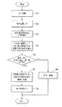
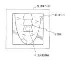
次に、本実施例の動作を図6を参照して説明する。まず、切片を撮像する(ステップS1)。すると、例えば図7に示す画像データ2aが得られる。このとき、通常の蛍光燈や白熱燈ではなく、インバータ方式の照明を用いると、干渉色を良好に撮影することができる。図7に示す例では、ミクロトームのボート40に複数の試料Sが浮遊している。次いで、膜厚を測定する切片の位置を入力する(ステップS2)。ここでは、ボートの中心にある試料Sを切片位置として入力したとする。すると、設定部5は、切片測定領域Rを特定する。ここでは、切片測定領域を円形としている。この切片測定領域を特定するための設定は、図8に示す設定ウインドウ5aを表示部30に表示し、このラジオボタンや入力セルへの指定に基づいて行う。図8中測定エリアとあるのは、切片測定領域を意味する。
【0036】
さらに、計測部6は、この切片測定領域の平均色を算出する(ステップS3)。さらに、平均色を基準として、切片測定領域内の各画素の色の誤差を上述した式(1)により算出する(ステップS4)。
【0037】
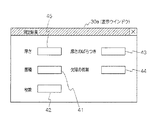
ここで、当該切片測定領域内の各画素の誤差のうち最も小さい誤差の値が、予め定められたしきい値以下か否かを判定する(ステップS5)。予め定められたしきい値以上の場合には、膜厚が均一でないため、エラー処理を行う(ステップS6)。一方、しきい値以下の場合には、その最も誤差が小さかった画素の色情報を図4に示す厚さ情報に変換する(ステップS7)。さらに、この厚さ情報を外部出力する(ステップS8)。この厚さ情報の出力は、例えば、図9に示す表示ウインドウ30aにより行う。図9に示す例では、表示ウインドウ30aの左上のセル45に厚さの値を表示出力する。
【0038】
このようにCRT上に膜厚の計測結果を出力すると共に、必要に応じてプリンタに印刷し、あるいは画像記録部14にメモリーする。
【0039】
さらに、また、実施例によっては、図9に示す各種情報を計測して表示するようにしても良い。図9に示す例では、測定対象となった領域の膜厚を表示する厚さ表示セル45と、膜厚測定対象物の位置指定したエリア内の膜厚のばらつきを表示する厚さのばらつき表示セル43と、膜厚測定対象物の位置指定した位置の試料の面積を表示する面積表示セル41と、膜厚測定対象物の位置指定した位置の試料の欠損の有無を表示する欠損表示セル44と、稼働時に切削された試料の枚数を表示する枚数カウント表示セル42とを備えている。
【0040】
この例では、エッジの抽出により切片の外形を特定する。このエッジの抽出に際して、空間微分処理などを前処理として行うことで、エッジを強調するようにしてもよい。このエッジの抽出を良好に行うため、切片の背景となる部分を濃度の濃い色としたり、また、特徴的な反射をする材質で背景部分を構成するようにしても良い。
【0041】
エッジで閉空間が形成されている場合、これをラベリングし、切片として扱う。また、この撮像を一定時間毎に行いラベリングした切片の移動を追跡することで、切片の数をカウントしていくことができる。
【0042】
図7に示すような長方形の切片では、画像のエッジから閉じた空間を抽出してその4角の座標を特定すると、その切片の面積を容易に求めることができる。さらに、エッジで囲まれた部分があるにもかかわらず、この領域が一定面積以下の場合には、切片が折り畳まれてしまったか、または切削時に欠損が生じたと判定できる。
【0043】
厚さのばらつきについては、色分布評価手段8による評価結果に基づいて判定することができる。
【0044】
【発明の効果】
本発明は以上のように構成され機能するので、これによると、色分布評価手段が、切片測定領域の色情報を各画素毎に読み出すと共に当該領域内の色の分布を評価し、変換処理手段が、色分布評価手段によって評価された色の分布から当該切片の標準的な色を特定すると共に当該特定色の色情報を厚さ情報に変換するため、当該切片の標準的な膜厚を計測することができ、しかも、色情報を厚さ情報に変換することで計測するため、環境や観測者の変化にかかわらず、長期間に渡り定量的に膜厚を測定することができ、しかも、画像処理により膜厚を測定するため、干渉色をデジタル信号として扱うことができ、このため、目視による場合と比較して極めて精度良く膜厚を測定することができる従来にない優れた膜厚計測装置を提供することができる。
【図面の簡単な説明】
【図1】本発明の一実施形態の構成を示すブロック図である。
【図2】図1に示した計測部の詳細構成を示すブロック図である。
【図3】本発明の一実施例の構成を示すブロック図である。
【図4】図3に示した計測部が用いる変換テーブルの一例を示す説明図である。
【図5】図3に示した実施例のハードウエア資源の構成を示すブロック図である。
【図6】図3に示す実施例の動作を示すフローチャートである。
【図7】図6に示すステップS1で撮像した画像データの一例を示す説明図である。
【図8】図6に示す切片測定領域の特定で用いる測定位置等の設定を行う設定ウインドウを例示する説明図である。
【図9】図6で示す計測結果の表示に用いる表示ウインドウの一例を示す説明図である。
【符号の説明】
2 撮像手段
4 切片位置特定部
6 計測部
8 色分布評価手段
10 変換処理手段
12 エラー処理機能
14 平均色算出機能
16 誤差算出機能
18 誤差別特定機能[0001]
BACKGROUND OF THE INVENTION
The present invention relates to a film thickness measuring apparatus, and more particularly, to a film thickness measuring apparatus that measures the thickness of a sample using an interference color. A sample such as a biological specimen is obtained by cutting a specimen using, for example, an ultramicrotome. In the present invention, in addition to a biological specimen, the film thickness of any substance that expresses an interference color is an object of measurement.
[0002]
[Prior art]
Conventionally, the measurement of the thickness of the slice of the sample has been performed by the examiner directly viewing the interference color through an eyepiece of an optical microscope. Since the interference color of the thin film changes abruptly with respect to the change in the thickness of the thin film, the thickness of several nanometers to several tens of nanometers can be specified by judging the color of the visual measurement.
[0003]
[Problems to be solved by the invention]
However, visual observation of interference colors using an optical microscope has a disadvantage that many of them are judgments based on experience, so that it is difficult to make a uniform judgment and an error is caused by an inspector.
[0004]
That is, the visual inspection has the disadvantage that the inspection results vary depending on the experience and physical condition of the inspector, and it is difficult to accurately determine the film thickness.
[0005]
In addition, if the color sample used as a reference has been used for many years, color deterioration occurs due to fading, and the reference itself changes due to dirt, which also makes it difficult to accurately measure the film thickness.
[0006]
Further, in the measurement of the interference color by visual observation, it is difficult to determine the change in thickness in one section according to the area. Therefore, in the conventional example, the film thickness itself and the distribution of film thickness in the section are determined. There was a disadvantage that it could not be quantified.
[0007]
On the other hand, in today's technology, there are an increasing number of cases in which various visual inspections are automated by image processing. However, the measurement of the film thickness by interference color is not known and needs to be newly developed. In this case, when the interference color in the slice is not uniform, how to specify the film thickness with high accuracy and increase in processing speed are specific development issues. Another problem is how to specify the position of the slice in the image.
[0008]
OBJECT OF THE INVENTION
An object of the present invention is to provide a film thickness measuring apparatus that can improve the disadvantages of the conventional example, and in particular, can measure the film thickness of a section quantitatively by image processing.
[0009]
[Means for Solving the Problems]
Therefore, in the present invention, an imaging unit that images a section of a sample, a section position specifying unit that specifies a region where the section is located in the image data output from the imaging unit as a section measurement region, and the section position specification And a measurement unit that calculates the thickness of the section based on the color information of the section measurement region specified by the section.
In addition, the measurement unit reads out the color information of the section measurement region specified by the section position specifying unit for each pixel and evaluates the color distribution in the region, and the color distribution evaluation unit performs evaluation. A configuration is adopted in which a standard color of the slice is specified from the determined color distribution, and conversion processing means for converting the color information of the specified color into thickness information is provided. As a result, the above-described purpose is achieved.
[0010]
The measurement unit calculates the thickness of the section based on the color information of the section measurement region specified by the section position specifying unit. At this time, the color distribution evaluation unit reads out the color information of the section measurement region for each pixel and evaluates the color distribution in the region. For example, if the sample sections have the same thickness, the color distribution will be almost uniform, but if there is any malfunction during cutting such as an ultramicrotome, the film thickness will not be uniform. Widen color distribution. Therefore, the color distribution evaluation means evaluates whether the film thickness is uniform. Further, the conversion processing unit specifies a standard color of the segment from the color distribution evaluated by the color distribution evaluation unit and converts the color information of the specific color into thickness information. For this reason, the standard film thickness of the section is measured.
[0011]
DETAILED DESCRIPTION OF THE INVENTION
Hereinafter, embodiments of the present invention will be described with reference to the drawings.
[0012]
FIG. 1 is a block diagram showing the configuration of a film thickness measuring apparatus according to the present invention. The film thickness measuring apparatus includes an imaging unit 2 that images a section of a sample, a section
[0013]
In addition, the measuring unit 6 reads out color information of the section measurement region specified by the section
[0014]
The imaging means 2 images a slice of a thin film cut by an ultramicrotome or the like. Depending on the configuration of the microtome, the boat portion where the section floats may be imaged.
[0015]
The section
[0016]
The measurement unit 6 may be configured to include conversion data in which the relationship between the interference color and the film thickness is defined in advance. This data has various modes, and is created according to the gradation handled by the imaging means, the required film thickness accuracy, and the like.
[0017]
The color distribution evaluation means 8 evaluates the color distribution in the section measurement area. Specifically, using a statistical method, a color difference that appears in each pixel in the section measurement region is evaluated numerically. For example, after calculating the average color, calculate the error of each pixel using this average color as a reference, calculate the standard deviation, and calculate the rate of color change in adjacent pixels Evaluation is performed by the method of
[0018]
This evaluation is useful in two ways, firstly it helps to identify standard colors within the slice, thereby eliminating the effects of noise. Secondly, if the distribution is too wide, it means that the film thickness has changed extremely, so that it can be used to determine that the use as an intercept is impossible.
[0019]
The
[0020]
Next, an example in which the film thickness measurement is stopped by the evaluation of the color
[0021]
Next, an embodiment in which the color distribution is evaluated based on errors will be described. As shown in FIG. 2, in this embodiment, the color
[0022]
The conversion processing means 10 includes an error-specific specifying
[0023]
In this error example, the error processing function 12 performs error processing when the smallest error exceeds a predetermined threshold value.
[0024]
【Example】
FIG. 3 is an explanatory diagram showing the configuration of an embodiment of the present invention. In the embodiment shown in FIG. 3, the imaging means 2 includes a CCD camera 22 for imaging a film thickness measurement object, an A /
[0025]
In addition, an
[0026]
In the present embodiment, the section position specifying unit is defined as a
[0027]
In this embodiment, since the slice measurement area has a simple shape such as a circle or a square to speed up the process, the slice measurement area specifying function is a circle configured with a radius of a predetermined number of pixels from the measurement position. Is a section measurement region, and a quadrangle surrounded by four sides of a predetermined number of pixels centered on the measurement position.
[0028]
Here, a
[0029]
The measuring unit 6 obtains an average value of the color data from the image data stored in the image storage unit 14. When the image data is RGB color data, an average value is calculated for each RGB.
[0030]
The conversion processing means 10 of the measurement unit 6 measures the color data of the image whose position is specified for the film thickness measurement object, and calculates the average value of the color data from the measurement result. Next, an error from the average value is calculated for each pixel (dot) in the measurement target region. When the average of RGB is Ra, Ga, and Ba, the error e for each pixel (dot) in the intercept measurement region is expressed by the following equation (1).
[0031]
e 2 = (Ra−R) 2 + (Ga−G) 2 + (Ba−B) 2 ... Formula (1)
[0032]
Based on the color of the pixel with the smallest error e, the thickness A is obtained with reference to the conversion table shown in FIG.
[0033]
FIG. 5 is a block diagram showing the configuration of the hardware resources of this embodiment. The
[0034]
Such a program can be stored and distributed in a storage medium such as a CD-ROM or a floppy disk.
[0035]
Next, the operation of this embodiment will be described with reference to FIG. First, a section is imaged (step S1). Then, for example, image data 2a shown in FIG. 7 is obtained. At this time, if an inverter type illumination is used instead of a normal fluorescent lamp or incandescent lamp, the interference color can be photographed satisfactorily. In the example shown in FIG. 7, a plurality of samples S are floating on the microtome boat 40. Next, the position of the section for measuring the film thickness is input (step S2). Here, it is assumed that the sample S at the center of the boat is input as the intercept position. Then, the
[0036]
Furthermore, the measuring unit 6 calculates the average color of this section measurement region (step S3). Further, using the average color as a reference, the color error of each pixel in the intercept measurement region is calculated by the above-described equation (1) (step S4).
[0037]
Here, it is determined whether or not the smallest error value among the errors of each pixel in the intercept measurement region is equal to or less than a predetermined threshold value (step S5). If the threshold value is equal to or greater than the predetermined threshold, the film thickness is not uniform, and error processing is performed (step S6). On the other hand, if it is equal to or less than the threshold value, the color information of the pixel having the smallest error is converted into the thickness information shown in FIG. 4 (step S7). Further, the thickness information is output to the outside (step S8). The thickness information is output by, for example, the display window 30a shown in FIG. In the example shown in FIG. 9, the thickness value is displayed and output in the upper
[0038]
In this manner, the film thickness measurement result is output on the CRT, and printed on a printer as necessary, or stored in the image recording unit 14.
[0039]
Furthermore, depending on the embodiment, various information shown in FIG. 9 may be measured and displayed. In the example shown in FIG. 9, a
[0040]
In this example, the outline of the slice is specified by extracting the edge. When extracting the edge, the edge may be emphasized by performing a spatial differentiation process or the like as a pre-process. In order to satisfactorily extract the edge, the background portion of the slice may be a dark color, or the background portion may be made of a material that has a characteristic reflection.
[0041]
If the closed space is formed by the edge, it is labeled and treated as an intercept. In addition, the number of sections can be counted by performing this imaging at regular intervals and tracking the movement of the labeled sections.
[0042]
In the rectangular segment as shown in FIG. 7, if the closed space is extracted from the edge of the image and the coordinates of the four corners are specified, the area of the segment can be easily obtained. Furthermore, even if there is a portion surrounded by an edge, if this region is less than a certain area, it can be determined that the section has been folded or a defect has occurred during cutting.
[0043]
The thickness variation can be determined based on the evaluation result by the color distribution evaluation means 8.
[0044]
【The invention's effect】
Since the present invention is configured and functions as described above, according to this, the color distribution evaluation unit reads out the color information of the intercept measurement region for each pixel, evaluates the color distribution in the region, and performs the conversion processing unit. However, in order to identify the standard color of the section from the color distribution evaluated by the color distribution evaluation means and convert the color information of the specific color into thickness information, the standard film thickness of the section is measured. In addition, since the color information is measured by converting the thickness information into thickness information, the film thickness can be measured quantitatively over a long period of time, regardless of changes in the environment or the observer. Since the film thickness is measured by image processing, the interference color can be handled as a digital signal, which makes it possible to measure the film thickness with extremely high accuracy compared to visual observation. Providing equipment It can be.
[Brief description of the drawings]
FIG. 1 is a block diagram showing a configuration of an embodiment of the present invention.
FIG. 2 is a block diagram illustrating a detailed configuration of a measurement unit illustrated in FIG.
FIG. 3 is a block diagram showing a configuration of an embodiment of the present invention.
4 is an explanatory diagram illustrating an example of a conversion table used by a measurement unit illustrated in FIG. 3;
FIG. 5 is a block diagram showing a configuration of hardware resources of the embodiment shown in FIG. 3;
6 is a flowchart showing the operation of the embodiment shown in FIG. 3;
7 is an explanatory diagram showing an example of image data captured in step S1 shown in FIG.
8 is an explanatory view exemplifying a setting window for setting a measurement position and the like used for specifying the section measurement region shown in FIG. 6;
FIG. 9 is an explanatory diagram showing an example of a display window used for displaying the measurement result shown in FIG. 6;
[Explanation of symbols]
2
Claims (3)
前記計測部が、前記切片位置特定部によって特定された切片測定領域の色情報を各画素毎に読み出すと共に当該領域内の色の分布を評価する色分布評価手段と、この色分布評価手段によって評価された色の分布から当該切片の標準的な色を特定すると共に当該特定した色の色情報を厚さ情報に変換する変換処理手段とを備えたことを特徴とする膜厚測定装置。An imaging unit that images a section of the sample, a section position specifying unit that specifies a region where the section is located in the image data output from the imaging unit as a section measurement region, and a section specified by the section position specifying unit A measurement unit that calculates the thickness of the section based on the color information of the measurement region,
The measurement unit reads out color information of the section measurement region specified by the section position specifying unit for each pixel and evaluates the color distribution in the region, and the color distribution evaluation unit evaluates the color distribution evaluation unit. A film thickness measuring apparatus comprising: a conversion processing unit that specifies a standard color of the slice from the color distribution and converts the color information of the specified color into thickness information.
前記変換処理手段が、前記誤差算出機能によって算出された誤差が最も小さい画素の色情報を当該切片測定領域の標準的な特定色とする誤差別特定機能とを備えたことを特徴とする請求項1記載の膜厚測定装置。The color distribution evaluation unit calculates an average value of color information in the segment measurement region, and an average color calculated by the average color calculation function is used as a reference in the segment measurement region. With an error calculation function that calculates an error for each pixel,
The conversion processing unit includes an error-specific specifying function that sets color information of a pixel with the smallest error calculated by the error calculating function as a standard specific color of the intercept measurement region. 1. The film thickness measuring apparatus according to 1.
Priority Applications (1)
| Application Number | Priority Date | Filing Date | Title |
|---|---|---|---|
| JP05980697A JP3745075B2 (en) | 1997-02-27 | 1997-02-27 | Film thickness measuring device |
Applications Claiming Priority (1)
| Application Number | Priority Date | Filing Date | Title |
|---|---|---|---|
| JP05980697A JP3745075B2 (en) | 1997-02-27 | 1997-02-27 | Film thickness measuring device |
Publications (2)
| Publication Number | Publication Date |
|---|---|
| JPH10239027A JPH10239027A (en) | 1998-09-11 |
| JP3745075B2 true JP3745075B2 (en) | 2006-02-15 |
Family
ID=13123868
Family Applications (1)
| Application Number | Title | Priority Date | Filing Date |
|---|---|---|---|
| JP05980697A Expired - Fee Related JP3745075B2 (en) | 1997-02-27 | 1997-02-27 | Film thickness measuring device |
Country Status (1)
| Country | Link |
|---|---|
| JP (1) | JP3745075B2 (en) |
Families Citing this family (4)
| Publication number | Priority date | Publication date | Assignee | Title |
|---|---|---|---|---|
| JP4615400B2 (en) * | 2005-09-02 | 2011-01-19 | パナソニック株式会社 | Membrane measuring device for porous membrane on battery electrode plate and coating device using the same |
| JP2011191252A (en) * | 2010-03-16 | 2011-09-29 | Nippon Steel Engineering Co Ltd | Surface quality evaluation method of metal and surface quality evaluation apparatus of metal |
| JP5318303B1 (en) * | 2013-01-31 | 2013-10-16 | 株式会社ニレコ | Battery electrode plate film measuring apparatus and film measuring method |
| CN105758318A (en) * | 2016-02-25 | 2016-07-13 | 深圳市众诚达应用材料科技有限公司 | System and method for detecting CdS film thickness based on machine vision color difference method |
-
1997
- 1997-02-27 JP JP05980697A patent/JP3745075B2/en not_active Expired - Fee Related
Also Published As
| Publication number | Publication date |
|---|---|
| JPH10239027A (en) | 1998-09-11 |
Similar Documents
| Publication | Publication Date | Title |
|---|---|---|
| KR100442071B1 (en) | Nondestructive inspection method and an apparatus thereof | |
| WO2013187206A1 (en) | Image processing device, image processing method, and image processing program | |
| CN106596073A (en) | Method and system for detecting image quality of optical system, and testing target plate | |
| WO2019059011A1 (en) | Training data creation method and device, and defect inspecting method and device | |
| CN112033965B (en) | 3D arc surface defect detection method based on differential image analysis | |
| JP3581149B2 (en) | Method and apparatus for identifying an object using a regular sequence of boundary pixel parameters | |
| CN111047568A (en) | Steam leakage defect detection and identification method and system | |
| JP2001266121A (en) | Method for diagnosing deterioration of coating on coated steel product | |
| JP3884834B2 (en) | Defect inspection method and apparatus | |
| KR101146081B1 (en) | Detection of macro-defects using micro-inspection inputs | |
| CN108445010A (en) | Automatic optical detection method and device | |
| EP1986155A2 (en) | Specimen analysis and acicular region analyzer | |
| US6404846B1 (en) | Fluorescent x-ray method for determining x-ray alignment by luminescent changes | |
| JP3324699B2 (en) | Method and apparatus for measuring fiber diameter distribution | |
| JP3745075B2 (en) | Film thickness measuring device | |
| CN106204523A (en) | A kind of image quality evaluation method and device | |
| JPH08505478A (en) | Method and associated apparatus for controlling the surface condition of one side of a solid | |
| JP2001314374A (en) | Corneal endothelial cell measuring apparatus | |
| JP2007104296A (en) | Method, apparatus, and program for measuring resolution | |
| JPS5830049B2 (en) | Automatic reticulocyte measurement device | |
| JP4061760B2 (en) | Particle image segmentation method | |
| WO2020130786A1 (en) | A method of analyzing visual inspection image of a substrate for corrosion determination | |
| EP4010873B1 (en) | Use of an hdr image in a visual inspection process | |
| KR101032917B1 (en) | Hole cluster test method | |
| JP2638121B2 (en) | Surface defect inspection equipment |
Legal Events
| Date | Code | Title | Description |
|---|---|---|---|
| A621 | Written request for application examination |
Free format text: JAPANESE INTERMEDIATE CODE: A621 Effective date: 20040223 |
|
| A977 | Report on retrieval |
Free format text: JAPANESE INTERMEDIATE CODE: A971007 Effective date: 20050927 |
|
| TRDD | Decision of grant or rejection written | ||
| A01 | Written decision to grant a patent or to grant a registration (utility model) |
Free format text: JAPANESE INTERMEDIATE CODE: A01 Effective date: 20051025 |
|
| A61 | First payment of annual fees (during grant procedure) |
Free format text: JAPANESE INTERMEDIATE CODE: A61 Effective date: 20051116 |
|
| R150 | Certificate of patent or registration of utility model |
Free format text: JAPANESE INTERMEDIATE CODE: R150 |
|
| FPAY | Renewal fee payment (event date is renewal date of database) |
Free format text: PAYMENT UNTIL: 20091202 Year of fee payment: 4 |
|
| FPAY | Renewal fee payment (event date is renewal date of database) |
Free format text: PAYMENT UNTIL: 20091202 Year of fee payment: 4 |
|
| FPAY | Renewal fee payment (event date is renewal date of database) |
Free format text: PAYMENT UNTIL: 20101202 Year of fee payment: 5 |
|
| FPAY | Renewal fee payment (event date is renewal date of database) |
Free format text: PAYMENT UNTIL: 20111202 Year of fee payment: 6 |
|
| FPAY | Renewal fee payment (event date is renewal date of database) |
Free format text: PAYMENT UNTIL: 20121202 Year of fee payment: 7 |
|
| FPAY | Renewal fee payment (event date is renewal date of database) |
Free format text: PAYMENT UNTIL: 20131202 Year of fee payment: 8 |
|
| R250 | Receipt of annual fees |
Free format text: JAPANESE INTERMEDIATE CODE: R250 |
|
| R250 | Receipt of annual fees |
Free format text: JAPANESE INTERMEDIATE CODE: R250 |
|
| LAPS | Cancellation because of no payment of annual fees |