JP3740426B2 - Driving device for wheeled work vehicle - Google Patents
Driving device for wheeled work vehicle Download PDFInfo
- Publication number
- JP3740426B2 JP3740426B2 JP2002062491A JP2002062491A JP3740426B2 JP 3740426 B2 JP3740426 B2 JP 3740426B2 JP 2002062491 A JP2002062491 A JP 2002062491A JP 2002062491 A JP2002062491 A JP 2002062491A JP 3740426 B2 JP3740426 B2 JP 3740426B2
- Authority
- JP
- Japan
- Prior art keywords
- motor
- generator
- rotational speed
- variable displacement
- prime mover
- Prior art date
- Legal status (The legal status is an assumption and is not a legal conclusion. Google has not performed a legal analysis and makes no representation as to the accuracy of the status listed.)
- Expired - Fee Related
Links
- 238000006073 displacement reaction Methods 0.000 claims description 71
- 239000000446 fuel Substances 0.000 claims description 34
- 238000002347 injection Methods 0.000 claims description 31
- 239000007924 injection Substances 0.000 claims description 31
- 239000003921 oil Substances 0.000 description 17
- 230000003247 decreasing effect Effects 0.000 description 10
- 238000010586 diagram Methods 0.000 description 8
- 230000000694 effects Effects 0.000 description 4
- 238000000034 method Methods 0.000 description 4
- 230000007423 decrease Effects 0.000 description 3
- 230000005611 electricity Effects 0.000 description 3
- 239000003990 capacitor Substances 0.000 description 1
- 238000012544 monitoring process Methods 0.000 description 1
- 230000007935 neutral effect Effects 0.000 description 1
- 239000004576 sand Substances 0.000 description 1
- 238000011144 upstream manufacturing Methods 0.000 description 1
Images


Classifications
-
- Y—GENERAL TAGGING OF NEW TECHNOLOGICAL DEVELOPMENTS; GENERAL TAGGING OF CROSS-SECTIONAL TECHNOLOGIES SPANNING OVER SEVERAL SECTIONS OF THE IPC; TECHNICAL SUBJECTS COVERED BY FORMER USPC CROSS-REFERENCE ART COLLECTIONS [XRACs] AND DIGESTS
- Y02—TECHNOLOGIES OR APPLICATIONS FOR MITIGATION OR ADAPTATION AGAINST CLIMATE CHANGE
- Y02T—CLIMATE CHANGE MITIGATION TECHNOLOGIES RELATED TO TRANSPORTATION
- Y02T10/00—Road transport of goods or passengers
- Y02T10/60—Other road transportation technologies with climate change mitigation effect
- Y02T10/62—Hybrid vehicles
-
- Y—GENERAL TAGGING OF NEW TECHNOLOGICAL DEVELOPMENTS; GENERAL TAGGING OF CROSS-SECTIONAL TECHNOLOGIES SPANNING OVER SEVERAL SECTIONS OF THE IPC; TECHNICAL SUBJECTS COVERED BY FORMER USPC CROSS-REFERENCE ART COLLECTIONS [XRACs] AND DIGESTS
- Y02—TECHNOLOGIES OR APPLICATIONS FOR MITIGATION OR ADAPTATION AGAINST CLIMATE CHANGE
- Y02T—CLIMATE CHANGE MITIGATION TECHNOLOGIES RELATED TO TRANSPORTATION
- Y02T10/00—Road transport of goods or passengers
- Y02T10/60—Other road transportation technologies with climate change mitigation effect
- Y02T10/7072—Electromobility specific charging systems or methods for batteries, ultracapacitors, supercapacitors or double-layer capacitors
Landscapes
- Hybrid Electric Vehicles (AREA)
- Control Of Vehicle Engines Or Engines For Specific Uses (AREA)
- Electric Propulsion And Braking For Vehicles (AREA)
Description
【0001】
【発明の属する技術分野】
本発明はホイールローダ等のホイール式作業用車両の駆動装置に係わり、特に、可変容量型油圧ポンプと可変容量型油圧モータを一対の主管路により閉回路接続し、可変容量型油圧ポンプから吐出された圧油により可変容量型油圧モータを駆動し、可変容量型油圧モータの駆動により車輪を駆動し走行動作させる油圧走行駆動装置を備えたホイール式作業用車両の駆動装置に関する。
【0002】
【従来の技術】
ホイールローダ等のホイール式作業用車両の駆動装置としては、例えば特開平6−58412号公報に記載されているような油圧駆動方式が実用化されている。また、特開平11−158937号公報に記載のような電動駆動方式も検討されている。
【0003】
特開平6−58412号公報に記載の油圧式の駆動装置は、可変容量型油圧ポンプと可変容量型油圧モータを一対の主管路により閉回路接続し、可変容量型油圧ポンプから吐出された圧油により可変容量型油圧モータを駆動し、可変容量型油圧モータの駆動により車輪を駆動し走行動作させるものである。可変容量型油圧ポンプの動力源はエンジンであり、アクセルペダルの操作量を増大させるとエンジン回転数が増大し、可変容量型油圧ポンプの吐出流量が増大するため、可変容量型油圧モータの回転数も増大し、走行速度が速くなる。アクセルペダルの操作量を減少させるとエンジン回転数は減少し、可変容量型油圧ポンプの吐出流量が減少するため、可変容量型油圧モータの回転数も減少し、走行速度が遅くなる。
【0004】
また、車両の走行中にアクセルペダルを緩め操作してエンジン回転数を低下させると、可変容量型油圧ポンプの吐出流量が低下する一方、可変容量型油圧モータが慣性で回転を続けるので、可変容量型油圧モータの吐出流量が可変容量型油圧ポンプの吐出流量よりも大きくなって可変容量型油圧モータの吐出圧が上昇する。いわゆるブレーキ圧力が発生する。このブレーキ圧力によって可変容量型油圧ポンプはモータとして作用し、エンジンを駆動することになる。すなわち、エンジンブレーキが作用し、減速時に車両の運動エネルギーをエンジンの回転をアシストするという形で回収作用を行う。
【0005】
特開平11−158937号公報に記載の電動式の駆動装置は、エンジンの駆動によって発電機と油圧ポンプが駆動され、走行については発電機によって発電した電力により電動モータが駆動され、この電動モータの駆動により車体を走行駆動させる方式である。
【0006】
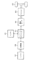
また、このような駆動方式において用いる電動モータは、通常、交流式の電動モータであるため、インバータを必要とする。また、無走行時等の軽負荷時に余った電力を蓄え、走行時等の重負荷時に利用するため電力を蓄えるバッテリも必要となる。そのような機器を配置したシステムの一例を図7に示す。
【0007】
図7において、エンジン201の駆動により発電機208が駆動され、電力を発生する。発電機208により発生した電力は、インバータ/コンバータ280によりバッテリ281に蓄えられる制御とバッテリ281の電力により電動モータ282を駆動させる制御が行われ、電動モータ282が駆動される。この電動モータ282の駆動によりミッション283が駆動され、車輪250が駆動し、車体が前・後進動作する。
【0008】
以上の構成からなる電動モータによる駆動方式では、車両減速時において、電動モータ282を発電機として作動させ、車両減速時の運動エネルギーを電力として回収し、インバータ/コンバータ280によりバッテリ281に蓄える。回収した電力は、走行駆動時に電動モータ282を騒動させるために使用される。
【0009】
【発明が解決しようとする課題】
しかしながら、上記従来技術には次のような問題がある。
【0010】
特開平6−58412号公報に記載の油圧式の駆動装置では、車両減速時の運動エネルギーをその車両減速時にエンジン回転をアシストするという形で回収する方式であり、車両減速時ではない通常走行時や走行・作業時には、その回収したエネルギーを利用することはできない。
【0011】
特開平11−158937号公報に記載の電動式の駆動装置では、それを図7に示すシステムのように構成した場合は、車両減速時の運動エネルギーを電力として回収し、通常走行時或いは走行・作業時にその回収したエネルギーを利用することが可能である。しかし、図7に示すシステムでは、ホイールローダ等の重量の大きな作業用車両の走行を電動モータのみで行うので、高出力の電動モータが必要となり、電動モータの値段が高価となり、車両価格を高価とせざるを得なくなる。
【0012】
本発明の目的は、必要機器の価格を抑え、車両減速時の運動エネルギーを回収し、通常走行時や走行・作業時等の必要時にその回収したエネルギーを利用することができるホイール式作業用車両の駆動装置を提供することである。
【0013】
【課題を解決するための手段】
(1)上記目的を達成するために、本発明は、前記アクセル操作手段の非操作時或いは操作量の減少時に前記発電機/モータを発電機として駆動しかつ発生した電力を前記蓄電装置に蓄え、前記アクセル操作手段の操作時に、その蓄電装置に蓄えた電力により前記発電機/モータをモータとして駆動し、前記原動機と前記発電機/モータの両方の動力で前記軸の回転数を前記アクセル操作手段が設定する目標回転数まで上げる制御を行う制御手段とを備え、前記制御手段は、前記アクセル操作手段の操作時に、前記蓄電装置の蓄電量が十分にあるときは前記モータとして駆動する発電機/モータの回転数を前記アクセル操作手段が設定する目標回転数まで上げ、かつ前記原動機の回転数が最低回転数となるよう原動機に供給される燃料噴射量を制御する制御を行うとともに、前記モータとして駆動する発電機/モータの最大回転数が前記アクセル操作手段が設定する目標回転数に足りないときは前記原動機の燃料噴射量を増やし 原動機の回転数を前記目標回転数まで上げる制御を行い、前記蓄電装置の蓄電量が十分でないときは前記原動機の燃料噴射量を増やし原動機の回転数を前記アクセル操作手段が設定する目標回転数まで上げる制御を行うものとする。
【0014】
以上のように構成した本発明においては、作業用車両の走行途中にオペレータが作業用車両の減速を意図してアクセル操作手段の操作を止める或いは操作量を減少させると、慣性で回転を続けようとする可変容量型油圧モータの吐出圧が上昇し、可変容量型油圧ポンプがモータとして作用する一方、制御手段は発電機/モータを発電機として駆動し、この発電機/モータがモータとして作用する可変容量型油圧ポンプの動力により回転駆動され電力を発生し、その電力が蓄電装置に蓄えられる。つまり、車両減速時に作業用車両の運動エネルギーで発電機/モータを駆動し、発生した電力を蓄電装置に蓄えるという形で運動エネルギーの回収を行う。
【0015】
オペレータがアクセル操作手段を操作する通常走行時或いは走行・作業時は、制御手段は発電機/モータをモータとして駆動するよう切り換え、原動機と可変容量型油圧ポンプとを連結する軸の回転数を原動機と発電機/モータの両方の動力で目標回転数となるよう制御するため、通常走行時或いは走行・作業時に、車両減速時に回収したエネルギー(蓄電装置に蓄えた電力)を有効利用することができる。また、原動機と発電機/モータの両方の動力で原動機と可変容量型油圧ポンプとを連結する軸を回転駆動するので、発電機/モータは高出力を必要とせず、必要機器の価格を抑えることができる。
【0016】
また、アクセル操作手段の操作時(通常走行時或いは走行・作業時)に原動機と発電機/モータの両方の動力で原動機と可変容量型油圧ポンプとを連結する軸を回転駆動するとき、蓄電装置の蓄電量が十分にあるときは発電機/モータによる駆動が優先され、原動機の回転数が最低回転数となるよう燃料噴射量を制御して原動機の燃料消費を抑えるため、最大の省エネ効果が得られる。そして、発電機/モータの最大回転数が前記アクセル操作手段が設定する目標回転数に足りないときは前記原動機の燃料噴射量を増やし原動機の回転数を前記目標回転数まで上げる制御を行うので、発電機/モータは原動機の回転をアシスト的に制御するものとなり、発電機/モータを小型化し、必要機器の価格を更に抑えることができる。
【0017】
さらに、前記蓄電装置の蓄電量が十分でないときは前記原動機の燃料噴射量を増やし原動機の回転数を前記アクセル操作手段が設定する目標回転数まで上げる制御を行うので、通常走行時或いは走行・作業時に、蓄電装置の蓄電量に応じて可変容量型油圧ポンプの駆動方式を切り換え、蓄電装置の蓄電量が少ないときでも確実に走行駆動することができる。
【0022】
【発明の実施の形態】
以下、本発明の実施の形態を図面を用いて説明する。
【0023】
まず、本発明の第1の実施の形態を図1〜図5により説明する。
【0024】
図1において、1は原動機、例えばディーゼルエンジン(以下単にエンジンという)であり、燃料噴射量制御装置10を備え、燃料噴射量を制御することによりエンジン回転数が制御される。エンジン1は軸11により可変容量型油圧ポンプ2と油圧ポンプ3とチャージポンプ4に連結され、軸11によりエンジン1の動力が可変容量型油圧ポンプ2と油圧ポンプ3とチャージポンプ4に伝達され、それらを駆動する。
【0025】
可変客量型油圧ポンプ2は一対の主管路20,21を介して可変容量型油圧モータ5に閉回路接続され、油圧ポンプ2から吐出された圧油は油圧モータ5に供給されて油圧モータ5を駆動し、油圧モータ5から排出された圧油は油圧ポンプ2に戻される。可変容量型油圧モータ5は走行モータであり、車輪50を回転駆動する。
【0026】
油圧ポンプ3から吐出された圧油はコントロールバルブ6を介し、ステアリングシリンダ60、アームシリンダ61、バケットシリンダ62に供給され、これらを駆動する。
【0027】
チャージポンプ4から吐出された圧油は可変容量型油圧ポンプ2の吐出容量を制御するのに用いられる。すなわち、チャージポンプ4の吐出油は、その一部が絞り40を介して前後進切換弁42に導かれる一方で、残りが絞り40を通過することなく前後進切換弁42に直接導かれ、さらにこれら吐出油は前後進切換弁42の切り換え位置に応じて管路43a,43bを介し、傾転シリンダ44の油室に案内される。チャージポンプ4の吐出流量に応じて絞り40の上流側と下流側との間の差圧(絞り40の前後差圧)が変化し、この差圧によって傾転シリンダ44が駆動されて可変容量型油圧ポンプ2の傾転角が変化し、吐出容量が増減する。
【0028】
前後進切換弁42がF位置の時には、傾転シリンダ44が44cの位置となり、主管路20に圧油が吐出されて車両が前進し、前後進切換弁42がR位置の時には、傾転シリンダ44が44aの位置となり、管路21に圧油が吐出されて車両が後進する。前後進切換弁42が中立位置の時には、傾転シリンダ44が44bの位置となり、可変容量型油圧ポンプ2の吐出容量が零となる。
【0029】
また、絞り40の前後差圧は、前後進切換弁42を介して管路43a,43bに導かれ、3位置形の圧力選択弁45を切り換え制御する。前後進切換弁42がF位置のときには圧力選択弁45が45aの位置に切り換わり、可変容量型油圧ポンプ2の吐出圧が主管路20から圧力選択弁45を介して管路46に導かれる。また、前後進切換弁42がR位置のときには圧力選択弁45が45cの位置に切り換わり、可変容量型油圧ポンプ2の吐出圧が主管路21から圧力選択弁45を介して管路46に導かれる。さらに、管路46の圧油は、サーボシリンダ48及び切換弁47に導かれる。
【0030】
サーボシリンダ48及び切換弁47は可変容量型油圧モータ5の吐出容量を制御するもので、圧力選択弁45を介し管路46により導かれた圧油の圧力が切換弁47の設定圧力以下のときは切換弁47が47aの位置に保持され、サーボシリンダ48のピストンの小径側側面のみに管路46により導かれた圧油の圧力が作用して、可変容量型油圧モータ5の吐出容量が最小値に設定される。圧力選択弁45を介し管路46により導かれた圧油の圧力が切換弁47の設定圧力以上のときは切換弁47が47bの位置に切り換えられ、サーボシリンダ48のピストンの大径側側面にも管路46により導かれた圧油の圧力が作用して、ピストンが左方向に移動し、可変容量型油圧モータ5の吐出容量が最大値に設定される。
【0031】
エンジン1を可変容量型油圧ポンプ2と油圧ポンプ3とチャージポンプ4に連結する軸11上には発電機/モータ8が配置されている。発電機/モータ8はインバータ/コンバータ80により発電機と電動モータのいずれかに切り換え制御される。
【0032】
発電機/モータ8が発電機として駆動する場合は、軸11のエンジン1と発電機/モータ8との間の軸部分11aによってエンジン1の動力(トルク)が発電機/モータ8に伝達され発電機/モータ8を回転駆動し、電力を発生する。また、可変容量型油圧ポンプ2がモータ駆動するときは、軸11の発電機/モータ8と可変容量型油圧ポンプ2との間の軸部分11bによって可変容量型油圧ポンプ2の動力(トルク)が発電機/モータ8に伝達され、発電機/モータ8はエンジンと発電機/モータ8の両方の動力によって回転駆動され、電力を発生する。
【0033】
発電機/モータ8が電動モータとして駆動する場合は、軸11の軸部分11bに動力(トルク)を伝達し、可変容量型油圧ポンプ2、油圧ポンプ3、チャージポンプ4を駆動する。つまり、この場合は、発電機/モータ8はエンジン1の動力(トルク)をアシストする動力補助手段として機能し、可変容量型油圧ポンプ2、油圧ポンプ3、チャージポンプ4はエンジン1と発電機/モータ8の両方の動力(トルク)で駆動される。
【0034】
発電機/モータ8が発電機として駆動する場合、発生した電力はインバータ/コンバータ80によりバッテリ81に蓄えられる。また、発電機/モータ8を電動モータとして駆動する場合は、バッテリ81の電力により駆動するようインバータ/コンバータ80により制御される。
【0035】
作業用車両の前進、後進を切り換える操作手段として走行指示切換装置70が設けられ、軸11の目標回転数を設定する操作手段としてアクセルペダル72が設けられている。走行指示切換装置70のレバー71の位置信号及びアクセルペダル72の操作量信号はコントローラ7に入力される。
【0036】
オペレータは、作業用車両を後進させる場合は、走行指示切換装置70のレバー71の位置を初期位置”N”の位置から”R”の位置に切り換え、作業用車両を前進させる場合は同レバー71の位置を”F”の位置に切り換える。コントローラ7は、走行指示切換装置70からの位置信号に基づき、レバー71の位置が”F”の位置の場合は、前後進切換弁42をF位置、レバー71の位置が”R”の位置の場合は、前後進切換弁42をR位置に切り換える。
【0037】
また、オペレータは、油圧モータ5の回転数を上げ走行速度を上げる場合或いはシリンダ61,62の駆動速度を速くし作業速度を上げる場合は、アクセルペダル72を操作し、軸11の目標回転数を増大させ、可変容量型油圧ポンプ2或いは油圧ポンプ3の回転数を上げる。コントローラ7は、アクセルペダル72からの操作量信号に基づき、エンジン1の燃料噴射量制御装置10を制御し、エンジン1の燃料噴射量を制御するとともに、インバータ/コンバータ80を制御し、発電機/モータ8及び発電機/モータ8とバッテリ81間の電力の授受を制御する。エンジン1の燃料噴射量を増大させると、エンジン1の回転数は増大し、燃料噴射量を減少させると、エンジン1の回転数は減少する。
【0038】
アクセルペダル72を操作したときのコントローラ70の処理機能を図2にフローチャートで示す。コントローラ70の処理機能は、概略的にいうと、アクセルペダル72の非操作時或いは操作量の減少時に発電機/モータ8を発電機として駆動しかつ発生した電力をバッテリ81に蓄え、アクセルペダル72の操作時に、そのバッテリ81に蓄えた電力により発電機/モータ8をモータとして駆動してその回転数をアクセルペダル72が設定する軸11の目標回転数まで上げかつエンジン1の回転数が低速回転数となるよう燃料噴射量制御装置10によりエンジン1に供給される燃料噴射量を制御するというものである。
【0039】
図2において、まず、アクセルペダル72の開度(操作量)を読み込み、読み込んだアクセルペダル72の開度から図3に示す特性により、軸11の目標回転数を算出する。また、バッテリ81の蓄電量を読み込む(ステップS700)。
【0040】
図3は、アクセルペダル72の開度(操作量)と軸11の目標回転数との関係を示す特性図であり、アクセルペダル72の開度が零の時には、軸11の目標回転数をエンジン1のアイドル回転数(最低回転数)Nminとし、アクセルペダル72の開度が増えるに従って軸11の目標回転数を上げるようにアクセルペダル72の開度と軸11の目標回転数との関係が設定されている。この特性はコントローラ70の記憶装置に記憶されている。
【0041】
図4は、バッテリ残量Soc(%)と電圧Vとの関係を示す図である。バッテリ81の蓄電量は、例えばインバータ/コンバータ80を通じてバッテリ81の電圧Vを監視し、図4に示すようなバッテリ残量と電圧との関係に基づきバッテリ81の電圧Vからそれに対応するバッテリ残量Voc(%)を計算することで計測することができる。図4に示すバッテリ残量と電圧との関係もコントローラ70の記憶装置に記憶されている。
【0042】
次に、アクセルペダル72の開度(操作量)が零であるかどうか、或いはアクセルペダル72の開度(操作量)が減らされたかどうかの判定を行う(ステップS701)。
【0043】
ここで、アクセルペダル72の開度が零或いは開度減の場合、すなわち、非走行時又は走行減速時には、エンジン回転数がNminとなるよう燃料噴射量を決定し、対応する燃料噴射指令を燃料噴射装置10に出力する。また、非走行時又は走行減速時のエンジン動力を電力として蓄えたり、車両減速時の運動エネルギーを電力として回収し、蓄えるため、発電機/モータ8を発電機として駆動させる(ステップS702)。
【0044】
アクセルペダル72の開度が零でない場合、或いはアクセルペダル72の開度(操作量)が減らされていない場合には、発電機/モータ8をモータとして駆動させる(ステップS703)。
【0045】
また、発電機/モータ8をモータとして駆動させる場合は、バッテリ81の蓄電量が十分にあるか判定を行う(ステップS704)。この判定は、例えば図4に示すバッテリ残量Voc(%)が予め設定した敷居値であるα%以上であるかどうか(バッテリ電圧VがVα以上であるかどうか)を判定することにより行う。
【0046】
ここで、例えばバッテリ81の蓄電量が十分にある場合(バッテリ残量Vocがα%以上である場合)は、エンジン回転数がNminとなるよう燃料噴射量を決定し、対応する燃料噴射指令を燃料噴射装置10に出力する。また、軸11が目標回転数となるようにモータとして作用する発電機/モータ8の回転数を軸11の目標回転数まで上げる制御を行う(ステップS705)。
【0047】
また、バッテリ81の蓄電量が十分にない場合(バッテリ残量Vocがα%以上でない場合)は、軸11が目標回転数となるように燃料噴射量を設定し、対応する燃料噴射指令を燃料噴射装置10に出力する。つまり、軸11が目標回転数となるようエンジン1の回転数を軸11の目標回転数まで上げる制御を行う(ステップS706)。
【0048】
なお、バッテリ81の蓄電量が十分にあるかどうかの判定は、蓄電量が十分にあるとする場合の敷居値より蓄電量が十分にないとする場合の敷居値を小さくするというように、敷居値にヒステリシスを持たせて行ってもよい。
【0049】
図5に本発明が適用される作業用車両の一例としてホイールローダの外観を示す。
【0050】
図5において、100はホイールローダであり、ホイールローダ100は、運転席101と車体前部102と車体後部103とで構成されており、車体後部103は車体前部102とステアリングシリンダ60により相対回動白在に連結されている。車体前部102には、土砂の掘削、積み込み作業を行うことができるフロント104と車輸49が設けられ、車体後部103には車輸50と図1に示したエンジン1、可変容量型油圧ポンプ2と油圧ポンプ3とチャージポンプ4、コントローラ7、発電機/モータ8、インバータ/コンバータ80、バッテリ81が搭載されている。
【0051】
フロント104は、リフトアーム105とバケット106から構成されている。リフトアーム105はアームシリンダ61の伸縮により上下に動作し、バケット106はバケットシリンダ62の伸縮によりチルト・ダンプ動作する。
【0052】
以上のように構成した本実施の形態の動作の概略は次のようである。
【0053】
作業用車両(ホイールローダ100)の非走行時は、エンジン1はNminで回転しかつ発電機/モータ8は発電機として駆動するので(ステップS702)、発電機/モータ8はエンジン1により回転駆動され電力を発生し、その電力をバッテリ81に蓄える。
【0054】
前後進切換弁42をF位置に切り換えて車両を前進させている途中でオペレータが作業用車両(ホイールローダ100)の減速を意図してアクセルペダル72の操作を止めるかアクセルペダル72を緩め操作し、軸11の回転数を低下させた場合は、可変容量型油圧ポンプ2の吐出流量が低下する一方、可変容量型油圧モータ5が慣性で回転を続けるので、可変容量型油圧モータ5の吐出流量が可変容量型油圧ポンプ2の吐出流量よりも大きくなって可変容量型油圧モータ5の吐出圧が上昇する。いわゆるブレーキ圧力が発生する。このブレーキ圧力によって可変容量型油圧ポンプ2はモータとして作用する。このときも、エンジン1はNminで回転しかつ発電機/モータ8は発電機として駆動するので(ステップS702)、発電機/モータ8はエンジン1とモータとして作用する可変容量型油圧ポンプ2の両方の動力により回転駆動され電力を発生し、その電力をバッテリ81に蓄える。
【0055】
前後進切換弁42をR位置に切り換えて車両を後進させている途中でオペレータが作業用車両(ホイールローダ100)の減速を意図してアクセルペダル72の操作を止めるかアクセルペダル72を緩め操作し、軸11の回転数を低下させた場合も同様であり、発電機/モータ8はエンジン1とモータとして作用する可変容量型油圧ポンプ2の両方の動力により回転駆動され電力を発生し、その電力をバッテリ81に蓄える。
【0056】
以上のように車両減速時は、作業用車両(ホイールローダ100)の運動エネルギーで発電機/モータ8を駆動し、発生した電力をバッテリに蓄えるという形で運動エネルギーの回収を行う。
【0057】
通常走行時或いは走行・作業時は、発電機/モータ8はモータとして駆動するよう切り換えられ(ステップS703)、バッテリ81の蓄電量が十分にある場合は、エンジン1はNminで回転しかつモータとして作用する発電機/モータ8により軸11の回転数が目標回転数となるよう制御する(ステップS704,S705)。バッテリ81の蓄電量が十分にない場合は、エンジン1の回転数を軸11の目標回転数まで上げ、エンジン11だけで軸11を駆動する(ステップS704,S706)。これにより通常走行時及び走行・作業時に、車両減速時に回収したエネルギー(バッテリ81に蓄えた電力)を有効利用することができる。
【0058】
以上のように本実施の形態によれば、作業用車両(ホイールローダ100)の非走行時(非走行・作業時を含む)のエンジン1の動力を電力として蓄え、かつ車両減速時の運動エネルギーを電力として回収し、発生した電力をバッテリ81に蓄えることにより、通常走行時或いは走行・作業時等の必要時に、回収したエネルギーを有効利用することができ、従ってエンジン1の燃費を低減させる効果が得られる。
【0059】
また、通常走行時或いは走行・作業時は、発電機/モータ8とエンジン1の両方の動力でエンジン1と可変容量型油圧ポンプ2とを連結する軸11を回転駆動するので、発電機/モータ8は高出力を必要とせず、必要機器の価格を抑えることができる。
【0060】
また、発電機/モータ8とエンジン1の両方の動力で軸11を回転駆動するとき、エンジン1はNminの低速で回転し、発電機/モータ8による回転駆動を優先するので、エンジン1の燃料消費が抑えられ、最大の省エネ効果が得られる。
【0061】
更に、通常走行時或いは走行・作業時に、バッテリ81の蓄電量に応じて可変容量型油圧ポンプ2の駆動方式を切り換えるので、バッテリ81の蓄電量が少ないときでも確実に走行駆動することができる。
【0062】
本発明の第2の実施の形態を図6により説明する。図中、図2に示した手順と同様のものには同じ符号を付している。本実施の形態は、通常走行時及び走行・作業時等に回収したエネルギーを利用場合の軸11の制御方式を変えたを変えたものである。
【0063】
すなわち、図6において、アクセルペダル72の開度が零でないかアクセルペダル72の開度(操作量)が減らされておらず、発電機/モータ8をモータとして駆動させる場合であって、バッテリ81の蓄電量が十分にある場合は、エンジン回転数がNminとなるよう燃料噴射量を決定し、対応する燃料噴射指令を燃料噴射装置10に出力しかつ軸11が目標回転数となるようにモータとして作用する発電機/モータ8の回転数を軸11の目標回転数まで上げる制御を行うとともに、目標回転数に足りない場合は、更にエンジン1の燃料供給量を増やし、軸11が目標回転数となるようエンジン1の回転数を軸11の目標回転数まで上げる制御を行う(ステップS705A)。
【0064】
本実施の形態によれば、通常走行時或いは走行・作業時に発電機/モータ8をモータとして駆動させる場合は、モータとして作用する発電機/モータ8の制御では軸11の回転数(発電機/モータ8の回転数)が目標回転数に足りない場合は、エンジン1により軸11の回転数を制御するので、発電機/モータ8はエンジン回転をアシスト的に制御することとなり、発電機/モータ8を小型化することが可能となる。
【0065】
したがって、本実施の形態によっても第1の実施の形態と同様の効果を得ることができ、しかも必要機器の価格を一層抑えることができる。
【0066】
なお、以上の実施の形態では、本発明をホイール式作業用車両としてホイールローダに適用したが、可変容量型油圧ポンプと可変容量型油圧モータを一対の主管路により閉回路接続し、可変容量型油圧ポンプから吐出された圧油により可変容量型油圧モータを駆動し、可変容量型油圧モータの駆動により車輪を駆動し走行動作させるものであれば、リフト・トラック等のそれ以外の作業用車両にも本発明は適用可能である。
【0067】
また、以上の実施の形態では、蓄電装置としてバッテリ81を使用したが、キャパシタであってもよい。
【0068】
更に、上記実施の形態では、発電機/モータ8とエンジン1の両方の動力で軸11を回転駆動するとき、エンジン1はNmin(アイドル回転数)の低速で回転するよう駆動したが、バッテリ81の容量に限りがある場合は、エンジン1をNminよりも高い速度で回転させてもよい。
【0069】
【発明の効果】
本発明によれば、必要機器の価格を抑え、車両減速時の運動エネルギーを回収し、通常走行時や走行・作業時等の必要時にその回収したエネルギーを利用することができる。
【0070】
また、原動機と発電機/モータの両方の動力で原動機と可変容量型油圧ポンプとを連結する軸を回転駆動するとき、発電機/モータによる駆動が優先されるため、原動機の燃料消費を抑え、最大の省エネ効果が得られる。
【0071】
また、通常走行時或いはモータとして駆動する走行・作業時に発電機/モータは原動機の回転をアシスト的に制御するので、発電機/モータを小型化し、必要機器の価格を更に抑えることができる。
【0072】
更に、通常走行時或いは走行・作業時に、蓄電装置の蓄電量に応じて可変容量型油圧ポンプの駆動方式を切り換え、蓄電装置の蓄電量が少ないときでも確実に走行駆動することができる。
【図面の簡単な説明】
【図1】本発明の第1の実施の形態に係わるホイール式作業用車両の駆動装置を示す図である。
【図2】図1に示したコントローラの処理機能を示すフローチャートである。
【図3】図1に示したコントローラに設定されるアクセルペダルの開度と軸の目標回転数との関係を示す図である。
【図4】図1に示したバッテリのバッテリ残量と電圧との関係を示す図である。
【図5】本発明が適用される作業用車両の一例としてホイールローダの外観を示す図である。
【図6】本発明の第1の実施の形態に係わるホイール式作業用車両の駆動装置を示す図である。
【図7】従来技術における電動モータを使用した場合の走行駆動装置の説明図である。
【符号の説明】
1 エンジン
2 可変容量型油圧ボンプ
3 油圧ボンプ
4 可変容量型油圧モータ
6 コントロールバルブ
7 コントローラ
8 発電機/モータ
10 燃料噴射量制御装置
11 軸
20,21 主管路
40 絞り
41 リリーフ弁
42 前後進切換弁
43a,43b,46 管路
44 傾転シリンダ
45 圧力選択弁
47 切換弁
48 サーボシリンダ
50 車輪
60 ステアリングシリンダ
61 アームシリンダ
62 バケットシリンダ
70 走行指示切換装置
71 レバー
72 アクセルペダル
80 インバータ/コンバータ
81 バッテリ
100 ホイールローダ
101 運転席
102 車体前部
103 車体後部
104 フロント
105 リフトアーム
106 バケット[0001]
BACKGROUND OF THE INVENTION
The present invention relates to a drive device for a wheel-type work vehicle such as a wheel loader, and in particular, a variable displacement hydraulic pump and a variable displacement hydraulic motor are connected in a closed circuit by a pair of main pipes and discharged from the variable displacement hydraulic pump. The present invention relates to a drive device for a wheel type work vehicle provided with a hydraulic travel drive device that drives a variable displacement hydraulic motor by the pressurized oil and drives a wheel by the drive of the variable displacement hydraulic motor.
[0002]
[Prior art]
As a drive device for a wheel type work vehicle such as a wheel loader, a hydraulic drive system as described in, for example, Japanese Patent Application Laid-Open No. 6-58412 has been put into practical use. Also, an electric drive system as described in JP-A-11-158937 has been studied.
[0003]
Japanese Patent Laid-Open No. 6-58412 discloses a hydraulic drive device in which a variable displacement hydraulic pump and a variable displacement hydraulic motor are connected in a closed circuit by a pair of main pipes, and pressure oil discharged from the variable displacement hydraulic pump is disclosed. Is used to drive a variable displacement hydraulic motor, and to drive a wheel by driving the variable displacement hydraulic motor. The power source of the variable displacement hydraulic pump is the engine. If the amount of operation of the accelerator pedal is increased, the engine speed increases and the discharge flow rate of the variable displacement hydraulic pump increases. Increases, and the running speed increases. When the amount of operation of the accelerator pedal is decreased, the engine speed is decreased and the discharge flow rate of the variable displacement hydraulic pump is decreased. Therefore, the rotation speed of the variable displacement hydraulic motor is also decreased and the traveling speed is decreased.
[0004]
Also, if the engine speed is decreased by loosening the accelerator pedal while the vehicle is running, the discharge flow rate of the variable displacement hydraulic pump will decrease, while the variable displacement hydraulic motor will continue to rotate due to inertia. The discharge flow rate of the variable displacement hydraulic motor increases as the discharge flow rate of the variable displacement hydraulic motor becomes larger than the discharge flow rate of the variable displacement hydraulic pump. A so-called brake pressure is generated. By this brake pressure, the variable displacement hydraulic pump acts as a motor and drives the engine. That is, the engine brake is applied, and the vehicle kinetic energy is recovered in the form of assisting the rotation of the engine during deceleration.
[0005]
The electric drive device described in Japanese Patent Application Laid-Open No. 11-158937 has a generator and a hydraulic pump driven by driving an engine, and an electric motor driven by electric power generated by the generator for driving. This is a method of driving the vehicle body by driving.
[0006]
Moreover, since the electric motor used in such a drive system is usually an AC electric motor, an inverter is required. In addition, a battery that stores excess power during light loads such as when not running and stores power for use during heavy loads such as during travel is also required. An example of a system in which such devices are arranged is shown in FIG.
[0007]
In FIG. 7, the
[0008]
In the drive system using the electric motor configured as described above, when the vehicle is decelerated, the
[0009]
[Problems to be solved by the invention]
However, the above prior art has the following problems.
[0010]
In the hydraulic drive device described in Japanese Patent Application Laid-Open No. 6-58412, the kinetic energy at the time of vehicle deceleration is recovered in the form of assisting the engine rotation at the time of vehicle deceleration, and at the time of normal traveling not at the time of vehicle deceleration. The recovered energy cannot be used when driving or working.
[0011]
In the electric drive device described in Japanese Patent Laid-Open No. 11-158937, when it is configured as in the system shown in FIG. 7, the kinetic energy at the time of deceleration of the vehicle is recovered as electric power, and the normal driving or running / It is possible to use the recovered energy during work. However, in the system shown in FIG. 7, a heavy work vehicle such as a wheel loader is driven only by an electric motor. Therefore, a high-output electric motor is required, and the price of the electric motor is high, and the vehicle price is high. I have to do it.
[0012]
It is an object of the present invention to reduce the price of necessary equipment, collect kinetic energy when the vehicle decelerates, and use the collected energy when necessary during normal traveling or traveling / working. The drive device is provided.
[0013]
[Means for Solving the Problems]
(1) In order to achieve the above object, the present invention drives the generator / motor as a generator when the accelerator operating means is not operated or when the operation amount is reduced, and stores the generated power in the power storage device. When the accelerator operation means is operated, the generator / motor is driven as a motor by the electric power stored in the power storage device, and the rotation speed of the shaft is controlled by the accelerator operation by the power of both the prime mover and the generator / motor. Control means for performing control to increase to the target rotational speed set by the meansThe control means, when operating the accelerator operating means, when the amount of power stored in the power storage device is sufficient, the speed of the generator / motor driven as the motor is set to the target rotational speed set by the accelerator operating means. And controlling the fuel injection amount supplied to the prime mover so that the revolution number of the prime mover becomes the minimum revolution number, and the accelerator operation means determines the maximum revolution number of the generator / motor driven as the motor. When the target rotational speed is insufficient, the fuel injection amount of the prime mover is increased, and control is performed to increase the rotational speed of the prime mover to the target rotational speed. When the power storage amount of the power storage device is not sufficient, the fuel injection amount of the prime mover To increase the motor speed to the target speed set by the accelerator operating meansShall.
[0014]
In the present invention configured as described above, if the operator stops the operation of the accelerator operation means or reduces the operation amount while the work vehicle is traveling while the work vehicle is intended to decelerate, the rotation will continue with inertia. The discharge pressure of the variable displacement hydraulic motor increases, and the variable displacement hydraulic pump acts as a motor, while the control means drives the generator / motor as a generator, and this generator / motor acts as a motor. The electric power is generated by being rotated by the power of the variable displacement hydraulic pump, and the electric power is stored in the power storage device. That is, the kinetic energy is recovered by driving the generator / motor with the kinetic energy of the work vehicle when the vehicle decelerates and storing the generated power in the power storage device.
[0015]
During normal running or running / working when the operator operates the accelerator operating means, the control means switches to drive the generator / motor as a motor, and the number of rotations of the shaft connecting the prime mover and the variable displacement hydraulic pump is determined as the prime mover. And the power of both the generator and the motor are controlled so as to reach the target rotational speed, so that the energy (power stored in the power storage device) recovered during vehicle deceleration can be effectively used during normal travel or during travel / work. . In addition, since the shaft that connects the prime mover and variable displacement hydraulic pump is driven by the power of both the prime mover and the generator / motor, the generator / motor does not require high output and the price of the required equipment is reduced. Can do.
[0016]
Also,When the accelerator operating means is operated (during normal driving or during driving / working), when the shaft connecting the prime mover and the variable displacement hydraulic pump is driven by the power of both the prime mover and the generator / motor, When the amount is sufficient, the drive by the generator / motor is prioritized, and the fuel injection amount is controlled so that the number of revolutions of the prime mover becomes the minimum number of revolutions, so that the fuel consumption of the prime mover is suppressed. .AndWhen the maximum rotational speed of the generator / motor is less than the target rotational speed set by the accelerator operating means, control is performed to increase the fuel injection amount of the prime mover and increase the rotational speed of the prime mover to the target rotational speed. / Motor will assist in controlling the rotation of the prime mover, miniaturizing the generator / motor and further reducing the price of the required equipment.
[0017]
Further, when the power storage amount of the power storage device is not sufficient, control is performed to increase the fuel injection amount of the prime mover and increase the rotational speed of the prime mover to the target rotational speed set by the accelerator operating means. Sometimes, the driving method of the variable displacement hydraulic pump is switched according to the amount of power stored in the power storage device, so that it can be reliably driven even when the power storage amount of the power storage device is small.
[0022]
DETAILED DESCRIPTION OF THE INVENTION
Hereinafter, embodiments of the present invention will be described with reference to the drawings.
[0023]
First, a first embodiment of the present invention will be described with reference to FIGS.
[0024]
In FIG. 1, reference numeral 1 denotes a prime mover, for example, a diesel engine (hereinafter simply referred to as an engine), which includes a fuel injection
[0025]
The variable customer hydraulic pump 2 is connected to the variable displacement hydraulic motor 5 via a pair of
[0026]
The pressure oil discharged from the hydraulic pump 3 is supplied to the
[0027]
The pressure oil discharged from the charge pump 4 is used to control the discharge capacity of the variable displacement hydraulic pump 2. That is, a part of the discharge oil of the charge pump 4 is guided to the forward /
[0028]
When the forward /
[0029]
In addition, the differential pressure across the
[0030]
The
[0031]
A generator / motor 8 is disposed on a
[0032]
When the generator / motor 8 is driven as a generator, the power (torque) of the engine 1 is transmitted to the generator / motor 8 by the shaft portion 11a between the engine 1 of the
[0033]
When the generator / motor 8 is driven as an electric motor, power (torque) is transmitted to the shaft portion 11b of the
[0034]
When the generator / motor 8 is driven as a generator, the generated electric power is stored in the
[0035]
A travel
[0036]
The operator switches the position of the lever 71 of the travel
[0037]
When the operator increases the rotational speed of the hydraulic motor 5 to increase the traveling speed or when the driving speed of the
[0038]
The processing function of the
[0039]
In FIG. 2, first, the opening degree (operation amount) of the
[0040]
FIG. 3 is a characteristic diagram showing the relationship between the opening degree (operation amount) of the
[0041]
FIG. 4 is a diagram showing the relationship between the remaining battery level Soc (%) and the voltage V. The amount of power stored in the
[0042]
Next, it is determined whether or not the opening (operation amount) of the
[0043]
Here, when the opening degree of the
[0044]
When the opening degree of the
[0045]
Further, when the generator / motor 8 is driven as a motor, it is determined whether the
[0046]
Here, for example, when the storage amount of the
[0047]
Further, when the charged amount of the
[0048]
It should be noted that whether or not the amount of electricity stored in the
[0049]
FIG. 5 shows an appearance of a wheel loader as an example of a working vehicle to which the present invention is applied.
[0050]
In FIG. 5,
[0051]
The front 104 includes a
[0052]
The outline of the operation of the present embodiment configured as described above is as follows.
[0053]
When the work vehicle (wheel loader 100) is not running, the engine 1 rotates at Nmin and the generator / motor 8 is driven as a generator (step S702), so the generator / motor 8 is driven to rotate by the engine 1. Then, electric power is generated and the electric power is stored in the
[0054]
While the vehicle is moving forward by switching the forward /
[0055]
While switching the forward /
[0056]
As described above, during vehicle deceleration, the generator / motor 8 is driven by the kinetic energy of the work vehicle (wheel loader 100), and the generated kinetic energy is collected in the form of being stored in the battery.
[0057]
During normal running or during running / working, the generator / motor 8 is switched to drive as a motor (step S703), and when the
[0058]
As described above, according to the present embodiment, the power of the engine 1 when the work vehicle (wheel loader 100) is not running (including when not running / working) is stored as electric power, and the kinetic energy during vehicle deceleration is stored. Is collected as electric power, and the generated electric power is stored in the
[0059]
Further, during normal travel or during travel / work, the
[0060]
Further, when the
[0061]
Furthermore, since the driving method of the variable displacement hydraulic pump 2 is switched according to the amount of power stored in the
[0062]
A second embodiment of the present invention will be described with reference to FIG. In the figure, the same steps as those shown in FIG. In the present embodiment, the control method of the
[0063]
That is, in FIG. 6, the opening degree of the
[0064]
According to the present embodiment, when the generator / motor 8 is driven as a motor during normal travel or during travel / work, the number of rotations of the shaft 11 (generator / motor) is controlled by the generator / motor 8 acting as a motor. If the rotational speed of the motor 8) is less than the target rotational speed, the rotational speed of the
[0065]
Therefore, the present embodiment can provide the same effects as those of the first embodiment, and can further reduce the price of necessary equipment.
[0066]
In the above embodiment, the present invention is applied to a wheel loader as a wheel-type working vehicle. However, a variable displacement hydraulic pump and a variable displacement hydraulic motor are connected in a closed circuit by a pair of main pipes, and the variable displacement type is used. If the variable displacement hydraulic motor is driven by the pressure oil discharged from the hydraulic pump and the wheels are driven by the variable displacement hydraulic motor to drive the vehicle, it can be used for other work vehicles such as lift trucks. The present invention is also applicable.
[0067]
In the above embodiment, the
[0068]
Further, in the above embodiment, when the
[0069]
【The invention's effect】
According to the present invention, it is possible to reduce the price of necessary equipment, collect kinetic energy when the vehicle decelerates, and use the collected energy when necessary during normal traveling or traveling / working.
[0070]
Also, when driving the shaft that connects the prime mover and variable displacement hydraulic pump with the power of both the prime mover and the generator / motor, since the drive by the generator / motor is given priority, the fuel consumption of the prime mover is reduced, Maximum energy saving effect is obtained.
[0071]
Further, since the generator / motor assists in controlling the rotation of the prime mover during normal running or during driving / working that is driven as a motor, the generator / motor can be downsized to further reduce the price of necessary equipment.
[0072]
Furthermore, during normal travel or during travel / work, the drive system of the variable displacement hydraulic pump is switched according to the amount of power stored in the power storage device, so that it can be reliably driven even when the amount of power stored in the power storage device is small.
[Brief description of the drawings]
FIG. 1 is a diagram showing a drive device for a wheeled work vehicle according to a first embodiment of the present invention.
FIG. 2 is a flowchart showing processing functions of the controller shown in FIG. 1;
FIG. 3 is a diagram showing a relationship between an accelerator pedal opening set in the controller shown in FIG. 1 and a target rotational speed of a shaft;
4 is a diagram showing the relationship between the remaining battery level and voltage of the battery shown in FIG. 1; FIG.
FIG. 5 is a diagram showing an appearance of a wheel loader as an example of a working vehicle to which the present invention is applied.
FIG. 6 is a diagram showing a drive device for a wheeled work vehicle according to the first embodiment of the present invention.
FIG. 7 is an explanatory diagram of a travel drive device when using an electric motor according to the prior art.
[Explanation of symbols]
1 engine
2 Variable displacement hydraulic pump
3 Hydraulic pump
4 Variable displacement hydraulic motor
6 Control valve
7 Controller
8 Generator / Motor
10 Fuel injection amount control device
11 axes
20, 21 Main pipeline
40 aperture
41 Relief valve
42 Forward / reverse selector valve
43a, 43b, 46 pipeline
44 Tilt cylinder
45 Pressure selection valve
47 Switching valve
48 Servo cylinder
50 wheels
60 Steering cylinder
61 Arm cylinder
62 Bucket cylinder
70 Traveling instruction switching device
71 lever
72 Accelerator pedal
80 Inverter / Converter
81 battery
100 wheel loader
101 Driver's seat
102 body front
103 Car body rear
104 front
105 Lift arm
106 buckets
Claims (1)
前記原動機と前記可変容量型油圧ポンプとを連結する軸上に配置された発電機/モータと、
操作量に応じて前記軸の目標回転数を設定するアクセル操作手段と、
蓄電装置と、
前記アクセル操作手段の非操作時或いは操作量の減少時に前記発電機/モータを発電
機として駆動しかつ発生した電力を前記蓄電装置に蓄え、前記アクセル操作手段の操作時に、その蓄電装置に蓄えた電力により前記発電機/モータをモータとして駆動し、前記原動機と前記発電機/モータの両方の動力で前記軸の回転数を前記アクセル操作手段が設定する目標回転数まで上げる制御を行う制御手段とを備え、
前記制御手段は、前記アクセル操作手段の操作時に、前記蓄電装置の蓄電量が十分にあるときは前記モータとして駆動する発電機/モータの回転数を前記アクセル操作手段が設定する目標回転数まで上げ、かつ前記原動機の回転数が最低回転数となるよう原動機に供給される燃料噴射量を制御する制御を行うとともに、前記モータとして駆動する発電機/モータの最大回転数が前記アクセル操作手段が設定する目標回転数に足りないときは前記原動機の燃料噴射量を増やし原動機の回転数を前記目標回転数まで上げる制御を行い、前記蓄電装置の蓄電量が十分でないときは前記原動機の燃料噴射量を増やし原動機の回転数を前記アクセル操作手段が設定する目標回転数まで上げる制御を行うことを特徴とするホイール式作業用車両の駆動装置。A variable displacement hydraulic pump having a prime mover in the vehicle body and connected to the variable displacement hydraulic pump by a pair of main pipes in a closed circuit and driven by pressure oil discharged from the variable displacement hydraulic pump A drive device for a wheel type work vehicle having a hydraulic motor, and a hydraulic travel drive device that drives a wheel by driving the variable displacement hydraulic motor to perform a travel operation,
A generator / motor disposed on a shaft connecting the prime mover and the variable displacement hydraulic pump;
An accelerator operating means for setting a target rotational speed of the shaft according to an operation amount;
A power storage device;
When the accelerator operation means is not operated or when the operation amount is reduced, the generator / motor is driven as a generator and the generated electric power is stored in the power storage device, and when the accelerator operation means is operated, the power is stored in the power storage device. Control means for driving the generator / motor as a motor by electric power, and performing control to increase the rotational speed of the shaft to a target rotational speed set by the accelerator operating means with the power of both the prime mover and the generator / motor; equipped with a,
The control means increases the rotational speed of the generator / motor driven as the motor to a target rotational speed set by the accelerator operating means when the amount of power stored in the power storage device is sufficient during operation of the accelerator operating means. And controlling the fuel injection amount supplied to the prime mover so that the revolution number of the prime mover becomes the minimum revolution number, and setting the maximum revolution number of the generator / motor driven as the motor by the accelerator operating means When the target rotational speed is insufficient, the fuel injection amount of the prime mover is increased to increase the rotational speed of the prime mover to the target rotational speed, and when the power storage amount of the power storage device is not sufficient, the fuel injection amount of the prime mover is wheel type working vehicle of the drive device the rotation speed of the prime mover is said accelerator operating means and performing control to raise up to a target rotational speed to be set increases
Priority Applications (1)
| Application Number | Priority Date | Filing Date | Title |
|---|---|---|---|
| JP2002062491A JP3740426B2 (en) | 2002-03-07 | 2002-03-07 | Driving device for wheeled work vehicle |
Applications Claiming Priority (1)
| Application Number | Priority Date | Filing Date | Title |
|---|---|---|---|
| JP2002062491A JP3740426B2 (en) | 2002-03-07 | 2002-03-07 | Driving device for wheeled work vehicle |
Publications (2)
| Publication Number | Publication Date |
|---|---|
| JP2003264903A JP2003264903A (en) | 2003-09-19 |
| JP3740426B2 true JP3740426B2 (en) | 2006-02-01 |
Family
ID=29196234
Family Applications (1)
| Application Number | Title | Priority Date | Filing Date |
|---|---|---|---|
| JP2002062491A Expired - Fee Related JP3740426B2 (en) | 2002-03-07 | 2002-03-07 | Driving device for wheeled work vehicle |
Country Status (1)
| Country | Link |
|---|---|
| JP (1) | JP3740426B2 (en) |
Families Citing this family (8)
| Publication number | Priority date | Publication date | Assignee | Title |
|---|---|---|---|---|
| JP5086667B2 (en) * | 2007-03-09 | 2012-11-28 | 株式会社小松製作所 | Hybrid vehicle |
| JP4691134B2 (en) | 2008-05-13 | 2011-06-01 | コベルコクレーン株式会社 | Control device for HST hydraulic traveling vehicle |
| JP5604884B2 (en) * | 2010-01-25 | 2014-10-15 | コベルコクレーン株式会社 | Work vehicle |
| JP5560797B2 (en) * | 2010-03-17 | 2014-07-30 | コベルコクレーン株式会社 | Work vehicle traveling device |
| JP5947029B2 (en) * | 2011-12-01 | 2016-07-06 | 株式会社小松製作所 | Hydraulic drive vehicle |
| JP5996272B2 (en) * | 2012-05-29 | 2016-09-21 | 新明和工業株式会社 | Work vehicle |
| JP6433687B2 (en) * | 2014-06-03 | 2018-12-05 | 株式会社Kcm | Hybrid wheel loader |
| CN107082073B (en) * | 2017-05-18 | 2019-03-01 | 西南交通大学 | A kind of descending energy regenerating for electro-hydraulic railcar and slow system |
-
2002
- 2002-03-07 JP JP2002062491A patent/JP3740426B2/en not_active Expired - Fee Related
Also Published As
| Publication number | Publication date |
|---|---|
| JP2003264903A (en) | 2003-09-19 |
Similar Documents
| Publication | Publication Date | Title |
|---|---|---|
| KR101503097B1 (en) | Engine controller | |
| JP5064160B2 (en) | Engine control device | |
| JP4573751B2 (en) | Cooling fan drive device for traveling work machine | |
| EP1544440B1 (en) | Prime mover controller of a construction machine. | |
| JP4740761B2 (en) | Engine, hydraulic pump and generator motor controller | |
| KR101834598B1 (en) | Hybrid construction machine | |
| JP4732126B2 (en) | Engine control device | |
| JP3791817B2 (en) | Hydraulic support circuit for hydraulically driven work vehicles | |
| US20170145659A1 (en) | Work vehicle having a work implement | |
| WO2014073569A1 (en) | Work vehicle | |
| JP3910560B2 (en) | Hybrid work vehicle | |
| WO2012050028A1 (en) | Construction machine having rotary element | |
| KR101801507B1 (en) | Hybrid working vehicle | |
| JP4173489B2 (en) | Hybrid drive wheel work vehicle | |
| JP5303061B1 (en) | Engine control device and construction machine | |
| JP2014009525A (en) | Hydraulic work machine | |
| WO2007049767A1 (en) | Engine controller, controller of engine and hydraulic pump, and engine, hydraulic pump and controller of generator motor | |
| JP2008137524A (en) | Travel driving device of working vehicle | |
| KR20150069025A (en) | Hybrid work machine | |
| JP4407619B2 (en) | Engine and hydraulic pump control device | |
| JP5332051B2 (en) | Engine, hydraulic pump and generator motor controller | |
| JP3740426B2 (en) | Driving device for wheeled work vehicle | |
| JP4115994B2 (en) | Construction machine control device and input torque calculation method | |
| JP4015445B2 (en) | Operation control device for wheel type construction machine | |
| JP5250145B2 (en) | Engine control device |
Legal Events
| Date | Code | Title | Description |
|---|---|---|---|
| A621 | Written request for application examination |
Free format text: JAPANESE INTERMEDIATE CODE: A621 Effective date: 20040813 |
|
| A131 | Notification of reasons for refusal |
Free format text: JAPANESE INTERMEDIATE CODE: A131 Effective date: 20050208 |
|
| A521 | Request for written amendment filed |
Free format text: JAPANESE INTERMEDIATE CODE: A523 Effective date: 20050411 |
|
| TRDD | Decision of grant or rejection written | ||
| A01 | Written decision to grant a patent or to grant a registration (utility model) |
Free format text: JAPANESE INTERMEDIATE CODE: A01 Effective date: 20051101 |
|
| A61 | First payment of annual fees (during grant procedure) |
Free format text: JAPANESE INTERMEDIATE CODE: A61 Effective date: 20051107 |
|
| R150 | Certificate of patent or registration of utility model |
Free format text: JAPANESE INTERMEDIATE CODE: R150 |
|
| FPAY | Renewal fee payment (event date is renewal date of database) |
Free format text: PAYMENT UNTIL: 20081111 Year of fee payment: 3 |
|
| FPAY | Renewal fee payment (event date is renewal date of database) |
Free format text: PAYMENT UNTIL: 20091111 Year of fee payment: 4 |
|
| FPAY | Renewal fee payment (event date is renewal date of database) |
Free format text: PAYMENT UNTIL: 20101111 Year of fee payment: 5 |
|
| FPAY | Renewal fee payment (event date is renewal date of database) |
Free format text: PAYMENT UNTIL: 20111111 Year of fee payment: 6 |
|
| FPAY | Renewal fee payment (event date is renewal date of database) |
Free format text: PAYMENT UNTIL: 20111111 Year of fee payment: 6 |
|
| FPAY | Renewal fee payment (event date is renewal date of database) |
Free format text: PAYMENT UNTIL: 20121111 Year of fee payment: 7 |
|
| FPAY | Renewal fee payment (event date is renewal date of database) |
Free format text: PAYMENT UNTIL: 20121111 Year of fee payment: 7 |
|
| FPAY | Renewal fee payment (event date is renewal date of database) |
Free format text: PAYMENT UNTIL: 20131111 Year of fee payment: 8 |
|
| LAPS | Cancellation because of no payment of annual fees |