JP3738366B2 - Automatic oiling device - Google Patents
Automatic oiling device Download PDFInfo
- Publication number
- JP3738366B2 JP3738366B2 JP2001047832A JP2001047832A JP3738366B2 JP 3738366 B2 JP3738366 B2 JP 3738366B2 JP 2001047832 A JP2001047832 A JP 2001047832A JP 2001047832 A JP2001047832 A JP 2001047832A JP 3738366 B2 JP3738366 B2 JP 3738366B2
- Authority
- JP
- Japan
- Prior art keywords
- fuel inlet
- fuel
- inlet door
- opening
- nozzle
- Prior art date
- Legal status (The legal status is an assumption and is not a legal conclusion. Google has not performed a legal analysis and makes no representation as to the accuracy of the status listed.)
- Expired - Fee Related
Links
Images


Landscapes
- Image Processing (AREA)
- Image Analysis (AREA)
- Length Measuring Devices By Optical Means (AREA)
- Loading And Unloading Of Fuel Tanks Or Ships (AREA)
Description
【0001】
【発明の属する技術分野】
本発明は、自動車等の車両に自動給油する装置に関する。
【0002】
【従来の技術】
近年、給油作業の省力化を図るべく、送油ポンプに接続する給油ノズルをロボットアームに取付け、自動車燃料タンクの給油口をセンサーにより検出して給油ノズルを給油口に自動的に挿入するいわゆるロボット給油装置が導入されようとしている。
このようなロボット給油装置による給油を円滑に実行するには、給油ノズルの先端を自動車燃料タンクの挿入口に確実に位置合わせして挿入できることが必要となる。
【0003】
【発明が解決しようとする課題】
このため、例えば特表平10-503994号公報に見られるように、既存の自動車燃料タンクの挿入口にアダプターを取付けることが提案されているが、すべての車輌がアダプタを備えているわけではなく、また給油ノズルを所定の位置に誘導するための標識体を必要とし、自動給油できる車輌が限定されるという問題がある。
本発明はこのような問題に鑑みてなされたものであって、その目的とするところは、既存の車輌に特別な加工を必要とすることなく、燃料注入口ドア、及びタンクキャップを自動的に開閉し、給油ノズルを給油口に挿入して給油ができる自動給油装置を提供することである。
【0004】
【課題を解決するための手段】
このような問題を解消するために本発明の自動給油装置においては、燃料注入口ドア、タンクキャップをそれぞれ開閉するツール、給油ノズルを収容したストッカと、前記ストッカと車輌の燃料注入口との間を移動するロボットと、車輌の燃料注入口ドア、及び給油口を撮影する撮像手段と、前記撮像手段からの画像データに基づいて前記給油口の座標位置を算出する位置座標演算手段と、前記座標位置に基づいて前記ロボットを制御する手段とを備えるようにした。
【0005】
【作用】
車輌の燃料注入口ドア、及び給油口の画像データを積極的に利用して位置や傾きを検出し、この検出されたデータ基づいてツールを制御する。
【0006】
【発明の実施の形態】
そこで以下に本発明の詳細を図示した実施例に基づいて説明する。
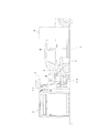
図1は、本発明の給油装置の一実施例を示すものであって、アイランド1には、送液手段、計量手段等給油動作を制御する給油ユニット2と、給油ノズル3や後述する給油口開閉具等のツールを取出し可能に収容するツールストッカ4、アーム5によりツールを把持して車輌6の給油口112に移動させるロボット7、及びこれら給油ユニット2、ロボット7を統括的に制御する制御ユニット8が配置されている。
【0007】
給油ノズル3は、給油ユニット2の送液手段とホース9、10に接続され、またホース9、10は、図2に示したようにツールストッカ4の天板11に収容された滑動機構12にジョイント13により接続された上で支持されている。ジョイント13は、図示しない付勢手段、この実施例では錘により常時取出し方向とは逆方向(図中、左方向)に付勢され、給油ノズル3の移動に追従できるように移動可能にツールストッカ4の天板11に支持されている。
【0008】
図3は、ツールストッカ4の一実施例を示すものであって、天板11、及び給油ノズル3とツールを収容するツール収納部14を上下関係となるように支柱15により支持して構成されている。ツール収納部14は、この実施例では中央側に3つの給油ノズルをそれぞれ収容する給油ノズル収容孔16、17、18と、両側に燃料注入口ドア開閉ツールを収容する燃料注入口ドア開閉ツール収納部19、及びタンクキャップ開閉ツール収納部20が配置されている。なお、図中符号21は滑動機構12と錘とを接続するワイヤを示す。
【0009】
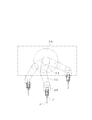
図4、及び図5は、ロボット7の一実施例を示すものであって、基台22に対して昇降及び回動可能に胴部23が嵌装し、胴部23の上端に3つのアーム24、25、26が水平に装着されている。アーム24は、胴部23に設けられた回動機構27に、またアーム25は、アーム24に装着された回動機構28により、さらにアーム26は、アーム25に装着された回動機構29にそれぞれ支持されていて、それぞれ独立に回動可能に構成されている。
先端アーム26の先端には、撮像手段30と、上述した各種ツールを把持するチャック機構31とが上下関係となるように回動機構32を介して垂直方向に回動可能に設けられている。さらにこの実施例では、測距動作に支障を来さない位置にレーザー測距装置などの測距手段100が設けられている。
【0010】
図6(イ)、(ロ)、(ハ)は、それぞれ燃料注入口ドア開閉ツールの一実施例を示すものであって、基台40は、その後端の下部にチャック機構31と係合する係合部40aが形成されており、上面に設けられた垂直回動軸41に吸着機構42が取付けられている。吸着機構42は、先端が開口したゴム等の弾性材料で構成された蛇腹43の後端を管体からなる軸44に取り付けて構成されている。軸44は、コイルバネ等の弾性体45により常時先端側に付勢され、ホース46を介して負圧の供給を受けている。
【0011】
吸着機構42は、回動基台47を介して垂直回動軸41に取付けられていて、回動基台47の後端に軸44に対して対称な斜面47a、47aが形成されている。この斜面47a、47aと当接するように2つのローラ48、48がエアシリンダ49により進退可能に配置されている。なお、図中符号50は、バキュームスイッチを、また51、52は、チャック機構側のプラグと係合してバキュームの供給を受けるコネクタを示す。
【0012】
図7(イ)、(ロ)、及び図8(イ)、(ロ)は、それぞれタンクキャップ開閉ツールの一実施例を示すものであって、燃料注入口ドア開閉ツールと同様に基台60は、その後端の下部にチャック機構31と係合する係合部60aが形成されており、上面に回動手段、この実施例ではエアモータ61が設けられている。エアモータ61の回転軸61aにはカップリング62を介してモータ61側が先細りに形成されたテーパ状の係合部63を備えた駆動軸64が接続されている。
【0013】
係合部63には軸方向に直交する軸65が設けられ、この軸65に長孔66を介して先端が2叉に形成されたグリップ67が、その後端を弾性部材、この実施例ではコイルバネ68により先端側(図では左側)に常時付勢された状態で取付けられている。これら軸65、長孔66、及びバネ68によりグリップ67が揺動可能な状態で回動することが可能となる。
【0014】
グリップ67の先端には開口69、69が設けられ、ホース70を介してバキュームが供給されている。なお、図中符号69は、バキュームスイッチを、また70、71は、チャック機構側のプラグと係合してバキュームの供給を受けるコネクタを、さらに72、73は、チャック機構側のプラグと係合してエアの供給を受けるコネクタを示す。
【0015】
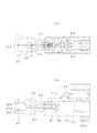
図9、図10、及び図11は、給油ノズルの一実施例を示すものであって、基台80は、その後端下部、及び後端上部にチャック機構31と係合する係合部80aが形成されており、上面に満タン検知機能を備えた給油ノズル81が取付けられている。この給油ノズル81は、特開平3-29796号公報等により周知の構造で、給油レバー82の引き上げにより開弁し、また後述する開口86aに液や泡が浸入したことにより作動する自動閉弁機構97により閉弁する主弁83を所要な部材として構成されている。自動閉弁機構97は、チャッキ弁84と、給油ノズル筒先部85の先端に開口86aを備えた流路86とにより構成されている。
【0016】
そして自動給油する関係上、レバー82の先端に対向する位置には、エアシリンダ87が配設されていて、エアの供給によりレバー82を引き上げ、引き上げとなった状態をスイッチ88により検出するように構成されている。なお、図中符号89は、筒先部の先端に設けられた開口89aに連通するベーパ吸引管を示す。
【0017】
胴部90と筒先部85の境界には、先端が開口する筒状の空間91が形成され、その先端にテーパ状のガイド部材92が、弾性部材、この実施例ではバネ93により筒先部85の側に常時付勢された状態で進退可能に取付けられている。また胴部90の先端には、ガイド部材92が胴部90の側に移動したことを検出する複数、この実施例では2つの当接センサーと、液の上昇を検出する液センサーとが設けられている。当接センサーは、この実施例ではガイド部材92に設けられた磁石93の磁束により開閉するリードスイッチ94とにより構成され、また液センサーは、下部に設けられたプリズム95により構成されている。
【0018】
そしてこの実施例においては、給油ノズルの挿入を容易にするため、筒先部85の先端には高分子等、金属よりも柔らかく、かつ成形性に富んだ材料、例えば高分子材料により中心部に通孔98aを備えた半球状の保護部材98が取付けられ、図10に示したように給油ノズル81は、その胴部90をチャック機構31に把持される基台80との間に弾性部材、この実施例ではゴム材96を介して取付けられている。
【0019】
これにより挿入過程で給油ノズル筒先部85の保護部材98が、その球面により給油口112をスムーズに通過し、また筒先部85が給入管114を移動する過程で筒先部85に外力が作用した場合にでも弾性部材96が弾性変形して追従移動可能ならしめる。
【0020】
図12は、同上装置の動作を統括する制御装置の一実施例を示すものであって、給油ユニット2の制御手段102は、油種判定手段103、計量機構制御手段104を備え、複数の挿入センサーを構成するスイッチ94、94からの信号をアンドゲートを介して、また複数のセンサー95、95からの信号をオアゲートを、さらに給油ノズルの引き上げを検出するスイッチ88からの信号を受け、給油レバー引き上げ用のエアシリンダ87を制御するように構成されている。
【0021】
また位置座標演算手段105は、撮像手段30、測距手段100からの信号を受け、演算結果をロボット制御手段107からアクセス可能に記憶手段106に格納する。なお、図中符号108は、給油口燃料注入口ドア開閉ツール、タンクキャップ開閉ツールのバキュームスイッチ59、69、及び給油ユニット2の制御手段102からの信号によりエアや負圧の供給するエア・負圧供給手段を示す。
【0022】
次にこのように構成した装置の動作について説明する。
給油を受ける車輌がアイランド1の所定位置に停止すると、ロボット7の先端アーム26が車輌の前後方向に移動して少なくも車輌6の2箇所の距離を測距手段100により測定し(図15 ステップ イ)、アイランド1に対する車輌6の傾きを判定して記憶手段106に格納する(図15 ステップ ロ)。
【0023】
ユーザは、車輌6の大まかな仕様、つまり、油種、給油口112の位置(左側、または右側)、燃料注入口ドア111の開閉方向(前方向、または後方向)、給入管114の延びている方向(左、右、下)等を制御ユニット8、また給油ユニット2のキーボードから入力する。なお、これらの情報を顧客に配布する給油カードに予め格納しておくことにより、カードリーダにより入力することも可能である。
【0024】
これらの情報を元にロボット7の先端アーム26に取付けられている撮像手段30により給油口112の燃料注入口ドア111を撮影する。位置座標演算手段105は、撮影された燃料注入口ドア111の複数の角部A、B、C、Dの座標データに基づいて、燃料注入口110の中心座標を算出して記憶手段106に格納する(図15 ステップ ハ)。
【0025】
ロボット7は、ストッカ4の燃料注入口ドア開閉ツールの収納部19に移動し(図15 ステップ ニ、ホ)、燃料注入口ドア開閉ツールにチャック機構31を装着する。これにより、ストッカ4の収納部19と燃料注入口ドア開閉ツールとのロックが解除されて取出しが可能となる(図15 ステップ ヘ)。ロボット7は、記憶手段106に格納されている座標データに基づいて先端の蛇腹43を燃料注入口ドア111に移動し、圧接する(図15 ステップ ト)。
【0026】
所定時間が経過すると(図15 ステップ チ)、エア・負圧供給手段108からバキュームが供給されて蛇腹43が燃料注入口ドア111を吸着する(図15 ステップ リ)。この吸着によりホース46の負圧が上昇するため、バキュームスイッチ50がオンとなり(図15 ステップ ヌ)、蛇腹43が確実に燃料注入口ドア111に吸着したことが検出され、エアシリンダ49にエアを供給して後退させてローラ48によるロックを解除する(図15 ステップ ル)。
【0027】
ロボット7は、入力されている燃料注入口ドア111の開閉方向のデータに基づいて、燃料注入口ドア111を開放する方向に燃料注入口ドア111を吸着した状態で所定距離だけ後退移動する(図15 ステップ オ)。この過程で蛇腹43は、垂直軸41を中心に水平方向に回動するとともに、バネ45に抗して軸方向に移動する。これにより、燃料注入口ドア111に無理な力を作用させることなく移動して、燃料注入口ドア111の係止を解いて車輌本体から引き離す。
【0028】
所定距離分だけ後退して燃料注入口ドア111が開放された時点で(図15 ステップ ワ)蛇腹43へのバキュームの供給を停止して(図15 ステップ カ)、ついで燃料注入口ドア111の表側に位置している蛇腹43を、燃料注入口ドア111の裏側に移動させ(図15 ステップ ヨ)、燃料注入口ドア111が開く方向に移動し(図15 ステップ タ)、所定距離、つまり燃料注入口ドア111を次の動作に支障を来さない程度まで移動した時点で(図15 ステップ レ)停止し、またエアシリンダ49を元の位置に復帰させて蛇腹43をアーム26の軸線方向に一致するように回動移動させる(図15 ステップ ソ)。
【0029】
ついで、ストッカ4から給油口112まで移動した軌跡データを基にストッカ4の収納部16に移動して(図15 ステップ ツ)燃料注入口ドア開閉ツールを所定位置に挿入する(図15 ステップ ネ)。燃料注入口ドア開閉ツールが所定位置まで挿入されると、収納部16と燃料注入口ドア開閉ツールとがロックされ、またチャック機構31との把持が解除される(図15 ステップ ナ)。
【0030】
燃料注入口ドア111の開放が確認された時点で(図16 ステップ イ)、ロボット7は記憶手段106に格納されている軌跡データに基づいて給油口112から所定の距離まで移動する(図16 ステップ ロ)。これにより撮像手段30により給油口112、及びタンクキャップ113が撮影可能となる。
【0031】
この場合、図14に示したように撮像手段30の光軸L1、L2とタンクキャップ113、または給油口112の形成面との間に傾きθが存在する場合には、タンクキャップ113、または給油口112が真円となる位置P2まで移動し、この位置の座標に基づいて給油口112の伸びる方向、つまり傾きθを算出して記憶手段106に記憶する(図16 ステップ ハ)。
【0032】
なお、周囲の照明や、給油口112の色に関係なく確実に検出するためには、図13に示したように車輌のボディ色に対してコントラストを有するリング部材115、給油口112の周囲に装着して、標識を付しておくのが望ましい。もとより、このようなマークはシールを貼着する等の方法で簡単に設けることができる。
このようなリング部材115に図13()に示したように複数、例えば少なくとも3つの規定位置にマーク115aを付しおき、撮像手段30からのデータによりリング部材115の中心を検出し、また測距手段100により各マーク115aの相対位置を検出することにより、リング部材115の傾き、つまり給油口の傾きを簡単に検出することができる。
【0033】
ロボット7は、ストッカ4のタンクキャップ開閉ツールの収納部20に移動し(図16 ステップ ニ、ホ)、タンクキャップ開閉ツールをチャック機構31に装着する。これにより、収納部20とタンクキャップ開閉ツールとのロックが解除されて取出しが可能となる(図16 ステップ ヘ)。ロボット7は、記憶手段106に格納されている座標データに基づいてタンクキャップ開閉ツールを車輌のタンクキャップ113に移動させる(図16 ステップ チ)。グリップ67がタンクキャップ113に弾接した時点で、エアモータ61にエア・負圧供給手段108からエアを供給してグリップ67を所定角度だけ正転させる(図16 ステップ リ)。これによりタンクキャップ113の把持部がグリップ67の叉67aに進入する。
【0034】
所定角度回転した時点で(図16 ステップ ヌ)、回転を停止し、ついで後退させてグリップ67のねじれを除去する(図17 ステップ ル)。所定位置に後退した時点で(図16 ステップ オ)、再びグリップ67を前進させ、エア・負圧供給手段108からバキュームを供給して開口69にタンクキャップ113を吸着させる(図16 ステップ ワ)。
【0035】
この吸着により開口69の負圧が上昇するため、バキュームスイッチ69がオンとなり、グリップ67が確実にタンクキャップ113を吸着したことが検出されるから、エアモータ61にエアを供給してタンクキャップ113が開放される方向にグリップ67を回動させ、同時にタンクキャップ113のネジピッチに合わせて後退してタンクキャップ113を車輌6から外す(図16 ステップ カ)。
【0036】
所定回転数だけ回転した段階で(図16 ステップ ヨ)、回転を停止してさらに後退する(図16 ステップ タ)。燃料注入口ドア111に接触しない位置まで後退した時点で(図16 ステップ レ)、ストッカ4から給油口112まで移動した軌跡データを基にストッカ4の収納部20に移動して(図16 ステップ ソ)タンクキャップ113を吸着、保持した状態でタンクキャップ開閉ツールを所定位置に挿入する(図16 ステップ ツ)。
【0037】
タンクキャップ開閉ツールが所定位置まで挿入されると、収納部20とタンクキャップ開閉ツールとがロックされ、またチャック機構31との把持が解除される(図16 ステップ ネ)。この状態では、タンクキャップ113は、収納部20に所定の位置に位置決めされ、かつグリップ67と所定の位置関係を保持した状態で保管される。
【0038】
タンクキャップ113の開放が確認されると(図17 ステップ イ)、ロボット7は、適合油種の給油ノズルが収納されているストッカ4の収納部、例えば収納部16に移動し、給油開始時に入力された油種に対応する給油ノズルに移動し(図17 ステップ ロ、ハ)、給油ノズルにチャック機構31を装着する。これにより、ストッカ4と給油ノズルとのロックが解除されて取出しが可能となる(図17 ステップ ニ)。
【0039】
ロボット7は、記憶手段106に格納されている給油口112の座標、給入管114の傾きデータに基づいて給油ノズルの筒先部85を給油口112に、検出された給油口112の伸びる方向に可及的に平行に装入する(図17 ステップホ)。この過程で、給油ノズル3に接続されたホース10は、給油ユニット2のホース9に接続するジョイント13が前進し、ホース10の上端がストッカ4の収納部から可及的に離れた位置に移動する(図2におけるホース10’の状態)。
【0040】
これにより、車輌の位置に関わり無くロボット7は、他のホース10に邪魔されることなく給油ノズルを自由に移動させることができる。なお、ホース10をスムーズに前進させるには、エアシリンダ115等の駆動手段を天板11に設け、ジョイント13を強制的に移動させるのが望ましい。
【0041】
給油口112への挿入が開始されると、給油ノズル筒先部85は、保護部材98の球面により給油口112を滑って給入管114に進入する。進入の過程で筒先部85が車輌の給入管114に接触して外力が作用すると、弾性部材96が弾性変形して給油口112や給入管114に倣うようにガイドされる。これにより、ロボット7に対して精密な動作を必要とすることなく、給油ノズルを確実に給油口112から給入管114に挿入することができる。
【0042】
さらに給油ノズルが移動してガイド部材92がバネ93の力に抗して後退し、2つの挿入センサーを構成するスイッチ94からそれぞれ信号が出力し、規定位置まで挿入されたことが検出される(図17 ステップ ヘ)。この信号を受けて制御ユニット8は給油ユニット2を作動させる。なお、挿入センサーを構成するスイッチ94の1つでも信号が出力しない場合には、先端アーム26を若干移動させて、給油ノズルを確実に給油口に挿入し直す。
【0043】
ついで、給油ノズル筒先部85の開口89aからベーパを吸引して油種判定手段103により油種を確認し(図17 ステップ ト)、一致が確認できない場合には警報を発する(図17 ステップ チ)。油種の一致が確認できた場合には給油ユニット2の給油ポンプを作動させ、またエア・負圧供給手段108からエアを供給してエアシリンダ87を作動させて主弁83を開放する(図18 ステップ イ)。
【0044】
給油が開始されると、給油量が設定された給油量に到達したか(図18 ステップ ロ)、または満タンまで給油が進んだか(図18 ステップ ハ)を常時監視しつつ、さらに挿入センサーを構成するスイッチ94からの信号をも監視する(図18 ステップ ニ)。給油量が設定量に到達した場合には、給油ポンプ及びエアシリンダ87を停止させて主弁83を閉弁して給油を終了する(図18
ステップ ホ)。
【0045】
また満タンが検出された場合には(図18 ステップ ハ)自動閉弁機構97が作動して主弁83が閉弁し、前述のステップ(ホ)の過程を経て給油動作を終了する。
【0046】
給油動作が終了すると、ストッカ4の収納部16から給油口112まで移動した軌跡データを基にストッカ4の収納部16に移動して(図18 ステップ ヘ)給油ノズル3を所定位置に挿入する(図18 ステップ ト)。また、ホース10は、ジョイント13に作用する錘の力とエアシリンダ115からの変位を受けて奥側に後退し、他の給油ノズル3やツールの取出しに障害とならない位置に戻される。給油ノズルが所定位置まで挿入されると、収納部16と給油ノズル3とがロックされ、またチャック機構31との把持が解除される(図18 ステップ チ)。
【0047】
一方、給油の途中で挿入センサーのスイッチ94の1からでも信号が途絶えると(図18 ステップ ニ)、給油ポンプ及びエアシリンダ87とを停止させて送液を強制的に停止し、同時に警報を発する(図18 ステップ リ)。これにより、給油ノズル3が給油口112からの抜け出すのを未然に検出することができる。
【0048】
また、自動閉弁機構97の不調や故障により燃料が、車輌の燃料タンクから溢れる寸前まで上昇すると、液センサー95の1つからでも液検出信号が出力された場合には、前述のステップ(リ)の過程を経て給油動作を停止する。
【0049】
給油動作が終了すると(図19 ステップ イ)、前述のタンクキャップ開閉動作と同様にロボット7は、ストッカ4のタンクキャップ開閉ツールの収納部20に移動し(図19 ステップ ロ、ハ)、タンクキャップ開閉ツールにチャック機構31を装着する。これにより、ストッカ4の収納部20とタンクキャップ開閉ツールとのロックが解除され(図19 ステップ ニ)、タンクキャップ113を開口69のバキュームにより保持した状態でグリップ67の取出しが可能となる。
【0050】
ロボット7は、記憶手段106に格納されている給油口112の座標データに基づいてタンクキャップ開閉ツールを移動させ(図19 ステップ ホ、ヘ)、グリップ67に保持されているタンクキャップ113を給油口112に弾接させ(図19 ステップ ト)、この状態でエアモータ61にエア・負圧供給手段108のエアを供給してタンクキャップ113をねじ込む方向にグリップ67を所定数回転させる(図19 ステップ チ)。所定回転数だけ回転してねじ込みが終了した時点で回転を停止し、バキュームの供給を停止し、グリップ67を後退させる(図19 ステップ リ)。
【0051】
グリップ67が燃料注入口ドア111に接触しない位置まで後退した時点で(図19 ステップ ヌ)、後退を停止してストッカ4から給油口112まで移動した軌跡データを基にストッカ4の収納部に移動して(図19 ステップ ル)タンクキャップ開閉ツールを所定位置に挿入する。タンクキャップ開閉ツールが所定位置まで挿入されると(図19 ステップ オ)、収納部20とタンクキャップ開閉ツールとがロックされ、またチャック機構31との把持が解除される(図19 ステップ ワ)。
【0052】
タンクキャップ113の取付けが終了した段階で(図20 ステップ イ)、ロボット7は、ストッカ4の燃料注入口ドア開閉ツールの収納部16に移動し(図20 ステップ ロ、ハ)、燃料注入口ドア開閉ツールにチャック機構31を装着し、ストッカ4と燃料注入口ドア開閉ツールとのロックが解除されて取出す(図20 ステップ ニ)。ロボット7は、記憶手段106に格納されている座標データに基づいて燃料注入口ドア111の表側に対向する位置に移動する(図20 ステップ ホ、ヘ)。
【0053】
そこから燃料注入口ドア111を閉める方向に水平に移動して蛇腹43により燃料注入口ドア111を押圧(図20 ステップ ト)。所定距離の移動後に停止して、今度は車両方向に前進する(図20 ステップ チ)。これにより大きく開いていた燃料注入口ドア111がある程度まで閉められ、最後に押し込まれて完全に閉じられ、同時に車輌にロックする(図20 ステップ リ)。
【0054】
所定距離だけ前進した時点で(図20 ステップ ヌ)、前進を停止し、ストッカ4から給油口112まで移動した軌跡データを基にストッカ4の収納部19に移動する(図20 ステップ ル)。燃料注入口ドア開閉ツールが所定位置に挿入されると(図20 ステップ オ)、収納部19と燃料注入口ドア開閉ツールとがロックされ、またチャック機構31との把持が解除される(図20 ステップ ワ)。
【0055】
なお、上述の実施例においては、ロボットに測距手段を設け、ロボットの移動により車輌の複数箇所までの距離を計測しているが、アイランド1に車輌の前後方向に距離をおいて複数の測距手段を配置しても同様の作用を奏することは明らかである。
【0056】
また上述の実施例においては、燃料注入口ドア開閉ツール、タンクキャップ開閉ツール、及び給油ノズルをそれぞれ別体として構成したが、エアモータ等の駆動手段により回動する基台に一体に設け、ロボット7のアーム上で、所要の作業に応じて切替るようにしてもよい。これによれば、ストッカと車輌との間の移動を可及的に少なくして作業の高速化を図ることができる。
【0057】
さらに、本発明においては、特別なアダプタが装着されていない車輌に対して燃料注入口ドア、及びタンクキャップを開閉し、給油口に給油ノズルを挿入して自動給油することを主眼とするが、ロボットによる給油に対応する特別のアダプタを装着した車輌に対しても簡単に対応できることは明らかである。つまり、燃料注入口ドアやタンクキャップを開閉動作をスキップして給油ノズルを給油口に挿入させれば、自動給油が可能となる。
【0058】
【発明の効果】
以上、説明したように本発明によれば、車輌の燃料注入口ドア、及び給油口の画像データを積極的に利用して位置や傾きを検出でき、特別なアダプタを車輌に必要とすることなく、各種ツールを制御して自動給油することができる。
【図面の簡単な説明】
【図1】本発明の自動給油装置の一実施例を示す図である。
【図2】ツールストッカの一実施例を示す断面図である。
【図3】ツールストッカの一実施例を示す正面図である。
【図4】ロボットの一実施例を示す図である。
【図5】ロボットの一実施例を示す上面図である。
【図6】図(イ)乃至(ハ)は、それぞれ燃料注入口ドア開閉ツールの一実施例を示す上面図、正面図、及び側面図である。
【図7】図(イ)(ロ)は、それぞれタンクキャップ開閉ツールの一実施例を示す上面図、及び正面図である。
【図8】図(イ)、(ロ)は、それぞれ同上タンクキャップ開閉ツールの一実施例を示す側面図である。
【図9】給油ノズルの一実施例を示す断面図である。
【図10】図(イ)、(ロ)は、それぞれ同上給油ノズルの筒先部と胴部との境界の構造を示す正面図と断面図である。
【図11】同上給油ノズルと基台との取付け構造の他の実施例を示す図である。
【図12】同上装置の制御手段を示すブロック図である。
【図13】燃料注入口ドアの中心を判定する工程を説明する図である。
【図14】図(イ)、(ロ)は、それぞれ給油口に対する撮像手段の角度と、撮影された給油口の形状との関係を示す図であり、また図(ハ)は、給油口の傾きを検出するのに適したリング部材の実施例を示す図である。
【図15】同上装置により燃料注入口ドアを開放する動作を示すフローチャートである。
【図16】同上装置によりタンクキャップを開放する動作を示すフローチャートである。
【図17】同上装置により給油ノズルを挿入する工程を示すフローチャートである。
【図18】挿入された給油ノズルによる給油動作、及び給油ノズルの収納動作を示すフローチャートである。
【図19】同上装置によりタンクキャップを取る付ける動作を示すフローチャートである。
【図20】同上装置により燃料注入口ドアを閉める動作を示すフローチャートである。
【符号の説明】
1 アイランド
2 給油ユニット
3 給油ノズル
4 ツールストッカ
5 アーム
6 車輌
7 ロボット
8 制御ユニット
9、10 ホース
30 撮像手段
31 チャック機構
43 蛇腹
49 エアシリンダ
50 バキュームスイッチ
61 エアモータ
67 グリップ
69 バキュームスイッチ
81 給油ノズル
82 給油レバー
83 主弁
84 チャッキ弁
85 給油ノズル筒先部
85 筒先部
87 エアシリンダ
88 スイッチ
93 磁石
94 リードスイッチ
97 自動閉弁機構
98 保護部材
100 測距手段
111 燃料注入口ドア
113 タンクキャップ
114 給入管
115 エアシリンダ[0001]
BACKGROUND OF THE INVENTION
The present invention relates to an apparatus for automatically refueling a vehicle such as an automobile.
[0002]
[Prior art]
In recent years, in order to save labor in refueling work, a so-called robot that attaches a refueling nozzle connected to an oil feed pump to a robot arm, detects the refueling port of an automobile fuel tank by a sensor, and automatically inserts the refueling nozzle into the refueling port A fueling device is about to be introduced.
In order to smoothly perform fueling by such a robot fueling device, it is necessary that the tip of the fueling nozzle can be reliably positioned and inserted into the insertion port of the automobile fuel tank.
[0003]
[Problems to be solved by the invention]
For this reason, for example, as shown in Japanese Patent Publication No. 10-503994, it has been proposed to attach an adapter to the insertion port of an existing automobile fuel tank, but not all vehicles have an adapter. In addition, there is a problem that a marker for guiding the fueling nozzle to a predetermined position is required, and vehicles that can be automatically fueled are limited.
The present invention has been made in view of such problems, and the object of the present invention is to automatically dispose the fuel inlet door and the tank cap without requiring special processing for existing vehicles. The present invention is to provide an automatic refueling device that can be opened and closed and refueled by inserting a refueling nozzle into a refueling port.
[0004]
[Means for Solving the Problems]
In order to solve such a problem, in the automatic fueling device of the present invention, a fuel inlet door, a tool for opening and closing a tank cap, a stocker containing a fueling nozzle, and between the stocker and a fuel inlet of a vehicle. An imaging means for photographing the fuel inlet port of the vehicle and the fuel filler port, Image data from the imaging means And a position coordinate calculation means for calculating the coordinate position of the fuel filler port and a means for controlling the robot based on the coordinate position.
[0005]
[Action]
The position and the inclination are detected by actively using the image data of the fuel inlet door and the fuel inlet of the vehicle, and the tool is controlled based on the detected data.
[0006]
DETAILED DESCRIPTION OF THE INVENTION
Therefore, details of the present invention will be described below based on the illustrated embodiment.
FIG. 1 shows an embodiment of an oil supply apparatus according to the present invention. An
[0007]
The
[0008]
FIG. 3 shows an embodiment of the
[0009]
FIGS. 4 and 5 show an embodiment of the
At the distal end of the
[0010]
6 (a), 6 (b), and 6 (c) each show an embodiment of a fuel inlet door opening / closing tool, and the
[0011]
The
[0012]
FIGS. 7 (a), (b), and FIGS. 8 (a), (b) show examples of tank cap opening / closing tools, respectively, and the
[0013]
The
[0014]
[0015]
9, 10, and 11 show an embodiment of the oiling nozzle. The
[0016]
For the purpose of automatic refueling, an
[0017]
A
[0018]
In this embodiment, in order to facilitate the insertion of the oiling nozzle, the tip of the
[0019]
As a result, when the
[0020]
FIG. 12 shows an embodiment of a control device that controls the operation of the apparatus. The control means 102 of the
[0021]
The position coordinate calculation means 105 receives signals from the imaging means 30 and the distance measurement means 100 and stores the calculation results in the storage means 106 so as to be accessible from the robot control means 107.
[0022]
Next, the operation of the apparatus configured as described above will be described.
When the vehicle to be refueled stops at a predetermined position on the
[0023]
The user can specify the rough specifications of the
[0024]
Based on these pieces of information, the imaging means 30 attached to the
[0025]
The
[0026]
When the predetermined time has passed (
[0027]
Based on the input data of the opening / closing direction of the fuel inlet door 111, the
[0028]
When the fuel inlet door 111 is retreated by a predetermined distance (
[0029]
Next, based on the trajectory data moved from the
[0030]
When the opening of the fuel inlet door 111 is confirmed (FIG. 16 step A), the
[0031]
In this case, as shown in FIG. 14, when there is an inclination θ between the optical axes L1 and L2 of the image pickup means 30 and the formation surface of the
[0032]
In order to reliably detect the surrounding illumination and the color of the fuel filler port 112, as shown in FIG. It is desirable to put on and attach a sign. Of course, such a mark can be easily provided by a method such as sticking a seal.
As shown in FIG. 13A, a plurality of, for example, at least three marks 115a are attached to such a
[0033]
The
[0034]
At the point of rotation by a predetermined angle (
[0035]
Since the negative pressure of the
[0036]
At the stage where it has rotated by a predetermined number of revolutions (
[0037]
When the tank cap opening / closing tool is inserted to a predetermined position, the
[0038]
When the opening of the
[0039]
The
[0040]
Thereby, the
[0041]
Refueling port When the insertion into 112 is started, the oil supply
[0042]
Further, the oil supply nozzle moves, the
[0043]
Next, the vapor is sucked from the
[0044]
When refueling is started, the insertion sensor is further monitored while constantly monitoring whether the refueling amount has reached the set refueling amount (
Step e).
[0045]
When full tank is detected (FIG. 18 Step C), the automatic
[0046]
When the refueling operation is completed, based on the trajectory data moved from the
[0047]
On the other hand, if the signal is interrupted even from one of the
[0048]
In addition, when the fuel rises to the point where it overflows from the fuel tank of the vehicle due to malfunction or failure of the automatic
[0049]
When the refueling operation is completed (FIG. 19 Step A), the
[0050]
The
[0051]
When the
[0052]
When the installation of the
[0053]
From there, the fuel inlet door 111 is moved horizontally in the closing direction, and the fuel inlet door 111 is pressed by the bellows 43 (step in FIG. 20). It stops after moving a predetermined distance, and this time advances in the direction of the vehicle (step H in FIG. 20). As a result, the fuel inlet door 111 that has been largely opened is closed to a certain extent, finally pushed in and completely closed, and simultaneously locked to the vehicle (
[0054]
When the vehicle has advanced by a predetermined distance (
[0055]
In the above-described embodiment, the robot is provided with distance measuring means, and the distance to a plurality of locations of the vehicle is measured by the movement of the robot. Obviously, the same effect can be obtained even if the distance means is provided.
[0056]
In the above-described embodiment, the fuel inlet door opening / closing tool, the tank cap opening / closing tool, and the fueling nozzle are configured separately, but are provided integrally on a base that is rotated by driving means such as an air motor. The arm may be switched according to the required work. According to this, the movement between the stocker and the vehicle can be reduced as much as possible, and the operation speed can be increased.
[0057]
Furthermore, in the present invention, the main purpose is to open and close the fuel inlet door and the tank cap for a vehicle not equipped with a special adapter, and to automatically supply fuel by inserting a fuel nozzle into the fuel inlet. Obviously, it is possible to easily cope with a vehicle equipped with a special adapter corresponding to refueling by a robot. In other words, automatic refueling can be performed by skipping the opening and closing operation of the fuel inlet door and the tank cap and inserting the fuel filler nozzle into the fuel filler opening.
[0058]
【The invention's effect】
As described above, according to the present invention, the position and inclination of the vehicle can be detected by positively using the image data of the fuel inlet port and the fuel filler port of the vehicle, without requiring a special adapter in the vehicle. It is possible to automatically refuel by controlling various tools.
[Brief description of the drawings]
FIG. 1 is a diagram showing an embodiment of an automatic fueling device of the present invention.
FIG. 2 is a cross-sectional view showing an embodiment of a tool stocker.
FIG. 3 is a front view showing an embodiment of a tool stocker.
FIG. 4 is a diagram illustrating an example of a robot.
FIG. 5 is a top view showing an embodiment of a robot.
FIGS. 6A to 6C are a top view, a front view, and a side view, respectively, showing an embodiment of a fuel inlet door opening / closing tool.
FIGS. 7A and 7B are a top view and a front view, respectively, showing an embodiment of a tank cap opening / closing tool.
FIGS. 8A and 8B are side views showing an embodiment of the tank cap opening and closing tool, respectively.
FIG. 9 is a cross-sectional view showing an embodiment of a fueling nozzle.
FIGS. 10A and 10B are a front view and a cross-sectional view, respectively, showing the structure of the boundary between the cylinder tip portion and the body portion of the oiling nozzle.
FIG. 11 is a view showing another embodiment of the mounting structure of the oiling nozzle and the base.
FIG. 12 is a block diagram showing control means of the apparatus.
FIG. 13 is a diagram illustrating a process of determining the center of the fuel inlet door.
FIGS. 14 (a) and 14 (b) are diagrams showing the relationship between the angle of the imaging means with respect to the filler port and the shape of the photographed filler port, respectively, and FIG. 14 (c) is a diagram of the filler port. It is a figure which shows the Example of the ring member suitable for detecting inclination.
FIG. 15 is a flowchart showing the operation of opening the fuel inlet door by the apparatus.
FIG. 16 is a flowchart showing the operation of opening the tank cap by the apparatus.
FIG. 17 is a flowchart showing a process of inserting a fueling nozzle by the apparatus.
FIG. 18 is a flowchart showing an oil supply operation by an inserted oil supply nozzle and a storage operation of the oil supply nozzle.
FIG. 19 is a flowchart showing an operation of attaching a tank cap by the apparatus.
FIG. 20 is a flowchart showing the operation of closing the fuel inlet door by the apparatus.
[Explanation of symbols]
1 island
2 Refueling unit
3 Refueling nozzle
4 Tool stocker
5 arm
6 vehicles
7 Robot
8 Control unit
9, 10 hose
30 Imaging means
31 Chuck mechanism
43 bellows
49 Air cylinder
50 vacuum switch
61 Air motor
67 grip
69 Vacuum switch
81 Refueling nozzle
82 Refueling lever
83 Main valve
84 Check valve
85 Refueling nozzle tube tip
85 Tube tip
87 Air cylinder
88 switches
93 Magnet
94 Reed switch
97 Automatic valve closing mechanism
98 Protection member
100 Ranging means
111 Fuel inlet door
113 Tank cap
114 Supply pipe
115 Air cylinder
Claims (7)
Priority Applications (1)
| Application Number | Priority Date | Filing Date | Title |
|---|---|---|---|
| JP2001047832A JP3738366B2 (en) | 2001-02-23 | 2001-02-23 | Automatic oiling device |
Applications Claiming Priority (1)
| Application Number | Priority Date | Filing Date | Title |
|---|---|---|---|
| JP2001047832A JP3738366B2 (en) | 2001-02-23 | 2001-02-23 | Automatic oiling device |
Publications (2)
| Publication Number | Publication Date |
|---|---|
| JP2002255291A JP2002255291A (en) | 2002-09-11 |
| JP3738366B2 true JP3738366B2 (en) | 2006-01-25 |
Family
ID=18909184
Family Applications (1)
| Application Number | Title | Priority Date | Filing Date |
|---|---|---|---|
| JP2001047832A Expired - Fee Related JP3738366B2 (en) | 2001-02-23 | 2001-02-23 | Automatic oiling device |
Country Status (1)
| Country | Link |
|---|---|
| JP (1) | JP3738366B2 (en) |
Families Citing this family (6)
| Publication number | Priority date | Publication date | Assignee | Title |
|---|---|---|---|---|
| FR2931451B1 (en) * | 2008-05-22 | 2010-12-17 | Fmc Technologies Sa | CONTROL DEVICE FOR SYSTEM FOR LOADING AND / OR UNLOADING FLUIDS |
| DE102016123188A1 (en) * | 2016-12-01 | 2018-06-07 | Dr. Ing. H.C. F. Porsche Aktiengesellschaft | Adjustable loading robot |
| CN108100981B (en) * | 2018-01-02 | 2023-06-20 | 北京汽车集团有限公司 | Vehicle, automatic oiling method and device |
| CN109767424B (en) * | 2018-12-13 | 2022-05-17 | 西安电子科技大学 | Binocular vision train water injection port detection and positioning method based on FPGA |
| CN114644315B (en) * | 2022-03-11 | 2023-06-06 | 江阴市富仁高科股份有限公司 | Device and method for accurately positioning fuel tank cover for automatic oiling |
| CN117268551A (en) * | 2023-11-21 | 2023-12-22 | 广州科易光电技术有限公司 | Method and device for detecting vehicles on oil distribution platform, equipment and storage medium |
-
2001
- 2001-02-23 JP JP2001047832A patent/JP3738366B2/en not_active Expired - Fee Related
Also Published As
| Publication number | Publication date |
|---|---|
| JP2002255291A (en) | 2002-09-11 |
Similar Documents
| Publication | Publication Date | Title |
|---|---|---|
| CN112299359B (en) | Full-automatic oiling robot with double-arm structure | |
| JP3738366B2 (en) | Automatic oiling device | |
| CN101209724B (en) | Handlebar locking device for motor bicycle | |
| JP2001517181A (en) | Automatic refueling system | |
| EP2053015B1 (en) | Refueling nozzle and automatic refueling system using the same | |
| EP3380355B1 (en) | Solenoid assembly for a valve | |
| CN114195083A (en) | Automatic robot refueling device and refueling method | |
| US20070137036A1 (en) | Apparatus and method for assembling vehicle wheel | |
| JP3748044B2 (en) | Lubrication nozzle for robot lubrication equipment | |
| JP3748043B2 (en) | Tool for automatic lubricator | |
| JP4283897B2 (en) | Positioning device for automatic refueling of vehicles | |
| JP3353966B2 (en) | Refueling robot device | |
| JP2008536758A (en) | Capless filler cover | |
| JPH05112396A (en) | Automatic oil feeder | |
| TWI821596B (en) | Gas container connecting apparatus | |
| KR100384504B1 (en) | Automatic oil supplying device | |
| JPH0643039Y2 (en) | Liquid injection gun | |
| CN216360397U (en) | Automatic terminal actuating mechanism and intelligent oiling robot refuel | |
| KR102439359B1 (en) | Automated gas supply system and method of removing endcap from gas container valve | |
| WO2024079495A1 (en) | Equipement kit, reception support, mounting device, methods for mounting and dismounting the adapter | |
| JP2793291B2 (en) | Refueling device | |
| KR20190030710A (en) | Electronic Evaporative Emission Management System | |
| JPH0738235Y2 (en) | Refueling device | |
| JP2008137463A (en) | Fuel feed system | |
| JP4260252B2 (en) | Lubrication device |
Legal Events
| Date | Code | Title | Description |
|---|---|---|---|
| A621 | Written request for application examination |
Free format text: JAPANESE INTERMEDIATE CODE: A621 Effective date: 20040114 |
|
| A977 | Report on retrieval |
Free format text: JAPANESE INTERMEDIATE CODE: A971007 Effective date: 20050624 |
|
| A131 | Notification of reasons for refusal |
Free format text: JAPANESE INTERMEDIATE CODE: A131 Effective date: 20050629 |
|
| A521 | Request for written amendment filed |
Free format text: JAPANESE INTERMEDIATE CODE: A523 Effective date: 20050822 |
|
| TRDD | Decision of grant or rejection written | ||
| A01 | Written decision to grant a patent or to grant a registration (utility model) |
Free format text: JAPANESE INTERMEDIATE CODE: A01 Effective date: 20051005 |
|
| A61 | First payment of annual fees (during grant procedure) |
Free format text: JAPANESE INTERMEDIATE CODE: A61 Effective date: 20051018 |
|
| R150 | Certificate of patent or registration of utility model |
Free format text: JAPANESE INTERMEDIATE CODE: R150 |
|
| FPAY | Renewal fee payment (event date is renewal date of database) |
Free format text: PAYMENT UNTIL: 20081111 Year of fee payment: 3 |
|
| FPAY | Renewal fee payment (event date is renewal date of database) |
Free format text: PAYMENT UNTIL: 20091111 Year of fee payment: 4 |
|
| LAPS | Cancellation because of no payment of annual fees |