JP3737101B1 - Exhaust gas purification device for internal combustion engine - Google Patents

Exhaust gas purification device for internal combustion engine Download PDF

Info

Publication number
JP3737101B1
JP3737101B1 JP2005187795A JP2005187795A JP3737101B1 JP 3737101 B1 JP3737101 B1 JP 3737101B1 JP 2005187795 A JP2005187795 A JP 2005187795A JP 2005187795 A JP2005187795 A JP 2005187795A JP 3737101 B1 JP3737101 B1 JP 3737101B1
Authority
JP
Japan
Prior art keywords
casing
metal strip
exhaust
exhaust gas
internal combustion
Prior art date
Legal status (The legal status is an assumption and is not a legal conclusion. Google has not performed a legal analysis and makes no representation as to the accuracy of the status listed.)
Expired - Fee Related
Application number
JP2005187795A
Other languages
Japanese (ja)
Other versions
JP2007009704A (en
Inventor
庄平 里永
Original Assignee
株式会社サンヨープロジェクト
Priority date (The priority date is an assumption and is not a legal conclusion. Google has not performed a legal analysis and makes no representation as to the accuracy of the date listed.)
Filing date
Publication date
Application filed by 株式会社サンヨープロジェクト filed Critical 株式会社サンヨープロジェクト
Priority to JP2005187795A priority Critical patent/JP3737101B1/en
Application granted granted Critical
Publication of JP3737101B1 publication Critical patent/JP3737101B1/en
Publication of JP2007009704A publication Critical patent/JP2007009704A/en
Expired - Fee Related legal-status Critical Current
Anticipated expiration legal-status Critical

Links

Images

Landscapes

  • Filtering Of Dispersed Particles In Gases (AREA)
  • Exhaust Gas Treatment By Means Of Catalyst (AREA)
  • Exhaust Silencers (AREA)
  • Processes For Solid Components From Exhaust (AREA)
  • Filtering Materials (AREA)

Abstract

【課題】構造が簡単で、内燃機関の排気管に対し簡単に取付け・取外しでき、洗浄も簡単に行え、黒煙や白煙の発生を極力無くすることができる排気ガス浄化装置を提供する。
【解決手段】円筒壁部1とこれの先端部を塞ぐ端壁部2とにより有底円筒状を形成され、円筒壁部1の軸方向中間部にガス抜き用開口部3が設けられ、端壁部2に排気孔4が設けられたケーシング5を備え、ケーシング5内の先端部側に金属細片6を密集装填し、金属細片装填部Mの手前側には内燃機関の排気管からケーシング5内に入った排気ガスの金属細片装填部Mへの流れ込みをガイドする排気流ガイド部材7を設け、ケーシング5の円筒壁部1の基端部1oを内燃機関の排気管の先端部に着脱自在に取り付けるようにした。
【選択図】図2
To provide an exhaust gas purification device that has a simple structure, can be easily attached to and detached from an exhaust pipe of an internal combustion engine, can be easily cleaned, and can eliminate generation of black smoke and white smoke as much as possible.
A cylindrical wall portion 1 and an end wall portion 2 that closes the distal end portion of the cylindrical wall portion 1 form a bottomed cylindrical shape, and a gas vent opening 3 is provided at an axially intermediate portion of the cylindrical wall portion 1 to end the end portion. A casing 5 having an exhaust hole 4 provided in the wall portion 2 is provided, and the metal strips 6 are densely loaded on the front end side in the casing 5, and an exhaust pipe of the internal combustion engine is provided on the front side of the metal strip loading portion M. An exhaust flow guide member 7 for guiding the flow of exhaust gas entering the casing 5 into the metal strip loading portion M is provided, and the base end portion 1o of the cylindrical wall portion 1 of the casing 5 is connected to the distal end portion of the exhaust pipe of the internal combustion engine. Removably attached to the.
[Selection] Figure 2

Description

本発明は、ディーゼルエンジン等の内燃機関の排気管から排出される排気ガスを浄化するための排気ガス浄化装置に関するもので、特に排気煙である黒鉛や白煙等をできるだけ無くするようにした排気ガス浄化装置に関する。   The present invention relates to an exhaust gas purification device for purifying exhaust gas discharged from an exhaust pipe of an internal combustion engine such as a diesel engine, and more particularly, exhaust gas in which graphite, white smoke, and the like, which are exhaust smoke, are eliminated as much as possible. The present invention relates to a gas purification device.

排気煙は臭いと共にディーゼルエンジン等内燃機関特有の問題であり、人体そのものへの直接的な害よりもむしろ交通視野の妨げや都市美観の悪化など視覚的な公害問題として取り上げられている。この排気煙には大きく分けて黒煙と白煙とがある。黒煙は、0.02〜0.04μ程度の微細炭素粒子がくっつき合った1〜30μのスス(煤)である。また、白煙は、冷時始動の場合の燃焼室の低温のために燃料が部分燃焼した液滴となって排出され、これが白色に見える場合の他、エンジンオイルが燃える時に生じることがある。その他に着火遅れによって生じる白煙も知られている。いずれにしても、黒煙や白煙は、人体に悪影響を及ぼすと共に環境を悪化するものであることから、このような黒鉛や白煙の発生を極力なくする必要がある。   Exhaust smoke is a problem peculiar to internal combustion engines such as diesel engines as well as odor, and is taken up as a visual pollution problem such as obstructing traffic vision and deteriorating urban beauty rather than direct harm to the human body itself. This exhaust smoke is roughly divided into black smoke and white smoke. The black smoke is 1-30 μ soot (soot) in which fine carbon particles of about 0.02-0.04 μ stick together. Further, white smoke is discharged as a partially burned droplet of fuel due to the low temperature of the combustion chamber at the time of cold start, and it may be generated when the engine oil burns in addition to the case where it looks white. In addition, white smoke caused by ignition delay is also known. In any case, black smoke and white smoke adversely affect the human body and deteriorate the environment. Therefore, it is necessary to minimize the generation of such graphite and white smoke.

然るに、従来より、ディーゼルエンジン等の内燃機関から排出される黒鉛等を除去するための装置が種々提案されているが、従来の排気ガス浄化装置は、ディーゼルエンジン等内燃機関の排気管への取付けが非常に面倒である上に、高価なフィルター等を使用したり構造が複雑であったりするために製作コストが高くつくなどの問題があった。   However, various devices for removing graphite and the like discharged from an internal combustion engine such as a diesel engine have been proposed, but the conventional exhaust gas purifying device is attached to an exhaust pipe of an internal combustion engine such as a diesel engine. However, there is a problem that the manufacturing cost is high because an expensive filter or the like is used or the structure is complicated.

本発明は、上記の課題に鑑み、構造が簡単にして、内燃機関の排気管に簡単に取付けできると共に、簡単に取外しできて、洗浄も簡単に行え、しかも黒煙や白煙をできるだけ発生させないようにすることができる排気ガス浄化装置を提供することを目的とする。   In view of the above problems, the present invention has a simple structure, can be easily attached to an exhaust pipe of an internal combustion engine, can be easily removed, can be easily cleaned, and does not generate black smoke or white smoke as much as possible. It is an object of the present invention to provide an exhaust gas purification device that can be configured as described above.

上記課題を解決するための手段を、後述する実施形態の参照符号を付して説明すると、請求項1に係る発明の内燃機関の排気ガス浄化装置は、円筒壁部1とこれの先端部を塞ぐ端壁部2とにより有底円筒状に形成され、円筒壁部1の軸方向中間部にガス抜き用開口部3が設けられ、端壁部2に複数の排気孔4が設けられたケーシング5を内燃機関の排気管の先端部に連成し、このケーシング5内の先端部側に任意形状の金属細片6を密集装填し、この金属細片装填部Mの手前側には内燃機関の排気管からケーシング5内に入った排気ガスの金属細片装填部Mへの流れ込みをガイドする排気流ガイド部材7を設け、該排気流ガイド部材7は、長尺状の金属帯板11を渦巻状に巻成したものからなることを特徴としている。 Means for solving the above problems will be described with reference numerals in the embodiments described later. The exhaust gas purifying apparatus for an internal combustion engine according to claim 1 includes a cylindrical wall portion 1 and a tip portion thereof. A casing having a bottomed cylindrical shape formed by an end wall portion 2 to be closed, a gas vent opening 3 provided in an axial intermediate portion of the cylindrical wall portion 1, and a plurality of exhaust holes 4 provided in the end wall portion 2. 5 is coupled to the front end portion of the exhaust pipe of the internal combustion engine, the metal strips 6 having an arbitrary shape are densely loaded on the front end side in the casing 5, and the internal combustion engine is disposed on the front side of the metal strip loading portion M. An exhaust flow guide member 7 for guiding the flow of exhaust gas entering the casing 5 from the exhaust pipe into the metal strip loading portion M is provided , and the exhaust flow guide member 7 is provided with a long metal strip 11. It is characterized by being made of a spiral wound .

請求項2に係る発明の内燃機関の排気ガス浄化装置は、円筒壁部1とこれの先端部を塞ぐ端壁部2とにより有底円筒状を形成され、円筒壁部1の軸方向中間部にガス抜き用開口部3が設けられ、端壁部2に複数の排気孔4が設けられたケーシング5を備え、このケーシング5内の先端部側に任意形状の金属細片6を密集装填し、この金属細片装填部Mの手前側には内燃機関の排気管からケーシング5内に入った排気ガスの金属細片装填部Mへの流れ込みをガイドする排気流ガイド部材7を設け、該排気流ガイド部材7は、長尺状の金属帯板11を渦巻状に巻成したものからなり、しかしてケーシング5の円筒壁部1の基端部1oを内燃機関の排気管の先端部に着脱自在に取り付けるようにしたことを特徴としている。 The exhaust gas purifying device for an internal combustion engine according to a second aspect of the present invention has a bottomed cylindrical shape formed by the cylindrical wall portion 1 and the end wall portion 2 that closes the tip end portion of the cylindrical wall portion 1. Is provided with a casing 5 provided with a venting opening 3 and a plurality of exhaust holes 4 in the end wall 2, and metal strips 6 having an arbitrary shape are densely loaded on the front end side of the casing 5. the forward side of the metal strip loading unit M is provided with an exhaust flow guide member 7 for guiding the flow of the metal strip loading unit M of the exhaust gas entering into the casing 5 from the exhaust pipe of an internal combustion engine, the exhaust The flow guide member 7 is formed by winding a long metal strip 11 in a spiral shape, and the base end 1o of the cylindrical wall 1 of the casing 5 is attached to and detached from the front end of the exhaust pipe of the internal combustion engine. The feature is that it can be installed freely.

請求項3は、請求項に記載の内燃機関の排気ガス浄化装置において、ケーシング5の円筒壁部1には、その基端から軸方向に沿ってガス抜き用開口部3に至る切れ目10を入れてなることを特徴とする。 According to a third aspect of the present invention, in the exhaust gas purifying device for an internal combustion engine according to the second aspect , the cylindrical wall 1 of the casing 5 has a cut 10 extending from the base end to the gas vent opening 3 along the axial direction. It is characterized by being put in.

請求項4に係る発明の内燃機関の排気ガス浄化装置は、円筒状本体16と、この円筒状本体16の先端部に着脱自在に取り付けられる有底円筒状の端部ケーシング17とからなり、円筒状本体16の所要部にガス抜き用開口部3が設けられ、端部ケーシング17の端壁部18に複数の排気孔4が設けられてなるケーシング5の円筒状本体16を内燃機関の排気管の先端部に連成し、このケーシング5の端部ケーシング17内に任意形状の金属細片6を密集装填すると共に、この金属細片装填部Mの手前側には内燃機関の排気管からケーシング5内に入った排気ガスの金属細片装填部Mへの流れ込みをガイドする排気流ガイド部材7を設け、該排気流ガイド部材7は、長尺状の金属帯板11を渦巻状に巻成したものからなることを特徴とする。 The exhaust gas purifying device for an internal combustion engine according to a fourth aspect of the present invention comprises a cylindrical main body 16 and a bottomed cylindrical end casing 17 that is detachably attached to the tip of the cylindrical main body 16. The cylindrical main body 16 of the casing 5, in which the gas vent opening 3 is provided in a required portion of the cylindrical body 16 and the plurality of exhaust holes 4 are provided in the end wall portion 18 of the end casing 17, is connected to the exhaust pipe of the internal combustion engine. The metal strips 6 having an arbitrary shape are densely loaded in the end casing 17 of the casing 5, and the metal strip loading portion M is connected to the casing from the exhaust pipe of the internal combustion engine. 5 is provided with an exhaust flow guide member 7 for guiding the flow of exhaust gas entering the metal strip loading portion M, and the exhaust flow guide member 7 winds a long metal strip 11 in a spiral shape. characterized in that it consists to ones.

請求項5に係る発明の内燃機関の排気ガス浄化装置は、円筒状本体16と、この円筒状本体16の先端部に着脱自在に取り付けられる有底円筒状の端部ケーシング17とからなり、円筒状本体16の所要部にガス抜き用開口部3が設けられ、端部ケーシング17の端壁部18に複数の排気孔4が設けられたケーシング5を備え、このケーシング5の端部ケーシング17内に任意形状の金属細片6を密集装填すると共に、この金属細片装填部Mの手前側には内燃機関の排気管からケーシング5内に入った排気ガスの金属細片装填部Mへの流れ込みをガイドする排気流ガイド部材7を設け、該排気流ガイド部材7は、長尺状の金属帯板11を渦巻状に巻成したものからなり、しかしてケーシング5の円筒状本体16の基端部を内燃機関の排気管の先端部に着脱自在に取り付けるようにしたことを特徴とする。 The exhaust gas purifying device for an internal combustion engine of the invention according to claim 5 comprises a cylindrical main body 16 and a bottomed cylindrical end casing 17 which is detachably attached to the distal end portion of the cylindrical main body 16. The casing 5 includes a casing 5 provided with a degassing opening 3 in a required portion and an end wall portion 18 of the end casing 17 provided with a plurality of exhaust holes 4. The metal strips 6 having an arbitrary shape are densely loaded on the front side, and the exhaust gas entering the casing 5 from the exhaust pipe of the internal combustion engine flows into the metal strip loading portion M on the front side of the metal strip loading portion M. The exhaust flow guide member 7 is provided by winding a long metal strip 11 in a spiral shape, and thus the base end of the cylindrical body 16 of the casing 5 is provided. Of the exhaust pipe of the internal combustion engine Characterized in that to attach detachably to the end.

請求項6は、請求項1〜5の何れかに記載の内燃機関の排気ガス浄化装置において、金属細片装填部M内に電気ヒーター14を挿入配置し、必要時に通電・加熱するようにしたことを特徴とする。   Claim 6 is the exhaust gas purifying device for an internal combustion engine according to any one of claims 1 to 5, wherein an electric heater 14 is inserted and disposed in the metal strip loading part M, and is energized and heated when necessary. It is characterized by that.

請求項7は、請求項5又は6に記載の内燃機関の排気ガス浄化装置において、ケーシング5の円筒状本体16には、その基端から軸方向に沿ってガス抜き用開口部3に至る切れ目10を入れてなることを特徴とする。   A seventh aspect of the present invention relates to the exhaust gas purifying apparatus for an internal combustion engine according to the fifth or sixth aspect, wherein the cylindrical main body 16 of the casing 5 has a cut extending from the base end to the gas vent opening 3 along the axial direction. 10 is included.

請求項8は、請求項1〜7の何れかに記載の内燃機関の排気ガス浄化装置において、前記金属細片装填部Mには金属細片6の他にセラミック片が装填されることを特徴とする。   An eighth aspect of the present invention is the exhaust gas purifying device for an internal combustion engine according to any one of the first to seventh aspects, wherein the metal strip loading portion M is loaded with a ceramic strip in addition to the metal strip 6. And

上記解決手段による発明の効果を、後述する実施形態の参照符号を付して説明すると、請求項1に係る発明の内燃機関の排気ガス浄化装置によれば、内燃機関の排気管からの排気ガスがケーシング5内の金属細片装填部Mを通過する際、排気ガス中の特に黒煙を形成する微細炭素粒子等が除去される。即ち、排気管からの排気ガスが金属細片装填部Mを通過する際に、排気ガス中の微細炭素粒子が金属細片6に付着して捕捉され、これによってケーシング5の端壁部2の排気孔4から排出される排気ガスはほとんど無色となる。またこの時、ケーシング5内に導入された排気ガスの一部がガス抜き用開口部3から排出されるため、ケーシング5内の通気性が維持されて、エンジンの機関性能、即ち馬力の低下が回避される。   The effect of the invention by the above solution will be described with reference numerals in the embodiments described later. According to the exhaust gas purification apparatus for an internal combustion engine of the first aspect, the exhaust gas from the exhaust pipe of the internal combustion engine When the gas passes through the metal strip loading part M in the casing 5, fine carbon particles that form particularly black smoke in the exhaust gas are removed. That is, when the exhaust gas from the exhaust pipe passes through the metal strip loading part M, the fine carbon particles in the exhaust gas adhere to and be captured by the metal strip 6, thereby the end wall 2 of the casing 5. The exhaust gas discharged from the exhaust hole 4 is almost colorless. At this time, since a part of the exhaust gas introduced into the casing 5 is discharged from the gas vent opening 3, the air permeability in the casing 5 is maintained, and the engine performance of the engine, that is, the horsepower is reduced. Avoided.

またトラックT等が例えば80〜100km/h程度の高速で走行している場合には、そのエンジンから排気ガス浄化装置Aのケーシング5内に導入される排気ガスの温度は、例えば700〜800℃程度と非常に高く、従ってケーシング5内の金属細片装填部Mをこの排気ガスの温度とほとんど同じ程度まで加熱されるから、排気ガスがこの金属細片装填部Mを通過する際には、排気ガス中の微細炭素粒子は、金属細片6に付着して捕捉されると共に、600〜800℃もの高温に加熱された金属細片6の高熱により燃焼されて消失され、金属細片6上にはほとんど滓が残らない。また、冷時始動の場合の燃焼室の低温のために燃料が部分燃焼した液滴となって排出される時、あるいは着火遅れや着火不良を生じた時のように燃料が不完全燃焼した場合には、そのような不完全燃焼ガスがケーシング5の金属細片装填部Mを通過することによって、その不完全燃焼ガスを完全燃焼させ、それにより白煙の発生をできるだけ無くすることができる。また、このように黒煙や白煙の発生を極力無くすると共に、排気ガス中の窒素酸化物も除去することもできる。   Further, when the truck T or the like is traveling at a high speed of, for example, about 80 to 100 km / h, the temperature of the exhaust gas introduced from the engine into the casing 5 of the exhaust gas purification apparatus A is, for example, 700 to 800 ° C. Since the metal strip loading part M in the casing 5 is heated to almost the same level as the temperature of the exhaust gas, when the exhaust gas passes through the metal strip loading part M, Fine carbon particles in the exhaust gas are attached to and captured by the metal strip 6 and are burned and lost by the high heat of the metal strip 6 heated to a high temperature of 600 to 800 ° C. Almost no habit remains. Also, when the fuel is discharged as partially burned droplets due to the low temperature of the combustion chamber at cold start, or when the fuel burns incompletely, such as when ignition delay or ignition failure occurs In such a case, the incomplete combustion gas passes through the metal strip loading part M of the casing 5 so that the incomplete combustion gas is completely combusted, thereby eliminating the generation of white smoke as much as possible. In addition, the generation of black smoke and white smoke is minimized as described above, and nitrogen oxides in the exhaust gas can be removed.

またこの排気ガス浄化装置によれば、金属細片装填部Mの手前側に、内燃機関の排気管からケーシング5内に入った排気ガスの金属細片装填部Mへの流れ込みをガイドする排気流ガイド部材7を設けているから、内燃機関の排気管からケーシング5内に入った排気ガスは、金属細片装填部Mにスムーズに流れ込み、一部の排気ガスが、ケーシング5内の通気性を維持する程度に排出されるようになり、これによって排気ガスの浄化作用をより有効に行なわせることができる。しかも、排気流ガイド部材7として、長尺状の金属帯板を渦巻状に巻成したものを採用するため、排気ガスの金属細片装填部Mへの流れ込みを有効に行なわせることができるFurther, according to this exhaust gas purifying apparatus, the exhaust flow that guides the flow of the exhaust gas that has entered the casing 5 from the exhaust pipe of the internal combustion engine into the metal strip loading portion M is on the front side of the metal strip loading portion M. Since the guide member 7 is provided, the exhaust gas that has entered the casing 5 from the exhaust pipe of the internal combustion engine flows smoothly into the metal strip loading portion M, and some of the exhaust gas has improved air permeability in the casing 5. As a result, the exhaust gas is exhausted to the extent that it is maintained, whereby the exhaust gas purification action can be performed more effectively. Moreover, as the exhaust flow guide member 7, to adopt that form winding an elongated metal strip spirally, it is possible to effectively perform the flow to the metal strip loading unit M of the exhaust gas .

また、この発明の排気ガス浄化装置によれば、円筒壁部1とこれの先端部を塞ぐ端壁部2とにより有底円筒状に形成され、円筒壁部1の軸方向中間部にガス抜き用開口部3が設けられ、端壁部2に複数の排気孔4が設けられたケーシング5を内燃機関の排気管の先端部に連成したものであるから、トラック等を製造する際に排気管の取付と同時に浄化装置を設置することができる。更にこの発明の排気ガス浄化装置は、構造がきわめて簡単で製作が容易であると共に、金属細片6として、工作機械による工作物の切削によって生じる切り屑をそのまま利用できるため、きわめて安価に提供できる。   Further, according to the exhaust gas purifying apparatus of the present invention, the cylindrical wall portion 1 and the end wall portion 2 that closes the tip end portion of the exhaust gas purifying device are formed in a bottomed cylindrical shape. Since the casing 5 provided with the opening 3 for use and the exhaust wall 4 provided in the end wall 2 is coupled to the tip of the exhaust pipe of the internal combustion engine, the exhaust gas is produced when manufacturing a truck or the like. A purification device can be installed simultaneously with the installation of the tube. Further, the exhaust gas purifying apparatus of the present invention is very simple in structure and easy to manufacture, and as the metal strip 6, chips generated by cutting a workpiece with a machine tool can be used as they are, so that it can be provided at a very low cost. .

請求項2に係る発明の排気ガス浄化装置によれば、ケーシング5の円筒壁部1の基端部1oを、内燃機関の排気管の先端部に嵌合して着脱自在に取り付けるようにしたもので、その取外し及び取付けが簡単容易であるから、頻繁に洗浄を行なうことができて、常に排気ガスの浄化作用を有効に行なわせることができる。他の効果については、上述した請求項1に係る発明の効果と同様である。   According to the exhaust gas purifying apparatus of the invention of claim 2, the base end portion 1o of the cylindrical wall portion 1 of the casing 5 is fitted to the distal end portion of the exhaust pipe of the internal combustion engine and is detachably attached. Since the removal and attachment are simple and easy, the cleaning can be performed frequently, and the exhaust gas purification action can always be effectively performed. Other effects are the same as those of the first aspect of the invention.

請求項3に係る発明によれば、ケーシング5の円筒壁部1には、その基端から軸方向に沿ってガス抜き用開口部3に至る切れ目10を入れているから、内燃機関の排気管の先端部9aに取り付ける際に、その先端部9aへの円筒壁部1の嵌め込みが容易となり、またその先端部9aに対し円筒壁部1の基端部側を適宜に拡縮変形させることによって、円筒壁部1の基端部を排気管部9aに密着させて確実強固に取り付けることができる。   According to the third aspect of the present invention, since the cylindrical wall portion 1 of the casing 5 is provided with the cut 10 extending from the base end to the gas vent opening portion 3 along the axial direction, the exhaust pipe of the internal combustion engine. When attaching to the distal end portion 9a, it is easy to fit the cylindrical wall portion 1 into the distal end portion 9a, and by appropriately expanding and contracting the proximal end portion side of the cylindrical wall portion 1 with respect to the distal end portion 9a, The base end portion of the cylindrical wall portion 1 can be securely attached by being brought into close contact with the exhaust pipe portion 9a.

請求項4に係る発明の排気ガス浄化装置は、円筒状本体16と、この円筒状本体16の先端部に着脱自在に取り付けられる有底円筒状の端部ケーシング17とからなり、円筒状本体16の所要部にガス抜き用開口部3が設けられ、端部ケーシング17の端壁部18に複数の排気孔4が設けられてなるケーシング5の円筒状本体16を内燃機関の排気管の先端部に連成したものであって、円筒状本体16側はトラック等を製造する際に排気管の取付と同時に浄化装置を設置することができ、しかして洗浄時には、端部ケーシング17のみを円筒状本体16から取り外して、この端部ケーシング17を洗浄液に漬けておけばよいから、洗浄が簡単容易となる。他の効果につては、上述した請求項1の発明による効果と同様である。   The exhaust gas purifying device of the invention according to claim 4 comprises a cylindrical main body 16 and a bottomed cylindrical end casing 17 that is detachably attached to the tip of the cylindrical main body 16. The cylindrical main body 16 of the casing 5 in which the gas vent opening 3 is provided in the required portion and the plurality of exhaust holes 4 are provided in the end wall portion 18 of the end casing 17 is used as the tip of the exhaust pipe of the internal combustion engine. In the cylindrical body 16 side, the purification device can be installed simultaneously with the attachment of the exhaust pipe when manufacturing a truck or the like. When cleaning, only the end casing 17 is cylindrical. Since it is only necessary to remove the end casing 17 from the main body 16 and immerse the end casing 17 in the cleaning liquid, the cleaning becomes easy and easy. Other effects are the same as those of the first aspect of the present invention.

請求項5に係る発明の排気ガス浄化装置は、ケーシング5の円筒状本体16の基端部を内燃機関の排気管の先端部に着脱自在に取り付けるようにしたものであるから、排気ガス浄化装置を、既設の排気管の先端部に簡単容易に取り付けて使用することができる。他の効果については、上述した請求項1に係る発明の効果と同様である。   The exhaust gas purification apparatus of the invention according to claim 5 is such that the base end portion of the cylindrical main body 16 of the casing 5 is detachably attached to the distal end portion of the exhaust pipe of the internal combustion engine. Can be easily attached to the tip of the existing exhaust pipe for use. Other effects are the same as those of the first aspect of the invention.

請求項6に係る発明によれば、例えばトラックT等が市街地を40〜50km/h程度で走行している場合にはエンジンから排気ガス浄化装置Aのケーシング5内に導入される排気ガスの温度が例えば300〜400℃程度と低く、金属細片装填部Mの金属細片6に付着した微細炭素粒子等を燃焼させることができないことから、この発明の排気ガス浄化装置のように、金属細片装填部M内に電気ヒーター14を挿入配置しておいて、必要時に通電・加熱することによって、金属細片装填部Mをその金属細片6に付着した微細炭素粒子等を燃焼させるに必要な温度、例えば600〜800℃程度まで加熱することができ、トラックT等が例えば80〜100km/h程度の高速で走行する場合と同様な効果を奏することができる。   According to the invention of claim 6, for example, when the truck T or the like is traveling in an urban area at about 40 to 50 km / h, the temperature of the exhaust gas introduced from the engine into the casing 5 of the exhaust gas purification device A. Is, for example, as low as about 300 to 400 ° C., and fine carbon particles and the like adhering to the metal strip 6 of the metal strip loading section M cannot be burned. Necessary for burning the fine carbon particles and the like adhering to the metal strip 6 by placing the electric heater 14 in the piece loading portion M and energizing and heating it when necessary. It can be heated to a high temperature, for example, about 600 to 800 ° C., and the same effect as when the truck T or the like travels at a high speed of about 80 to 100 km / h can be obtained.

請求項に係る発明によれば、ケーシング5の円筒状本体16には、その基端から軸方向に沿ってガス抜き用開口部3に至る切れ目10が入れてあるから、排気管の先端部9aに取り付ける際に、その先端部9aへの円筒状本体16の嵌め込みが容易となり、またその先端部9aに対し円筒状本体16の基端部側を適宜に拡縮変形させることにより、円筒状本体16の基端部を排気管部9aに密着させて確実強固に取り付けることができる。 According to the seventh aspect of the present invention, the cylindrical body 16 of the casing 5 is provided with the cut 10 extending from the base end to the gas vent opening 3 along the axial direction. When the cylindrical body 16 is attached to the distal end 9a, the cylindrical body 16 can be easily fitted into the distal end 9a, and the proximal end of the cylindrical body 16 is appropriately expanded and contracted with respect to the distal end 9a. The base end portion of 16 can be securely attached firmly to the exhaust pipe portion 9a.

請求項に係る発明によると、金属細片6の他にセラミック片を装填して金属細片装填部Mを形成することにより、高温排気ガスによる金属細片6及びセラミック片の加熱によって排気ガス中の微細炭素粒子をより有効に燃焼、除去することができる。 According to the eighth aspect of the present invention, the ceramic strip is loaded in addition to the metal strip 6 to form the metal strip loading portion M, whereby the exhaust gas is heated by heating the metal strip 6 and the ceramic strip by the high-temperature exhaust gas. The fine carbon particles therein can be burned and removed more effectively.

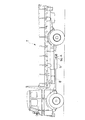
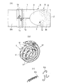
以下に本発明の好適な実施形態について図面を参照しながら説明すると、図1は本発明に係る排気ガス浄化装置Aをディーゼルエンジンを搭載したトラックTに実施した状態の側面図であり、図2の(a) は排気ガス浄化装置Aの拡大縦断面図、(b) は(a) のX−X線断面図、(c) は排気ガス浄化装置Aを前方から見た端面図である。   A preferred embodiment of the present invention will be described below with reference to the drawings. FIG. 1 is a side view showing a state in which an exhaust gas purifying apparatus A according to the present invention is implemented on a truck T equipped with a diesel engine. (A) is an enlarged longitudinal sectional view of the exhaust gas purification device A, (b) is a sectional view taken along the line XX of (a), and (c) is an end view of the exhaust gas purification device A as viewed from the front.

この排気ガス浄化装置Aは、円筒壁部1とこの円筒壁部1の先端部を塞ぐ端壁部2とによって有底円筒状に形成されていて、円筒壁部1の軸方向中間部にガス抜き用開口部3を設けると共に端壁部2に複数の排気孔4を設けたステンレス鋼製のケーシング5からなるもので、このケーシング5内にはその先端部側に任意形状の金属細片6を密集装填して、金属細片装填部Mを形成し、更にケーシング5内には金属細片装填部Mの後部側に排気流ガイド部材7を配置し、しかしてこのケーシング5の円筒壁部1の基端部1oをディーゼルエンジンの排気管8のマフラー9の先端側排気管部9aに嵌合して着脱自在に取り付けるようになっている。   The exhaust gas purifying apparatus A is formed in a bottomed cylindrical shape by a cylindrical wall portion 1 and an end wall portion 2 that closes the distal end portion of the cylindrical wall portion 1. The casing 5 is made of a stainless steel casing 5 provided with a plurality of exhaust holes 4 in the end wall portion 2, and in the casing 5, an arbitrarily shaped metal strip 6 on the tip side. Are densely loaded to form a metal strip loading portion M, and an exhaust flow guide member 7 is disposed in the casing 5 on the rear side of the metal strip loading portion M. The base end portion 1o of 1 is fitted to the distal end side exhaust pipe portion 9a of the muffler 9 of the exhaust pipe 8 of the diesel engine and is detachably attached.

ケーシング5の円筒壁部1は、その内径がマフラー9の先端側排気管部9aの外径より僅かに大きく形成されていると共に、図3の(a) に示すように、このケーシング5の円筒壁部1には、その基端から軸方向に沿ってガス抜き用開口部3に至る切れ目10が入れられている。   The cylindrical wall portion 1 of the casing 5 has an inner diameter that is slightly larger than the outer diameter of the exhaust pipe portion 9a on the tip end side of the muffler 9, and as shown in FIG. The wall 1 is provided with a cut 10 extending from the base end to the gas vent opening 3 along the axial direction.

ガス抜き用開口部3は、ケーシング5の排気口が端壁部2に設けた複数の排気孔4のみであれば、ケーシング5内の通気性が悪くなってエンジンの機関性能、即ち馬力が低下することから、これを回避するためのもので、図3の(a) に示すように、円筒壁部1の下側面部に略々半円形状に形成されている。   If the gas vent opening 3 has only a plurality of exhaust holes 4 provided in the end wall 2 as the exhaust port of the casing 5, the air permeability in the casing 5 deteriorates and the engine performance of the engine, that is, the horsepower decreases. Therefore, in order to avoid this, as shown in FIG. 3A, the cylindrical wall portion 1 is formed in a substantially semicircular shape on the lower side surface portion.

また、このガス抜き用開口部3の開口面積は、ケーシング5の円筒壁部1の断面積の2/4〜3/4が好ましいとされる。つまり、ガス抜き開口部3の開口面積が円筒壁部1の断面積の2/4以下にすれば、エンジンの機関性能が低下し、また開口面積が円筒壁部1の断面積の3/4以上にすると、最も肝心の排気ガス浄化性能が低下することになるからである。   The opening area of the gas vent opening 3 is preferably 2/4 to 3/4 of the cross-sectional area of the cylindrical wall 1 of the casing 5. That is, if the opening area of the gas vent opening 3 is 2/4 or less of the cross-sectional area of the cylindrical wall 1, the engine performance of the engine is reduced, and the opening area is 3/4 of the cross-sectional area of the cylindrical wall 1. This is because the most important exhaust gas purification performance will be lowered.

金属細片6としてはステンレス鋼の細片が好適である。ステンレス鋼は、常温ではもちろんのこと、高温においても酸化に強く、長く使用できるからである。またこの金属細片6は、特別に製造されるものではなく、ステンレス鋼材を旋盤等の工作機械によって切削加工する際に生ずる切り屑をそのまま使用する。具体的には、図3の(c) に示すように、長さが例えば50〜60mm程度のカール状のチップ片6aや任意の長さの螺旋状片6bなどを使用する。   The metal strip 6 is preferably a stainless steel strip. This is because stainless steel is resistant to oxidation at room temperature as well as at high temperatures and can be used for a long time. Further, the metal strip 6 is not specially manufactured, and chips generated when a stainless steel material is cut by a machine tool such as a lathe are used as they are. Specifically, as shown in FIG. 3C, a curled tip piece 6a having a length of, for example, about 50 to 60 mm, a spiral piece 6b having an arbitrary length, or the like is used.

排気流ガイド部材7は、マフラー9の先端側排気管部9aからケーシング5内に入った排気ガスが金属細片装填部Mにスムーズに流れ込むようにガイドするための部材で、例えば、図3の(b) に示すように、長尺状の金属帯板11を渦巻状に巻成して形成したものからなり、金属帯板11にはパンチ孔12が長手方向一定ピッチで穿設されている。この排気流ガイド部材7は、図2の(a) 及び(b) から分かるように、ケーシング5内においてガス抜き用開口部3よりも前方側で金属細片装填部Mの後部側に配備されている。   The exhaust flow guide member 7 is a member for guiding exhaust gas that has entered the casing 5 from the exhaust pipe portion 9a at the front end side of the muffler 9 so as to smoothly flow into the metal strip loading portion M. For example, FIG. As shown in (b), the metal strip 11 is formed by winding a long metal strip 11 in a spiral shape, and punch holes 12 are formed in the metal strip 11 at a constant pitch in the longitudinal direction. . As can be seen from FIGS. 2A and 2B, the exhaust flow guide member 7 is disposed in the casing 5 on the rear side of the metal strip loading portion M in front of the gas vent opening 3. ing.

ケーシング5をマフラー9の先端側排気管部9aに取り付けるには、ケーシング5の円筒壁部1の基端部1oをマフラー9の先端側排気管部9aに外嵌合して、適当なクランプ13で締め付け固定すればよい。この場合、円筒壁部1には、その基端から軸方向に沿ってガス抜き用開口部3に至る切れ目10が入れてあるから、排気管部9aに対して円筒壁部1の基端部側を適宜に拡縮変形させることにより、円筒壁部1の基端部内周面を排気管部9aの外周面に密着させて取り付けることができる。尚、クランプ13は、図示のような金属線条材によって形成されるものの他、金属製のベルトからなるものでもよく、いずれにしても簡単な操作で、ケーシング5の取付けを行なえるものを使用する。   In order to attach the casing 5 to the distal end side exhaust pipe portion 9 a of the muffler 9, the base end portion 1 o of the cylindrical wall portion 1 of the casing 5 is externally fitted to the distal end side exhaust pipe portion 9 a of the muffler 9 and an appropriate clamp 13 is attached. Tighten and fix with. In this case, the cylindrical wall portion 1 has a cut 10 extending from the proximal end thereof to the gas vent opening 3 along the axial direction, and therefore, the proximal end portion of the cylindrical wall portion 1 with respect to the exhaust pipe portion 9a. By appropriately expanding and contracting the side, the inner peripheral surface of the base end portion of the cylindrical wall portion 1 can be attached in close contact with the outer peripheral surface of the exhaust pipe portion 9a. In addition, the clamp 13 may be made of a metal belt as shown in the figure, or may be made of a metal belt. In any case, the clamp 13 can be attached to the casing 5 with a simple operation. To do.

次に、上記のようにしてトラックTのディーゼルエンジンの排気管8のマフラー9の先端側排気管部9aに取り付けた本発明の排気ガス浄化装置Aの作用について、以下に説明する。   Next, the operation of the exhaust gas purifying apparatus A of the present invention attached to the tip side exhaust pipe portion 9a of the muffler 9 of the exhaust pipe 8 of the diesel engine of the truck T as described above will be described below.

このディーゼルエンジンの運転によって、エンジンから排出された排気ガスは、図1に示す排気管8を通り、マフラー9を通過して先端側排気管部9aから排気ガス浄化装置Aのケーシング5内に導入されることになる。   By the operation of the diesel engine, the exhaust gas discharged from the engine passes through the exhaust pipe 8 shown in FIG. 1, passes through the muffler 9, and is introduced into the casing 5 of the exhaust gas purification device A from the distal end side exhaust pipe portion 9 a. Will be.

ケーシング5内に導入された排気ガスは、図の(a) に矢印Gにて示すように、そのほとんどがケーシング5内の先端部側にある金属細片装填部Mに入り、一部の排気ガスがガス抜き用開口部3より排出される。そして、排気ガスが金属細片装填部Mを通過する際に排気ガス中の特に黒煙を形成する微細炭素粒子が除去される。 Exhaust gas introduced into the casing 5, as shown by an arrow G in FIG. 2 (a), most of which go into the metal strip loading unit M in the front end portion of the casing 5, a part Exhaust gas is discharged from the opening 3 for degassing. Then, when the exhaust gas passes through the metal strip loading part M, fine carbon particles forming particularly black smoke in the exhaust gas are removed.

いま、トラックTが例えば40〜50km/hの比較的低速で走行している場合には、そのディーゼルエンジンから排気ガス浄化装置Aのケーシング5内に導入される排気ガスの温度は、例えば300〜400℃程度であり、従ってケーシング5内の金属細片装填部Mもこの排気ガスの温度とほとんど同じ程度まで加熱された状態となる。しかして、この排気ガスが金属細片装填部Mを通過する際に、排気ガス中の微細炭素粒子が金属細片6に付着して捕捉され、これによってケーシング5の端壁部2の排気孔4から排出される排気ガスはほとんど無色となる。   Now, when the truck T is traveling at a relatively low speed of, for example, 40 to 50 km / h, the temperature of the exhaust gas introduced from the diesel engine into the casing 5 of the exhaust gas purification apparatus A is, for example, 300 to Therefore, the metal strip loading part M in the casing 5 is also heated to almost the same temperature as the exhaust gas. Thus, when the exhaust gas passes through the metal strip loading portion M, fine carbon particles in the exhaust gas adhere to and be captured by the metal strip 6, thereby exhaust holes in the end wall portion 2 of the casing 5. The exhaust gas discharged from 4 is almost colorless.

またトラックTが高速道路等を80〜100km/hの高速で走行している場合には、そのディーゼルエンジンから排気ガス浄化装置Aのケーシング5内に導入される排気ガスの温度は、700〜800℃程度とかなり高く、従ってケーシング5内の金属細片装填部Mをこの排気ガスGの温度とほとんど同じ程度まで加熱されるから、排気ガスがこの金属細片装填部Mを通過する際には、排気ガス中の微細炭素粒子は、金属細片6に付着して捕捉されると共に、600〜800℃もの高温に加熱された金属細片6の高熱により燃焼されて消失され、金属細片6上に僅かに滓が残る状態となる。   When the truck T is traveling on a highway or the like at a high speed of 80 to 100 km / h, the temperature of exhaust gas introduced from the diesel engine into the casing 5 of the exhaust gas purification apparatus A is 700 to 800. Since the metal strip loading part M in the casing 5 is heated to almost the same temperature as the exhaust gas G, the exhaust gas passes through the metal strip loading part M. The fine carbon particles in the exhaust gas are attached to and trapped on the metal strip 6 and are burned and lost by the high heat of the metal strip 6 heated to a high temperature of 600 to 800 ° C. A slight wrinkle remains on the top.

この時、排気ガス中に含まれる水蒸気は、600〜800℃もの高温域を通過することによって過熱蒸気へと変化することになる。この過熱蒸気は、微細炭素粒子の酸化燃焼反応をさらに促進させる触媒しての効果があり、従って排気ガス中の窒素酸化物から酸素を遊離させて、微細炭素粒子に酸素を供給する作用がある。その結果、排気ガス中の微細炭素粒子及び窒素酸化物が効果的に除去され、ほとんど無色・無臭に近い状態で排気ガスを排出することができる。   At this time, the water vapor contained in the exhaust gas changes to superheated steam by passing through a high temperature range of 600 to 800 ° C. This superheated steam has an effect as a catalyst that further promotes the oxidative combustion reaction of fine carbon particles, and therefore has the effect of releasing oxygen from nitrogen oxides in the exhaust gas and supplying oxygen to the fine carbon particles. . As a result, fine carbon particles and nitrogen oxides in the exhaust gas are effectively removed, and the exhaust gas can be discharged in a state of almost colorless and odorless.

また、ディーゼルエンジンの冷時始動の場合の燃焼室の低温のために燃料が部分燃焼した液滴となって排出される時あるいは着火遅れや着火不良を生じた時のように燃料が不完全燃焼した場合には、そのような不完全燃焼ガスがケーシング5内の高温の金属細片装填部Mを通過することによって、その不完全燃焼ガスを完全燃焼させ、それにより白煙の発生を無くすることができる。   Also, when the diesel engine is cold start, the fuel is incompletely burned when the fuel is discharged as partially burned droplets due to the low temperature of the combustion chamber, or when ignition delay or ignition failure occurs. In such a case, the incomplete combustion gas passes through the hot metal strip loading portion M in the casing 5 to completely burn the incomplete combustion gas, thereby eliminating the generation of white smoke. be able to.

また、ケーシング5内に導入された排気ガスの一部がガス抜き用開口部3から排出されるため、ケーシング5内の通気性が維持されて、エンジンの機関性能、即ち馬力の低下が回避される。   Further, since a part of the exhaust gas introduced into the casing 5 is discharged from the gas vent opening 3, the air permeability in the casing 5 is maintained, and the engine performance of the engine, that is, the decrease in horsepower is avoided. The

そしてまた、ケーシング5内には、金属細片装填部Mの手前側に、パンチ孔12が帯板長手方向に一定ピッチで穿設された長尺状の金属帯板11を渦巻状に巻成してなる排気流ガイド部材7を設けているから、マフラー9の先端側排気管部9aからケーシング5内に入った排気ガスは、金属細片装填部Mにスムーズに流れ込み、一部の排気ガスが、ケーシング5内の通気性を維持する程度に排出されるようになり、これによって排気ガスの浄化作用をより有効に行なわせることができる。   In the casing 5, a long metal strip 11 having punch holes 12 formed at a constant pitch in the longitudinal direction of the strip is wound in a spiral shape on the front side of the metal strip loading portion M. Since the exhaust flow guide member 7 is provided, the exhaust gas that has entered the casing 5 from the exhaust pipe portion 9a at the front end of the muffler 9 smoothly flows into the metal strip loading portion M, and a part of the exhaust gas However, the exhaust gas is discharged to such an extent that the air permeability in the casing 5 is maintained, whereby the exhaust gas purification action can be performed more effectively.

即ち、この排気流ガイド部材7を設けていなければ、排気管部9aからケーシング5内に入った排気ガスが金属細片装填部Mの金属細片6に乱反射して、この乱反射した排気ガスにより、ケーシング5内の基端部から先端部へ向かう排気ガスの流れが攪乱され、ガス抜き用開口部3から排気ガスが流出し易くなるが、この排気流ガイド部材7を設けたことにより、ケーシング5内の基端部からの排気ガスは、金属帯板11を渦巻状に巻成して形成された排気流ガイド部材7を通ることによって金属細片装填部Mの金属細片6に乱反射することが少なく、そのまま金属細片装填部Mを通過するようになり、また乱反射した排気ガスは排気流ガイド部材7の金属帯板11の側面に当たったり、その帯板11のパンチ孔12を通り抜けることにより、乱反射によるガス流の乱れを消失させて、金属細片装填部Mを通過するようになる。その結果、ケーシング5内の基端部から先端部へ向かう排気ガスは、その流れを金属細片装填部Mの手前側で攪乱されることなく、そのままストレートに金属細片装填部Mに流れ込み、そしてガス抜き用開口部3からは、一部のわずかな排気ガスが、ケーシング5内の通気性を維持する程度に排出される。尚、この排気流ガイド部材7を形成する金属帯板11にはパンチ孔12を穿設しているが、このパンチ孔12は設けなくてもよい。   That is, if the exhaust flow guide member 7 is not provided, the exhaust gas that has entered the casing 5 from the exhaust pipe portion 9a is diffusely reflected on the metal strip 6 of the metal strip loading portion M, and the diffusely reflected exhaust gas The flow of the exhaust gas from the base end portion to the tip end portion in the casing 5 is disturbed and the exhaust gas easily flows out from the gas vent opening 3. By providing the exhaust flow guide member 7, the casing The exhaust gas from the base end portion in 5 is diffusely reflected on the metal strip 6 of the metal strip loading portion M by passing through the exhaust flow guide member 7 formed by winding the metal strip 11 in a spiral shape. The exhaust gas that has passed through the metal strip loading portion M as it is, and the diffusely reflected exhaust gas hits the side surface of the metal strip 11 of the exhaust flow guide member 7 or passes through the punch holes 12 of the strip 11. By And abolished the turbulence of the gas flow due to diffused reflection, made to pass through the metal strip loading unit M. As a result, the exhaust gas flowing from the base end portion to the tip end portion in the casing 5 flows straight into the metal strip loading portion M as it is without disturbing the flow on the front side of the metal strip loading portion M, A small amount of exhaust gas is discharged from the gas vent opening 3 to such an extent that the air permeability in the casing 5 is maintained. The metal strip 11 forming the exhaust flow guide member 7 is provided with a punch hole 12, but the punch hole 12 may not be provided.

また、この排気ガス浄化装置Aでは、ケーシング5の円筒壁部1の基端部1oを、マフラー9の先端側排気管部9aに嵌合して取外し自在に取り付けるようになっているから、ケーシング5を適宜に取り外し、このケーシング5とその内部にある金属細片装填部M及び排気流ガイド部材7に中性洗剤のスプレー液を吹き付けた後、水で洗い流すことによって、金属細片装填部Mの金属細片6及び排気流ガイド部材7に付着残存した微細炭素粒子等を簡単容易に洗浄除去でき、再び清浄な状態で使用することができる。   Further, in this exhaust gas purifying apparatus A, the base end portion 1o of the cylindrical wall portion 1 of the casing 5 is fitted into the distal end side exhaust pipe portion 9a of the muffler 9 so as to be detachably attached. 5 is removed as appropriate, and a spray solution of neutral detergent is sprayed on the casing 5 and the metal strip loading portion M and the exhaust flow guide member 7 in the casing 5, and then washed with water to wash the metal strip loading portion M. The fine carbon particles adhering and remaining on the metal strip 6 and the exhaust flow guide member 7 can be easily removed by washing, and can be used again in a clean state.

ケーシング5の取外しにあたってはクランプ13を緩めるだけでよく、その取外し及び取付け作業は極めて簡単容易であるから、頻繁に毎日でも洗浄を行なうことができ、従って常に排気ガスの浄化作用を有効に行なわせることができる。   When the casing 5 is removed, it is only necessary to loosen the clamp 13, and the removal and attachment work is very simple and easy. Therefore, the casing 5 can be frequently cleaned every day, so that the exhaust gas purification action is always effectively performed. be able to.

この排気ガス浄化装置Aによれば、ディーゼルエンジンから排出される黒煙の60〜70%を除去することができる。   According to this exhaust gas purification apparatus A, it is possible to remove 60 to 70% of the black smoke discharged from the diesel engine.

図4の(a) は本発明に係る他の排気ガス浄化装置Bを示したもので、この排気ガス浄化装置Bは、図2及び図3に示す排気ガス浄化装置Aとほとんど同じであるが、金属細片装填部内に電気ヒーターを挿入配置し、必要時に通電・加熱するようにしたケーシング5の金属細片装填部M内に電気ヒーター14を挿入配置した点が異なり、他の構成については排気ガス浄化装置Aと同様である。   FIG. 4 (a) shows another exhaust gas purification device B according to the present invention, which is almost the same as the exhaust gas purification device A shown in FIGS. The difference is that the electric heater 14 is inserted and arranged in the metal strip loading portion M of the casing 5 which is energized and heated when necessary, in the metal strip loading portion. This is the same as the exhaust gas purification device A.

即ち、前述のように、トラックT等が市街地を40〜50km/h程度で走行している場合にはエンジンから排気ガス浄化装置Aのケーシング5内に導入される排気ガスの温度が300〜400℃程度と低く、従って金属細片装填部Mの金属細片6に付着した微細炭素粒子等を燃焼させることができないことから、金属細片装填部M内に電気ヒーター14を挿入配置しておいて、必要時に通電・加熱することにより、金属細片装填部Mの温度を600〜800℃程度まで上昇させるようにしたものである。   That is, as described above, when the truck T or the like is traveling in an urban area at about 40 to 50 km / h, the temperature of the exhaust gas introduced from the engine into the casing 5 of the exhaust gas purification apparatus A is 300 to 400. Since the carbon particles and the like adhering to the metal strip 6 of the metal strip loading part M cannot be burned, the electric heater 14 is inserted and disposed in the metal strip loading part M. The temperature of the metal strip loading unit M is raised to about 600 to 800 ° C. by energizing and heating when necessary.

この電気ヒーター14は、例えば直径6mmのステンレス鋼線14aからなるもので、この鋼線14aを図示のようにケーシング5内に挿入できる程度の螺旋状に2〜3回巻成し、この鋼線14aの一端部をケーシング5の所要部に固着(アース接続)し、この鋼線14a他端部とケーシング5とをトラックTのバッテリ15に接続配線して、図4の(b)
に示すような電気回路を構成したもので、必要時にスイッチ16を閉成操作することによって、所要温度、例えば600〜800℃程度に加熱するようになっている。また、このステンレス鋼線14aに、金属細片6としての螺旋状片6b(図3の(c) 参照)を嵌装するようにすると共に、螺旋状片6b相互間にカール状のチップ片6a(図3の(c) 参照)を多数挿入すればよい。尚、ヒーター14の加熱時間は20秒程度でよい。
The electric heater 14 is made of, for example, a stainless steel wire 14a having a diameter of 6 mm. The steel wire 14a is wound two to three times in a spiral shape so as to be inserted into the casing 5 as shown in the figure. 4a is fixed to a required portion of the casing 5 (ground connection), and the other end of the steel wire 14a and the casing 5 are connected and connected to the battery 15 of the truck T.
The electrical circuit as shown in FIG. 1 is configured, and when necessary, the switch 16 is closed to heat it to a required temperature, for example, about 600 to 800 ° C. Further, a helical piece 6b (see FIG. 3 (c)) as a metal strip 6 is fitted to the stainless steel wire 14a, and a curled tip piece 6a is interposed between the helical pieces 6b. (See (c) of FIG. 3). The heating time of the heater 14 may be about 20 seconds.

この電気ヒーター14のスイッチ16は、例えば、トラックTの運転席にあるブレーキペダルに連動させておいて、走行中に運転手がブレーキをかけるためにブレーキペダルを踏んだ時に、スイッチ16が入ってヒーター14を例えば20秒間だけ加熱するように設定しておくと、非常に便利である。   The switch 16 of the electric heater 14 is linked to, for example, a brake pedal in the driver's seat of the truck T, and the switch 16 is turned on when the driver steps on the brake pedal to apply the brake while traveling. For example, it is very convenient to set the heater 14 so as to heat it for 20 seconds.

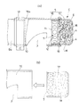
図5の(a) は更に他の排気ガス浄化装置Cを示したものである。この排気ガス浄化装置Cは、円筒状本体16と、この円筒状本体16の先端部に嵌合されて着脱自在に取り付けられる有底円筒状の端部ケーシング17とからなり、円筒状本体16の所要部にガス抜き用開口部3が設けられ、端部ケーシング17の端壁部18に複数の排気孔4が設けられたケーシング5を備え、このケーシング5の端部ケーシング17内に任意形状の金属細片6を密集装填して金属細片装填部Mを形成すると共に、この金属細片装填部Mの手前側に、図3の(b) に示すようにパンチ孔12が多数穿設された長尺状の金属帯板11を渦巻状に巻成してなる排気流ガイド部材7を配置し、このケーシング5の円筒状本体16の基端部16oを、図1に示すようなディーゼルエンジンの排気管8のマフラー9の先端側排気管部9aに嵌合して金属製ベルトからなるクランプ13により着脱自在に取り付けるようにしたものである。   FIG. 5A shows still another exhaust gas purification device C. FIG. The exhaust gas purification device C includes a cylindrical main body 16 and a bottomed cylindrical end casing 17 that is fitted to the tip of the cylindrical main body 16 and is detachably attached. A gas vent opening 3 is provided in a required portion, and a casing 5 having a plurality of exhaust holes 4 provided in an end wall portion 18 of the end casing 17 is provided. An arbitrary shape is provided in the end casing 17 of the casing 5. The metal strips 6 are densely loaded to form the metal strip loading portion M, and a number of punch holes 12 are formed on the front side of the metal strip loading portion M as shown in FIG. An exhaust flow guide member 7 formed by spirally winding an elongated metal strip 11 is disposed, and a base end portion 16o of a cylindrical main body 16 of the casing 5 is disposed on a diesel engine as shown in FIG. The exhaust pipe 8 has a muffler 9 with a front end side exhaust pipe portion 9a. The fitting is detachably attached by a clamp 13 made of a metal belt.

尚、この排気ガス浄化装置Cの端部ケーシング17に金属細片6を装填して形成される金属細片装填部Mの中に図4に示すような電気ヒーター14を挿入配置し、必要時に通電・加熱するようにしてもよい。   An electric heater 14 as shown in FIG. 4 is inserted and disposed in a metal strip loading portion M formed by loading the metal strip 6 into the end casing 17 of the exhaust gas purification device C, and when necessary. You may make it energize and heat.

またケーシング5の円筒状本体16には、その基端から軸方向に沿ってガス抜き用開口部3に至る切れ目10が入れてあるから、排気管の先端部9aに取り付ける際に、その先端部9aへの円筒状本体16の嵌め込みが容易となり、またその先端部9aに対し円筒状本体16の基端部側を適宜に拡縮変形させることによって、円筒状本体16の基端部内周面を排気管部9aの外周面に密着させて確実強固に取り付けることができる。   Further, the cylindrical body 16 of the casing 5 has a cut 10 extending from the base end to the gas vent opening 3 along the axial direction, so that the tip end portion of the casing 5 is attached to the tip end portion 9a of the exhaust pipe. It becomes easy to fit the cylindrical main body 16 into the 9a, and the base end side inner peripheral surface of the cylindrical main body 16 is exhausted by appropriately expanding and contracting the base end side of the cylindrical main body 16 with respect to the tip end portion 9a. The tube portion 9a can be securely attached to the outer peripheral surface of the tube portion 9a.

この排気ガス浄化装置Cでは、ケーシング5の端部ケーシング17内に金属細片装填部Mを形成すると共に、この金属細片装填部Mの手前側に排気流ガイド部材7を配備して、この端部ケーシング17の基端部側を円筒状本体16の先端部に例えばビス19により着脱自在に取り付けるようにしているから、洗浄時には、円筒状本体16はマフラー9の先端側排気管部9aから取り外す必要はなく、端部ケーシング17のみを円筒状本体16から取り外して、この端部ケーシング17を洗浄液に漬けておけばよいから、洗浄が簡単容易となり、毎日でも洗浄できて極めて便利である。図5の(b) は洗浄を終えた端部ケーシング17の基端部を円筒状本体16の先端部に嵌め込んで取り付けようとしている状態を示す。尚、端部ケーシング17を円筒状本体16に先端部に取り付け方法は、ビスに限らず、ねじによるねじ込み方式としてもよい。   In this exhaust gas purifying device C, a metal strip loading part M is formed in the end casing 17 of the casing 5, and an exhaust flow guide member 7 is provided on the front side of the metal strip loading part M. Since the base end side of the end casing 17 is detachably attached to the distal end portion of the cylindrical main body 16 with, for example, screws 19, the cylindrical main body 16 is removed from the exhaust pipe portion 9a on the distal end side of the muffler 9 during cleaning. There is no need to remove it, and only the end casing 17 is removed from the cylindrical main body 16 and the end casing 17 is immersed in the cleaning liquid. Therefore, cleaning is easy and easy, and it can be cleaned every day, which is very convenient. FIG. 5B shows a state where the base end portion of the end casing 17 that has been cleaned is fitted into the distal end portion of the cylindrical main body 16 to be attached. Note that the method of attaching the end casing 17 to the tip of the cylindrical body 16 is not limited to a screw, and may be a screwing method using screws.

以上説明した実施形態の図1〜図5に示される排気ガス浄化装置は何れも、ケーシング5を内燃機関の排気管の先端部に着脱自在に取り付けるようにしたものであるが、図にはケーシング5を内燃機関の排気管の先端部に連成した排気ガス浄化装置D,Eを示している。 Or any the exhaust gas purifying device shown in FIGS. 1-5 embodiment described, but the casing 5 is obtained to attach detachably to the distal end of the exhaust pipe of an internal combustion engine, FIG. 6 Exhaust gas purification apparatuses D and E are shown in which a casing 5 is coupled to the tip of an exhaust pipe of an internal combustion engine.

の(a) に示す排気ガス浄化装置Dは、円筒壁部1とこれの先端部を塞ぐ半球状の端壁部2とにより有底円筒状に形成され、円筒壁部1の軸方向中間部にガス抜き用開口部3が設けられ、端壁部2に複数の排気孔4が設けられてなるケーシング5を、マフラー9の先端側排気管部9aに一体又は一体的に形成したもので、浄化装置自体の構造は、図2〜図4に示す排気ガス浄化装置A,Bと同様であり、ケーシング5内の先端部側には任意形状の金属細片6が密集装填され、この金属細片装填部Mの手前側には内燃機関の排気管からケーシング5内に入った排気ガスの金属細片装填部Mへの流れ込みをガイドする排気流ガイド部材7が設けられており、また金属細片装填部M内に電気ヒーター14が挿入配備されている。この排気ガス浄化装置Dによれば、トラック等の製造時に浄化装置を設置することができる。 An exhaust gas purification device D shown in FIG. 6 (a) is formed in a bottomed cylindrical shape by a cylindrical wall portion 1 and a hemispherical end wall portion 2 that closes the tip of the cylindrical wall portion 1, and the axial direction of the cylindrical wall portion 1 A casing 5 in which a gas vent opening 3 is provided in an intermediate portion and a plurality of exhaust holes 4 are provided in an end wall portion 2 is formed integrally or integrally with a distal end side exhaust pipe portion 9a of a muffler 9. The structure of the purification device itself is the same as that of the exhaust gas purification devices A and B shown in FIGS. 2 to 4, and metal strips 6 having an arbitrary shape are densely loaded on the tip side in the casing 5. An exhaust flow guide member 7 for guiding the flow of exhaust gas entering the casing 5 from the exhaust pipe of the internal combustion engine into the metal strip loading portion M is provided on the front side of the metal strip loading portion M. An electric heater 14 is inserted and arranged in the metal strip loading unit M. According to the exhaust gas purification device D, the purification device can be installed at the time of manufacturing a truck or the like.

の(b) に示す排気ガス浄化装置Eは、円筒状本体16と、この円筒状本体16の先端部に着脱自在に取り付けられる有底円筒状の端部ケーシング17とからなり、円筒状本体16の所要部にガス抜き用開口部3が設けられ、端部ケーシング17の端壁部18に複数の排気孔が設けられてなるケーシング5の円筒状本体16を、排気管の先端部9aに一体に形成したもので、浄化装置自体の構造は、図5に示す排気ガス浄化装置Cと同様であり、ケーシング5の端部ケーシング17内に任意形状の金属細片6が密集装填されると共に、この金属細片装填部Mの手前側には内燃機関の排気管からケーシング5内に入った排気ガスの金属細片装填部Mへの流れ込みをガイドする排気流ガイド部材7が設けられている。また、この排気ガス浄化装置Eの端部ケーシング17に金属細片6を装填して形成される金属細片装填部Mの中に図4に示すような電気ヒーター14を挿入配備し、必要時に通電・加熱するようにしてもよい。 The exhaust gas purifying device E shown in FIG. 6 (b) includes a cylindrical main body 16 and a bottomed cylindrical end casing 17 that is detachably attached to the tip of the cylindrical main body 16, and has a cylindrical shape. The cylindrical main body 16 of the casing 5, in which the degassing opening 3 is provided in a required portion of the main body 16 and a plurality of exhaust holes are provided in the end wall portion 18 of the end casing 17, is connected to the distal end portion 9 a of the exhaust pipe. The structure of the purification device itself is the same as that of the exhaust gas purification device C shown in FIG. 5, and metal strips 6 of arbitrary shape are densely loaded in the end casing 17 of the casing 5. In addition, an exhaust flow guide member 7 for guiding the flow of exhaust gas entering the casing 5 from the exhaust pipe of the internal combustion engine into the metal strip loading portion M is provided on the front side of the metal strip loading portion M. Yes. Further, an electric heater 14 as shown in FIG. 4 is inserted and arranged in a metal strip loading portion M formed by loading the metal strip 6 into the end casing 17 of the exhaust gas purification device E, and when necessary, You may make it energize and heat.

この排気ガス浄化装置Eによれば、前記排気ガス浄化装置Dと同様にトラック等の製造時に浄化装置を設置することができると共に、洗浄時には、端部ケーシング17を円筒状本体16から取り外し、この端部ケーシング17を洗浄液に漬けるなどして洗浄すればよいから、洗浄が簡単で容易となる。   According to the exhaust gas purification device E, the purification device can be installed at the time of manufacturing a truck or the like as in the exhaust gas purification device D, and the end casing 17 is removed from the cylindrical body 16 at the time of cleaning. Since the end casing 17 may be cleaned by immersing it in a cleaning solution, the cleaning is simple and easy.

また、以上図1〜図によって説明した排気ガス浄化装置A〜Eでは、ケーシング5内の先端部側、あるいはケーシング5の端部ケーシング17内に任意形状の金属細片6を密集装填して金属細片装填部Mを形成しているが、金属細片装填部Mには金属細片6以外にセラミック片を装填することができる。即ち、金属細片6の他にセラミック片を装填して金属細片装填部Mを形成することにより、高温の排気ガスによる金属細片6及びセラミック片の加熱によって排気ガス中の微細炭素粒子をより有効に燃焼、除去することができる。 Further, in the exhaust gas purifying apparatuses A to E described above with reference to FIGS. 1 to 6 , the metal strips 6 having an arbitrary shape are densely loaded in the tip end side of the casing 5 or in the end casing 17 of the casing 5. Although the metal strip loading portion M is formed, the metal strip loading portion M can be loaded with ceramic pieces other than the metal strip 6. That is, by loading a ceramic piece in addition to the metal piece 6 to form the metal piece loading part M, the fine carbon particles in the exhaust gas are heated by heating the metal piece 6 and the ceramic piece by the high-temperature exhaust gas. It can be burned and removed more effectively.

図1は本発明に係る排気ガス浄化装置をディーゼルエンジンを搭載したトラックに実施した状態の側面図である。FIG. 1 is a side view of an exhaust gas purifying apparatus according to the present invention implemented on a truck equipped with a diesel engine. (a) は排気ガス浄化装置の拡大縦断面図であり、(b) は(a) のX−X線断面図、(c) は排気ガス浄化装置を前方から見た端面図である。(a) is an enlarged longitudinal sectional view of the exhaust gas purification device, (b) is a sectional view taken along line XX of (a), and (c) is an end view of the exhaust gas purification device as viewed from the front. (a) は図2の(a) に示す排気ガス浄化装置を下方より見た底面図、(b) は排気流ガイド部材を示す斜視図、収納部1は金属細片を示す斜視図である。2A is a bottom view of the exhaust gas purification device shown in FIG. 2A viewed from below, FIG. 2B is a perspective view showing an exhaust flow guide member, and the storage portion 1 is a perspective view showing a metal strip. . (a) は本発明に係る他の排気ガス浄化装置を示す縦断面図、(b) は電気ヒーターの電気回路図である。(a) is a longitudinal sectional view showing another exhaust gas purifying apparatus according to the present invention, and (b) is an electric circuit diagram of an electric heater. (a) は更に他の排気ガス浄化装置を示す一部縦断面図、(b) は端部ケーシングを円筒状本体に嵌め込んで取り付けようとしている状態の説明図である。(a) is a partial longitudinal sectional view showing still another exhaust gas purification device, and (b) is an explanatory view showing a state in which an end casing is fitted into a cylindrical main body to be attached. (a) ,(b) は本発明の更に他の排気ガス浄化装置を示す側面図である (a), (b) is a side view which shows the further another exhaust gas purification apparatus of this invention .

符号の説明Explanation of symbols

A〜E 排気ガス浄化装置
1 ケーシングの円筒壁部
1a 円筒壁部の基端部
2 ケーシングの端壁部
3 ガス抜き用開口部
4 排気孔
5 ケーシング
6 金属細片
7 排気流ガイド部材
M 金属細片装填部
10 切れ目
11 金属帯板
14 ヒーター
16 円筒状本体
17 端部ケーシング
A to E Exhaust gas purification apparatus 1 Cylindrical wall 1a of the casing Base end 2 of the cylindrical wall 2 End wall 3 of the casing 3 Gas vent opening 4 Exhaust hole 5 Casing 6 Metal strip 7 Exhaust flow guide member M Metal thin Piece loading portion 10 Cut 11 Metal strip 14 Heater 16 Cylindrical body 17 End casing

Claims (8)

円筒壁部とこれの先端部を塞ぐ端壁部とにより有底円筒状に形成され、円筒壁部の軸方向中間部にガス抜き用開口部が設けられ、端壁部に複数の排気孔が設けられたケーシングを内燃機関の排気管の先端部に連成し、このケーシング内の先端部側に任意形状の金属細片を密集装填し、この金属細片装填部の手前側には内燃機関の排気管からケーシング内に入った排気ガスの金属細片装填部への流れ込みをガイドする排気流ガイド部材を設け、該排気流ガイド部材は、長尺状の金属帯板を渦巻状に巻成したものからなる内燃機関の排気ガス浄化装置。 A cylindrical wall portion and an end wall portion that closes the tip of the cylindrical wall portion are formed into a bottomed cylindrical shape, a gas vent opening is provided at an axially intermediate portion of the cylindrical wall portion, and a plurality of exhaust holes are formed in the end wall portion. The provided casing is coupled to the tip of the exhaust pipe of the internal combustion engine, and metal strips having an arbitrary shape are densely loaded on the tip side in the casing, and the internal combustion engine is on the front side of the metal strip loading portion. An exhaust flow guide member for guiding the flow of exhaust gas entering the casing from the exhaust pipe into the metal strip loading portion is provided , and the exhaust flow guide member is formed by winding a long metal strip in a spiral shape. exhaust gas purification system of an internal combustion engine consisting of the thing. 円筒壁部とこれの先端部を塞ぐ端壁部とにより有底円筒状に形成され、円筒壁部の軸方向中間部にガス抜き用開口部が設けられ、端壁部に複数の排気孔が設けられたケーシングを備え、このケーシング内の先端部側に任意形状の金属細片を密集装填し、この金属細片装填部の手前側には内燃機関の排気管からケーシング内に入った排気ガスの金属細片装填部への流れ込みをガイドする排気流ガイド部材を設け、該排気流ガイド部材は、長尺状の金属帯板を渦巻状に巻成したものからなり、しかしてケーシングの円筒壁部の基端部を内燃機関の排気管の先端部に着脱自在に取り付けるようにした内燃機関の排気ガス浄化装置。 A cylindrical wall portion and an end wall portion that closes the tip of the cylindrical wall portion are formed into a bottomed cylindrical shape, a gas vent opening is provided at an axially intermediate portion of the cylindrical wall portion, and a plurality of exhaust holes are formed in the end wall portion. A metal strip having an arbitrary shape is densely loaded on the front end portion side of the casing, and the exhaust gas that has entered the casing from the exhaust pipe of the internal combustion engine is placed on the front side of the metal strip loading portion. An exhaust flow guide member for guiding the flow of metal into the metal strip loading portion is provided , and the exhaust flow guide member is formed by winding a long metal strip in a spiral shape, and thus the cylindrical wall of the casing An exhaust gas purifying device for an internal combustion engine in which a base end portion of the engine is detachably attached to a distal end portion of an exhaust pipe of the internal combustion engine. ケーシングの円筒壁部には、その基端から軸方向に沿ってガス抜き用開口部に至る切れ目を入れてなる請求項2に記載の内燃機関の排気ガス浄化装置。   The exhaust gas purifying device for an internal combustion engine according to claim 2, wherein a cut is formed in the cylindrical wall portion of the casing from the base end to the gas vent opening along the axial direction. 円筒状本体と、この円筒状本体の先端部に着脱自在に取り付けられる有底円筒状の端部ケーシングとからなり、円筒状本体の所要部にガス抜き用開口部が設けられ、端部ケーシングの端壁部に複数の排気孔が設けられてなるケーシングの円筒状本体を内燃機関の排気管の先端部に連成し、このケーシングの端部ケーシング内に任意形状の金属細片を密集装填すると共に、この金属細片装填部の手前側には内燃機関の排気管からケーシング内に入った排気ガスの金属細片装填部への流れ込みをガイドする排気流ガイド部材を設け、該排気流ガイド部材は、長尺状の金属帯板を渦巻状に巻成したものからなる内燃機関の排気ガス浄化装置。 A cylindrical main body and a bottomed cylindrical end casing that is detachably attached to the tip of the cylindrical main body, and a gas vent opening is provided in a required portion of the cylindrical main body. A cylindrical main body of a casing in which a plurality of exhaust holes are provided in an end wall portion is coupled to a distal end portion of an exhaust pipe of an internal combustion engine, and metal strips having an arbitrary shape are densely loaded in the end casing of the casing. In addition, an exhaust flow guide member for guiding the flow of exhaust gas entering the casing from the exhaust pipe of the internal combustion engine into the metal strip loading portion is provided on the front side of the metal strip loading portion, and the exhaust flow guide member Is an exhaust gas purifying device for an internal combustion engine comprising a long metal strip wound in a spiral shape . 円筒状本体と、この円筒状本体の先端部に着脱自在に取り付けられる有底円筒状の端部ケーシングとからなり、円筒状本体の所要部にガス抜き用開口部が設けられ、端部ケーシングの端壁部に複数の排気孔が設けられたケーシングを備え、このケーシングの端部ケーシング内に任意形状の金属細片を密集装填すると共に、この金属細片装填部の手前側には内燃機関の排気管からケーシング内に入った排気ガスの金属細片装填部への流れ込みをガイドする排気流ガイド部材を設け、該排気流ガイド部材は、長尺状の金属帯板を渦巻状に巻成したものからなり、しかしてケーシングの円筒状本体の基端部を内燃機関の排気管の先端部に着脱自在に取り付けるようにした内燃機関の排気ガス浄化装置。 A cylindrical main body and a bottomed cylindrical end casing that is detachably attached to the tip of the cylindrical main body, and a gas vent opening is provided in a required portion of the cylindrical main body. A casing having a plurality of exhaust holes in the end wall portion is provided, and metal strips having an arbitrary shape are densely loaded in the end casing of the casing, and an internal combustion engine is disposed on the front side of the metal strip loading portion. An exhaust flow guide member for guiding the flow of exhaust gas entering the casing from the exhaust pipe into the metal strip loading portion is provided , and the exhaust flow guide member is formed by winding a long metal strip in a spiral shape. made ones, Thus the exhaust gas purifying apparatus of an internal combustion engine to attach the base end portion of the cylindrical body of the casing detachably to the distal end of an exhaust pipe of an internal combustion engine. 金属細片装填部内に電気ヒーターを挿入配置し、必要時に通電・加熱するようにした請求項1〜5の何れかに記載の内燃機関の排気ガス浄化装置。   The exhaust gas purifying apparatus for an internal combustion engine according to any one of claims 1 to 5, wherein an electric heater is inserted and disposed in the metal strip loading section, and is energized and heated when necessary. ケーシングの円筒状本体には、その基端から軸方向に沿ってガス抜き用開口部に至る切れ目を入れてなる請求項5又は6に記載の内燃機関の排気ガス浄化装置。   The exhaust gas purification apparatus for an internal combustion engine according to claim 5 or 6, wherein the cylindrical main body of the casing is provided with a cut from the base end to the gas vent opening along the axial direction. 前記金属細片装填部には金属細片の他にセラミック片が装填される請求項1〜の何れかに記載の内燃機関の排気ガス浄化装置。 The exhaust gas purifying device for an internal combustion engine according to any one of claims 1 to 7 , wherein a ceramic piece is loaded in the metal strip loading section in addition to the metal strip.
JP2005187795A 2005-06-28 2005-06-28 Exhaust gas purification device for internal combustion engine Expired - Fee Related JP3737101B1 (en)

Priority Applications (1)

Application Number Priority Date Filing Date Title
JP2005187795A JP3737101B1 (en) 2005-06-28 2005-06-28 Exhaust gas purification device for internal combustion engine

Applications Claiming Priority (1)

Application Number Priority Date Filing Date Title
JP2005187795A JP3737101B1 (en) 2005-06-28 2005-06-28 Exhaust gas purification device for internal combustion engine

Publications (2)

Publication Number Publication Date
JP3737101B1 true JP3737101B1 (en) 2006-01-18
JP2007009704A JP2007009704A (en) 2007-01-18

Family

ID=35798440

Family Applications (1)

Application Number Title Priority Date Filing Date
JP2005187795A Expired - Fee Related JP3737101B1 (en) 2005-06-28 2005-06-28 Exhaust gas purification device for internal combustion engine

Country Status (1)

Country Link
JP (1) JP3737101B1 (en)

Cited By (1)

* Cited by examiner, † Cited by third party
Publication number Priority date Publication date Assignee Title
JP2009536290A (en) * 2006-05-03 2009-10-08 サバーテック リミテッド ライアビリティ カンパニー Emission reduction device and method

Families Citing this family (2)

* Cited by examiner, † Cited by third party
Publication number Priority date Publication date Assignee Title
CN1318949C (en) * 2000-11-06 2007-05-30 日本写真印刷株式会社 Touch panel capable of wide-area inputting
US8263202B2 (en) 2010-03-19 2012-09-11 Glenn Danny E Film based heating device and methods relating thereto

Cited By (1)

* Cited by examiner, † Cited by third party
Publication number Priority date Publication date Assignee Title
JP2009536290A (en) * 2006-05-03 2009-10-08 サバーテック リミテッド ライアビリティ カンパニー Emission reduction device and method

Also Published As

Publication number Publication date
JP2007009704A (en) 2007-01-18

Similar Documents

Publication Publication Date Title
JP5566134B2 (en) Exhaust gas temperature increase combustor
US5085049A (en) Diesel engine exhaust filtration system and method
JP2010169094A (en) Apparatus for cooling overheated gas in engine room
US5285640A (en) Integrated post-engine emissions heater, catalytic converter and muffler
US20060150617A1 (en) Exhaust system for an engine
JP3737101B1 (en) Exhaust gas purification device for internal combustion engine
JPH09317440A (en) Exhaust particulate purifier for internal combustion engine
ATE513120T1 (en) EXHAUST GAS CLEANING DEVICE FOR AN ENGINE
JP2008151093A (en) Exhaust device for four cycle engine
WO2000030734A1 (en) Method and apparatus for removing particulates
KR20080007660A (en) Exhaust-gas system for motor vehicle
SE501464C2 (en) Device for catalytic cleaning of exhaust gases from IC engine - comprises first catalyser placed downstream of engine, an HC trap, and second catalyser arranged in connection with HC trap
JP4500643B2 (en) Black smoke purification device for diesel engine
JP3121355U (en) Exhaust gas purification device for internal combustion engine
JP7207195B2 (en) Exhaust purification device for internal combustion engine
CN107869378A (en) The method of clean gas sensor
JP6658211B2 (en) Exhaust gas purification device
JP6811368B2 (en) Exhaust temperature raising device
US9732660B2 (en) Integrated sensor-catalyst
JP6642199B2 (en) Exhaust gas purification device
KR100494407B1 (en) Catalytic having a variable catalytic pellet and control mathod thereof
US10746066B2 (en) Controller and method of operating an exhaust-gas purification system
JP2019044660A (en) Exhaust gas post-processing method for diesel engine, and exhaust pipe
KR100199929B1 (en) Device and method for smoke removal
JP2001104735A (en) Exhaust gas cleaning apparatus and cleaning method

Legal Events

Date Code Title Description
TRDD Decision of grant or rejection written
A01 Written decision to grant a patent or to grant a registration (utility model)

Free format text: JAPANESE INTERMEDIATE CODE: A01

Effective date: 20051005

A61 First payment of annual fees (during grant procedure)

Free format text: JAPANESE INTERMEDIATE CODE: A61

Effective date: 20051025

R150 Certificate of patent or registration of utility model

Free format text: JAPANESE INTERMEDIATE CODE: R150

LAPS Cancellation because of no payment of annual fees