JP3736734B2 - Pointer-type instrument - Google Patents
Pointer-type instrument Download PDFInfo
- Publication number
- JP3736734B2 JP3736734B2 JP2000134174A JP2000134174A JP3736734B2 JP 3736734 B2 JP3736734 B2 JP 3736734B2 JP 2000134174 A JP2000134174 A JP 2000134174A JP 2000134174 A JP2000134174 A JP 2000134174A JP 3736734 B2 JP3736734 B2 JP 3736734B2
- Authority
- JP
- Japan
- Prior art keywords
- pointer
- light
- circuit board
- rotating shaft
- housing
- Prior art date
- Legal status (The legal status is an assumption and is not a legal conclusion. Google has not performed a legal analysis and makes no representation as to the accuracy of the status listed.)
- Expired - Fee Related
Links
Images


Description
【0001】
【発明の属する技術分野】
本発明は、例えば車両用計器等に用いられる指針式計器に関する。
【0002】
【従来の技術】
従来からこの種の指針式計器に使用される駆動装置として、例えば、ロータ磁石と、このロータ磁石を収納すると共にこのロータ磁石に固定された回転軸を前方側に突出するように軸支してなるハウジングと、このハウジングの外周に互いに交差するように巻装され通電によりロータ磁石に回転力を与える一対のコイルとを備えてなる可動磁石式計器が知られている。
【0003】
このように構成される駆動装置は、コイルに駆動信号を供給するための回路基板の前方側に機械的且つ電気的に固定され、また駆動装置の前方側には回転軸を貫通もしくは露出させる軸孔を有する文字板が配置され、この文字板の軸孔を通じて回転軸の先端に導光材からなる指針が装着される。指針が光供給を受けて発光する受光式の場合、駆動装置の側方エリアとなる回路基板領域に発光素子を装着し、この発光素子と指針の回転中心部との間に発光素子の照明光を指針に導く導光体を設け、この導光体により照明光を導いて指針を照明するようにしている。
【0004】
ところで、このように駆動装置を回路基板の前方側に配置した場合、駆動装置の配置領域には光源を配置することができず、回転軸付近に光源を配置して指針を照明することが不可能となるため、駆動装置を迂回して指針付近に延びる大型導光体の使用を余儀なくされるという事情がある。
【0005】
この点を考慮すると、例えば特開平11−14411号公報記載のごとく、駆動装置の前方側に回路基板を配置し、回転軸が回路基板を貫通するように構成するのが有利であり、このような構造を採用することで、駆動装置に対応する回路基板の前方側領域に発光素子配置スペースを確保でき、回転軸の近傍に配置した発光素子により指針の回転中心部に直接照明光を供給し指針を発光させることができる。
【0006】
【発明が解決しようとする課題】
しかしながら、指針の回転中心部直下に点光源からなる発光素子を配置した場合、指針の回転位置によって発光ムラが生じやすく、これに対処するため、回転軸を中心とした同心円上に多数の発光素子を配置する必要があるが、発光素子数の増加は、コスト上昇を招くだけでなく、指針照明に利用されない余分な照明光も増えるため、光漏れやハレーションを誘発しやすい。このため、例えば特開平8−122102号公報に記載されているように、発光素子と指針の回転中心部との間に導光体を介在させ、この導光体を通じて指針を照明することが考えられるが、当該公報記載の照明構造では、導光体が指針や回転軸からなる可動部品または指針を駆動する駆動装置とは別部品に装着されるため、部品の成形誤差や寸法誤差等によって指針の回転中心部と導光体との位置関係がばらつき、これが製品毎の照明ばらつきにつながるというデメリットがある。
【0007】
本発明はこの点に鑑みてなされたもので、その主な目的は、指針照明のばらつきを抑えることが可能な指針式計器を提供せんとするものである。
【0008】
【課題を解決するための手段】
本発明は、回転中心部より光供給を受けて発光する指針と、この指針を駆動する回転軸を前方側に突出してなる駆動装置と、この駆動装置の前方側に配置され前記回転軸を前方側に貫通する回路基板と、この回路基板の前方側に配置され前記指針に照明光を供給する発光素子とを備え、前記駆動装置にはロータ磁石を収納すると共に前記回転軸を軸支するハウジングが設けられ、このハウジングに前記回転軸に沿い前記回路基板を貫通して延びる筒状部が設けられ、この筒状部に前記発光素子からの照明光を前記指針に導く導光部材を設けたことを特徴とする。
【0009】
また本発明は、前記導光部材が前記回転軸を取り巻く筒状に形成されることを特徴とする。
【0010】
また本発明は、回転中心部より光供給を受けて発光する指針と、この指針を駆動する回転軸を前方側に突出してなる駆動装置と、この駆動装置の前方側に配置され前記回転軸を前方側に貫通する回路基板と、この回路基板の前方側に配置され前記指針に照明光を供給する発光素子とを備え、前記駆動装置にはロータ磁石を収納すると共に前記回転軸を軸支するハウジングが設けられ、このハウジングに前記回転軸に沿い前記回路基板を貫通して延びる筒状部が設けられ、この筒状部を導光性材料から形成すると共に前記発光素子からの照明光を前記指針に導く導光部を設けたことを特徴とする。
【0011】
また本発明は、前記ハウジングが前記回転軸を支持する一対のハウジングからなり、これらハウジングのうち少なくとも前記筒状部を有するハウジングを導光性材料から形成したことを特徴とする。
【0012】
【発明の実施の形態】
本発明による指針式計器は、回転中心部より光供給を受けて発光する受光式の指針と、この指針を駆動する回転軸を前方側に突出してなる例えば可動磁石式計器からなる駆動装置と、この駆動装置の前方側に配置され回転軸を前方側に貫通する回路基板と、この回路基板の前方側に配置され指針の回転中心部に照明光を供給する発光素子とを備える。駆動装置には回転軸と共に回路基板を貫通して前方側に延び回転軸を支持する筒状部が設けられ、この筒状部に発光素子からの照明光を指針に導く導光部材、例えばポリカーボネート樹脂、アクリル樹脂(PMMA)からなる透光性合成樹脂部材を設けたもので、導光部材は駆動装置の筒状部に保持される。このように駆動装置の筒状部に導光部材を設けたことにより、文字板や回路基板、その他の支持部品に導光部材を保持させた場合と比較して、部品の成形誤差や寸法誤差等による指針の回転中心部と導光部材との位置ばらつきを小さくすることができ、これにより製品毎の照明ばらつきを抑制することができる。筒状部に対する導光部材の取り付けは、圧入、嵌着、螺着、接着等、あらゆる取付手段を選択することができる。
【0013】
また導光部材の形状は、発光素子の位置や指針(回転中心部)の形状、発光素子と回転中心部との距離等に応じて適宜設定が可能であるが、特にその形状を回転軸を取り巻く筒状に形成すると、照明の均一性を得やすく有利である。
【0014】
また本発明による指針式計器は、回転中心部より光供給を受けて発光する受光式の指針と、この指針を駆動する回転軸を前方側に突出してなる例えば可動磁石式計器からなる駆動装置と、この駆動装置の前方側に配置され回転軸を前方側に貫通する回路基板と、この回路基板の前方側に配置され指針の回転中心部に照明光を供給する発光素子とを備える。駆動装置は回転軸と共に回路基板を貫通して前方側に延び回転軸を支持する筒状部を有し、この筒状部を導光性材料から形成すると共に発光素子からの照明光を指針に導く導光部を設けたものである。このように筒状部を導光性材料から形成して導光部を設けたことにより、駆動装置の一部に導光機能を持たせることができ、文字板や回路基板、その他の支持部品に導光部材を保持させた場合と比較して、部品の成形誤差や寸法誤差等による指針の回転中心部と導光部材との位置ばらつきを小さくすることができ、これにより製品毎の照明ばらつきを抑制することができる。
【0015】
筒状部を導光性となす手段としては、駆動装置が遮光性合成樹脂からなるハウジングを有し、このハウジングに筒状部が形成される場合、筒状部またはその周辺エリアに相当する箇所を透光性合成樹脂にて2色成形してもよいし、またハウジングが2つまたはそれ以上に分割形成される場合、少なくとも筒状部を含むハウジング構成部品を透光性合成樹脂にて形成してもよく、駆動装置の一部にて照明光が導光できるように構成されていればよい。
【0016】
【実施例】
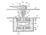
添付図面は何れも本発明の実施例を示すもので、以下、これらに基づいて本発明の実施例を説明する。図1は本発明の第1実施例による指針式計器の要部断面図、図2は導光部材を示す斜視図である。
【0017】
図1において、本実施例による指針式計器は、指針1と、この指針1の背後に配置される文字板2と、この文字板2上の指針1を計測量に基づいて駆動する駆動装置3と、この駆動装置3の前方側に配置される回路基板4と、この回路基板4の前方側に配置される発光素子5と、この発光素子5と指針1との間に配置される導光部材6とを備えている。
【0018】
指針1は、ポリカーボネートやアクリル樹脂等の透光性合成樹脂からなる指針本体11と、この指針本体11の回転中心部12を覆うカバー13とからなり、回転中心部12には照明光を導入する受光部14と、この受光部14から導入した照明光を先端側に反射する反射部15とが形成され、回転中心部12への照明光供給により線状に光輝するようになっている。
【0019】
文字板2は、透明材からなる基材に各種印刷を施して指針1に対応する目盛、文字、マーク(図示しない)を形成してなり、指針1の回動中心部12に対応した位置に開口部21を備えている。
【0020】
駆動装置3は、回転軸31を有する永久磁石からなるロータ磁石32と、このロータ磁石32を収納すると共に回転軸31を軸支する2分割形成された第1,第2のハウジング33,34と、このハウジング33,34の外側に交差して巻かれた一対のコイル35,36と、カップ型の金属製ケース37とから構成される交差コイル型可動磁石式計器からなり、回転軸31の先端に指針1が装着されている。そしてコイル35,36への電流供給により発生する合成磁界によりロータ磁石32を回転させ、これにより文字板2上の指針1を回転動作させるようになっている。
【0021】
第1,第2のハウジング33,34は遮光性の合成樹脂からなり、これらのうち回転軸31が突出する側となる第1のハウジング33には、回転軸31に沿って指針1側に延長し内部で回転軸31を支持する突出部(筒状部)38が形成されている。
【0022】
回路基板4は、駆動装置3や発光素子5を駆動制御する制御手段を搭載し、駆動装置3の前方側に配置され、回転軸31対応位置に設けられた貫通孔41を通じて突出部38が貫通するようになっている。
【0023】
発光素子5は、貫通孔41の周縁に位置して回路基板4の前方側に導通固定され、この場合、回転軸31を中心とした同心円上に適宜数(例えば4つ)配置されており、後に詳述する導光部材6を通じて指針1(指針本体11)を照明する。
【0024】
導光部材6は、指針本体11と同様、ポリカーボネート樹脂やアクリル樹脂等の透光性合成樹脂からなり、回転軸31を取り巻く円筒状に形成され、筒状部38の先端側に圧入固定されている。なお筒状部38には導光部材6の位置を規制する段部が形成されている。
【0025】
そして発光素子5側となる端部全周には、傾斜面からなる受光面61が形成され、この受光面61にて受光した発光素子5の照明光を受光部61とは反対側となる端面までガイドし、文字板2の開口部21を通じて指針1(指針本体11)の受光部14に供給できるようになっている。
【0026】
従って、発光素子5が発光すると、その照明光は導光部材6を通じて指針1の受光部14に供給され、指針1が発光する。
【0027】
以上のように本実施例では、回転中心部12より光供給を受けて発光する受光式の指針1と、この指針1を駆動する回転軸31を前方側に突出してなる例えば可動磁石式計器からなる駆動装置3と、この駆動装置3の前方側に配置され回転軸31を前方側に貫通する回路基板4と、この回路基板4の前方側に配置され指針1の回転中心部12に照明光を供給する発光素子5とを備え、駆動装置3には回転軸31と共に回路基板4を貫通して前方側に延び回転軸31を支持する筒状部38が設けられ、この筒状部38に発光素子5からの照明光を指針1の回転中心部12に導く導光部材6を設けたことにより、文字板や回路基板、その他の支持部品に導光部材を保持させた場合と比較して、部品の成形誤差や寸法誤差等に起因する指針1の回転中心部12と導光部材6との位置ばらつきを小さくでき、これにより製品毎の照明ばらつきを抑制することができる。
【0028】
また本実施例では導光部材6を回転軸31を取り巻く筒状に形成したことにより、指針1の回動位置に応じた照明ばらつきが抑えられ、照明の均一化に有利である。また本実施例では導光部材6に傾斜面からなる受光面61を設けたことにより導光部材6への照明光の入光効率を高めることができる。
【0029】
なお本実施例では駆動装置3として交差コイル型の可動磁石式計器を用いたが、駆動装置の形式は任意であり、例えばコイルが交差しない対向コイル型の可動磁石式計器でもよいし、ステッピングモータであってもよい。
【0030】
図3は本発明の第2実施例を示す要部断面図で、導光部材6が筒状である点は前記第1実施例と同様であるが、導光部材6の回路基板4側端部を発光素子5に向けて斜めに延長させて延長部62を設け、この延長部62の発光素子5と対向する面を受光面61として設定したものである。かかる構成によっても前記第1実施例と同様の効果を期待できる他、延長部62によって導光部材6への照明光の導入効率を高めることができる。
【0031】
図4は本発明の第3実施例を示す要部断面図で、駆動装置3に導光機能を持たせたものである。すなわち本実施例では、第1のハウジング33を指針1(指針本体11)と同様のポリカーボネート樹脂やアクリル樹脂等の透光性合成樹脂から形成し、この際、筒状部380の先端側を径大とし、発光素子5側に受光面381を有し、受光面381から導入した発光素子5からの照明光を指針1の回転中心部12側に導く導光部382を形成したものである。かかる構成によっても前記第1実施例と同様の効果を期待できる他、導光部382が第1のハウジング33と一体であることから、構造をコンパクトにでき、また部品数を削減できる。
【0032】
【発明の効果】
以上のように、本発明によれば、回転中心部より光供給を受けて発光する指針と、この指針を駆動する回転軸を前方側に突出してなる駆動装置と、この駆動装置の前方側に配置され前記回転軸を前方側に貫通する回路基板と、この回路基板の前方側に配置され前記指針に照明光を供給する発光素子とを備え、前記駆動装置にはロータ磁石を収納すると共に前記回転軸を軸支するハウジングが設けられ、このハウジングに前記回転軸に沿い前記回路基板を貫通して延びる筒状部が設けられ、この筒状部に前記発光素子からの照明光を前記指針に導く導光部材を設けたことにより、指針照明のばらつきを抑えることが可能な指針式計器を提供できる。
【0033】
また本発明によれば、回転中心部より光供給を受けて発光する指針と、この指針を駆動する回転軸を前方側に突出してなる駆動装置と、この駆動装置の前方側に配置され前記回転軸を前方側に貫通する回路基板と、この回路基板の前方側に配置され前記指針に照明光を供給する発光素子とを備え、前記駆動装置にはロータ磁石を収納すると共に前記回転軸を軸支するハウジングが設けられ、このハウジングに前記回転軸に沿い前記回路基板を貫通して延びる筒状部が設けられ、この筒状部を導光性材料から形成すると共に前記発光素子からの照明光を前記指針に導く導光部を設けたことにより、指針照明のばらつきを抑えることが可能な指針式計器を提供できる。
【図面の簡単な説明】
【図1】本発明の第1実施例による指針式計器の要部断面図。
【図2】図1の導光部材を示す斜視図。
【図3】本発明の第2実施例を示す要部断面図。
【図4】本発明の第3実施例を示す要部断面図。
【符号の説明】
1 指針
2 文字板
3 駆動装置
4 回路基板
5 発光素子
6 導光部材
11 指針本体
12 回転中心部
13 カバー
14 受光部
15 反射部
21 開口部
31 回転軸
32 ロータ磁石
33 第1のハウジング
34 第2のハウジング
35,36 コイル
37 金属ケース
38,380 突出部
61,381 受光面
62 延長部
382 導光部[0001]
BACKGROUND OF THE INVENTION
The present invention relates to a pointer-type instrument used in, for example, a vehicle instrument.
[0002]
[Prior art]
Conventionally, as a driving device used in this type of pointer-type instrument, for example, a rotor magnet and a rotary shaft that houses the rotor magnet and is fixed to the rotor magnet are supported so as to protrude forward. There is known a movable magnet type instrument comprising a housing and a pair of coils wound around the outer periphery of the housing so as to cross each other and applying a rotational force to the rotor magnet by energization.
[0003]
The drive device configured as described above is mechanically and electrically fixed to the front side of the circuit board for supplying a drive signal to the coil, and the shaft through which the rotating shaft penetrates or is exposed on the front side of the drive device. A dial having a hole is disposed, and a pointer made of a light guide material is attached to the tip of the rotating shaft through the shaft hole of the dial. When the pointer is a light receiving type that emits light when supplied with light, a light emitting element is mounted on a circuit board region that is a side area of the driving device, and illumination light of the light emitting element is placed between the light emitting element and the center of rotation of the pointer. A light guide that guides the pointer is provided, and illumination light is guided by the light guide to illuminate the pointer.
[0004]
By the way, when the driving device is arranged on the front side of the circuit board in this way, the light source cannot be arranged in the arrangement region of the driving device, and it is impossible to illuminate the pointer by arranging the light source near the rotation axis. This makes it possible to use a large light guide that bypasses the drive device and extends near the pointer.
[0005]
In consideration of this point, for example, as described in Japanese Patent Application Laid-Open No. 11-14411, it is advantageous to arrange the circuit board on the front side of the driving device so that the rotating shaft penetrates the circuit board. By adopting a simple structure, a light emitting element arrangement space can be secured in the front area of the circuit board corresponding to the driving device, and the illumination light is directly supplied to the center of rotation of the pointer by the light emitting element arranged in the vicinity of the rotation axis. The pointer can be illuminated.
[0006]
[Problems to be solved by the invention]
However, when a light emitting element composed of a point light source is arranged immediately below the center of rotation of the pointer, light emission unevenness is likely to occur depending on the rotation position of the pointer. However, an increase in the number of light emitting elements not only causes an increase in cost, but also increases unnecessary illumination light that is not used for the pointer illumination, and thus easily causes light leakage and halation. Therefore, for example, as described in JP-A-8-122102, it is considered that a light guide is interposed between the light emitting element and the center of rotation of the pointer, and the pointer is illuminated through the light guide. However, in the illumination structure described in the publication, the light guide is mounted on a movable part composed of a pointer and a rotating shaft or a separate part from the driving device that drives the pointer. There is a demerit that the positional relationship between the rotation center portion and the light guide varies, and this leads to illumination variations for each product.
[0007]
The present invention has been made in view of this point, and a main object of the present invention is to provide a pointer-type instrument capable of suppressing variation in pointer illumination.
[0008]
[Means for Solving the Problems]
The present invention includes a pointer that emits light upon receiving light from a rotation center portion, a driving device that projects a rotating shaft that drives the pointer to the front side, and a rotating device that is disposed on the front side of the driving device and moves the rotating shaft forward. A circuit board penetrating to the side of the circuit board and a light emitting element disposed on the front side of the circuit board for supplying illumination light to the pointer, and housing the rotor magnet in the driving device and supporting the rotating shaft A cylindrical portion extending through the circuit board along the rotation axis is provided in the housing, and a light guide member that guides illumination light from the light emitting element to the pointer is provided in the cylindrical portion. It is characterized by that.
[0009]
Further, the invention is characterized in that the light guide member is formed in a cylindrical shape surrounding the rotating shaft.
[0010]
The present invention also provides a pointer that emits light upon receiving light from a rotation center, a driving device that projects a rotating shaft that drives the pointer to the front side, and a rotating device that is disposed on the front side of the driving device. A circuit board penetrating to the front side; and a light emitting element disposed on the front side of the circuit board for supplying illumination light to the pointer. The driving device houses a rotor magnet and pivotally supports the rotating shaft. A housing is provided, and a cylindrical portion that extends through the circuit board along the rotation axis is provided in the housing . The cylindrical portion is formed from a light-guiding material, and illumination light from the light emitting element is transmitted to the housing. A light guide portion that leads to the pointer is provided.
[0011]
The present invention comprises a pair of housings which the housing supports the rotary shaft, characterized by being formed from a light guiding material a housing having at least the cylindrical portion of the housings.
[0012]
DETAILED DESCRIPTION OF THE INVENTION
A pointer-type meter according to the present invention includes a light-receiving type pointer that emits light upon receiving light from a rotation center portion, and a drive device that includes, for example, a movable magnet-type meter that projects a rotating shaft that drives the pointer forward. A circuit board that is disposed on the front side of the driving device and penetrates the rotation shaft to the front side, and a light-emitting element that is disposed on the front side of the circuit board and supplies illumination light to the center of rotation of the pointer. The driving device is provided with a cylindrical portion that extends through the circuit board together with the rotating shaft and extends forward to support the rotating shaft, and a light guide member that guides the illumination light from the light emitting element to the pointer, for example, polycarbonate. A light-transmitting synthetic resin member made of resin and acrylic resin (PMMA) is provided, and the light guide member is held by the cylindrical portion of the driving device. By providing the light guide member in the cylindrical portion of the drive device in this way, the molding error and dimensional error of the parts are compared with the case where the light guide member is held on the dial plate, the circuit board, or other supporting parts. It is possible to reduce the positional variation between the rotation center portion of the pointer and the light guide member due to the above, thereby suppressing the variation in illumination for each product. For attachment of the light guide member to the tubular portion, any attachment means such as press-fitting, fitting, screwing, and adhesion can be selected.
[0013]
The shape of the light guide member can be appropriately set according to the position of the light emitting element, the shape of the pointer (rotation center portion), the distance between the light emitting element and the rotation center portion, etc. Forming in a surrounding cylindrical shape is advantageous because it is easy to obtain illumination uniformity.
[0014]
A pointer-type meter according to the present invention includes a light-receiving type pointer that emits light upon receiving light from a rotation center portion, and a drive device that includes, for example, a movable magnet-type meter that protrudes forward from a rotating shaft that drives the pointer. A circuit board disposed on the front side of the drive device and penetrating the rotation shaft forward; and a light emitting element disposed on the front side of the circuit board for supplying illumination light to the center of rotation of the pointer. The driving device has a cylindrical portion that extends through the circuit board together with the rotating shaft and supports the rotating shaft. The cylindrical portion is formed of a light-guiding material, and the illumination light from the light emitting element is used as a pointer. A light guide portion for guiding is provided. Thus, by forming the cylindrical portion from a light guide material and providing the light guide portion, a part of the driving device can have a light guide function, and a dial plate, a circuit board, and other supporting parts Compared to the case where the light guide member is held on the guide, the variation in position between the rotation center portion of the pointer and the light guide member due to the molding error or dimensional error of the parts can be reduced, and thereby the illumination variation among products. Can be suppressed.
[0015]
As a means for making the cylindrical portion light-guided, when the driving device has a housing made of light-shielding synthetic resin, and the cylindrical portion is formed in this housing, the cylindrical portion or a portion corresponding to the surrounding area May be molded in two colors with translucent synthetic resin, and when the housing is divided into two or more, the housing components including at least the cylindrical part are formed with translucent synthetic resin. The illumination light may be guided by a part of the driving device.
[0016]
【Example】
The accompanying drawings show embodiments of the present invention, and the embodiments of the present invention will be described below based on these drawings. FIG. 1 is a cross-sectional view of an essential part of a pointer-type meter according to a first embodiment of the present invention, and FIG. 2 is a perspective view showing a light guide member.
[0017]
In FIG. 1, a pointer-type meter according to the present embodiment includes a pointer 1, a
[0018]
The pointer 1 includes a pointer
[0019]
The
[0020]
The
[0021]
The first and
[0022]
The
[0023]
The
[0024]
The
[0025]
A
[0026]
Therefore, when the
[0027]
As described above, in this embodiment, the light receiving type pointer 1 that receives light from the
[0028]
Further, in this embodiment, the
[0029]
In the present embodiment, a cross coil type movable magnet type instrument is used as the
[0030]
FIG. 3 is a cross-sectional view of an essential part showing a second embodiment of the present invention. The
[0031]
FIG. 4 is a cross-sectional view of an essential part showing a third embodiment of the present invention, in which the
[0032]
【The invention's effect】
As described above, according to the present invention, a pointer that receives light from the rotation center to emit light, a driving device that projects a rotating shaft that drives the pointer to the front side, and a front side of the driving device. wherein a circuit board is disposed through the rotating shaft on the front side, and a light emitting element for supplying illumination light to the pointer disposed on the front side of the circuit board, with the said drive device for accommodating the rotor magnet A housing that supports the rotating shaft is provided, and a cylindrical portion that extends through the circuit board along the rotating shaft is provided in the housing, and illumination light from the light emitting element is used as the pointer in the cylindrical portion. By providing the guiding light guide member, it is possible to provide a pointer-type meter that can suppress variation in pointer illumination.
[0033]
Further, according to the present invention, a pointer that emits light upon receiving light from the center of rotation, a driving device that projects a rotating shaft that drives the pointer to the front side, and the rotation that is disposed on the front side of the driving device and that rotates. A circuit board penetrating the shaft forward; and a light emitting element disposed on the front side of the circuit board for supplying illumination light to the pointer. The driving device houses a rotor magnet and pivots the rotating shaft. A supporting housing is provided, and a cylindrical portion that extends through the circuit board along the rotation axis is provided in the housing . The cylindrical portion is formed of a light-guiding material, and illumination light from the light emitting element. By providing a light guide portion that guides the pointer to the pointer, it is possible to provide a pointer-type instrument that can suppress variation in pointer illumination.
[Brief description of the drawings]
FIG. 1 is a sectional view of an essential part of a pointer-type meter according to a first embodiment of the present invention.
FIG. 2 is a perspective view showing a light guide member in FIG. 1;
FIG. 3 is a cross-sectional view of an essential part showing a second embodiment of the present invention.
FIG. 4 is a cross-sectional view of a main part showing a third embodiment of the present invention.
[Explanation of symbols]
DESCRIPTION OF SYMBOLS 1
Claims (4)
この指針を駆動する回転軸を前方側に突出してなる駆動装置と、
この駆動装置の前方側に配置され前記回転軸を前方側に貫通する回路基板と、
この回路基板の前方側に配置され前記指針に照明光を供給する発光素子とを備え、
前記駆動装置にはロータ磁石を収納すると共に前記回転軸を軸支するハウジングが設けられ、このハウジングに前記回転軸に沿い前記回路基板を貫通して延びる筒状部が設けられ、この筒状部に前記発光素子からの照明光を前記指針に導く導光部材を設けたことを特徴とする指針式計器。A pointer that emits light upon receiving light from the center of rotation;
A drive device in which a rotating shaft for driving the pointer protrudes forward;
A circuit board disposed on the front side of the drive device and penetrating the rotary shaft forward;
A light emitting element disposed on the front side of the circuit board for supplying illumination light to the pointer,
The drive device is provided with a housing that accommodates the rotor magnet and supports the rotating shaft, and the housing is provided with a cylindrical portion that extends through the circuit board along the rotating shaft. And a light guide member for guiding the illumination light from the light emitting element to the pointer.
この指針を駆動する回転軸を前方側に突出してなる駆動装置と、
この駆動装置の前方側に配置され前記回転軸を前方側に貫通する回路基板と、
この回路基板の前方側に配置され前記指針に照明光を供給する発光素子とを備え、
前記駆動装置にはロータ磁石を収納すると共に前記回転軸を軸支するハウジングが設けられ、このハウジングに前記回転軸に沿い前記回路基板を貫通して延びる筒状部が設けられ、この筒状部を導光性材料から形成すると共に前記発光素子からの照明光を前記指針に導く導光部を設けたことを特徴とする指針式計器。A pointer that emits light upon receiving light from the center of rotation;
A drive device in which a rotating shaft for driving the pointer protrudes forward;
A circuit board disposed on the front side of the drive device and penetrating the rotary shaft forward;
A light emitting element disposed on the front side of the circuit board for supplying illumination light to the pointer,
The drive device is provided with a housing that accommodates the rotor magnet and supports the rotating shaft, and the housing is provided with a cylindrical portion that extends through the circuit board along the rotating shaft. And a light guide part for guiding illumination light from the light emitting element to the pointer.
Priority Applications (1)
| Application Number | Priority Date | Filing Date | Title |
|---|---|---|---|
| JP2000134174A JP3736734B2 (en) | 2000-04-28 | 2000-04-28 | Pointer-type instrument |
Applications Claiming Priority (1)
| Application Number | Priority Date | Filing Date | Title |
|---|---|---|---|
| JP2000134174A JP3736734B2 (en) | 2000-04-28 | 2000-04-28 | Pointer-type instrument |
Publications (2)
| Publication Number | Publication Date |
|---|---|
| JP2001311632A JP2001311632A (en) | 2001-11-09 |
| JP3736734B2 true JP3736734B2 (en) | 2006-01-18 |
Family
ID=18642501
Family Applications (1)
| Application Number | Title | Priority Date | Filing Date |
|---|---|---|---|
| JP2000134174A Expired - Fee Related JP3736734B2 (en) | 2000-04-28 | 2000-04-28 | Pointer-type instrument |
Country Status (1)
| Country | Link |
|---|---|
| JP (1) | JP3736734B2 (en) |
-
2000
- 2000-04-28 JP JP2000134174A patent/JP3736734B2/en not_active Expired - Fee Related
Also Published As
| Publication number | Publication date |
|---|---|
| JP2001311632A (en) | 2001-11-09 |
Similar Documents
| Publication | Publication Date | Title |
|---|---|---|
| JP4145083B2 (en) | Motors and instruments | |
| JP3906484B2 (en) | Pointer illumination device | |
| WO1995004918A1 (en) | Indicator | |
| EP2320198A1 (en) | Pointer type measuring instrument | |
| JP3736734B2 (en) | Pointer-type instrument | |
| JP3290185B2 (en) | Instrument equipment | |
| US10054470B2 (en) | Indicating device with pointer having counterweight | |
| JP3211229B2 (en) | Instrument lighting device | |
| KR20020005428A (en) | Meter having illuminated pointer | |
| JP3350928B2 (en) | Instrument equipment | |
| JP2965124B2 (en) | Vehicle instrument | |
| JP2004125413A (en) | Pointer type measuring instrument | |
| JP3599184B2 (en) | Lighting equipment | |
| JP2985926B2 (en) | Indicating instrument | |
| JP3136586B2 (en) | Mounting structure of indicating instrument | |
| JP6026135B2 (en) | Pointer unit | |
| US20170241815A1 (en) | Indicating device with light-directing configuration | |
| JP2001153689A (en) | Pointer type instrument | |
| JP2010210604A (en) | Indicating instrument | |
| JP3147216B2 (en) | Instrument pointer illumination device and pointer device | |
| JP5594823B2 (en) | Pointer unit | |
| JP2019203791A (en) | Display device | |
| JPH10271794A (en) | Stepping motor | |
| JP3747451B2 (en) | Pointer-type instrument | |
| JP2019203792A (en) | Display device |
Legal Events
| Date | Code | Title | Description |
|---|---|---|---|
| A621 | Written request for application examination |
Free format text: JAPANESE INTERMEDIATE CODE: A621 Effective date: 20040524 |
|
| A977 | Report on retrieval |
Free format text: JAPANESE INTERMEDIATE CODE: A971007 Effective date: 20050615 |
|
| A131 | Notification of reasons for refusal |
Free format text: JAPANESE INTERMEDIATE CODE: A131 Effective date: 20050620 |
|
| A521 | Written amendment |
Free format text: JAPANESE INTERMEDIATE CODE: A523 Effective date: 20050726 |
|
| TRDD | Decision of grant or rejection written | ||
| A01 | Written decision to grant a patent or to grant a registration (utility model) |
Free format text: JAPANESE INTERMEDIATE CODE: A01 Effective date: 20051007 |
|
| A61 | First payment of annual fees (during grant procedure) |
Free format text: JAPANESE INTERMEDIATE CODE: A61 Effective date: 20051020 |
|
| R150 | Certificate of patent or registration of utility model |
Ref document number: 3736734 Country of ref document: JP Free format text: JAPANESE INTERMEDIATE CODE: R150 Free format text: JAPANESE INTERMEDIATE CODE: R150 |
|
| FPAY | Renewal fee payment (event date is renewal date of database) |
Free format text: PAYMENT UNTIL: 20111104 Year of fee payment: 6 |
|
| R250 | Receipt of annual fees |
Free format text: JAPANESE INTERMEDIATE CODE: R250 |
|
| FPAY | Renewal fee payment (event date is renewal date of database) |
Free format text: PAYMENT UNTIL: 20141104 Year of fee payment: 9 |
|
| R250 | Receipt of annual fees |
Free format text: JAPANESE INTERMEDIATE CODE: R250 |
|
| R250 | Receipt of annual fees |
Free format text: JAPANESE INTERMEDIATE CODE: R250 |
|
| LAPS | Cancellation because of no payment of annual fees |