JP3735552B2 - Processing method of spatio-temporal region information - Google Patents
Processing method of spatio-temporal region information Download PDFInfo
- Publication number
- JP3735552B2 JP3735552B2 JP2001301362A JP2001301362A JP3735552B2 JP 3735552 B2 JP3735552 B2 JP 3735552B2 JP 2001301362 A JP2001301362 A JP 2001301362A JP 2001301362 A JP2001301362 A JP 2001301362A JP 3735552 B2 JP3735552 B2 JP 3735552B2
- Authority
- JP
- Japan
- Prior art keywords
- region
- spatio
- information
- trajectory
- approximate
- Prior art date
- Legal status (The legal status is an assumption and is not a legal conclusion. Google has not performed a legal analysis and makes no representation as to the accuracy of the status listed.)
- Expired - Fee Related
Links
Images


Classifications
-
- G—PHYSICS
- G06—COMPUTING OR CALCULATING; COUNTING
- G06T—IMAGE DATA PROCESSING OR GENERATION, IN GENERAL
- G06T7/00—Image analysis
- G06T7/20—Analysis of motion
-
- G—PHYSICS
- G06—COMPUTING OR CALCULATING; COUNTING
- G06T—IMAGE DATA PROCESSING OR GENERATION, IN GENERAL
- G06T2207/00—Indexing scheme for image analysis or image enhancement
- G06T2207/30—Subject of image; Context of image processing
- G06T2207/30241—Trajectory
Landscapes
- Engineering & Computer Science (AREA)
- Multimedia (AREA)
- Computer Vision & Pattern Recognition (AREA)
- Physics & Mathematics (AREA)
- General Physics & Mathematics (AREA)
- Theoretical Computer Science (AREA)
- Image Analysis (AREA)
- Information Retrieval, Db Structures And Fs Structures Therefor (AREA)
Description
【0001】
【発明の属する技術分野】
本発明は、映像中の時空間領域情報の参照軌跡に対する通過性の判定を行うための時空間領域情報の処理方法。
【0002】
【従来の技術】
近年、映像画像処理技術の急速な発展により、映像や画像をデジタルデータとして扱うことが一般化してきている。このデジタル化によりデータ量が大きい映像画像データを効率的に圧縮する技術が確立された。また、インターネットや衛星放送・CATVなどのネットワーク技術の発展に伴い、大量の映像データを扱うことができるようになってきており、映像や画像情報を蓄積しておいてニーズに合わせて取り出し利用する映像画像データベースシステムやビデオオンデマンドが実用の段階に入ろうとしている。他にも遠隔地からの自動監視システムもメジャーなものになってきている。このように映像や画像を利用しようとするとき、画面内に何があるかを認識したり、逆に望む物体があるような映像の検索抽出をしたり、映像を分類したいという要望がある。
【0003】
このような要望に答えるため、映像中の複数フレームにわたる任意の時空間領域を効率良く生成し保存するための手法が既に提案されている(例えば、特開2001−118075号公報,特開2001−111996号公報)。
【0004】
【発明が解決しようとする課題】
ところが、時空間領域の位置や動きによって時空間領域を検索したり抽出分類する従来の技術においては、時空間領域が存在する全フレームについて領域が条件を満たしているかどうか判別する必要があった。このため、該時空間領域のフレーム数が多かったり、数多くの時空間領域から検索したりする際には計算量が大きく効率が悪いという欠点があった。
【0005】
本発明は、上記事情を考慮してなされたもので、時空間領域と指定された任意の軌跡との通過判定を高速かつ効率的に行うことのできる時空間領域情報の処理方法を提供することを目的とする。
【0006】
【課題を解決するための手段】
本発明は、映像データ中における任意の領域の複数フレームにわたる推移である時空間領域を表すものとして記述された、該領域を示す近似図形の代表点の軌跡を特定可能な時空間領域情報を対象とする時空間領域情報処理方法であって、前記近似図形の代表点の軌跡により特定される前記時空間領域の表面部分と時空間上の曲線として指定される参照軌跡とが交差するか否かを判定するための交差判定ステップと、前記時空間領域が存在する所定のフレームについて、該所定のフレームにおける前記参照軌跡の座標が、該所定のフレームにおける前記近似図形の内部に存在するか外部に存在するかを判定するための内外判定ステップとを有することを特徴とする。
【0007】
好ましくは、前記交差判定ステップにより得られる判定結果と、前記内外判定ステップにより得られる判定結果とに基づいて、前記参照軌跡に対する前記時空間領域の通過性に関する情報を出力するための出力ステップとを有するようにしてもよい。
【0008】
好ましくは、前記交差判定ステップは、前記参照軌跡が前記領域の表面部分と交差する時刻の情報ti(i=1〜交わる時刻の数)を求め、前記内外判定ステップは、前記時空間領域が存在する先頭時刻tsにおけるフレームについて、前記判定を行い、前記出力ステップは、前記交差判定ステップにより前記交わる時刻の情報が複数得られた場合に、前記内外判定ステップにより内部に存在すると判定されたときは、期間ts〜t1を始めとする1つおきの期間において、前記参照軌跡を前記時空間領域が通過することを示す情報を出力し、前記内外判定ステップにより外部に存在すると判定されたときは、期間t1〜t2を始めとする1つおきの期間で、前記参照軌跡を前記時空間領域が通過することを示す情報を出力するようにしてもよい。
【0009】
好ましくは、前記出力ステップは、前記交差判定ステップにより前記交わる時刻の情報が1つ得られた場合に、前記内外判定ステップにより内部に存在すると判定されたときは、該時空間領域が存在する先頭時刻から該得られた時刻までの期間において、前記参照軌跡を前記時空間領域が通過することを示す情報を出力し、前記内外判定ステップにより外部に存在すると判定されたときは、該得られた時刻から該時空間領域が存在する最終時刻までの期間で、前記参照軌跡を前記時空間領域が通過することを示す情報を出力するようにしてもよい。
【0010】
好ましくは、前記出力ステップは、前記交差判定ステップにより前記交わる時刻の情報が1つも得られなかった場合に、前記内外判定ステップにより内部に存在すると判定されたときは、前記参照軌跡を常に前記時空間領域が通過することを示す情報を出力し、前記内外判定ステップにより外部に存在すると判定されたときは、前記参照軌跡を前記時空間領域が常に通過しないことを示す情報を出力するようにしてもよい。
【0011】
好ましくは、前記時間領域情報は、前記代表点の位置データをフレームの進行に沿って並べたときの軌跡を所定の関数で近似し、該関数のパラメータを用いて記述されたものであるようにしてもよい。
【0012】
好ましくは、対象とする時空間領域情報の形式は問わず、全ての前記代表点について、当該代表点の位置データをフレームの進行に沿って並べたときの軌跡を所定の関数で近似し、該関数のパラメータを用いて記述されたものに変換する変換ステップを更に有し、前記交差判定ステップ及び前記内外判定ステップは、前記変換ステップにより変換された後の前記時空間領域情報を対象として行うようにしてもよい。
【0013】
また、本発明は、映像データ中における任意の領域の複数フレームにわたる推移である時空間領域を表すものとして記述された、該領域を示す近似図形の代表点の軌跡を特定可能な時空間領域情報を対象とする時空間領域情報処理装置であって、前記近似図形の代表点の軌跡により特定される前記時空間領域の表面部分と時空間上の曲線として指定される参照軌跡とが交差するか否かを判定するための交差判定手段と、前記時空間領域が存在する所定のフレームについて、該所定のフレームにおける前記参照軌跡の座標が、該所定のフレームにおける前記近似図形の内部に存在するか外部に存在するかを判定するための内外判定手段とを備えたことを特徴とする。
【0014】
例えば、近似図形の代表点(例えば、近似図形もしくは近似多角形もしくは近似楕円に外接もしくは内接する矩形の各頂点など)の軌跡と、指定された軌跡が、該時空間領域が存在する全時間において連続であったと仮定すると、該時空間領域の外周が張る曲面と指定された軌跡についての交差判定において、曲面と指定された軌跡が交差するときは、交差した時間に指定された軌跡が、該時空間領域の内部から外部に移動したか、外部から内部に移動したかのどちらかである。該時空間領域が存在する全時間において指定された軌跡が該時空間領域の内部もしくは外部にある場合は、時空間領域が存在する任意の1フレームにおける領域と指定された軌跡の当該フレームにおける座標の内外判定により該時空間領域が存在する全時間において指定された軌跡が該時空間領域の内部にあるか、外部にあるかを判別することが可能である。参照領域から各フレームにおける時空間領域への領域変換パラメータがすべて連続であったとすると、各頂点が領域変換パラメータによって動く軌跡もやはり連続なものとなる。そのため、頂点軌跡をあらかじめ算出してから、各処理を適用することが可能である。
【0015】
本発明によれば、従来手法のように時空間領域が存在する全フレームについて内外判定を行う必要がなく、高速かつ効率的に時空間領域と指定された軌跡の通過判定を行うことが可能となる。
【0016】
なお、装置に係る本発明は方法に係る発明としても成立し、方法に係る本発明は装置に係る発明としても成立する。
また、装置または方法に係る本発明は、コンピュータに当該発明に相当する手順を実行させるための(あるいはコンピュータを当該発明に相当する手段として機能させるための、あるいはコンピュータに当該発明に相当する機能を実現させるための)プログラムとしても成立し、該プログラムを記録したコンピュータ読取り可能な記録媒体としても成立する。
【0017】
【発明の実施の形態】
以下、図面を参照しながら発明の実施の形態を説明する。
【0018】
(第1の実施の形態)
本発明の実施の形態に係る時空間領域情報検索システムは、対象とされた時空間領域と、ある指定された軌跡(以下、参照軌跡と呼ぶ)との関係、例えば、対象時空間領域が参照軌跡を通過するかどうか、あるいはより詳細に対象時空間領域が参照軌跡を通過する時刻(タイムスタンプやフレーム番号など)もしくは参照軌跡が対象時空間領域の内部にある期間と外部にある期間などを判定するための機能を有するシステムである。
【0019】
最初に、時空間領域情報について簡単に説明する。
【0020】
なお、時空間領域情報の内容、生成方法、利用方法などについては、例えば、特開2001−118075号公報や特開2001−111996号公報などに詳しく開示されている(それらに開示されている物体領域データが、この時空間領域情報の一形態に相当する)。
【0021】
まず、時空間領域情報の内容や、生成方法について簡単に説明する。
【0022】
時空間領域情報は、種々の目的のために表示画面(例えばGUI画面)上に設けられる特定の領域の出現から消失までの時間的空間的領域(例えば各フレームにおける2次元的領域の時間的推移)を示す情報である。また、時空間領域情報は、通常、映像データ(もしくは動画像データ)に付随する情報である(映像データの内容そのものは、実写したもの、実写したものを加工したもの、CG、アニメーション、それらを組み合わせたもの等、どのようなコンテンツでもよい)。なお、映像データは、複数のフレームからなるものを想定して説明する。
【0023】
この特定の領域は、例えば、映像データ中に存在する特定の物体(オブジェクト)を示す領域として利用することができる。この場合、あるフレームにおけるその特定の領域の形状が、そのフレームにおけるその特定の物体領域を表す(もしくは近似して表す)ものである。ここで、物体領域とは、映像中における一纏まりの領域部分であり、例えば、人、動物、植物、車、建物、道、川、太陽、雲など(あるいはその一部分、例えば人の頭、車のボンネット、建物の玄関など)、オブジェクトとして把握し得るものならどのようなものでも扱うことができる。また、独立したものであってもよいし、ものの一部(例えば人の頭、車のボンネット、建物の玄関)であってもよいし、ものの集合(例えば鳥や魚の群)であってもよい。
【0024】
次に、図1、図2を参照しながら、1つの物体領域に対する時空間領域情報の生成について簡単に説明する。
【0025】
まず、時空間領域情報の生成は、概略的には、例えば次のような手順によって行うことができる。なお、いずれの手順も自動化可能であり、またユーザの手作業を介入させることも可能である。
(1)映像データの所定のフレームから、対象となる物体の物体領域を抽出する。
(2)その物体領域を、所定の図形により近似する。
(3)その近似図形を特定する代表点を抽出する。
1〜3の手順は、当該物体領域に対する近似図形を出現させるフレームから消失させるフレームにわたって、全フレームまたはサンプリングした複数のフレームについて行われる。
(4)各代表点について、その位置(またはこれを特定可能とする量)の時系列を、時間t(例えば映像に付与されているタイムスタンプ)もしくはフレーム番号fなどの関数(近似関数)により近似表現する。この近似表現したときの関数のパラメータの値が、求める値である。この関数は、各代表点ごと別々に、かつ、X座標とY座標で別々に表現される。
【0026】
1〜4の手順は、対象となる各々の物体領域について行われる。
【0027】
なお、近似図形には、例えば、辺の数がパラメータになる多角形、辺の数が固定された矩形などの多角形、円、楕円など、種々のものがある。また、代表点には、例えば、多角形の頂点、矩形の4つもしくは3つの頂点、円の中心と円周上の一点、もしくは円の直径の両端点、楕円の外接矩形の4つもしくは3つの頂点(内接矩形の4つもしくは3つの頂点でもよい)、または楕円の2つの焦点と楕円上の1点など、図形の種類に応じて、種々のものがある。
【0028】
この関数のパラメータを保存しておけば、該パラメータから該関数が求められ、該関数をもとに所望の時間tもしくはフレーム番号fなどにおける各代表点のXY座標値が求められ、該各代表点のXY座標値から、当該所望の時間tもしくはフレーム番号fなどにおける近似図形の領域を求めることができる。
【0029】
図1、図2は、物体領域に対する近似図形に多角形を利用し、代表点を多角形の頂点とし、各頂点の時間軸方向の軌跡に対する近似関数として2次の多項式スプライン関数を利用し、画像中のオブジェクト「魚」に対する時空間領域情報を生成する例である。
【0030】
図1(a)において、20は処理対象となっている映像中の1フレームを示している。21は抽出対象となっている物体の領域を示している。22は物体の領域を近似した近似多角形を示している。
【0031】
図1(b)は、複数のフレームにわたる近似図形の代表点、すなわちこの例における近似多角形22及びその各頂点の推移、それらのうちの1つの頂点(V0)の近似曲線を表現したものである。
【0032】
図1(c)の24は、代表点V0 について求められた関数の例である(ここでは基準代表点V0 の1つの座標軸についてのみ示している)。この例は、近似区間がt=0〜5とt=5〜16の2つに分割された場合を示している。
【0033】
図2は、代表点V0 のX座標の値を近似する関数を求めている例である。図中の31は物体の存在している時間区間を表しており、黒い点(32)が代表点V0 のX座標の値である。33がその近似関数である。Y座標に対しても、同様にして近似関数が求められる。近似関数として多項式スプライン関数を用いているので、図1(c)の24では節点と呼ばれる点により分割された時間区間ごとに多項式が定義されている。ここでは、t=0,5,16がそれぞれ節点時刻となる。
【0034】
代表点V0 以外の代表点についてもそれぞれ同様である。
【0035】
一方、代表点V0 以外の代表点については、当該代表点を当該代表点とは別の代表点からの相対的関係、例えば差分ベクトルによって表し、そのベクトルの軌跡により記述する方法もある。図3は、その一例として、近似多角形において、基準とする代表点V0 と、その他の代表点を表すための差分ベクトルの各々を説明している図である。図4の黒い点列(42)は、各時刻におけるベクトルV0,1 のX成分の値を表している。
【0036】
また、上記では、各フレームにおける代表点の位置又は差分ベクトルの軌跡を近似したが、ある基準となるフレームにおける代表点の位置又は差分ベクトルを各フレームにおける代表点の位置又は差分ベクトルに変換する関数のパラメータの軌跡を近似する方法もある。あるいは、先行するフレームにおける代表点の位置又は差分ベクトルを後続するフレームにおける代表点の位置又は差分ベクトルに変換する関数のパラメータの軌跡を近似する方法もある。
【0037】
その他にも、時空間領域情報の形態には、種々のバリエーションがあり、本発明は、どのような形態の時空間領域情報にも適用可能である。
また、時空間領域情報には、例えば、各物体領域に対応する各代表点ごとで且つ各フレームごと、あるいは各物体領域ごとで且つ各フレームごと、あるいは各物体領域の各代表点ごと、あるいは各物体領域ごとなどの所定の単位で、所定の属性情報もしくは関連情報などが付加されることもある。本発明は、このような時空間領域情報にも適用可能である。
【0038】
図5に、本実施形態の説明で用いる時空間領域情報のデータ構造の一例を示す。図5に示されるように、本例の時空間領域情報は、時空間領域情報識別情報(以下、ID番号)101、先頭時刻102、最終時刻103、形状フラグ104、軌跡データ105を含むものである。
【0039】
ID番号101は、時空間領域ごとに付与される識別番号である。
【0040】
先頭時刻102と最終時刻103は、当該ID番号の時空間領域が存在する先頭と最終の時刻である。先頭時刻と最終時刻はタイムスタンプによって表現してもよいし、フレーム番号で表現してもよい。
【0041】
形状フラグ104は、領域形状がどのように表現されているかを示すものである。領域形状は、例えば、矩形、楕円、多角形などで表現されているため、それらを一意に区別するような情報が記述される。多角形の場合には、頂点数情報も形状フラグに付加される。
【0042】
軌跡データ105は、時空間領域を表現するためのパラメータデータである。これは、先頭時刻から最終時刻までの時空間領域形状が決定できるようなものである。例えば、領域形状が矩形や多角形の場合における、各頂点の軌跡を関数近似したときのパラメータ、領域形状が楕円の場合における、楕円の外接矩形頂点の軌跡を関数近似したときのパラメータなどである。106のように、軌跡データ105は、1つの代表点について、X座標軌跡とY座標軌跡を別々に記述するため、軌跡データは、代表点数×2だけ存在する。
【0043】
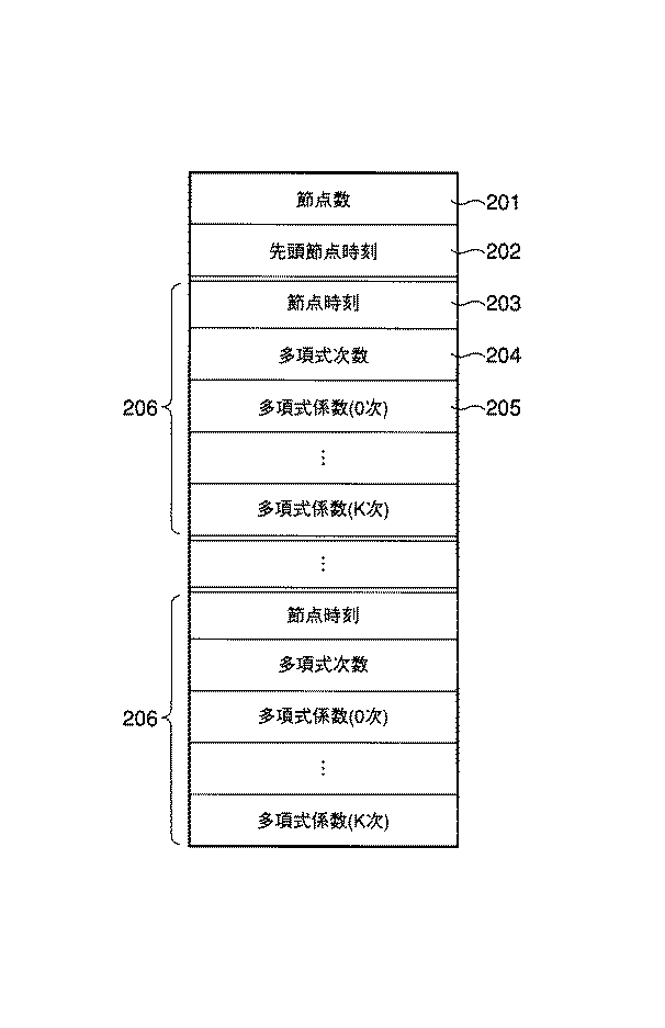
図6に、図5の時空間領域情報における各々の軌跡データ105のデータ構造の一例を示す。これは、スプライン関数などで関数補間された連続する軌跡を表すためのもので、時間とX座標やY座標などのパラメータとの関係を格納するためのものである。
【0044】
節点数201は、スプライン関数の節点の数を表しており、節点数−1個の多項式のデータ206があることを示している。スプライン関数は、隣接する節点の間の区間ごとにそれぞれ別の多項式で表現されるため、節点の数に対応した数の多項式が必要となる。したがって、節点フレーム番号、多項式の係数などを含むデータ206は、複数繰り返し記述される。
【0045】
先頭節点時刻202は、スプライン関数の最初の節点の時刻を表す。
【0046】
節点時刻203は、当該多項式データの終わりの節点時刻を表しており、この節点時刻まで多項式のデータ206が有効であることを示している。これはフレーム番号の代わりにタイムスタンプによって記述してもよい。多項式の係数データの数は、スプライン関数の最高次数により変化する(最高次数をKとすると、係数データの数はK+1となる)。そのため、係数データ数を多項式次数204に保存してある。多項式次数204の後には多項式次数+1個に相当する数の多項式係数205が続く。
【0047】
なお、時空間領域との間で通過判定を行う「参照軌跡」は、例えば、図6の軌跡データのデータ構造を用いて表現することができる。なお、図5の時空間領域情報における軌跡データのデータ構造と、参照軌跡のデータ構造とが異なっても構わない。
【0048】
また、参照軌跡の指定の方法については、外部から参照軌跡のデータを読み込む方法であってもよいし、ユーザが所定のツールを用いて参照軌跡のデータを記述する方法であってもよいし、ユーザがGUI画面上に表示された時空間において描いた軌跡をもとに参照軌跡のデータを生成する方法であってもよいし、それら以外の方法であってもよい。
【0049】
以下、本実施形態の時空間領域情報検索システムの構成例について詳しく説明する。
【0050】
ここでは、図5及び図6の時空間領域情報を通過判定の対象とする場合を例にとって説明する。
【0051】
図7に、本実施形態に係る時空間領域情報検索システムの構成例を示す。図7に示されるように、本時空間領域情報検索システムは、時空間領域情報記憶部301、内外判定部302、曲面交差判定部303、結果出力部304を備えている。
【0052】
この時空間領域情報検索システムは、計算機上でプログラムを実行する形で実現することができる。また、そのプログラムを、他のソフトウェアの一機能として組み込むようにすることも可能である。また、必要に応じて、その計算機に、所望の機能を有するOSやドライバソフト、パケット通信用ソフト、暗号ソフト等といったソフトウェア、あるいは通信インタフェース装置や外部記憶装置や入出力装置等といったハードウェアを搭載あるいは接続することができる。
【0053】
時空間領域情報記憶部301は、近似矩形もしくは近似多角形の各頂点の軌跡や近似楕円に外接する矩形の各頂点の軌跡などによって表された時空間領域情報が記憶されているもので、例えばハードディスクや光ディスク、半導体メモリなどで構成される。
【0054】
内外判定部302は、時空間領域が存在する時間のうち所定のフレームを取り出し、そのフレームにおける領域の形状を算出し、通過判定を行う参照軌跡の当該フレームにおける座標との内外判定を行う。なお、内外判定部302は、図7では、曲面交差判定部303の前段にあるが、その代わりに、曲面交差判定部303の後段にあってもよいし、互いに独立したプロセスとして曲面交差判定部303と並列に実行されるようにしてもよい。
【0055】
取り出すべき所定のフレームは、時空間領域が存在しているならば、どのフレームでもよい。例えば、領域形状の求めやすさから、時空間領域の先頭フレームを使用するようにしてもよい。
【0056】
時空間領域が矩形で表現されているなら、当該フレームの4頂点の座標p1〜p4を求める。時空間領域が多角形で表現されているなら、当該フレームの全頂点の座標p1〜pN(N:頂点数)を求める。時空間領域が楕円に外接する矩形で表現されているなら、当該フレームの外接矩形頂点の座標(p1〜p4)を求めて、楕円の中心点、長径・短径の長さ、傾きなど楕円のパラメータを求める。
【0057】
通過判定を行う参照軌跡の当該フレームにおける座標をrとすると、当該フレームの領域形状とrとの内外判定は、例えば以下のように行うことができる。
【0058】
(1)領域情報が矩形または多角形のとき
図8に示すように、多角形501と座標r(502)の内外判定となる。この場合の内外判定アルゴリズムは多数存在しており、どのような方法を利用してもよい。例えば、座標rから(多角形と交わる)直線503を引き、直線503が多角形の外周と何回交わるかを判定する。奇数回交わるなら座標rは多角形の内側、偶数回交わるなら多角形の外側である。図8の例では、右下の直線を用いたときは1回(左上の直線を用いたときは3回)交わっているので、座標rは多角形(すなわち対象となる時空間領域)の内部に存在すると判定される。
【0059】
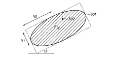
(2)領域情報が楕円のとき
図9に示すように、楕円601と座標r(602)の内外判定となる。この場合の内外判定アルゴリズムは多数存在しており、どのような方法を利用してもよい。図9の例においては、楕円601の中心点S=(Sx,Sy)、楕円の2軸の長さをV0,V1、回転角θとすると、楕円の内部は以下のように表すことができる。
P=(cosθ/V0)2+(sinθ/v1)2
Q=2*sinθ*cosθ*(1/V02−1/V12)
R=(sinθ/V0)2+(cosθ/v1)2
P*(x−Sx)2+Q*(x−Sx)*(y−Sy)+R*(y−Sy)2≦1
(x,y)にrの座標602を代入して、この不等式が成り立てば、rは楕円の内部にあり、不等式が成り立たなければ、rは楕円の外部にあることがわかる。図9の例では、上記の不等式が成り立ち、座標rは楕円(すなわち対象となる時空間領域)の内部に存在すると判定される。
【0060】
なお、楕円の外接矩形の頂点ベクトルをp1〜p4(pM=(pMx,pMy)とする)とすると、楕円の中心点ベクトルS=(Sx,Sy)、楕円の2軸の長さをV0,V1、回転角θは以下のように表すことができる(ただし、回転角に関しては、sinθ、cosθを求める)。
s=(p1+p3)/2
V0=|p2−p1|/2
v1=|p3−p2|/2
sinθ=(p2y−p1y)/(2*V0)
cosθ=(p2x−p1x)/(2*V0)
もちろん、時空間領域を近似する近似図形の形状や表現方法に応じて種々の内外判定方法があり、どのような内外判定方法を用いても構わない。なお、内外判定については、例えば、“「グラフィックスの数理」、杉原厚吉著、共立出版株式会社、1995年、pp.87-92”にて説明されている。
【0061】
曲面交差判定部303は、時空間領域の外周が張る曲面と参照軌跡との交差判定を行う。これは、時空間領域の外周を数式として表現し、参照軌跡を表す数式との方程式を解くことによって行う。
【0062】
領域形状が楕円の場合には、楕円外周全体を1つの数式で表せばよい(楕円外周全体を複数の数式で表しても構わない)。領域形状が矩形または多角形の場合には、各辺が張る曲面ごとに数式で表すものとする。時空間領域を表すための頂点軌跡データがスプライン関数で表現されている場合には、スプラインの節点間ごとに曲面を分割して数式で表す。
【0063】
頂点軌跡間にて同じ節点フレームが利用されている場合には、時空間領域が楕円のときは、(節点数−1)個の曲面、矩形のときは、(節点数−1)*4個の曲面、多角形のときは、(節点数−1)*(頂点数)個の曲面で表すことができる。なお、あるフレームにおいて、ある頂点は、そのフレームで節点となっていて、他の頂点は、節点となっていないときは、節点がない頂点軌跡の当該フレームに節点を追加したものとして扱うことによって、曲面を分割可能である。
【0064】
時空間領域の外周が張る曲面が複数の曲面で表される場合には、参照軌跡との交差判定を、全曲面についてそれぞれ行う。
【0065】
1つの曲面(時空間領域の外周が唯一の曲面で表現される場合の当該1つの曲面または時空間領域の外周が複数の曲面で表現される場合の個々の曲面)と、参照軌跡との交差判定処理は、例えば以下のように行うことができる。
【0066】
(1)領域情報が矩形または多角形のとき
図10に示すように、矩形または多角形における当該辺701の両端の頂点ベクトルの軌跡702,703を時間tの関数で表し、それぞれP(t),Q(t)とする。また、当該曲面の両端の節点時刻をt0,t1とする。このとき、曲面上の点Rの通過範囲は、パラメータkを利用して、
R(t,k)=P(t)+k*(Q(t)−P(t))
ただし、t0≦t≦t1,0≦k≦1
と表すことができる。
【0067】
参照軌跡ベクトルを時間tの関数r(t)とすると、
R(t,k)=r(t)
ただし、t0≦t≦t1,0≦k≦1
となる、t,kが存在するとき、当該曲面と指定された軌跡は、時刻tに交差する。よって、
P(t)+k*(Q(t)−P(t))−r(t)=0
をt,kについて解けばよい。
【0068】
P(t)=(Px(t),Py(t))
Q(t)=(Qx(t),Qy(t))
r(t)=(rx(t),ry(t))
とすると、
Px(t)+k*(Qx(t)−Px(t))−rx(t)=0
Py(t)+k*(Qy(t)−Py(t))−ry(t)=0
となり、t,kの連立方程式を解く問題に帰着する。ここで、kを消去すると、
(rx(t)−Px(t))*(Qy(t)−Py(t))−(ry(t)−Py(t))*(Qx(t)−Px(t))=0
となり、各軌跡がn次関数で表されているとすると、上記方程式は、(2*n)次方程式となる。これを解の公式などで解けばよい。また、高次方程式になった場合は、Newton法などで数値解を求めればよい。そして、t0≦t≦t1なる解について、kを評価し、0≦k≦1であれば、当該曲面と参照軌跡は、解となった時刻において交差することがわかる。
【0069】
各軌跡が任意の非線形関数のときも、上記方程式がNewton法などで解くことができれば、本手法を用いて交差判定を行うことができる。
【0070】
(2)領域情報が楕円のとき
図11に示すように、楕円801の中心点ベクトルの時刻tに対する軌跡を、S(t)=(Sx(t),Sy(t))、楕円の2軸の長さの軌跡をV0(t),V1(t)、回転角の軌跡をθ(t)とする。ここで、楕円の外接矩形の頂点ベクトルの軌跡を、p1(t)〜p4(t)(pM(t)=pMx(t),pMy(t)とする)とする。また、当該曲面の両端の節点時刻を、t0,t1とする。
【0071】
p21x(t)=p2x(t)−p1x(t)
p21y(t)=p2y(t)−p1y(t)
p32x(t)=p3x(t)−p2x(t)
p32y(t)=p3y(t)−p2y(t)
とすると、
S(t)=(p1(t)+p3(t))/2
v0(t)2={p21x(t)2+p21y(t)2}/4
v1(t)2={p32x(t)2+p32y(t)2}/4
sinθ(t)=p21y(t)/(2*v0(t))=p32x(t)/(2*v1(t))
cosθ(t)=p21x(t)/(2*v0(t))=p32y(t)/(2*v1(t))
となる。
【0072】
楕円の外周の軌跡を表す式は、
P(t)=(cosθ(t)/v0(t))2+(sinθ(t)/v1(t))2
Q(t)=2*sinθ(t)*cosθ(t)*(1/v0(t)2−1/v1(t)2)
R(t)=(sinθ(t)/v0(t))2+(cosθ(t)/v1(t))2
としたとき、
P(t)*(x−Sx(t))2+Q(t)*(x−Sx(t))*(y−Sy(t))+R(t)*(y
−Sy(t))2=1 …(1)
ただし、t0≦t≦t1
となる。
【0073】
参照軌跡ベクトルを時間r(t)=(rx(t),ry(t))とすると、
(x,y)=(rx(t),ry(t))としたとき、式(1)を満たすようなtが存在すれば、その時刻において楕円外周と参照軌跡は交差する。
【0074】
よって、
rsx(t)=rx(t)−Sx(t)
rsy(t)=ry(t)−Sy(t)
としたとき、
P(t)*rsx(t)2+Q(t)*rsx(t)*rsy(t)*(ry(t)−Sy(t))+R(t)*rsy(t
)2=1 …(2)
ただし、t0≦t≦t1
を解けばよい。
【0075】
P(t),Q(t),R(t)は、以下のように変形できる。
P(t)=4*(p21y(t)2+p32y(t)2)/{(p32x(t)2+p32y(t)2)*(p21x(t)2+p21y(t)2)}
Q(t)=8*(p32x(t)*p32y(t)−p21x(t)*p21y(t))/{(p32x(t)2+p32y(t)2)*(p21x(t)2+p21y(t)2)}
R(t)=4*(p21x(t)2+p32x(t)2)/{(p32x(t)2+p32y(t)2)*(p21x(t)2+p21y(t)2)}
これより、式(2)は、以下のように整理できる。
外形矩形の頂点軌跡および参照軌跡がn次関数で表されているとすると、式(3)は、(4*n)次方程式となる。これを解の公式などで解けばよい。また、高次方程式になった場合は、Newton法などで数値解を求めればよい。t0≦t≦t1なる解が存在すれば、当該曲面と参照軌跡は、解となった時刻において交差することがわかる。
【0076】
各軌跡が任意の非線形関数のときも、式(3)がNewton法などで解くことができれば、本手法を用いて交差判定を行うことができる。
【0077】
結果出力部304は、内外判定部302と曲面交差判定部303で得られた情報をもとに、時空間領域と参照軌跡の通過判定の結果を出力する。出力するデバイスは、ディスプレイやハードディスクあるいはネットワーク・インタフェースなど、どのようなものでもよい。また、本システムが、計算機上で動作するプログラムである場合に、通過判定の結果を、同一計算機上で動作する他のプロセスに出力してもよい。
【0078】
通過判定では、例えば、以下の処理が行われる。
【0079】
まず、曲面交差判定部303により、対象となる時空間領域の外周を表す全曲面について参照軌跡との交差判定を行うことにより、該時空間領域の外周と参照軌跡のすべての交点時刻t1〜tkが得られている。
【0080】
ここで、例えば、交点時刻ti〜ti+1において参照軌跡が該時空間領域の内部にあったとすれば、交点時刻ti-1〜tiとti+1〜ti+2には、参照軌跡は、該時空間領域の外部にあると考えることができる。逆に、交点時刻ti〜ti+1において参照軌跡が該時空間領域の外部にあたっとすれば、交点時刻ti-1〜tiとti+1〜ti+2には、参照軌跡は、該時空間領域の内部にあると考えることができる。すなわち、いずれかの時刻において参照軌跡が時空間領域の内部にあるか外部にあるかがわかれば、いずれの時刻についても参照軌跡が時空間領域の内部にあるか外部にあるかがわかる。
【0081】
しかして、内外判定部302により、該時空間領域が存在する時間内(先頭時刻=ts、最終時刻=teとする)の所定のフレーム(例えば先頭フレーム)において、参照軌跡が該時空間領域の内部にあるか外部にあるかがわかっている。
【0082】
そこで、結果出力部304は、内外判定部302により求められたフレームでの内外判定結果をもとに、曲面交差判定部303により求められた交点時刻t1〜tkから与えられる、当該時空間領域が存在する時間内の各々の期間ts〜t1、t1〜t2、…、tk-1〜tk、tk〜teについて、参照軌跡が該時空間領域の内部にあるか外部にあるかを特定する。
【0083】
ただし、曲面交差判定部303により交点時刻が1つも求まらなかった場合、すなわち参照軌跡が該時空間領域と交わらない場合には、内外判定部302により例えば先頭フレームが内部にある判定されたならば、参照軌跡は、当該時空間領域の全期間ts〜teにおいて常に該時空間領域の内部にあることがわかり、外部にあると判定されたならば、参照軌跡は、当該時空間領域の全期間ts〜teにおいて常に該時空間領域の外部にあることがわかる。
【0084】
通過判定結果としては、例えば、上記の各期間の開始の時刻または終了の時刻と、その期間において内部か外部かを示す情報との組を列挙することで、表現することができる。
【0085】
なお、上記に加えて、例えば、交点時刻において参照軌跡が該時空間領域と交わる位置を示す座標をも求めて、通過判定結果に含めて出力するようにしてもよい。
【0086】
また、例えば、該時空間領域が存在する時間に対する、参照軌跡が該時空間領域の内部に存在する時間の比などの、所定の評価値をも求めて、通過判定結果に含めて出力するようにしてもよい。
【0087】
なお、結果出力部304は、内外判定部302で得られた情報(例えば、先頭フレームにおける内外判定結果)と、曲面交差判定部303で得られた情報(例えば、交点時刻t1〜tk)を、そのまま出力する構成も可能である。
【0088】
図12に、本時空間領域情報検索システムにおける処理手順の一例を示す。図12に示されるように、本処理手順は、任意1フレームにおける内外判定を行うステップS43と、曲面通過判定を行うステップS42と、全曲面についてS42を実行したかを判別するステップS43と、通過判定処理を行ってその結果を出力するステップS42とを有する。
【0089】
なお、前述したように、ステップS41を、ステップS42およびステップS43のループ処理の後で行ってもよいし、ステップS41と、ステップS42およびステップS43のループ処理とを並列的に行ってもよい。
【0090】
ステップS41では、時空間領域が存在する時間のうち所定のフレームを取り出し、そのフレームにおける領域の形状を算出し、通過判定を行う軌跡の当該フレームにおける座標との内外判定を行う。ステップS42では、時空間領域の外周が張る曲面を頂点軌跡の節点および各辺で分割した曲面について、参照軌跡との交差判定を行う。ステップS43では、分割された全曲面について交差判定を行ったかどうか判別する。全曲面について交差判定が完了するまでループし、全曲面について交差判定が完了すれば終了する。ステップS42は、例えば、時空間領域が楕円のときは、(節点数−1)回、矩形のときは、(節点数−1)*4回、多角形のときは、(節点数−1)*(頂点数)回、実行される。ステップS44は、結果を出力するためのステップである。これは、ステップS42からステップS44までで得られた情報を要求に合わせて出力する。出力するデバイスは、ディスプレイやハードディスクなど、どのようなものでもよい。
【0091】
ところで、前述した処理例よりも簡易な通過判定結果を求める構成も可能である。
【0092】
例えば、参照軌跡が対象となる時空間領域と交わるか否かのみ求めて出力する方法がある。この場合には、交点時刻が1つでも求まれば、参照軌跡が該時空間領域と交わることが分かる。従って、まず、交点時刻が少なくとも1つ存在するか否かを調べればよい(例えば、各曲面について順次、参照軌跡との交点を求めていき、最初に参照軌跡が求まったところで、処理を終了する)。交点時刻が少なくとも1つ存在することが分かった場合には、内外判定は不要になる。次いで、交点時刻が1つも存在しないことが分かった場合(例えば、全曲面について、交点時刻が求まらなかった場合)には、ここではじめて内外判定を行い、内部と判定されたならば、参照軌跡が該時空間領域と交わることがわかり、外部と判定されたならば、参照軌跡が該時空間領域と交わらないことがわかる。
【0093】
また、複数の通過判定方法を用意し、例えば、目的などに応じて、適宜、使い分けて使用してもよい。例えば、詳細な通過判定方法と、簡易な通過判定方法を用意しておき、参照軌跡が該時空間領域と交わる全交点時刻が必要である場合には、前者の方法を使用し、参照軌跡が対象となる時空間領域と交わるか否かのみの情報が必要である場合には、後者を使用するようにしてもよい。また、例えば、対象とする時空間領域が多数ある場合に、最初に、後者の方法によって、参照軌跡と交わる時空間領域のみを抽出し、抽出された時空間領域のみを対象として、前者の方法により詳細に参照軌跡に対する通過判定処理を行うような方法もある。
【0094】
(第2の実施形態)
本実施形態では、図5とは異なるデータ構造の時空間領域情報に本発明を適用した場合について説明する。なお、本実施形態では、第1の実施形態と相違する点を中心に説明する。
【0095】
第1の実施形態では、代表点の位置データをフレームの進行に沿って並べたときの軌跡を所定の関数で近似し、該関数のパラメータを用いて記述された時空間領域情報を例にとったが、本実施形態では、代表点の基準となるフレームにおける位置データから、他のフレームにおける位置データへの領域変換を示す変換パラメータを求め、該変換パラメータについて、該変換パラメータをフレームの進行に沿って並べたときの軌跡を所定の関数で近似し、該関数のパラメータを用いて記述された時空間領域情報を例にとって説明する。
【0096】
図13に、時空間領域情報のデータ構造の他の例を示す。図13に示されるように、本例の時空間領域情報は、ID番号901、先頭時刻902、最終時刻903、参照領域フラグ904、参照領域形状情報905、変換形式フラグ906、軌跡データ907を含むものである。
【0097】
ID番号901と、先頭時刻902と、最終時刻903とは、図5におけるID番号101、先頭時刻102、最終時刻103のそれぞれと同等の意味を持つ。
【0098】
参照領域フラグ904は、参照領域の形状がどのように表現されているかを示すものである。参照領域の形状は、例えば、矩形、楕円、多角形などで表現されているため、それらを一意に区別するような情報が記述される。多角形の場合は、頂点数情報も参照領域フラグに付加される。
【0099】
参照領域形状情報905は、参照領域形状を格納するためのものである。例えば、参照領域形状が矩形や多角形のときは、各頂点の座標、参照領域形状が楕円のときは、外接矩形の頂点座標や、中心点、長軸短軸の長さなどのパラメータが格納される。
【0100】
変換形式フラグ906は、参照領域から各フレームにおける時空間領域情報への領域変換を示す変換パラメータがどのような形式で示されているかを示すものである。領域変換を示す変換パラメータの形式には、例えば、平行移動、一次変換、アフィン変換などがあるため、それらを一意に区別するような情報が記述される。
【0101】
軌跡データ907は、参照領域から各フレームにおける時空間領域情報への領域変換を示す変換パラメータのそれぞれの軌跡を記述するためのものである。軌跡データ907は、例えば、図6に示されるような軌跡データのデータ構造を持つ。変換パラメータは、複数持つことが多いため、軌跡データも変換パラメータの数だけ記述される。軌跡データの数は、変換形式フラグ907によって一意に決まり、例えば、平行移動のときは2つ、一次変換のときは4つ、アフィン変換のときは6つである。軌跡データの順番は、変換パラメータの意味によって決めておき、例えば、以下のようにする。
時刻tの関数であるパラメータの軌跡データがz1(t),z2(t),…と並んでいるとき、参照領域上のある点p=(px,py)が領域変換によって変換された軌跡を、P(t)=(Px(t),Py(t))とすると、
【0102】
パラメータの軌跡データz1(t),z2(t),…が、n次多項式で表されているとき、上式よりPx(t),Py(t)もやはりn次多項式で表すことが可能となる。
【0103】
なお、時空間領域との間で通過判定を行う「参照軌跡」は、例えば、図6の軌跡データのデータ構造を用いて表現することができる。なお、図5の時空間領域情報における軌跡データのデータ構造と、参照軌跡のデータ構造とが異なっても構わない。
【0104】
以下、本実施形態の時空間領域情報検索システムの構成例について詳しく説明する。
【0105】
ここでは、図13及び図6の時空間領域情報を通過判定の対象とする場合を例にとって説明する。
【0106】
図14に、この場合における時空間領域情報検索システムの構成例を示す。
【0107】
図14に示されるように、本時空間領域情報検索システムは、時空間領域情報記憶部1001、軌跡データ変換部1002、内外判定部1003、曲面交差判定部1004、結果出力部1005とを備えている。
【0108】
時空間領域情報記憶部1001は、参照領域と参照領域から該フレームにおける時空間領域情報への領域変換を示す変換パラメータにより記述した時空間領域情報が記憶されているもので、例えばハードディスクや光ディスク、半導体メモリなどで構成される。
【0109】
軌跡データ変換部1002は、参照領域と参照領域から該フレームにおける時空間領域情報への領域変換を示す変換パラメータにより記述した時空間領域情報を、近似矩形もしくは近似多角形の各頂点の軌跡や近似楕円に外接する矩形の各頂点の軌跡などによって表された時空間領域情報(すなわち、第1の実施形態の時空間領域情報(図5および図6))に変換する。
【0110】
参照領域は、矩形・多角形・楕円などで表されるため、矩形や多角形については、その各頂点座標を領域変換を示す変換パラメータの軌跡によって変換される軌跡を求める。楕円については、その外接矩形の各頂点座標を領域変換を示す変換パラメータの軌跡によって変換される軌跡を求める。参照領域上のある点P=(Px,Py)が、領域変換によって変換された軌跡P(t)=(Px(t),Py(t))は、式(4)のように計算できるため、領域変換を示す変換パラメータの軌跡がn次のスプライン関数で記述されていたとすると、軌跡データ変換部によって変換された各頂点の軌跡は、n次のスプライン関数となる。
【0111】
軌跡データ変換部1002と内外判定部1003と曲面交差判定部1004と結果出力部1005は、それぞれ、図7における内外判定部301、曲面交差判定部302、結果出力部303と同等の機能を持つ。軌跡データ変換部1002によって変換された時空間領域情報は、第1の実施形態における時空間領域情報と同等の情報を持つ。本実施形態の内外判定部1003や曲面交差判定部1004は、時空間領域情報記憶部1001に記憶されている時空間領域情報を処理対象とするのではなく、軌跡データ変換部1002により変換された後の時空間領域情報を処理対象とする点が、第1の実施形態と相違する。
【0112】
すなわち、本実施形態では、軌跡データ変換部1002が、参照領域と参照領域から該フレームにおける時空間領域情報への領域変換を示す変換パラメータにより記述した時空間領域情報を、近似矩形もしくは近似多角形の各頂点の軌跡や近似楕円に外接する矩形の各頂点の軌跡などによって表された時空間領域情報に変換した後は、第1の実施形態と同様の処理が行われる。
【0113】
図15に、本時空間領域情報検索システムにおける処理手順の一例を示す。図15に示されるように、本処理手順は、軌跡データを変換するステップS1101と、任意1フレームにおける内外判定を行うステップS1102と、曲面通過判定を行うステップS1103と、全曲面についてS1103を実行したかを判別するステップS1104と、通過判定処理を行ってその結果を出力するステップS1105で構成される。
【0114】
なお、前述したように、ステップS1102を、ステップS1103およびステップS1104のループ処理の後で行ってもよいし、ステップS1102と、ステップS1103およびステップS1104のループ処理とを並列的に行ってもよい。
【0115】
ステップS1101では、参照領域と参照領域から該フレームにおける時空間領域情報への領域変換を示す変換パラメータにより記述した時空間領域情報を、近似矩形もしくは近似多角形の各頂点の軌跡や近似楕円に外接する矩形の各頂点の軌跡などによって表された時空間領域情報に変換する。
【0116】
ステップS1102〜S1105は、第1の実施形態(図12)のステップS41〜S44と同様である。
【0117】
本実施形態によれば、参照領域と参照領域から該フレームにおける時空間領域情報への領域変換を示す変換パラメータにより記述した時空間領域情報においても、各代表点の軌跡として記述された時空間領域情報と同様に編集を行うことができる。
【0118】
もちろん、本時空間領域情報検索システムは、それらの他のデータ構造の時空間領域情報を扱うようにすることもできる。
【0119】
例えば、近似図形のある(1又は複数の)代表点については図5および図6のように当該代表点の位置データをフレームの進行に沿って並べたときの軌跡を所定の関数で近似し、該関数のパラメータを用いて記述し、それ以外の代表点については、同一フレームにおける他の代表点を基準としたときの当該代表点の相対的な位置を示すデータ(例えば、差分ベクトル)をフレームの進行に沿って並べたときの軌跡を所定の関数で近似し、該関数のパラメータを用いて記述した時空間領域情報についても、これを軌跡データ変換部1002によって、近似矩形もしくは近似多角形の各頂点の軌跡や近似楕円に外接する矩形の各頂点の軌跡などによって表された時空間領域情報に変換した後に処理を行えばよい。
【0120】
また、例えば、近似図形の(1又は複数の)代表点については図13および図6のように代表点の基準となるフレームにおける位置データから、他のフレームにおける位置データへの領域変換を示す変換パラメータを求め、該変換パラメータについて、該変換パラメータをフレームの進行に沿って並べたときの軌跡を所定の関数で近似し、該関数のパラメータを用いて記述し、それ以外の代表点については、同一フレームにおける他の代表点を基準としたときの当該代表点の相対的な位置を示すデータ(例えば、差分ベクトル)をフレームの進行に沿って並べたときの軌跡を所定の関数で近似し、該関数のパラメータを用いて記述した時空間領域情報についても、これを軌跡データ変換部1002によって、近似矩形もしくは近似多角形の各頂点の軌跡や近似楕円に外接する矩形の各頂点の軌跡などによって表された時空間領域情報に変換した後に処理を行えばよい。
【0121】
また、本時空間領域情報検索システムは、複数種類のデータ構造の時空間領域情報を扱うようにすることもできる。この場合には、時空間領域情報に、データ構造を識別するための識別情報を付加し、時空間領域情報処理システムは、時空間領域情報を処理するに際して、その識別情報を参照して、データ構造を特定し、そのデータ構造に応じた処理を行うようにすればよい。
【0122】
なお、以上の各機能は、ソフトウェアとして実現可能である。
また、本実施形態は、コンピュータに所定の手段を実行させるための(あるいはコンピュータを所定の手段として機能させるための、あるいはコンピュータに所定の機能を実現させるための)プログラムとして実施することもでき、該プログラムを記録したコンピュータ読取り可能な記録媒体として実施することもできる。
【0123】
なお、この発明の実施の形態で例示した構成は一例であって、それ以外の構成を排除する趣旨のものではなく、例示した構成の一部を他のもので置き換えたり、例示した構成の一部を省いたり、例示した構成に別の機能あるいは要素を付加したり、それらを組み合わせたりすることなどによって得られる別の構成も可能である。また、例示した構成と論理的に等価な別の構成、例示した構成と論理的に等価な部分を含む別の構成、例示した構成の要部と論理的に等価な別の構成なども可能である。また、例示した構成と同一もしくは類似の目的を達成する別の構成、例示した構成と同一もしくは類似の効果を奏する別の構成なども可能である。
また、この発明の実施の形態で例示した各種構成部分についての各種バリエーションは、適宜組み合わせて実施することが可能である。
また、この発明の実施の形態は、個別装置としての発明、個別装置内部の構成部分についての発明、またはそれらに対応する方法の発明等、種々の観点、段階、概念またはカテゴリに係る発明を包含・内在するものである。
従って、この発明の実施の形態に開示した内容からは、例示した構成に限定されることなく発明を抽出することができるものである。
【0124】
本発明は、上述した実施の形態に限定されるものではなく、その技術的範囲において種々変形して実施することができる。
【0125】
【発明の効果】
本発明によれば、映像データ中の複数フレームにわたる任意の時空間領域を指定された軌跡が通過するかどうかを高速かつ効率的に判別し、通過する時刻情報を抽出することが可能になる。
【図面の簡単な説明】
【図1】映像中の物体の領域を物体領域データで記述するための処理の概要を説明するための図
【図2】基準代表点のX座標の値を近似する関数を求める例を説明するための図
【図3】基準代表点以外の代表点を表すための差分ベクトルの一例を説明するための図
【図4】基準代表点以外の代表点を表すための差分ベクトルのX成分の値を近似する関数を求める例を説明するための図
【図5】時空間領域情報のデータ構造の一例を示す図
【図6】軌跡データのデータ構造の一例を示す図
【図7】本発明の一実施形態に係る時空間領域情報検索システムの構成例を示す図
【図8】多角形と座標の内外判定方法の一例を示す図
【図9】楕円と座標の内外判定方法の一例を示す図
【図10】矩形または多角形の一辺の軌跡と指定された軌跡の交差判定方法を示す図
【図11】楕円外周の軌跡と指定された軌跡の交差判定方法を示す図
【図12】同実施形態に係る時空間領域情報検索システムの処理手順の一例を示すフローチャート
【図13】時空間領域情報のデータ構造の一例を示す図
【図14】同実施形態に係る時空間領域情報検索システムの他の構成例を示す図
【図15】同実施形態に係る時空間領域情報検索システムの処理手順の他の例を示すフローチャート
【符号の説明】
301,1001…時空間領域情報記憶部
1002…軌跡データ変換部
302,1003…内外判定部
303,1004…曲面交差判定部
304,1005…結果出力部[0001]
BACKGROUND OF THE INVENTION
The present invention relates to a method of processing spatio-temporal region information for determining passability with respect to a reference locus of spatio-temporal region information in a video.
[0002]
[Prior art]
In recent years, with the rapid development of video image processing technology, it has become common to handle video and images as digital data. This digitization has established a technique for efficiently compressing video image data having a large amount of data. With the development of network technologies such as the Internet, satellite broadcasting, and CATV, a large amount of video data can be handled, and video and image information can be stored and extracted and used according to needs. Video image database systems and video-on-demand are entering the practical stage. In addition, automatic monitoring systems from remote locations are becoming major. In this way, when trying to use a video or an image, there is a demand for recognizing what is in the screen, searching for a video that has a desired object, or classifying the video.
[0003]
In order to respond to such a demand, a method for efficiently generating and storing an arbitrary spatiotemporal region over a plurality of frames in a video has already been proposed (for example, Japanese Patent Application Laid-Open Nos. 2001-118075 and 2001-2001). 111996).
[0004]
[Problems to be solved by the invention]
However, in the conventional technique for searching and extracting and classifying a spatio-temporal region based on the position and movement of the spatio-temporal region, it is necessary to determine whether or not the region satisfies the condition for all frames in which the spatio-temporal region exists. For this reason, when the number of frames in the spatio-temporal region is large, or when searching from a large number of spatio-temporal regions, there is a drawback that the calculation amount is large and the efficiency is low.
[0005]
The present invention has been made in consideration of the above circumstances, and provides a processing method of spatio-temporal region information capable of quickly and efficiently performing passage determination between a spatio-temporal region and a designated arbitrary locus. With the goal.
[0006]
[Means for Solving the Problems]
The present invention is directed to spatio-temporal region information described as representing a spatio-temporal region, which is a transition over a plurality of frames in an arbitrary region in video data, and capable of specifying a locus of a representative point of an approximate figure representing the region. Whether the surface portion of the spatio-temporal region specified by the trajectory of the representative point of the approximate figure intersects the reference trajectory specified as a spatio-temporal curve For a predetermined frame in which the spatio-temporal region exists, and the coordinates of the reference trajectory in the predetermined frame are present inside or outside the approximate figure in the predetermined frame. And an internal / external determination step for determining whether or not it exists.
[0007]
Preferably, based on the determination result obtained by the intersection determination step and the determination result obtained by the inside / outside determination step, an output step for outputting information related to the passage of the spatiotemporal region with respect to the reference trajectory. You may make it have.
[0008]
Preferably, the intersection determination step obtains information ti (i = 1 to the number of times of intersection) of the time when the reference locus intersects the surface portion of the region, and the inside / outside determination step includes the spatiotemporal region. When the frame at the start time ts is determined, the output step is determined to be present inside by the inside / outside determination step when a plurality of pieces of information on the intersection time are obtained by the intersection determination step. , During every other period including the period ts to t1, information indicating that the spatiotemporal region passes through the reference trajectory is output, and when it is determined by the inside / outside determination step that it exists outside, Information indicating that the spatiotemporal region passes through the reference trajectory may be output in every other period including the period t1 to t2.
[0009]
Preferably, in the output step, when one piece of information of the intersection time is obtained by the intersection determination step, and when it is determined that the information exists inside by the inside / outside determination step, the top where the spatiotemporal region exists In the period from the time to the obtained time, information indicating that the spatio-temporal region passes through the reference trajectory is output, and when the inside / outside determination step determines that it exists outside, the obtained information is obtained. Information indicating that the spatiotemporal region passes through the reference trajectory may be output during a period from time to the final time when the spatiotemporal region exists.
[0010]
Preferably, the output step always sets the reference trajectory to the time when it is determined by the inside / outside determination step that no information on the time of intersection is obtained by the intersection determination step. Outputs information indicating that the space area passes, and outputs information indicating that the spatiotemporal area does not always pass through the reference trajectory when it is determined by the inside / outside determination step that the space area exists outside. Also good.
[0011]
Preferably, the time domain information is described using parameters of the function by approximating a trajectory when the position data of the representative points are arranged along the progress of the frame with a predetermined function. May be.
[0012]
Preferably, regardless of the format of the target spatio-temporal region information, for all the representative points, the locus when the position data of the representative points are arranged along the progress of the frame is approximated by a predetermined function, The method further includes a conversion step of converting into a function described using function parameters, wherein the intersection determination step and the inside / outside determination step are performed on the spatio-temporal region information after being converted by the conversion step. It may be.
[0013]
The present invention also describes spatio-temporal region information that can describe a trajectory of a representative point of an approximate figure representing the region described as representing a spatio-temporal region that is a transition over a plurality of frames in an arbitrary region in video data. A spatio-temporal region information processing apparatus for a target, wherein a surface portion of the spatio-temporal region specified by a trajectory of a representative point of the approximate figure intersects a reference trajectory specified as a spatio-temporal curve Intersection determination means for determining whether or not, for a predetermined frame where the spatiotemporal region exists, whether the coordinates of the reference trajectory in the predetermined frame exist within the approximate figure in the predetermined frame An inside / outside determination means for determining whether or not the outside exists is provided.
[0014]
For example, the trajectory of a representative point of an approximate figure (for example, each vertex of a rectangle circumscribing or inscribed to an approximate figure, an approximate polygon, or an approximate ellipse) and the specified trajectory at all times when the spatiotemporal region exists Assuming that the trajectory is continuous, in the intersection determination of the specified trajectory with the curved surface extending the outer periphery of the spatiotemporal region, when the specified trajectory intersects the curved surface, the trajectory specified at the time of intersection Either the space-time area has moved from the inside to the outside, or it has moved from the outside to the inside. If the trajectory specified at all times in which the spatiotemporal region exists is inside or outside the spatiotemporal region, the coordinates in the specified trajectory and the coordinates of the specified trajectory in that frame It is possible to determine whether the trajectory designated at all times when the spatio-temporal region exists is inside or outside the spatio-temporal region. Assuming that all the region conversion parameters from the reference region to the spatio-temporal region in each frame are continuous, the trajectory in which each vertex moves according to the region conversion parameter is also continuous. Therefore, it is possible to apply each process after calculating the vertex trajectory in advance.
[0015]
According to the present invention, it is not necessary to perform inside / outside determination for all frames in which a spatiotemporal region exists unlike the conventional method, and it is possible to perform passage determination of a trajectory designated as a spatiotemporal region at high speed and efficiently. Become.
[0016]
The present invention relating to the apparatus is also established as an invention relating to a method, and the present invention relating to a method is also established as an invention relating to an apparatus.
Further, the present invention relating to an apparatus or a method has a function for causing a computer to execute a procedure corresponding to the invention (or for causing a computer to function as a means corresponding to the invention, or for a computer to have a function corresponding to the invention. It is also established as a program (for realizing) and also as a computer-readable recording medium on which the program is recorded.
[0017]
DETAILED DESCRIPTION OF THE INVENTION
Hereinafter, embodiments of the invention will be described with reference to the drawings.
[0018]
(First embodiment)
The spatiotemporal region information search system according to the embodiment of the present invention relates to a relationship between a target spatiotemporal region and a specified trajectory (hereinafter referred to as a reference trajectory), for example, the target spatiotemporal region is referred to. Whether to pass the trajectory, or the time when the target space-time area passes the reference trajectory in more detail (time stamp, frame number, etc.) or the period when the reference trajectory is inside and outside the target space-time area This is a system having a function for determining.
[0019]
First, the spatio-temporal region information will be briefly described.
[0020]
Note that the contents, generation method, usage method, and the like of the spatio-temporal region information are disclosed in detail in, for example, Japanese Patent Application Laid-Open Nos. 2001-1118075 and 2001-111996 (the objects disclosed in them). The area data corresponds to one form of this space-time area information).
[0021]
First, the contents of the spatio-temporal region information and the generation method will be briefly described.
[0022]
The spatio-temporal region information is a temporal and spatial region from the appearance to disappearance of a specific region provided on a display screen (for example, a GUI screen) for various purposes (for example, temporal transition of a two-dimensional region in each frame). ). The spatio-temporal region information is usually information attached to the video data (or moving image data) (the content of the video data itself is a real image, a real image processed, a CG, an animation, Any content, such as a combination) The video data will be described assuming that the video data consists of a plurality of frames.
[0023]
This specific area can be used as an area indicating a specific object (object) existing in the video data, for example. In this case, the shape of the specific area in a frame represents (or approximates) the specific object area in the frame. Here, the object region is a group of regions in the image, such as a person, an animal, a plant, a car, a building, a road, a river, the sun, a cloud, etc. (or a part thereof such as a human head, a car, etc. Anything that can be understood as an object can be handled. Moreover, it may be independent, may be a part of a thing (for example, a person's head, a car hood, a building entrance), or may be a group of things (for example, a group of birds or fish). .
[0024]
Next, generation of spatiotemporal region information for one object region will be briefly described with reference to FIGS. 1 and 2.
[0025]
First, generation of spatio-temporal region information can be roughly performed by the following procedure, for example. In addition, any procedure can be automated, and it is also possible to intervene a user's manual work.
(1) Extract an object region of a target object from a predetermined frame of video data.
(2) The object area is approximated by a predetermined figure.
(3) A representative point that identifies the approximate figure is extracted.
The
(4) For each representative point, the time series of the position (or the amount by which this can be specified) is expressed by a function (approximate function) such as time t (for example, a time stamp given to the video) or frame number f. Approximate expression. The value of the parameter of the function when this approximate expression is obtained is the value to be obtained. This function is expressed separately for each representative point and separately for the X and Y coordinates.
[0026]
The procedure of 1-4 is performed about each object area | region used as object.
[0027]
There are various types of approximate figures such as a polygon whose number of sides is a parameter, a polygon such as a rectangle with a fixed number of sides, a circle, an ellipse, and the like. The representative points include, for example, polygon vertices, four or three vertices of a rectangle, one point on the center and circumference of a circle, or both end points of a circle diameter, four or three of a circumscribed rectangle of an ellipse. There are various types depending on the type of figure, such as two vertices (which may be four or three vertices of an inscribed rectangle) or two focal points of the ellipse and one point on the ellipse.
[0028]
If the parameters of this function are stored, the function is obtained from the parameters, and the XY coordinate value of each representative point at a desired time t or frame number f is obtained based on the function. From the XY coordinate values of the points, the approximate figure region at the desired time t or frame number f can be obtained.
[0029]
1 and 2 use a polygon as an approximate figure for an object region, use representative points as polygon vertices, and use a quadratic polynomial spline function as an approximation function for the trajectory of each vertex in the time axis direction. It is an example which produces | generates the spatio-temporal area | region information with respect to the object "fish" in an image.
[0030]
In FIG. 1A,
[0031]
FIG. 1B shows a representative point of an approximate figure over a plurality of frames, that is, the transition of the
[0032]
In FIG. 1C, 24 represents the representative point V.0Is an example of the function obtained for (reference representative point V here)0Only one coordinate axis is shown). This example shows a case where the approximate interval is divided into two, t = 0 to 5 and t = 5 to 16.
[0033]
2 shows a representative point V0It is an example which is calculating | requiring the function which approximates the value of X coordinate of. 31 in the figure represents a time interval in which an object exists, and a black dot (32) is a representative point V.0X coordinate value. 33 is the approximate function. An approximate function is similarly obtained for the Y coordinate. Since a polynomial spline function is used as an approximation function, a polynomial is defined for each time section divided by points called nodes in 24 of FIG. Here, t = 0, 5, and 16 are the node times.
[0034]
Representative point V0The same applies to other representative points.
[0035]
On the other hand, representative point V0For other representative points, there is a method in which the representative point is expressed by a relative relationship from a representative point different from the representative point, for example, a difference vector, and described by a locus of the vector. As an example, FIG. 3 shows a representative point V as a reference in an approximate polygon.0FIG. 5 is a diagram illustrating each of difference vectors for representing other representative points. The black dot sequence (42) in FIG.0,1Represents the value of the X component.
[0036]
Further, in the above, the position of the representative point or the difference vector trajectory in each frame is approximated, but the function for converting the position or difference vector of the representative point in a certain reference frame to the position or difference vector of the representative point in each frame There is also a method of approximating the locus of parameters. Alternatively, there is a method of approximating the parameter trajectory of a function that converts the position or difference vector of the representative point in the preceding frame to the position or difference vector of the representative point in the subsequent frame.
[0037]
In addition, there are various variations in the form of the spatiotemporal region information, and the present invention can be applied to any form of spatiotemporal region information.
The spatiotemporal region information includes, for example, each representative point corresponding to each object region and each frame, each object region and each frame, each representative point of each object region, or each Predetermined attribute information or related information may be added in a predetermined unit such as for each object area. The present invention is also applicable to such spatiotemporal region information.
[0038]
FIG. 5 shows an example of the data structure of the spatiotemporal region information used in the description of the present embodiment. As shown in FIG. 5, the spatiotemporal region information of this example includes spatiotemporal region information identification information (hereinafter referred to as an ID number) 101, a
[0039]
The
[0040]
The
[0041]
The
[0042]
The
[0043]
FIG. 6 shows an example of the data structure of each
[0044]
The number of
[0045]
The leading
[0046]
The
[0047]
Note that the “reference trajectory” for performing passage determination with respect to the spatio-temporal region can be expressed using, for example, the data structure of the trajectory data in FIG. Note that the data structure of the trajectory data in the spatiotemporal region information in FIG. 5 may be different from the data structure of the reference trajectory.
[0048]
In addition, the method for specifying the reference locus may be a method of reading the reference locus data from the outside, or a method in which the user describes the reference locus data using a predetermined tool, It may be a method of generating reference trajectory data based on a trajectory drawn in time and space displayed on the GUI screen by the user, or a method other than those.
[0049]
Hereinafter, a configuration example of the spatio-temporal region information search system of the present embodiment will be described in detail.
[0050]
Here, a case where the spatio-temporal region information of FIGS. 5 and 6 is a subject of passage determination will be described as an example.
[0051]
FIG. 7 shows a configuration example of the spatio-temporal region information search system according to the present embodiment. As shown in FIG. 7, the spatiotemporal region information search system includes a spatiotemporal region information storage unit 301, an inside /
[0052]
This spatio-temporal region information retrieval system can be realized by executing a program on a computer. It is also possible to incorporate the program as a function of other software. In addition, if necessary, the computer is equipped with an OS, driver software, software for packet communication, encryption software, etc. having a desired function, or hardware such as a communication interface device, external storage device, input / output device, etc. Alternatively, they can be connected.
[0053]
The spatio-temporal region information storage unit 301 stores spatio-temporal region information represented by the locus of each vertex of an approximate rectangle or approximate polygon or the locus of each vertex of a rectangle circumscribing the approximate ellipse. It is composed of a hard disk, optical disk, semiconductor memory, and the like.
[0054]
The inside /
[0055]
The predetermined frame to be taken out may be any frame as long as a space-time area exists. For example, the top frame of the spatio-temporal region may be used for ease of obtaining the region shape.
[0056]
If the spatiotemporal region is represented by a rectangle, the coordinates p1 to p4 of the four vertices of the frame are obtained. If the spatiotemporal region is represented by a polygon, the coordinates p1 to pN (N: number of vertices) of all the vertices of the frame are obtained. If the spatio-temporal region is expressed by a rectangle circumscribing the ellipse, the coordinates (p1 to p4) of the circumscribed rectangle vertex of the frame are obtained, and the ellipse center point, the length of the major axis / minor axis, the inclination, etc. Find the parameters.
[0057]
If the coordinate in the frame of the reference trajectory for which the passage determination is performed is r, the inside / outside determination between the region shape of the frame and r can be performed as follows, for example.
[0058]
(1) When the area information is rectangular or polygonal
As shown in FIG. 8, the inside / outside determination of the
[0059]
(2) When the area information is an ellipse
As shown in FIG. 9, the inside / outside determination of the
P = (cosθ / V0)2+ (Sinθ / v1)2
Q = 2 * sinθ * cosθ * (1 / V02-1 / V12)
R = (sinθ / V0)2+ (Cosθ / v1)2
P * (x-Sx)2+ Q * (x-Sx) * (y-Sy) + R * (y-Sy)2≦ 1
If r coordinates 602 are substituted for (x, y) and this inequality holds, r is inside the ellipse, and if the inequality does not hold, r is outside the ellipse. In the example of FIG. 9, the above inequality holds, and it is determined that the coordinate r exists inside the ellipse (that is, the target space-time region).
[0060]
If the vertex vectors of the circumscribed rectangle of the ellipse are p1 to p4 (pM = (pMx, pMy)), the ellipse center point vector S = (Sx, Sy), the length of the ellipse's two axes is V0, V1 and the rotation angle θ can be expressed as follows (however, regarding the rotation angle, sin θ and cos θ are obtained).
s = (p1 + p3) / 2
V0 = | p2-p1 | / 2
v1 = | p3-p2 | / 2
sinθ = (p2y-p1y) / (2 * V0)
cos θ = (p2x−p1x) / (2 * V0)
Of course, there are various inside / outside determination methods depending on the shape and expression method of the approximate figure that approximates the spatiotemporal region, and any inside / outside determination method may be used. As for the inside / outside determination, for example, “Mathematics of graphics”, Atsuyoshi Sugihara, Kyoritsu Publishing Co., Ltd., 1995, pp. 87-92 ".
[0061]
The curved surface
[0062]
When the area shape is an ellipse, the entire circumference of the ellipse may be represented by one mathematical expression (the entire circumference of the ellipse may be represented by a plurality of mathematical expressions). When the area shape is a rectangle or a polygon, each curved surface stretched by each side is expressed by a mathematical expression. When the vertex trajectory data for representing the spatio-temporal region is expressed by a spline function, the curved surface is divided between the nodes of the spline and expressed by an equation.
[0063]
When the same nodal frame is used between the vertex trajectories, if the spatiotemporal region is an ellipse, (number of nodes-1) curved surfaces, and if it is a rectangle, (number of nodes-1) * 4 Can be expressed by (number of nodes-1) * (number of vertices). In a certain frame, if a vertex is a node in that frame, and other vertices are not nodes, treat it as a node added to the frame of the vertex trajectory where there are no nodes. The curved surface can be divided.
[0064]
When the curved surface extending from the outer periphery of the spatio-temporal region is represented by a plurality of curved surfaces, the intersection determination with the reference locus is performed for all the curved surfaces.
[0065]
Intersection of one curved surface (one curved surface when the outer periphery of the spatio-temporal region is expressed by a single curved surface or individual curved surfaces when the outer periphery of the spatio-temporal region is expressed by a plurality of curved surfaces) and the reference locus The determination process can be performed as follows, for example.
[0066]
(1) When the area information is rectangular or polygonal
As shown in FIG. 10, the
R (t, k) = P (t) + k * (Q (t) -P (t))
However, t0 ≦ t ≦ t1, 0 ≦ k ≦ 1
It can be expressed as.
[0067]
If the reference trajectory vector is a function r (t) of time t,
R (t, k) = r (t)
However, t0 ≦ t ≦ t1, 0 ≦ k ≦ 1
When t and k exist, the locus specified as the curved surface intersects at time t. Therefore,
P (t) + k * (Q (t) -P (t))-r (t) = 0
Can be solved for t and k.
[0068]
P (t) = (Px (t), Py (t))
Q (t) = (Qx (t), Qy (t))
r (t) = (rx (t), ry (t))
Then,
Px (t) + k * (Qx (t) -Px (t))-rx (t) = 0
Py (t) + k * (Qy (t) -Py (t))-ry (t) = 0
This results in a problem of solving simultaneous equations of t and k. Here, if k is deleted,
(Rx (t) -Px (t)) * (Qy (t) -Py (t))-(ry (t) -Py (t)) * (Qx (t) -Px (t)) = 0
Assuming that each locus is represented by an n-order function, the above equation becomes a (2 * n) -order equation. This can be solved with a solution formula. If a higher order equation is obtained, a numerical solution may be obtained by the Newton method or the like. Then, k is evaluated for a solution satisfying t0 ≦ t ≦ t1, and if 0 ≦ k ≦ 1, it can be seen that the curved surface and the reference locus intersect at the time when the solution is obtained.
[0069]
Even when each trajectory is an arbitrary nonlinear function, if the above equation can be solved by the Newton method or the like, the intersection determination can be performed using this method.
[0070]
(2) When the area information is an ellipse
As shown in FIG. 11, the locus of the center point vector of the
[0071]
p21x (t) = p2x (t) -p1x (t)
p21y (t) = p2y (t) -p1y (t)
p32x (t) = p3x (t) -p2x (t)
p32y (t) = p3y (t) -p2y (t)
Then,
S (t) = (p1 (t) + p3 (t)) / 2
v0 (t)2= {P21x (t)2+ P21y (t)2} / 4
v1 (t)2= {P32x (t)2+ P32y (t)2} / 4
sinθ (t) = p21y (t) / (2 * v0 (t)) = p32x (t) / (2 * v1 (t))
cosθ (t) = p21x (t) / (2 * v0 (t)) = p32y (t) / (2 * v1 (t))
It becomes.
[0072]
The equation representing the trajectory of the circumference of the ellipse is
P (t) = (cosθ (t) / v0 (t))2+ (Sinθ (t) / v1 (t))2
Q (t) = 2 * sinθ (t) * cosθ (t) * (1 / v0 (t)2-1 / v1 (t)2)
R (t) = (sinθ (t) / v0 (t))2+ (Cosθ (t) / v1 (t))2
When
P (t) * (x-Sx (t))2+ Q (t) * (x-Sx (t)) * (y-Sy (t)) + R (t) * (y
-Sy (t))2= 1 (1)
However, t0≤t≤t1
It becomes.
[0073]
If the reference trajectory vector is time r (t) = (rx (t), ry (t)),
When (x, y) = (rx (t), ry (t)), if there is a t that satisfies equation (1), the outer circumference of the ellipse and the reference locus intersect at that time.
[0074]
Therefore,
rsx (t) = rx (t) −Sx (t)
rsy (t) = ry (t) −Sy (t)
When
P (t) * rsx (t)2+ Q (t) * rsx (t) * rsy (t) * (ry (t) -Sy (t)) + R (t) * rsy (t
)2= 1 (2)
However, t0≤t≤t1
Can be solved.
[0075]
P (t), Q (t), and R (t) can be modified as follows.
P (t) = 4 * (p21y (t)2+ P32y (t)2) / {(P32x (t)2+ P32y (t)2) * (P21x (t)2+ P21y (t)2)}
Q (t) = 8 * (p32x (t) * p32y (t) −p21x (t) * p21y (t)) / {(p32x (t)2+ P32y (t)2) * (P21x (t)2+ P21y (t)2)}
R (t) = 4 * (p21x (t)2+ P32x (t)2) / {(P32x (t)2+ P32y (t)2) * (P21x (t)2+ P21y (t)2)}
Thus, equation (2) can be organized as follows.
Assuming that the vertex trajectory and the reference trajectory of the outline rectangle are expressed by an n-order function, Equation (3) becomes a (4 * n) -order equation. This can be solved with a solution formula. If a higher order equation is obtained, a numerical solution may be obtained by the Newton method or the like. If there is a solution of t0 ≦ t ≦ t1, it can be seen that the curved surface and the reference locus intersect at the time of solution.
[0076]
Even when each locus is an arbitrary non-linear function, if this equation (3) can be solved by the Newton method or the like, the intersection determination can be performed using this method.
[0077]
The
[0078]
In the passage determination, for example, the following processing is performed.
[0079]
First, the curved surface
[0080]
Here, for example, if the reference trajectory is inside the spatio-temporal region at the intersection times ti to ti + 1, the reference trajectory at the intersection times ti-1 to ti and ti + 1 to ti + 2 is It can be considered to be outside the spatiotemporal region. Conversely, if the reference trajectory falls outside the spatiotemporal region at the intersection times ti to ti + 1, the reference trajectory at the intersection times ti-1 to ti and ti + 1 to ti + 2 It can be considered to be inside the spatial domain. That is, if it is known whether the reference trajectory is inside or outside the spatiotemporal region at any time, it can be determined whether the reference trajectory is inside or outside the spatiotemporal region at any time.
[0081]
Thus, the inside /
[0082]
Therefore, the
[0083]
However, when no intersection time is obtained by the curved surface
[0084]
The passage determination result can be expressed, for example, by listing a set of a start time or an end time of each period and information indicating whether the period is internal or external.
[0085]
In addition to the above, for example, coordinates indicating the position where the reference locus intersects the spatiotemporal region at the intersection time may be obtained and included in the passage determination result and output.
[0086]
In addition, for example, a predetermined evaluation value such as a ratio of the time when the reference trajectory exists inside the spatiotemporal region to the time when the spatiotemporal region exists is also obtained and included in the passage determination result and output. It may be.
[0087]
The
[0088]
FIG. 12 shows an example of a processing procedure in this space-time area information search system. As shown in FIG. 12, this processing procedure includes step S43 for determining inside / outside in an arbitrary frame, step S42 for determining curved surface passage, step S43 for determining whether S42 has been executed for all curved surfaces, and passing. Step S42 for performing a determination process and outputting the result.
[0089]
As described above, step S41 may be performed after the loop processing of step S42 and step S43, or the loop processing of step S41 and step S42 and step S43 may be performed in parallel.
[0090]
In step S41, a predetermined frame is extracted from the time in which the spatiotemporal region exists, the shape of the region in the frame is calculated, and the inside / outside determination with respect to the coordinates of the trajectory for the passage determination is performed. In step S42, intersection determination with the reference trajectory is performed on the curved surface formed by dividing the outer circumference of the spatio-temporal region at the nodes and each side of the vertex trajectory. In step S43, it is determined whether or not the intersection determination has been performed for all the divided curved surfaces. The process loops until intersection determination is completed for all curved surfaces, and ends when intersection determination is completed for all curved surfaces. Step S42 is, for example, (number of nodes-1) times when the spatiotemporal region is an ellipse, (number of nodes-1) * 4 times when the space is rectangular, and (number of nodes-1) when it is a polygon. * (Number of vertices) is executed. Step S44 is a step for outputting the result. This outputs the information obtained in steps S42 to S44 according to the request. The output device may be any device such as a display or a hard disk.
[0091]
By the way, the structure which calculates | requires a passage determination result simpler than the process example mentioned above is also possible.
[0092]
For example, there is a method of obtaining and outputting only whether or not the reference trajectory intersects the target spatiotemporal region. In this case, if even one intersection time is obtained, it can be understood that the reference trajectory intersects with the spatiotemporal region. Therefore, it is sufficient to first check whether or not there is at least one intersection time (for example, for each curved surface, the intersection with the reference trajectory is sequentially obtained, and the process is terminated when the reference trajectory is first obtained. ). When it is found that at least one intersection time exists, the inside / outside determination is not necessary. Next, when it is found that there is no intersection time (for example, when the intersection time is not obtained for all curved surfaces), the inside / outside determination is performed for the first time here, It can be seen that the reference trajectory intersects with the spatiotemporal region. If it is determined that the reference trajectory is outside, it can be seen that the reference trajectory does not intersect with the spatiotemporal region.
[0093]
Also, a plurality of passage determination methods may be prepared, and may be used appropriately according to the purpose, for example. For example, if a detailed passage determination method and a simple passage determination method are prepared and the time of all intersections where the reference locus intersects the spatio-temporal region is required, the former method is used and the reference locus is In the case where information only on whether or not to intersect with the target space-time region is necessary, the latter may be used. Also, for example, when there are a large number of target spatiotemporal regions, first, only the spatiotemporal region that intersects the reference trajectory is first extracted by the latter method, and only the extracted spatiotemporal region is targeted. There is also a method for performing the passage determination process for the reference trajectory in more detail.
[0094]
(Second Embodiment)
In the present embodiment, a case will be described in which the present invention is applied to spatiotemporal region information having a data structure different from that in FIG. In the present embodiment, the description will be focused on differences from the first embodiment.
[0095]
In the first embodiment, the locus when the position data of representative points are arranged along the progress of the frame is approximated by a predetermined function, and the spatio-temporal region information described using the parameters of the function is taken as an example. However, in the present embodiment, a conversion parameter indicating region conversion from position data in a frame serving as a reference point of a representative point to position data in another frame is obtained, and the conversion parameter is set to the progress of the frame. A description will be given by taking, as an example, spatio-temporal region information described using parameters of the function by approximating the trajectory when arranged along with a predetermined function.
[0096]
FIG. 13 shows another example of the data structure of the spatio-temporal region information. As shown in FIG. 13, the spatiotemporal region information in this example includes an
[0097]
The
[0098]
The
[0099]
The reference
[0100]
The
[0101]
The
When the parameter trajectory data as a function of time t is aligned with z1 (t), z2 (t),..., A trajectory obtained by transforming a certain point p = (px, py) on the reference region by the region transformation. , P (t) = (Px (t), Py (t))
[0102]
When the parameter trajectory data z1 (t), z2 (t),... Is expressed by an nth order polynomial, Px (t), Py (t) can also be expressed by an nth order polynomial from the above equation. Become.
[0103]
Note that the “reference trajectory” for performing passage determination with respect to the spatio-temporal region can be expressed using, for example, the data structure of the trajectory data in FIG. Note that the data structure of the trajectory data in the spatiotemporal region information in FIG. 5 may be different from the data structure of the reference trajectory.
[0104]
Hereinafter, a configuration example of the spatio-temporal region information search system of the present embodiment will be described in detail.
[0105]
Here, a case where the spatio-temporal region information in FIGS. 13 and 6 is a subject of passage determination will be described as an example.
[0106]
FIG. 14 shows a configuration example of the spatio-temporal region information search system in this case.
[0107]
As shown in FIG. 14, the spatiotemporal region information search system includes a spatiotemporal region information storage unit 1001, a trajectory
[0108]
The spatio-temporal area information storage unit 1001 stores spatio-temporal area information described by reference parameters and conversion parameters indicating area conversion from the reference area to the spatio-temporal area information in the frame. It consists of a semiconductor memory.
[0109]
The trajectory
[0110]
Since the reference area is represented by a rectangle, a polygon, an ellipse, or the like, for a rectangle or a polygon, a trajectory in which each vertex coordinate is converted by a conversion parameter locus indicating area conversion is obtained. As for the ellipse, a trajectory obtained by converting each vertex coordinate of the circumscribed rectangle by a trajectory of a conversion parameter indicating region conversion is obtained. A trajectory P (t) = (Px (t), Py (t)) in which a certain point P = (Px, Py) on the reference area is converted by area conversion can be calculated as in Expression (4). If the trajectory of the conversion parameter indicating the region conversion is described by an n-th order spline function, the trajectory of each vertex converted by the trajectory data conversion unit is an n-th order spline function.
[0111]
The trajectory
[0112]
That is, in this embodiment, the trajectory
[0113]
FIG. 15 shows an example of a processing procedure in the space-time area information search system. As shown in FIG. 15, in this processing procedure, step S1101 for converting trajectory data, step S1102 for determining inside / outside in any one frame, step S1103 for determining curved surface passage, and S1103 for all curved surfaces are executed. Step S1104 for determining whether or not, and Step S1105 for performing the passage determination process and outputting the result.
[0114]
As described above, step S1102 may be performed after the loop processing of step S1103 and step S1104, or the loop processing of step S1102 and step S1103 and step S1104 may be performed in parallel.
[0115]
In step S1101, the spatio-temporal region information described by the conversion parameter indicating the reference region and the region conversion from the reference region to the spatio-temporal region information in the frame is circumscribed to the locus or approximate ellipse of each vertex of the approximate rectangle or approximate polygon. Is converted into spatio-temporal region information represented by the trajectory of each vertex of the rectangle.
[0116]
Steps S1102 to S1105 are the same as steps S41 to S44 of the first embodiment (FIG. 12).
[0117]
According to the present embodiment, the spatio-temporal region described as the trajectory of each representative point also in the spatio-temporal region information described by the conversion parameter indicating the region conversion from the reference region to the spatio-temporal region information in the frame from the reference region Editing can be done in the same way as information.
[0118]
Of course, the present spatio-temporal region information retrieval system can handle spatio-temporal region information of these other data structures.
[0119]
For example, for a representative point (one or more) having an approximate figure, the locus when the position data of the representative point are arranged along the progress of the frame as shown in FIGS. 5 and 6 is approximated by a predetermined function. Data is described using the parameters of the function, and for other representative points, data indicating the relative position of the representative point with respect to other representative points in the same frame (for example, a difference vector) is framed. For the spatio-temporal region information described using the parameters of the function, the trajectory when arranged along the progression of the The processing may be performed after converting into the spatio-temporal region information represented by the locus of each vertex or the locus of each vertex of the rectangle circumscribing the approximate ellipse.
[0120]
Also, for example, for representative points (one or more) of the approximate figure, as shown in FIG. 13 and FIG. 6, conversion indicating region conversion from position data in a frame serving as a reference point of representative points to position data in other frames. A parameter is obtained, and for the conversion parameter, a locus when the conversion parameter is arranged along the progress of the frame is approximated by a predetermined function, and is described using the parameter of the function. For other representative points, Approximate the trajectory when data (for example, difference vector) indicating the relative position of the representative point with respect to another representative point in the same frame as a reference along the progress of the frame by a predetermined function, Also for the spatio-temporal region information described using the parameters of the function, the trajectory
[0121]
The spatio-temporal region information retrieval system can also handle spatio-temporal region information having a plurality of types of data structures. In this case, identification information for identifying the data structure is added to the spatiotemporal region information, and the spatiotemporal region information processing system refers to the identification information when processing the spatiotemporal region information, What is necessary is just to specify a structure and to perform processing according to the data structure.
[0122]
Each function described above can be realized as software.
The present embodiment can also be implemented as a program for causing a computer to execute predetermined means (or for causing a computer to function as predetermined means, or for causing a computer to realize predetermined functions) The present invention can also be implemented as a computer-readable recording medium on which the program is recorded.
[0123]
Note that the configuration illustrated in the embodiment of the present invention is an example, and is not intended to exclude other configurations, and a part of the illustrated configuration may be replaced with another, or one of the illustrated configurations. Other configurations obtained by omitting a part, adding another function or element to the illustrated configuration, or combining them are also possible. Also, another configuration that is logically equivalent to the exemplified configuration, another configuration that includes a portion that is logically equivalent to the exemplified configuration, another configuration that is logically equivalent to the main part of the illustrated configuration, and the like are possible. is there. Further, another configuration that achieves the same or similar purpose as the illustrated configuration, another configuration that achieves the same or similar effect as the illustrated configuration, and the like are possible.
Further, various variations of various components exemplified in the embodiment of the present invention can be implemented in combination as appropriate.
The embodiments of the present invention also include inventions according to various viewpoints, stages, concepts, or categories, such as inventions as individual devices, inventions of components within individual devices, or inventions of methods corresponding thereto.・ Inherent.
Therefore, the present invention can be extracted from the contents disclosed in the embodiments of the present invention without being limited to the exemplified configuration.
[0124]
The present invention is not limited to the embodiment described above, and can be implemented with various modifications within the technical scope thereof.
[0125]
【The invention's effect】
According to the present invention, it is possible to quickly and efficiently determine whether or not a specified trajectory passes through an arbitrary spatiotemporal region over a plurality of frames in video data, and to extract time information that passes.
[Brief description of the drawings]
FIG. 1 is a diagram for explaining an outline of processing for describing an object area in an image by object area data;
FIG. 2 is a diagram for explaining an example of obtaining a function that approximates an X coordinate value of a reference representative point;
FIG. 3 is a diagram for explaining an example of a difference vector for representing a representative point other than the reference representative point.
FIG. 4 is a diagram for explaining an example of obtaining a function that approximates the value of the X component of a difference vector for representing a representative point other than the reference representative point;
FIG. 5 is a diagram illustrating an example of a data structure of spatio-temporal region information
FIG. 6 is a diagram showing an example of the data structure of trajectory data
FIG. 7 is a diagram showing a configuration example of a spatio-temporal region information search system according to an embodiment of the present invention.
FIG. 8 is a diagram showing an example of a polygon / coordinate inside / outside determination method;
FIG. 9 is a diagram illustrating an example of an inside / outside determination method of an ellipse and coordinates
FIG. 10 is a diagram showing a method for determining an intersection between a trajectory of one side of a rectangle or a polygon and a designated trajectory;
FIG. 11 is a diagram showing a method for determining an intersection between a trajectory of an outer periphery of an ellipse and a designated trajectory;
FIG. 12 is a flowchart showing an example of a processing procedure of the spatiotemporal region information search system according to the embodiment;
FIG. 13 is a diagram showing an example of the data structure of spatio-temporal region information
FIG. 14 is a diagram showing another configuration example of the spatiotemporal region information search system according to the embodiment;
FIG. 15 is a flowchart showing another example of the processing procedure of the spatiotemporal region information search system according to the embodiment;
[Explanation of symbols]
301, 1001 ... Spatio-temporal region information storage unit
1002 ... Trajectory data converter
302, 1003 ... Inside / outside determination unit
303, 1004 ... curved surface intersection determination unit
304, 1005 ... Result output section
Claims (16)
前記近似図形の代表点の軌跡により特定される前記時空間領域の表面部分と時空間上の曲線として指定される参照軌跡とが交差するか否かを判定するための交差判定ステップと、
前記時空間領域が存在する所定のフレームについて、該所定のフレームにおける前記参照軌跡の座標が、該所定のフレームにおける前記近似図形の内部に存在するか外部に存在するかを判定するための内外判定ステップとを有することを特徴とする時空間領域情報処理方法。Spatio-temporal information for spatio-temporal region information that can specify the locus of representative points of approximate figures representing the region, which is described as representing a spatio-temporal region that is a transition over multiple frames in an arbitrary region in video data An area information processing method comprising:
An intersection determination step for determining whether or not a surface portion of the spatiotemporal region specified by a trajectory of a representative point of the approximate figure intersects with a reference trajectory specified as a curve on the spatiotemporal space;
Internal / external determination for determining whether the coordinates of the reference trajectory in the predetermined frame exist inside or outside the approximate figure in the predetermined frame for the predetermined frame in which the spatiotemporal region exists And a spatio-temporal region information processing method.
前記内外判定ステップは、前記時空間領域が存在する先頭時刻tsにおけるフレームについて、前記判定を行い、
前記出力ステップは、前記交差判定ステップにより前記交わる時刻の情報が複数得られた場合に、前記内外判定ステップにより内部に存在すると判定されたときは、期間ts〜t1を始めとする1つおきの期間において、前記参照軌跡を前記時空間領域が通過することを示す情報を出力し、前記内外判定ステップにより外部に存在すると判定されたときは、期間t1〜t2を始めとする1つおきの期間で、前記参照軌跡を前記時空間領域が通過することを示す情報を出力することを特徴とする請求項1に記載の時空間領域情報処理方法。The intersection determination step obtains information ti (i = 1 to the number of times of intersection) of the time when the reference locus intersects the surface portion of the region,
The inside / outside determination step performs the determination for a frame at the start time ts in which the space-time region exists,
In the output step, when it is determined by the inside / outside determination step that there is a plurality of pieces of information on the time of crossing in the intersection determination step, every other time period including the period ts to t1 is determined. In a period, information indicating that the spatio-temporal region passes through the reference trajectory is output, and when it is determined by the inside / outside determination step that it exists outside, every other period including the period t1 to t2 The method according to claim 1, further comprising: outputting information indicating that the spatiotemporal region passes through the reference trajectory.
前記出力ステップは、前記参照軌跡を前記時空間領域が通過することを示す情報を出力することを特徴とする請求項1に記載の時空間領域情報処理方法。When one piece of information of the time of intersection is obtained in the intersection determination step, the intersection determination step is terminated,
The spatiotemporal region information processing method according to claim 1, wherein the output step outputs information indicating that the spatiotemporal region passes through the reference locus.
前記出力ステップは、前記内外判定ステップにより内部に存在すると判定された場合には、前記参照軌跡を前記時空間領域が通過することを示す情報を出力し、前記内外判定ステップにより外部に存在すると判定された場合には、前記参照軌跡を前記時空間領域が通過しないことを示す情報を出力することを特徴とする請求項7に記載の時空間領域情報処理方法。When no information on the intersection time is obtained in the intersection determination step, the inside / outside determination step is performed for the first time,
The output step outputs information indicating that the spatiotemporal region passes through the reference trajectory when it is determined to exist inside by the inside / outside determination step, and is determined to exist outside by the inside / outside determination step. 8. The spatio-temporal region information processing method according to claim 7, wherein if it is determined, information indicating that the spatio-temporal region does not pass through the reference trajectory is output.
前記代表点は、前記近似矩形または近似多角形の頂点であり、
前記交差判定ステップは、前記近似矩形または近似多角形の隣接する頂点の軌跡が張る曲面の各々について、前記参照軌跡との交差判定を行うことを特徴とする請求項9に記載の時空間領域情報処理方法。The approximate figure is an approximate rectangle or an approximate polygon,
The representative point is a vertex of the approximate rectangle or approximate polygon,
The spatio-temporal region information according to claim 9, wherein the intersection determination step performs intersection determination with the reference trajectory for each curved surface stretched by trajectories of adjacent vertices of the approximate rectangle or approximate polygon. Processing method.
前記代表点は、近似楕円を一意に特定する所定の位置に相当する点であり、
前記交差判定ステップは、前記近似楕円の外周軌跡が張る曲面について、前記参照軌跡との交差判定を行うことを特徴とする請求項9に記載の時空間領域情報処理方法。The approximate figure is an approximate ellipse,
The representative point is a point corresponding to a predetermined position that uniquely identifies the approximate ellipse,
The spatio-temporal region information processing method according to claim 9, wherein the intersection determination step performs an intersection determination with the reference locus on a curved surface stretched by an outer periphery locus of the approximate ellipse.
前記交差判定ステップは、前記近似区間ごとに、前記参照軌跡との交差判定を行うことを特徴とする請求項9ないし11のいずれか1項に記載の時空間領域情報処理方法。The trajectory of the representative point is divided into a plurality of approximate sections,
The spatio-temporal region information processing method according to any one of claims 9 to 11, wherein the intersection determination step performs an intersection determination with the reference locus for each approximate section.
前記交差判定ステップ及び前記内外判定ステップは、前記変換ステップにより変換された後の前記時空間領域情報を対象として行うことを特徴とする請求項1ないし12のいずれか1項に記載の時空間領域情報処理方法。Regardless of the format of the target spatio-temporal region information, for all the representative points, the locus when the position data of the representative points are arranged along the progress of the frame is approximated by a predetermined function, and the parameters of the function Further comprising a conversion step for converting to what is described using
The spatiotemporal region according to any one of claims 1 to 12, wherein the intersection determination step and the inside / outside determination step are performed on the spatiotemporal region information after being converted by the conversion step. Information processing method.
前記近似図形の代表点の軌跡により特定される前記時空間領域の表面部分と時空間上の曲線として指定される参照軌跡とが交差するか否かを判定するための交差判定機能と、
前記時空間領域が存在する所定のフレームについて、該所定のフレームにおける前記参照軌跡の座標が、該所定のフレームにおける前記近似図形の内部に存在するか外部に存在するかを判定するための内外判定機能とをコンピュータに実現させるためのプログラム。Spatio-temporal information for spatio-temporal region information that can specify the locus of representative points of approximate figures representing the region, which is described as representing a spatio-temporal region that is a transition over multiple frames in an arbitrary region in video data A program for causing a computer to function as an area information processing apparatus,
An intersection determination function for determining whether or not the surface portion of the spatiotemporal region specified by the locus of the representative point of the approximate figure intersects with a reference trajectory specified as a curve on the spatiotemporal space;
Internal / external determination for determining whether the coordinates of the reference trajectory in the predetermined frame exist inside or outside the approximate figure in the predetermined frame for the predetermined frame in which the spatiotemporal region exists A program that causes a computer to implement functions.
Priority Applications (2)
| Application Number | Priority Date | Filing Date | Title |
|---|---|---|---|
| JP2001301362A JP3735552B2 (en) | 2001-09-28 | 2001-09-28 | Processing method of spatio-temporal region information |
| US10/259,655 US7092547B2 (en) | 2001-09-28 | 2002-09-30 | Image data processing method and article of manufacture |
Applications Claiming Priority (1)
| Application Number | Priority Date | Filing Date | Title |
|---|---|---|---|
| JP2001301362A JP3735552B2 (en) | 2001-09-28 | 2001-09-28 | Processing method of spatio-temporal region information |
Publications (2)
| Publication Number | Publication Date |
|---|---|
| JP2003109013A JP2003109013A (en) | 2003-04-11 |
| JP3735552B2 true JP3735552B2 (en) | 2006-01-18 |
Family
ID=19121787
Family Applications (1)
| Application Number | Title | Priority Date | Filing Date |
|---|---|---|---|
| JP2001301362A Expired - Fee Related JP3735552B2 (en) | 2001-09-28 | 2001-09-28 | Processing method of spatio-temporal region information |
Country Status (2)
| Country | Link |
|---|---|
| US (1) | US7092547B2 (en) |
| JP (1) | JP3735552B2 (en) |
Families Citing this family (12)
| Publication number | Priority date | Publication date | Assignee | Title |
|---|---|---|---|---|
| KR100415266B1 (en) * | 2000-05-11 | 2004-01-16 | 가부시끼가이샤 도시바 | Object region information description method, object region information generating device and recording medium |
| JP3735552B2 (en) | 2001-09-28 | 2006-01-18 | 株式会社東芝 | Processing method of spatio-temporal region information |
| US7233413B2 (en) * | 2002-11-22 | 2007-06-19 | E. I. Du Pont De Nemours And Company | Gamut description and visualization |
| JP4505760B2 (en) * | 2007-10-24 | 2010-07-21 | ソニー株式会社 | Information processing apparatus and method, program, and recording medium |
| US9704177B2 (en) | 2008-12-23 | 2017-07-11 | International Business Machines Corporation | Identifying spam avatars in a virtual universe (VU) based upon turing tests |
| US9697535B2 (en) | 2008-12-23 | 2017-07-04 | International Business Machines Corporation | System and method in a virtual universe for identifying spam avatars based upon avatar multimedia characteristics |
| US8553778B2 (en) | 2009-03-19 | 2013-10-08 | International Business Machines Corporation | Coding scheme for identifying spatial locations of events within video image data |
| US8537219B2 (en) | 2009-03-19 | 2013-09-17 | International Business Machines Corporation | Identifying spatial locations of events within video image data |
| US8656476B2 (en) | 2009-05-28 | 2014-02-18 | International Business Machines Corporation | Providing notification of spam avatars |
| WO2014155290A1 (en) * | 2013-03-25 | 2014-10-02 | Imax Corporation | Enhancing motion pictures with accurate motion information |
| CN109460774B (en) * | 2018-09-18 | 2022-04-22 | 华中科技大学 | Bird identification method based on improved convolutional neural network |
| CN110035236A (en) * | 2019-03-26 | 2019-07-19 | 北京字节跳动网络技术有限公司 | Image processing method, device and electronic equipment |
Family Cites Families (13)
| Publication number | Priority date | Publication date | Assignee | Title |
|---|---|---|---|---|
| JP3166976B2 (en) * | 1991-04-25 | 2001-05-14 | キヤノン株式会社 | Image processing apparatus and method |
| JP2765270B2 (en) * | 1991-05-29 | 1998-06-11 | 日本電気株式会社 | Video presentation method |
| JPH06101018B2 (en) * | 1991-08-29 | 1994-12-12 | インターナショナル・ビジネス・マシーンズ・コーポレイション | Search of moving image database |
| JP2718387B2 (en) * | 1994-12-29 | 1998-02-25 | 日本電気株式会社 | Animal body switch device |
| US5982909A (en) * | 1996-04-23 | 1999-11-09 | Eastman Kodak Company | Method for region tracking in an image sequence using a two-dimensional mesh |
| US6185314B1 (en) * | 1997-06-19 | 2001-02-06 | Ncr Corporation | System and method for matching image information to object model information |
| EP0907145A3 (en) * | 1997-10-03 | 2003-03-26 | Nippon Telegraph and Telephone Corporation | Method and equipment for extracting image features from image sequence |
| US6400831B2 (en) * | 1998-04-02 | 2002-06-04 | Microsoft Corporation | Semantic video object segmentation and tracking |
| US6340994B1 (en) * | 1998-08-12 | 2002-01-22 | Pixonics, Llc | System and method for using temporal gamma and reverse super-resolution to process images for use in digital display systems |
| US6449382B1 (en) * | 1999-04-28 | 2002-09-10 | International Business Machines Corporation | Method and system for recapturing a trajectory of an object |
| JP2001118075A (en) * | 1999-07-09 | 2001-04-27 | Toshiba Corp | Object region information description method, object region information generation device, video information processing method, and information processing device |
| KR100415266B1 (en) | 2000-05-11 | 2004-01-16 | 가부시끼가이샤 도시바 | Object region information description method, object region information generating device and recording medium |
| JP3735552B2 (en) | 2001-09-28 | 2006-01-18 | 株式会社東芝 | Processing method of spatio-temporal region information |
-
2001
- 2001-09-28 JP JP2001301362A patent/JP3735552B2/en not_active Expired - Fee Related
-
2002
- 2002-09-30 US US10/259,655 patent/US7092547B2/en not_active Expired - Fee Related
Also Published As
| Publication number | Publication date |
|---|---|
| US7092547B2 (en) | 2006-08-15 |
| JP2003109013A (en) | 2003-04-11 |
| US20030063670A1 (en) | 2003-04-03 |
Similar Documents
| Publication | Publication Date | Title |
|---|---|---|
| JP3790126B2 (en) | Spatiotemporal domain information processing method and spatiotemporal domain information processing system | |
| JP3735552B2 (en) | Processing method of spatio-temporal region information | |
| CN107610212B (en) | Scene reconstruction method and device, computer equipment and computer storage medium | |
| JP2004015106A5 (en) | ||
| JPWO2007010893A1 (en) | Joint object position / posture estimation apparatus, method and program thereof | |
| WO2024060558A1 (en) | Feasible region prediction method and apparatus, and system and storage medium | |
| WO2007102537A1 (en) | Posture estimating device and method | |
| CN114220172B (en) | A method, device, electronic device and storage medium for lip movement recognition | |
| CN113139432B (en) | Industrial packaging behavior identification method based on human skeleton and partial image | |
| CN111738092A (en) | A Deep Learning-Based Method for Restoring Occluded Human Pose Sequences | |
| CN113781659A (en) | Three-dimensional reconstruction method and device, electronic equipment and readable storage medium | |
| KR100427879B1 (en) | Recording medium storing program for generating object area information and object area information generated by the program | |
| CN120932088A (en) | Automatic detection method for construction progress of engineering main body structure based on unmanned aerial vehicle vision | |
| Yin et al. | Novel view synthesis for large-scale scene using adversarial loss | |
| JP4031184B2 (en) | Object region information description method, object region information generation device, video information processing method, and video information processing device | |
| JP5468773B2 (en) | Image processing apparatus and image processing method | |
| JP3614709B2 (en) | Landscape image index method, apparatus, and recording medium recording landscape image index program | |
| CN120318076A (en) | A super-resolution reconstruction system of digital elevation model based on attention mechanism | |
| JP6717049B2 (en) | Image analysis apparatus, image analysis method and program | |
| CN117475425B (en) | Method and system for 3D object detection by using multi-mode expert knowledge | |
| JP2023013821A (en) | Image processing device, image reproduction device, and program | |
| CN114842162A (en) | Monocular SLAM (simultaneous localization and mapping) initialization method, device, equipment and storage medium | |
| CN119658684B (en) | Visual relation understanding method and system for grabbing task | |
| CN116503958B (en) | Human body posture recognition method, system, storage medium and computer equipment | |
| JP2024045990A (en) | Information processing apparatus, imaging apparatus, image processing method, and program |
Legal Events
| Date | Code | Title | Description |
|---|---|---|---|
| A977 | Report on retrieval |
Free format text: JAPANESE INTERMEDIATE CODE: A971007 Effective date: 20050905 |
|
| TRDD | Decision of grant or rejection written | ||
| A01 | Written decision to grant a patent or to grant a registration (utility model) |
Free format text: JAPANESE INTERMEDIATE CODE: A01 Effective date: 20051018 |
|
| A61 | First payment of annual fees (during grant procedure) |
Free format text: JAPANESE INTERMEDIATE CODE: A61 Effective date: 20051024 |
|
| FPAY | Renewal fee payment (event date is renewal date of database) |
Free format text: PAYMENT UNTIL: 20081028 Year of fee payment: 3 |
|
| FPAY | Renewal fee payment (event date is renewal date of database) |
Free format text: PAYMENT UNTIL: 20091028 Year of fee payment: 4 |
|
| LAPS | Cancellation because of no payment of annual fees |