【0001】
【発明の属する技術分野】
本発明は、遊技機、例えば、パチンコ遊技機やスロットマシンに設けられる回路基板を収納する基板収納ボックスに関するものである。
【0002】
【従来の技術】
従来、パチンコ遊技機やスロットマシンには、多くの回路基板が設けられている。特に、遊技動作を制御する遊技制御回路基板には、マイクロコンピュータを構成するMPU、ROM、RAM等の電子素子が多数実装されている。そして、遊技動作を制御するプログラムが格納されるROMを交換することにより、多くの場合、異なる遊技内容を実現することが可能である。しかし、このようなROM交換は、当初の認められた遊技内容と異なるため、許可されておらず、これを防止するために、出願人は、先に、特開平6−269539号に開示される技術を提案した。
【0003】
上記した技術は、基板収納ボックス50の箱体51の内周面に突設される係止突起57に対して、箱体51を被覆するカバー体60に垂下される係止垂下片66を係合させ、一旦、係止突起57と係止垂下片66とを係合させた状態では、係止垂下片66の基部を切断しない限り、外部からその係合状態をはずすことができないものであった。
【0004】
【発明が解決しようとする課題】
しかしながら、一旦、係止垂下片66の基部を切断した後には、再度カバー体60を箱体51に係止することができず、例えば、監督官庁等により検査によって係止垂下片66の基部を切断した後には、再度被覆状態を復元することができないという欠点があった。本発明は、上記した事情に鑑みなされたもので、その目的とするところは、一旦被覆状態を解除した後にも再度被覆状態を復元することができると共に、その復元後においても内部に収納される回路基板に対して不正な処理を施すことができない遊技機の基板収納ボックスを提供することにある。
【0005】
【課題を解決するための手段】
上記した目的を達成するために、本発明が採用した手段を図面を参照して説明すると、図3乃至図5に示すように、遊技機に設けられる回路基板92を収納する基板収納ボックス50において、該基板収納ボックス50が前記回路基板92を被覆するように、箱体51、該箱体51の底面開口53を閉塞する透明板61、箱体51の上面を被覆するカバー体70等の複数の構成部品によって組み付け構成され、該組み付け構成される構成部品に係る連結突部81を破壊しない限り回路基板92の被覆状態を解除することができない第1の固着手段としての連結突部81と、該連結突部81による被覆状態を解除した後に再度回路基板92の被覆状態を復元し且つ前記組み付け構成される構成部品に係る前記連結突部81と異なる部位である係止片82を破壊しない限り再度の回路基板92の被覆状態を解除することができない第2の固着手段と、を設け、前記第2の固着手段は、係合開口83と、前記係合開口83に対して係合する係止片82と、により構成されることを特徴とするものである。
【0006】
このように構成することにより、箱体51とカバー体70による回路基板92の被覆状態を検査等のために解除するには、分離カバー体部80の連結突部81を切断破壊して分離カバー体部80をカバー体70から分離し、分離カバー体部80の下方に配置されるROM98等を検査した後、再度、分離カバー体部80を裏返して係止片82をカバー体70側に形成される係合開口83に差し込むことにより、被覆状態を復元することができ、しかも、その復元された被覆状態を解除するためには、再度係止片82部分を破壊する以外に方法はなく、仮に係止片82部分が破壊されていれば、不正な処理が行われたことが直ちにわかる。
【0007】
【0008】
【発明の実施の形態】
以下、図面を参照して、本発明の実施形態について説明する。まず、図22及び図23を参照して、実施形態に係る遊技機の一例としてのパチンコ遊技機1の構成について説明する。図22は、パチンコ遊技機1の正面図であり、図23は、パチンコ遊技機1の背面図である。図22において、パチンコ遊技機1の額縁状に形成された前面枠2の開口には、扉保持枠3が周設され、該扉保持枠3にガラス扉枠4と前面扉板5とが一側(左側)を軸として開閉自在に設けられている。ガラス扉枠4の後方には、遊技盤11が配置され、前面扉板5の前面には、打球供給皿6が取り付けられている。この打球供給皿6は、払い出された景品玉を貯留し且つ打玉として発射位置に1個ずつ供給するものであり、その上流側の内部空間に遊技に関連する効果音を発生するスピーカ7が内蔵されている。また、前記前面枠2の下方には、打玉を発射する際に操作する操作ハンドル9と、前記打球供給皿6に貯留し切れない余剰の景品玉を貯留する余剰玉受皿8とが設けられている。また、前面枠2には、その上部前面に特定遊技状態となったことを報知する遊技効果ランプ装置10が設けられている。
【0009】
ところで、前記遊技盤11の表面には、発射された打玉を誘導するための誘導レール12がほぼ円状に植立され、該誘導レール12で区画された領域が遊技領域13を構成している。遊技領域13のほぼ中央上部には、複数(3つ)の回転ドラム15a〜15cを有する可変表示装置14が配置されている。この可変表示装置14の回転ドラム15a〜15cは、独立したドラムモータ(図示しない)によって回転駆動され、その図柄停止位置を検出するためにドラムセンサ(図示しない)が内蔵され、更に表示される図柄を照射装飾するためのドラムランプ(図示しない)を内蔵している。
【0010】
また、可変表示装置14には、その上部に飾りLED20が設けられ、該飾りLED20の下部に始動記憶LED21が設けられている。飾りLED20は、0〜9までの符号のついた10個のLEDから構成され、後述する特定遊技状態となったときに所定のランダム数から抽出される値に対応するLEDが点灯するようになっている。そして、飾りLED20は、特定遊技状態の発生に関連していずれか1つがランダムに点灯表示されるもので、遊技内容には直接関係しないが、遊技場が所定のサービス(例えば、特定遊技状態で獲得した多量の景品玉を使用して継続して遊技を行うことを許可するサービス)を提供する場合に使用できる。例えば、「7」の飾りLED20で点灯停止したときに所定のサービスを提供するようにすれば良い。また、始動記憶LED21は、後述する始動入賞口23に入賞した打玉のうち記憶したものを表示するものである。更に、可変表示装置14の両サイドには、回転ドラム15a〜15cの縦横3つの図柄によって構成される5本の当りラインを表示するライン表示LED22が設けられている。本実施形態における当りラインは、図示するように、上段水平の当りライン1と、右下がり対角線の当りライン2と、中断水平の当りライン3と、右上り対角線の当りライン4と、下段水平の当りライン5と、があり、いずれかの当りライン上に所定の図柄(大当り図柄という場合がある)が並んだときに大当りとなって特定遊技状態を生起せしめる。
【0011】
上記のように構成される可変表示装置14の下方には、前記回転ドラム15a〜15cの回転を許容する始動入賞口23が設けられている。この始動入賞口23に入賞した入賞玉は、遊技盤11の裏面に導かれて始動口スイッチ24によって検出される。なお、始動入賞口23への入賞に基づく可変表示装置14の回転は、所定回数(例えば、4回)記憶され、その旨が可変表示装置14に設けられる始動記憶LED21によって表示されるようになっている。
【0012】
前記可変表示装置14の下方に入賞領域26を有する可変入賞球装置25が設けられている。可変入賞球装置25の入賞領域26には、下端両サイドを軸支して、遊技盤11面に対して垂直方向に開閉自在とされる開閉板27によって塞がれている。この開閉板27は、開閉板用ソレノイド28によって開閉制御され、開成中には、遊技盤11の表面を落下する打玉を受止めて入賞領域26に導き入賞玉とする。また、入賞領域26の内部は、3つに区画され、その中央に特定領域29が形成され、その左右に通常領域が形成されている。特定領域29には、特定領域スイッチ30が設けられ、また、通常入賞領域にも10カウントスイッチ31a,31bが設けられている。
【0013】
なお、入賞領域26の後面壁には、その中央に打玉が特定領域29に入賞して特定領域スイッチ30をONしたときに、継続権が成立した旨を報知するV表示LED32が設けられ、その一側に特定遊技状態における開閉板27の開放回数を表示する開成回数表示器33が設けられている。また、入賞領域26の下方のには、特定領域スイッチ30及び10カウントスイッチ31a,31bで検出された打玉数を表示する個数表示LED34が設けられている。更に、可変入賞球装置25の取付基板7の左右部には、通常の入賞口(符号なし)が一体的に形成され、入賞口の外側にアタッカーランプ35が設けられている。
【0014】
しかして、上記のように構成される可変入賞球装置25は、以下のように作動する。即ち、打玉がいずれかの始動入賞口23に入賞して始動口スイッチ24をONさせると、可変表示装置14の回転ドラム15a〜15cが回転を開始し、一定時間(例えば、5秒)が経過すると、左側の回転ドラム15aから順次停止され、すべての回転ドラム15a〜15cの停止時の図柄の組み合せが大当り図柄の組合せとなったときに特定遊技状態となる。そして、この特定遊技状態においては、可変入賞球装置25の開閉板27が所定期間(例えば、20秒経過するまで、あるいは10個の入賞玉が発生するまで)開放するように設定され、その開放している間遊技盤11の表面を落下する打玉を受止めるようになっている。そして、入賞領域26内に設けられた特定領域29に入賞すると、再度上記した開放状態を繰り返し、特定領域29に入賞玉が入賞する毎に継続権が成立して開放状態を最高16回繰り返すことができるようになっている。
【0015】
更に、遊技盤11の表面には、前記可変表示装置14の上部左右側方に風車ランプ37が設けられ、下部側方に入賞口(符号なし)が設けられている。また、前記風車ランプ37は、前記特定遊技状態時や始動入賞時等に点灯又は点滅してその旨を報知するものであり、同様な機能を有するものとして、遊技領域13の左右にサイドランプ36が設けられている。また、遊技盤11の表面の最下方には、上記したいずれの入賞領域にも入賞しなかった打玉が遊技盤11の後方に導かれるアウト口(図示しない)が設けられている。また、誘導レール12の外周に沿ってレール飾りランプ38が設けられている。
【0016】
一方、パチンコ遊技機1の裏面構成においては、図23に示すように、機構板41が開閉自在に設けられている。この機構板41の中央には、窓開口42が開設され、該窓開口42に対応する遊技盤11の裏面には、入賞玉集合カバー体39が設けられている。入賞玉集合カバー体39には、前記可変表示装置14の後面突出部が貫通しており、その後面突出部の裏面にドラム中継基板19が設けられている。このドラム中継基板19には、前記ドラムモータ、ドラムランプ、ドラムセンサ等からの配線がコネクタを介して接続される一方、後述する回路基板としての遊技制御回路基板92と接続される配線もコネクタを介して接続されるようになっている。また、入賞玉集合カバー体39の裏面には、可変表示装置14以外の遊技盤11に設けられる電気機器(例えば、始動口スイッチ24、ソレノイド28、特定領域スイッチ30、10カウントスイッチ31a,31b、各種の表示器及びランプ等)からの配線がコネクタを介して接続される一方、遊技制御回路基板92からの配線もコネクタを介して接続される中継基板40も設けられている。要は、ドラム中継基板19も中継基板40も遊技制御回路基板92と遊技盤11に設けられる電気機器との配線の中継を行うものである。
【0017】
ところで、機構板41には、周知のように発生した入賞玉に基づいて所定個数の景品玉を払い出すための景品玉タンク43、景品玉払出装置44、入賞玉処理装置45等の各種の機構が設けられるものであるが、更に、前記した遊技盤11に設けられる可変表示装置14や可変入賞球装置25等の遊技装置の遊技動作を制御する遊技制御回路基板92を収納する基板収納ボックス50も機構板41の裏面に取り付けられている。この基板収納ボックス50に収納される遊技制御回路基板92は、機構板41の上部一側に設けられるターミナル基板46に接続されて電源の供給を受けている。また、ターミナル基板46は、遊技制御回路基板92に電源を供給するだけでなく、パチンコ遊技機1に設けられる電気的駆動源、例えば、打球発射装置47にも電源を供給すると共に、パチンコ遊技機1の内部での信号線の中継、あるいはパチンコ遊技機1と外部との信号線の中継を行うための端子も設けられている。
【0018】
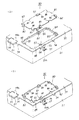
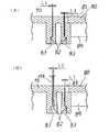
次に、本実施形態の要部を構成する基板収納ボックス50の構成について図1乃至図8を参照して説明する。図1は、実施形態に係る基板収納ボックス50の平面図であり、図2は、基板収納ボックス50の分解斜視図であり、図3は、基板収納ボックス50における被覆状態を現出する分離カバー体部80の拡大斜視図であり、図4は、基板収納ボックス50における被覆状態を解除する場合を説明する斜視図であり、図5は、図1のA−A線で切断した基板収納ボックス50の断面図と要部の拡大部分断面図であり、図6は、第2の固着手段としての係止片82を1つで構成した場合の係止片82と係合開口83との関係を示す拡大断面図であり、図7は、第2の固着手段としての係止片82を2つで構成した場合の係止片82と係合開口83との関係を示す拡大断面図であり、図8は、図1のB−B線で切断した基板収納ボックス50の断面図とその作用を説明するための断面図である。
【0019】
しかして、基板収納ボックス50は、遊技制御回路基板92を収納支持する箱体51と、該箱体51の上面を閉塞するカバー体70とが組付構成され、そのように組付構成された基板収納ボックス50は、前記機構板41の裏面に止着される取付台100に着脱自在に取り付け得るようになっている。以下、各組付構成部品毎に説明する。
【0020】
まず、箱体51は、上面が開放した直方体状に合成樹脂(金属でも良い)で形成され、その側壁のほぼ全域に内部で発生する熱を放熱するための放熱孔52が多数穿設されている。また、箱体51の底面には、比較的大きな長方形状の開口53が開設され、該開口53の長手方向開口縁には、取付台100の後述する係合レール101に係合するL字状の係合片54が垂下形成されている。なお、箱体51の底面は、図5(A)に示すように、側壁の下端よりもやや上方の位置に底上げ状態で形成されているため、垂下形成される上記係合片54は、箱体51の側壁と同一平面上に位置することとなる。
【0021】
更に、箱体51の底面には、その前方部中央に係止孔60が形成され、その一側長辺部左右に支持位置決め突起55が突設され、その他側長辺部左右に止め突起56が突設されている。係止孔60は、基板収納ボックス50を取付台100に装着した際に取付台100に形成される係止突起104と係合して基板収納ボックス50全体を機構板41の裏面に支持固定するものである。また、支持位置決め突起55は、遊技制御回路基板92の一側長辺部両端をカバー体70に設けられる後述する押え部材76と挟持して支持するものであり、止め突起56は、遊技制御回路基板92の他側長辺部両端をビス95で止着支持するものである。なお、支持位置決め突起55及び止め突起56については、後に詳述する。
【0022】
また、箱体51の長手方向一側側壁の2カ所及び短辺方向両側側壁の1カ所には、係合穴57が形成されている。この係合穴57は、カバー体70を箱体51に被覆したときにカバー体70の裏面に垂下形成される係止垂下片75と係合するようになっており、この係合穴57と係止垂下片75との係合状態は、通常時に、外部から操作してその係合状態を解除することができるようになっているが、本実施形態においては、箱体51の短辺側上縁中央に外側に向かって突設される溶着片61とカバー体70の後述する溶着片79とが溶着技術によって溶着されているので、係合穴57と係止垂下片75との係合状態を解除しても箱体51とカバー体70とを分離することはできないようになっている。なお、箱体51とカバー体70との組付けを分離できないような構造として溶着以外の構造(例えば、接着)であっても良い。また、溶着技術については、後に詳述する。
【0023】
更に、箱体51の長手方向の他側辺側壁は、高さが低く形成された配線引き出し凹部58となっており、また、箱体51の底面開口53の両側部には、複数の楕円形状の開口59が開設されている。開口59は、図5(A)に示すように、次に説明する透明板62によって閉塞されてしまうので、放熱孔としての機能を有さないが、箱体51を形成する原材料の軽減に寄与するものである。
【0024】
また、箱体51の前記開口53を閉塞するために透明板62が箱体51の内側から底面に当接して設けられる。このため、透明板62の四隅には、間隔保持筒部63が上面に形成され、この間隔保持筒部63が図5(A)に示すように、前記支持位置決め突起55及び止め突起56を貫通して所定の位置に保持され、また、間隔保持筒部63の上面に遊技制御回路基板92の下面が当接して透明板62と遊技制御回路基板92との間隔を保持している。しかして、箱体51の底面を透明板62で閉塞することにより、遊技制御回路基板92の裏面(ハンダ面)が外部から透視し得ることとなり、仮にハンダ面に不正な工作(例えば、ジャンパー配線を接続したり、電子部品を実装したりする不正工作)をした場合には、直ちにわかるようになっている。この意味で、透明板62によって閉塞される開口53の大きさは、基板収納ボックス50を傾けながらハンダ面の全域が見える程度の大きさがあれば十分である。
【0025】
一方、上記した箱体51の上面を閉塞するカバー体70は、透明な合成樹脂によって一体的に成形されるもので、その長手方向の他側辺部が下方向に曲折された仕切片71となっている。この仕切片71の位置は、カバー体70を箱体51に装着したときに図1に示すように、遊技制御回路基板92のコネクタ実装領域94が外部に現れて接続開口72を形成するような位置で曲折される。これにより、箱体51にカバー体70を組付構成した状態で接続開口72に臨むコネクタ99に外部からの配線を接続することができる。また、カバー体70の表面の後述する分離カバー体部80及び表示領域77a,77bを除く領域には、内部で発生した熱を外部に放出するための放熱孔73(図1の二点鎖線で囲んだ範囲)が多数形成されている。なお、表示領域77aには、基板収納ボックス50を取付台100から取り外す方法の説明が表示され、表示領域77bには、前述した溶着部分の破壊の方法の説明が表示されている。
【0026】
更に、カバー体70の長辺方向端縁及び短辺方向端縁には、箱体51の側壁上端縁と係合する掛止部74が適宜間隔を置いて2個ずつ突設され、該掛止部74の間のカバー体70には、下方に向かって垂下される係止垂下片75が形成されている。係止垂下片75には、先端に爪部75aが形成され、この爪部75aが箱体51の前記係合穴57に係合するようになっている。
【0027】
また、カバー体70の一側辺部両側に押え部材76が垂下されており、また、カバー体70を箱体51に組み付けた状態で、カバー体70の上面と箱体51の側壁との間を差し渡すように封印紙78が貼付される。更に、箱体51の前記溶着片61に対応する位置に溶着片79が外側に向かって突設されている。この溶着片79の基部には、切込溝79aが形成されており、この切込溝79aと溶着片61の基部裏面に形成される折曲凹部61aとにより、溶着部分を容易に破壊できるようにしている。この点については、後に詳述する。
【0028】
上記した押え部材76の詳細な説明をする前に、遊技制御回路基板92の構造について簡単に説明すると、遊技制御回路基板92は、周知のようにプリント配線基板によって構成され、その上面がROM98を含む電子部品の実装面とされ、その実装面の大部分が電子部品実装領域93として使用され、後方の一部がコネクタ99が実装されるコネクタ実装領域94とされる。また、遊技制御回路基板92には、その一側長辺左右に前記支持位置決め突起55に対応する係止穴96が形成され、その他側長辺左右に前記止め突起56に対応する止め穴97が形成されている。
【0029】
上記のように構成されるカバー体70の押え部材76の作用について以下説明する。透明板62が装着された状態の箱体51において、遊技制御回路基板92の一側長辺の係止穴96を支持位置決め突起55の先端突起部に差し込み、他側長辺の止め穴97を止め突起56に載置する。この状態で止め穴97と止め突起56の穴を一致させてビス95を螺着することにより、一応、遊技制御回路基板92を箱体51に止着したこととなる。そして、その後、カバー体70を箱体51の上方から装着する。この際、押え部材76の先端部が図5(A)に示すように、遊技制御回路基板92の上面に当接すると共に、係止穴96を貫通している支持位置決め突起55の先端突起部が押え部材76の中心に形成された穴に係合するので、遊技制御回路基板92の一側長辺部が支持位置決め突起55と押え部材76とによって挟持止着された状態となり、他側長辺部のビス95による止着とで完全に遊技制御回路基板92を基板収納ボックス50内に止着したこととなる。
【0030】
ところで、カバー体70には、本実施形態の要部を構成する分離カバー体部80が形成されている。この分離カバー体部80の構成について主として図3乃至図6を参照しながら以下詳細に説明する。分離カバー体部80は、長方形状であって遊技制御回路基板92に実装されるROM98の上方部分の対応する位置に設けられ、その長手方向の適宜箇所に2個ずつブリッジ状に掛け渡される連結突部81によってカバー体70と分離カバー体部80とが一体的に形成(本実施形態では、合成樹脂による一体成形)されている。そして、連結突部81を、例えばニッパ等の工具を用いて切断することにより、分離カバー体部80をカバー体70から完全に分離することができるようになっている。
【0031】
また、分離カバー体部80の四辺の各辺には、先端に爪部を有する係止片82が上方向に向かって突設されている。この係止片82は、サンプル検査時等に前記連結突部81を切断して分離カバー体部80を分離してROM98を検査した後に、再度分離カバー体部80を裏返してカバー体70に装着する際に使用するものである。しかして、本実施形態における係止片82は、背中合わせに一対の突片として形成され、先端の爪部が互いに外向きとなっている。もちろん、外側(分離カバー体部80の端縁に沿った側)の係止片82の1つだけでもよいが、後述するように1つの係止片82だけでは、その係止片82を破壊しなくても係合状態を解除することができる可能性があるので、好適な例とは言えない。なお、内側の係止片82の基部には、その係止片82を合成樹脂で一体成形するための爪形成用開口85が形成されている。
【0032】
また、連結突部81を切断して分離カバー体部80を分離したときには、カバー体70に長方形状の分離開口縁84が形成されることとなるが、この分離開口縁84の適宜箇所には、分離カバー体部80を裏返して装着したときに、前記係止片82と係合する係合開口83が形成され、その係合開口83に対応する分離カバー体部80には、係合開口83を合成樹脂で一体成形するための係合開口形成用切欠86が形成されている。また、分離カバー体部80を裏返して装着する際に、その装着方向が容易に理解できるように、分離カバー体部80に位置合せ凹部87が、カバー体70に位置合せ凸部88がそれぞれ一側に形成されている。更に、カバー体70の分離開口縁84に沿って補強用の内部リブ89が下方に向かって突設されており、この内部リブ89を利用して前記係合開口83が形成されている。また、分離カバー体部80の表面には、連結突部81を切断する方法についての説明書が形成されている表示領域90、及び切断箇所を指し示す切断箇所表示部91が形成されている。
【0033】
なお、図示しないが、分離カバー体部80とカバー体70とが連結突部81によって連結された初期の連結状態において、カバー体70の内側面に分離カバー体部80とカバー体70との間に掛け渡されるように予め内側封印シールを貼付しても良い。このように内側封印シールを貼付することにより、分離カバー体部80を分離した後に、再度係止片82と係合開口83とによって被覆状態を復元してもその内側封印シールの貼付状態を復元することはできないので、少なくとも分離カバー体部80が一度は、被覆状態が解除されたことが理解できるものである。
【0034】
上記のように構成される基板収納ボックス50においては、箱体51とカバー体70とが溶着片61,79によって強固に溶着されているので、箱体51とカバー体70とを分離して遊技制御回路基板92の被覆状態を解除することは不可能である。しかして、その被覆状態を解除しようと思えば、連結突部81をニッパ等の工具で切断して分離カバー体部80をカバー体70から分離させてROM98を臨ませなければならない。しかしながら、このように連結突部81を切断したときには、その切断したことにより、連結突部81が無くなるので、その点からだけでも遊技制御回路基板92のROM98に不正な処理を施したか否かがわかる。
【0035】
なお、遊技場においては、監督官庁によりパチンコ島台に列設されるパチンコ遊技機1の中から1台又は2台程度抜き出してROM98の検査(サンプル抽出検査)を行う場合がある。このようなサンプル抽出検査を行う場合には、図4(A)及び図5(B)に示すように、連結突部81をニッパ等で切断して分離カバー体部80を分離せしめてROM98を露出せしめ、そのROM98を引き抜いて調査した後、再度ROM98を遊技制御回路基板92に実装し、その後、図4(B)及び図5(C)に示すように、分離カバー体部80を裏返して係止片82を係合開口83に係合させて分離カバー体部80をカバー体70に装着する。
【0036】
この装着構造についてより詳細に説明すると、図6に示すように、1つの係止片82を係合開口83の係合部に係合させる場合には、カバー体70と分離カバー体80との隙間から不正ピン105を差し込んで係止片82を弾性変形させることにより、係止片82と係合開口83の係合部との係合状態を解除させ、その状態で図6(B)に示すように、分離カバー体部80を引き出すことにより、係止片82部分を破壊することなく被覆状態を解除することができる可能性がある。これに対し、本実施形態のように、係止片82が背中合わせの一対の突片から構成されている場合には、図7(A)に示すように、カバー体70と分離カバー体部80との間に微小な隙間L1が左右にあったとしても、図7(B)に示すように一方の隙間L1から不正ピン105を差し込んで隙間の間隔をL2に広げて係合状態を解除しても、他方の隙間L1は、限りなく0に近い隙間L3となって不正ピン105を挿入することができなくなるので、他方の係止片82と係合開口83との係合状態を解除することができず、結局、左右の係止片82の係合状態を同時に解除することができないので、係止片82と係合開口83とに基づく被覆状態を解除することは、ほとんど不可能であり、この被覆状態を解除するためには、少なくとも係止片82を破壊しなければならず、係止片82を破壊したときには、その痕跡が残り、その痕跡に基づいて遊技制御回路基板92のROM98に不正な処理を施したか否かがわかる。
【0037】
なお、上記した実施形態では、分離カバー体部80を分離後、裏返して固着しているが、これに限らず、分離カバー体部80の内側面に係止部82を形成し、分離後裏返すことなく180度回転し固着するようにしてもよい。この場合、当初から係止片82は外側に突出していないため、不可抗力により係止片82をひっかけて破損するようなことがないという利点がある。
【0038】
ところで、上記のように分離カバー体部80を裏返して装着した状態で遊技制御回路基板92は、再度被覆された状態となり、この被覆状態を保証するために、検査を行った監督官庁が発行する検査済封印紙(図示しない)を分離カバー体部80とカバー体70との間を掛け渡すように貼付すれば良い。
【0039】
なお、本実施形態においては、1回目の検査を上記したカバー体70と分離カバー体部80とを分離して行った後に再度検査する必要が生じる場合も考慮して、カバー体70と箱体51とを破壊することにより分離できる構成を採用している。即ち、図8に示すように、箱体51とカバー体70との溶着片61,79による溶着部分をラジオペンチ等の工具で挟んで折り曲げることにより、その溶着部分が折曲凹部61aと切込溝79aとによって簡単に折曲でき、その後、図8(B)に示すように、係合穴57にドライバ工具106等を差し込んで係止垂下片75の爪部75aを係合穴57から外してカバー体70を持ち上げれば、カバー体70による箱体51の被覆状態を解除することができる。その解除した状態でROM98の検査が終了した後は、再度カバー体70を箱体51に被覆して係止垂下片75の爪部75aを係合穴57に係合させることにより、被覆状態を復元することができる。ただし、この場合には、簡単に係止垂下片75と係合穴57との係合状態を解除することができるので、被覆状態を保証するために、検査を行った監督官庁が発行する検査済封印紙(図示しない)を箱体51とカバー体70との間を掛け渡すように貼付する必要がある。
【0040】
また、上記した実施形態では、第1の固着手段及び第2の固着手段により分離カバー体部80においてROM98等の検査を1回のみ行えるようになっているものを示したが、これに限らず、第3、第4、・・・第N固着手段を分離カバー体部80に設け、複数回の検査が行われても固着できるようにしてもよい。
【0041】
また、上記した実施形態では、第1、第2の固着手段は分離カバー体部80について実施しているが、これに限らず、前記箱体51とカバー体70について同様の固着手段を適用してもよい。
【0042】
以上、本実施形態に係る基板収納ボックス50の構成及び作用について説明してきたが、本実施形態においては、パチンコ遊技機1に設けられる遊技制御回路基板92を収納する基板収納ボックス50において、該基板収納ボックス50が前記遊技制御回路基板92を収納する箱体51、該箱体51の底面開口53を閉塞する透明板62、箱体51の上面を被覆するカバー体70等の複数の構成部品によって組み付け構成されると共に、遊技制御回路基板92を被覆するための組付構成部品である箱体51とカバー体70のうち、カバー体70の一部を構成する分離カバー体部80の連結突部81を切断して破壊しない限りその被覆状態を解除することができない第1の固着手段としての連結突部81と、該連結突部81による被覆状態を解除した後に再度遊技制御回路基板92の被覆状態を復元し且つそれ自体を破壊しない限りその被覆状態を解除することができない第2の固着手段としての係止片82及び係合開口83と、を設けたので、箱体51とカバー体70による遊技制御回路基板92の被覆状態を検査等のために解除するには、分離カバー体部80の連結突部81を切断破壊して分離カバー体部80をカバー体70から分離し、分離カバー体部80の下方に配置されるROM98等を検査した後、再度、分離カバー体部80を裏返して係止片82をカバー体70側に形成される係合開口83に差し込むことにより、被覆状態を復元することができ、しかも、その復元された被覆状態を解除するためには、再度係止片82部分を破壊する以外に方法はなく、仮に係止片82部分が破壊されていれば、不正な処理が行われたことが直ちにわかる。
【0043】
また、本実施形態では、連結突部81の切断による被覆状態を解除したときに遊技制御回路基板92が包含される組付構成部品側であるカバー体70に複数個の係合開口83を形成し、分離される組付構成部品側である分離カバー体部80に形成され且つ係合開口83のそれぞれに対して左右の2カ所で係合する係止片82を形成することにより、一方の係止片82を外すために不正ピン105を挿入しても他方の係止片82側に不正ピン105を挿入することができず、結局2つの係止片82を同時に外すことはほとんど不可能であり、係止片82と係合開口83とに基づく再被覆状態をより強固に行うことができる。
【0044】
上記のように外部からは分離できないように組付構成された基板収納ボックス50は、図2に示すような機構板41に止着される取付台100に着脱自在に取り付けられるようになっている。ここで簡単に取付台100の構成について説明すると、取付台100は、合成樹脂(金属でも良い)によって一体的に形成され、その中央に前記係合片54と係合する一対の係合レール101が逆L字状に形成され、その上下端縁に基板収納ボックス50の側壁を案内するガイド片102(このガイド片102は必ずしも必要でない)が突設されている。一方、取付台100の一側端部には、弾性変形する係止解除レバー103が形成され、該係止解除レバー103の基部に前記係止孔60と係合する係止突起104が突設されている。
【0045】
しかして、基板収納ボックス50を取付台100に装着するときには、取付台100の側方から係合片54が係合レール101に係合するように押し込み、更に強く押し込むことにより係止突起104上面の傾斜面に沿って係止解除レバー103が下方に弾性変形し、遂には、係止突起104と係止孔60とが係合して装着を完了する。一方、基板収納ボックス50を取り外すには、係止解除レバー103を下方に押圧して係止孔60と係止突起104との係合を解除した状態で基板収納ボックス50を押し込み方向とは逆の方向に引き抜くことにより簡単に取り外すことができる。
【0046】
ところで、上記した実施形態においては、箱体51とカバー体70とを溶着片61,79を溶着して分離できないような構成について説明したが、この溶着技術は、図12に示す溶着装置を利用して行われる。図12は、超音波プラスチック溶着装置の原理を示す概略図である。図において、ベース120に受治具121が載置され、その受治具121に溶着物122を乗せ、一方、溶着物122の上部には、ホーン123が位置し、このホーン123に超音波振動を付与する超音波振動子124を連結すると共に、ホーン123に圧力を加えるシリンダ125を連結する。超音波振動子124には、制御部によって制御される超音波発振器が接続され、シリンダ125は、空圧制御回路によって制御される。しかして、ベース120に設けられる起動スイッチ126を操作して装置を稼働させたときには、ホーン123に超音波振動が発生すると共に、ホーン123に所定の圧力を加えて溶着物122を加圧する。そして、その加圧状態で溶着物122の境界面に摩擦熱が発生して、その摩擦熱によって境界面が瞬時に溶着する。なお、ベース120には、非常時に装置の稼働を停止する非常スイッチ127が設けられている。
【0047】
そして、上記した溶着装置を用いて2つの突片を実際に溶着する場合について図9乃至図11を参照して説明する。図9乃至図11は、箱体51とカバー体70とを実際に溶着する際の各種の構造を示す概略断面図である。図9乃至図11に示す溶着構造においては、箱体51の上辺の適宜箇所から水平方向に延びる溶着突片110を延設し、一方これに対応するカバー体70にも水平方向に溶着突片111を延設し、箱体51にカバー体70を合わせたときに、相互の溶着突片110,111が当接した状態となり、その当接部分を超音波プラスチック溶着装置によって溶着するものである。なお、溶着突片110,111の基部には、切れ込み部110a,111aが形成されており、検査時等に容易に溶着部分を折曲分離することができるようになっている。
【0048】
しかして、溶着するに際し、図9に示すように、カバー体70の溶着突片111の下面に円錐状の突起111bを形成しておくことにより、溶着時間を極めて短くすることができると共に、溶解した突起111bが境界面を埋める埋め代となって十分な溶着強度を得ることができる。また、図10に示すように、溶着突片111の下面に円柱状の突起111cを形成し、溶着突片110に突起111cの径より若干小さい径の嵌入穴110bを形成し、これらを加圧しながら溶着することにより、突起111cが嵌入穴110bに嵌入溶着されて上記と同様に十分な溶着強度を得ることができる。同じく、十分な溶着強度を得るために溶着突片110,111側に工夫を凝らすのではなく、装置のホーン123の先端形状を図11に示すように、波形突起123aとすることにより、溶着後の溶着部分に溶着凹部113を形成することができ、この溶着凹部113によっても十分な溶着強度を得ることができる。
【0049】
上記のような動作原理の溶着装置を用いて溶着突片110,111を溶着することにより、箱体51とカバー体70とが、その溶着部分を破壊しない限り、分離することは不可能となる。このため、箱体51とカバー体70を分離して内部に収納される遊技制御回路基板92を取り出すには、少なくとも溶着部分の切れ込み部110a,111aを折曲分離する以外に方法はなく、仮に溶着部分が折曲分離されていれば、不正な処理が行われたことが直ちにわかる。
【0050】
次に、同じく溶着技術を用いて固着する他の固着構造に係る基板収納ボックス50の構成について図13乃至図16を参照して説明する。図13は、他の溶着構造を利用して箱体51とカバー体70とを固着した基板収納ボックス50の平面図であり、図14は、溶着部分の部分平面図と断面図であり、図15及び図16は、類似の溶着構造を示す断面図である。なお、この基板収納ボックス50のカバー体70には、分離カバー体部80が描かれていないが、これは図示が省略されたものである。
【0051】
しかして、基板収納ボックス50は、カバー体70の外周縁の適宜位置(図示では、3カ所)に長方形状の貫通穴130を形成すると共に、その貫通穴130に向かって傾斜する傾斜面部131を周設し、更に、貫通穴130の裏面一側にガイド片134を周設し、一方、箱体51には、貫通穴130を貫通する断面長方形状の突出片132を突設したものである。そして、突出片132をガイド片134に沿って貫通穴130に貫通した状態で図14(C)に示すように、溶着装置のホーン123で突出片132の頭部を溶解してその溶着部133が傾斜面部131と溶着係合することによって、箱体51とカバー体70とが、その溶着部133を破壊しない限り、分離することは不可能となる。このため、箱体51とカバー体70を分離して内部に収納される遊技制御回路基板92を取り出すには、少なくとも溶着部133を破壊する以外に方法はなく、仮に溶着部133が破壊されていれば、不正な処理が行われたことが直ちにわかる。
【0052】
なお、この溶着構造においては、溶着部133の基部(即ち、突出片132の基部)をきれいに切断して箱体51とカバー体70とを分離して不正行為を行った後その切断面に接着剤を塗布して再度箱体51とカバー体70とを組み付けるという不正を行われる可能性があるので、図14(E)に示すように、貫通穴130の裏面の他側にも防犯用のガイド片135を突設すれば、上記のような不正行為を防止することができる。
【0053】
また、突出片132や貫通穴130の形状を変えたりしても良い。例えば、図15に示すように、カバー体70に貫通穴を形成せず、箱体51の突出片136をクランク状に形成してカバー体70を受けるように構成し、そのクランク状突出片136の先端を先端形状が半円状のホーン123によって内側に溶着して溶着部137でカバー体70を包み込むように構成しても良い。また、図16に示すように、カバー体70の貫通穴130の周辺部に傾斜面部を形成することなく突出片132を突出した場合には、ホーン123の形状を富士額状に形成して、突出片132の先端を二股状に分けてカバー体70の上面を被覆溶着する溶着部138としても良い。
【0054】
更に、箱体51とカバー体70との分離できない構造として上記した溶着技術以外に、例えば、図17、図18及び図19、図20及び図21に示す各構成を採用しても良い。最初に図17に示される構成について説明する。図17は、箱体51とカバー体70との固着をリベットで行う場合の断面図である。図において、カバー体70に形成された貫通穴を貫通して一旦上方に突出された後U字状に曲折されてカバー体70の上面と一体的に接続され且つ先端に爪部を有する係止垂下片140をカバー体70に形成し、一方、その上面が傾斜面となっており、その下部が鋭角的に切り込まれた係合面となっている係止突起141を箱体51に一体的に形成し、カバー体70を箱体51の上方から装着すると、係止垂下片140の爪部が係止突起141の係合面と係合した状態となり、この係合状態を解除できないようにするため、係止突起141と係止垂下片140とをリベット142で固着するようになっている。
【0055】
ここで、係止突起141と係止垂下片140とをリベット142で固着する方法について説明すると、本実施形態に用いられるリベット142は、ブラインドリベット142と言われるもので、アルミニューム製のリベット142本体の中に、一端部にリベット142の内周筒を挿通し得ない係合部143aを有し且つ係合部143aの基部に径の細い折曲部143bを有する引きピン143を挿入したものである。そして、係止突起141と係止垂下片140との合致した貫通穴にブラインドリベット142を差し込み、その状態で所定の工具を使用して引きピン143を図17(A)に示す矢印方向に引くと、係合部143aによってリベット142の足部が図17(B)に示すように変形し、リベット142の頭部と変形した端部とによって完全に係止突起141と係止垂下片140とが挟持された状態となり、その後、引きピン143をさらに強く引っ張ることにより、折曲部143bから折れて先端部が分離する。
【0056】
このような状態において、基板収納ボックス50の外側からリベット142の挟持状態を解除する操作を行うことは不可能であるため、一旦カバー体70を箱体51に装着してリベット142を固着した後には、簡単にカバー体70を箱体51から外すことはできない。しかして、これを外そうと思えば、係止垂下片140の基部140aを図17のC−C線に沿ってニッパ等で切断して係止垂下片140をカバー体70から分離させなければならないので、係止垂下片140の基部140aが破損されていれば、不正な行為が行われたことが直ちに理解できるものである。
【0057】
次に、箱体51とカバー体70とのさらに他の固着手段について説明する。図18及び図19は、最も手軽に行える固着手段の形態を示すものである。図18は、基板収納ボックス50の断面図であり、図19は、要部の拡大部分断面図である。図において、箱体51の内側側面に係止ひも150を一体的に形成し、この係止ひも150をカバー体70に形成される貫通穴152を通して外部に引き出し、その引き出した係止ひも150の先端部分に形成されるのこぎり状係止部151を箱体51の外側側面に形成される係止穴内を貫通させて該係止穴内に形成される係止部153に係止させ、係止穴から突出した部分を切断する。このように構成することにより、一旦係止ひも150を貫通穴152に貫通させた後には、のこぎり状係止部151と係止部153との係合状態は、通常の状態のままでは、はずしにくく、強制的にはずした場合には、係止ひも150に傷が付いていたりして容易に不正をはたらいたか否かがわかる。したがって、係止ひも150を傷つけないで係止ひも150を引き抜くことは不可能に近く、結局、箱体51とカバー体70を分離して内部に収納される遊技制御回路基板92を取り出すには、少なくとも係止ひも150を切断する以外に方法はなく、仮に係止ひも150が切断されていれば、不正な処理が行われたことが直ちにわかる。
【0058】
更に、箱体51とカバー体70との固着手段について図20及び図21を参照して説明する。図20は、基板収納ボックス50の断面図であり、図21は、要部の部分拡大断面図である。図において、箱体51とカバー体70との装着は、図2に示すものと同じように、箱体51の側面に開設される係合穴57にカバー体70から垂下される係止垂下片75の爪部75aを係合させることにより行い、更に、係合穴57に対して箱体51の外側側面から該係合穴57を完全に塞ぐ平板部の前面に矢印状の係合部161が突設されたロック部材160を差し込んで係合部161によって爪部75aの裏面を係止するように構成したものである。つまり、箱体51とカバー体70との係合を係合穴57と係止垂下片75とで行い、その係合状態をロック部材160の係合部161で係止した構造である。この構造は、ロック部材160を係合穴57に差し込む際には、係合部161の圧入より爪部75aが若干後方に下がりながら受け入れるが、逆に、例えば放熱孔52からピアノ線等を差し込んで係合部161の係合をはずし、さらに係止垂下片75の爪部75aをはずすことは、ほぼ不可能であるし、実際にこれをやろうとすると、ロック部材160の係合部161の後ろの部分で破損してしまうものである。
【0059】
したがって、基板収納ボックス50を分離しようとすれば、図21(B)に示すように、ドライバ工具106等でロック部材160を破損しなければならず、仮にロック部材160が破損されていれば、不正な処理が行われたことが直ちにわかる。ただし、ロック部材160を破損させて、ロック部材160のコピー品を作成して元の状態に戻すという不正が行われる可能性もあるが、このような不正に対しては、例えば、ロック部材160の材質を複数種類のプラスチックを特定の割合で混ぜたものから成形することにより、成分分析することにより本物かコピー品であるかが分かるようにしておけば良い。この場合、外観からその成分比率を予測させないようにロック部材160にメッキ処理を施すことにより、予測させないと共に、コピーにかかる時間や経費を増大させ、結果的に不正がしづらくなるようにすることが望ましい。また、出荷時期や機種等によって混合比率を変化させることにより、一層コピーしづらくなるようにしても良い。なお、ロック部材160の材質は、プラスチックに限るものではなく、金属又は他の物質の混合物でも良い。なお、図13乃至図21に示す実施形態においては、箱体51とカバー体70とを固着する例として示したが、これを前記分離カバー体部80の固着手段として適用してもよい。
【0060】
以上、本発明に係る実施形態について説明してきたが、本実施形態においては、パチンコ遊技機1に設けられる遊技制御回路基板92を収納する基板収納ボックス50において、該基板収納ボックス50が前記遊技制御回路基板92を収納する箱体51、該箱体51の底面開口53を閉塞する透明板62、箱体51の上面を被覆するカバー体70等の複数の構成部品によって組み付け構成されると共に、遊技制御回路基板92を被覆するための組付構成部品である箱体51とカバー体70のうち、カバー体70の一部を構成する分離カバー体部80の連結突部81を切断して破壊しない限りその被覆状態を解除することができない第1の固着手段としての連結突部81と、該連結突部81による被覆状態を解除した後に再度遊技制御回路基板92の被覆状態を復元し且つそれ自体を破壊しない限りその被覆状態を解除することができない第2の固着手段としての係止片82及び係合開口83と、を設けたので、箱体51とカバー体70による遊技制御回路基板92の被覆状態を検査等のために解除するには、分離カバー体部80の連結突部81を切断破壊して分離カバー体部80をカバー体70から分離し、分離カバー体部80の下方に配置されるROM98等を検査した後、再度、分離カバー体部80を裏返して係止片82をカバー体70側に形成される係合開口83に差し込むことにより、被覆状態を復元することができ、しかも、その復元された被覆状態を解除するためには、再度係止片82部分を破壊する以外に方法はなく、仮に係止片82部分が破壊されていれば、不正な処理が行われたことが直ちにわかる。
【0061】
また、本実施形態では、連結突部81の切断による被覆状態を解除したときに遊技制御回路基板92が包含される組付構成部品側であるカバー体70に複数個の係合開口83を形成し、分離される組付構成部品側である分離カバー体部80に形成され且つ係合開口83のそれぞれに対して左右の2カ所で係合する係止片82を形成することにより、一方の係止片82を外すために不正ピン105を挿入しても他方の係止片82側に不正ピン105を挿入することができず、結局2つの係止片82を同時に外すことはほとんど不可能であり、係止片82と係合開口83とに基づく再被覆状態をより強固に行うことができる。
【0062】
また、上記した実施形態では、基板収納ボックス50の組付構成部品として、箱体51とカバー体70と遊技制御回路基板92とからなるものを示したが、遊技制御回路基板92を収納するものであれば、どのような構造のものでも良い。この場合、上記した実施形態では、カバー体70による箱体51の被覆構造がコネクタ実装領域94を露出した状態としているが、本実施形態を含めてカバー体70による被覆状態をコネクタ実装領域94まで拡大して、簡単にコネクタの脱着を行えないようにしても良い。また、基板収納ボックス50に収納される基板も遊技動作を制御するものに限らず、不正行為が行われ易い回路基板(例えば、景品玉の払出動作を制御する景品玉払出制御回路基板、表示器用の表示制御回路基板、発射動作を制御する発射制御回路基板、配線を中継する中継端子回路基板、電源端子や信号端子が設けられるターミナル回路基板等)を収納する基板収納ボックスにも応用することができる。更に、遊技機としては、パチンコ遊技機以外の遊技機であっても良い。
【0063】
【発明の効果】
以上、説明したところから明らかなように、本発明においては、遊技機に設けられる回路基板を収納する基板収納ボックスにおいて、該基板収納ボックスが前記回路基板を被覆するように複数の構成部品によって組み付け構成され、該組み付け構成される構成部品に係る所定の部位を破壊しない限り前記回路基板の被覆状態を解除することができない第1の固着手段と、該第1の固着手段による被覆状態を解除した後に再度前記回路基板の被覆状態を復元し且つ前記組み付け構成される構成部品に係る前記所定の部位と異なる部位を破壊しない限り再度の前記回路基板の被覆状態を解除することができない第2の固着手段と、を設け、前記第2の固着手段は、係合部と、前記係合部に対して係合する係止片と、により構成されるので、回路基板の被覆状態を検査等のために解除するには、第1の固着手段を破壊して被覆状態を解除し、所定の検査をした後、再度、第2の固着手段の係合部と係合片とによって被覆状態を復元することができ、しかも、その復元された被覆状態を解除するためには、再度第2の固着手段を破壊する以外に方法はなく、仮に第2の固着手段部分が破壊されていれば、不正な処理が行われたことが直ちにわかる。
【0064】
【図面の簡単な説明】
【図1】 実施形態に係る基板収納ボックスの平面図である。
【図2】 基板収納ボックスの分解斜視図である。
【図3】 基板収納ボックスにおける被覆状態を現出する分離カバー体部の拡大斜視図である。
【図4】 基板収納ボックスにおける被覆状態を解除する場合を説明する斜視図である。
【図5】 図1のA−A線で切断した基板収納ボックスの断面図と要部の拡大部分断面図である。
【図6】 第2の固着手段としての係止片を1つで構成した場合の係止片と係合開口との関係を示す拡大断面図である。
【図7】 第2の固着手段としての係止片を2つで構成した場合の係止片と係合開口との関係を示す拡大断面図である。
【図8】 図1のB−B線で切断した基板収納ボックスの断面図とその作用を説明するための断面図である。
【図9】 箱体とカバー体とを実際に溶着する際の各種の構造を示す概略断面図である。
【図10】 同じく箱体とカバー体とを実際に溶着する際の各種の構造を示す概略断面図である。
【図11】 同じく箱体とカバー体とを実際に溶着する際の各種の構造を示す概略断面図である。
【図12】 超音波プラスチック溶着装置の原理を示す概略図である。
【図13】 他の溶着構造を利用して箱体とカバー体とを固着した基板収納ボックスの平面図である。
【図14】 図13の基板収納ボックスの溶着部分の部分平面図と断面図である。
【図15】 図13の溶着構造の類似の溶着構造を示す断面図である。
【図16】 同じく図13の溶着構造の類似の溶着構造を示す断面図である。
【図17】 箱体とカバー体との固着をリベットで行う場合の断面図である。
【図18】 箱体とカバー体との固着を係止ひもで行う場合の基板収納ボックスの断面図である。
【図19】 その要部の部分拡大断面図である。
【図20】 箱体とカバー体との固着をロック部材で行う場合の基板収納ボックスの断面図である。
【図21】 その要部の部分拡大断面図である。
【図22】 実施形態に係る遊技機の一例としてのパチンコ遊技機の正面図である。
【図23】 パチンコ遊技機の背面図である。
【符号の説明】
1 パチンコ遊技機(遊技機)
50 基板収納ボックス
51 箱体
57 係合穴
70 カバー体
75 係止垂下片
75a 爪部
78 封印紙
80 分離カバー体部
81 連結突部(第1の固着手段)
82 係止片(第2の固着手段)
83 係合開口(第2の固着手段;係合部)
92 遊技制御回路基板(回路基板)
98 ROM
100 取付台[0001]
BACKGROUND OF THE INVENTION
The present invention relates to a board storage box for storing a circuit board provided in a gaming machine, for example, a pachinko gaming machine or a slot machine.
[0002]
[Prior art]
Conventionally, many circuit boards are provided in pachinko gaming machines and slot machines. In particular, a lot of electronic elements such as MPU, ROM, and RAM constituting a microcomputer are mounted on a game control circuit board that controls game operations. In many cases, it is possible to realize different game contents by exchanging the ROM storing the program for controlling the game operation. However, such ROM exchange is not permitted because it is different from the originally approved game content, and in order to prevent this, the applicant has previously disclosed in JP-A-6-269539. Proposed technology.
[0003]
In the above-described technique, the locking hanging piece 66 suspended from the cover body 60 covering the box body 51 is engaged with the locking protrusion 57 protruding from the inner peripheral surface of the box body 51 of the substrate storage box 50. Once the engagement protrusion 57 and the engagement suspension piece 66 are engaged, the engagement state cannot be removed from the outside unless the base of the engagement suspension piece 66 is cut. It was.
[0004]
[Problems to be solved by the invention]
However, once the base portion of the locking drooping piece 66 is cut, the cover body 60 cannot be locked again to the box body 51. For example, the base portion of the locking drooping piece 66 is inspected by a supervisory authority or the like. After cutting, there was a disadvantage that the coated state could not be restored again. The present invention has been made in view of the above-described circumstances, and the object of the present invention is to restore the covering state again even after the covering state is once released, and to accommodate the inside after the restoration. An object of the present invention is to provide a board storage box for a gaming machine that cannot perform illegal processing on a circuit board.
[0005]
[Means for Solving the Problems]
In order to achieve the above object, the means adopted by the present invention will be described with reference to the drawings. As shown in FIGS. 3 to 5, in a board storage box 50 for storing a circuit board 92 provided in a gaming machine. The board storage box 50 holds the circuit board 92. To coat It is assembled and configured by a plurality of components such as a box 51, a transparent plate 61 that closes the bottom opening 53 of the box 51, and a cover 70 that covers the top surface of the box 51. This breaks the connecting projection 81 related to the assembled component. Unless it breaks Circuit board 92 A connecting projection 81 as a first fixing means that cannot be released from the covering state, and the covering state of the circuit board 92 is restored again after the covering state by the connecting protrusion 81 is released, and A locking piece 82 which is a part different from the connecting projection 81 related to the assembled component. Unless you destroy Circuit board 92 again Second fixing means that cannot release the covering state of The second fixing means includes an engaging opening 83 and a locking piece 82 that engages with the engaging opening 83. It is characterized by this.
[0006]
With this configuration, in order to release the covering state of the circuit board 92 by the box body 51 and the cover body 70 for inspection or the like, the connection projection 81 of the separation cover body portion 80 is cut and broken to separate the separation cover. After separating the body part 80 from the cover body 70 and inspecting the ROM 98 and the like disposed below the separation cover body part 80, the separation cover body part 80 is turned over again to form the locking piece 82 on the cover body 70 side. The covering state can be restored by inserting it into the engagement opening 83, and there is no method other than destroying the locking piece 82 part again in order to release the restored covering state, If the locking piece 82 portion is broken, it is immediately known that an unauthorized process has been performed.
[0007]
[0008]
DETAILED DESCRIPTION OF THE INVENTION
Embodiments of the present invention will be described below with reference to the drawings. First, with reference to FIG.22 and FIG.23, the structure of the pachinko gaming machine 1 as an example of the gaming machine according to the embodiment will be described. FIG. 22 is a front view of the pachinko gaming machine 1, and FIG. 23 is a rear view of the pachinko gaming machine 1. In FIG. 22, a door holding frame 3 is provided around the opening of the front frame 2 formed in a frame shape of the pachinko gaming machine 1, and the glass door frame 4 and the front door plate 5 are connected to the door holding frame 3. It can be opened and closed with the side (left side) as an axis. A game board 11 is disposed behind the glass door frame 4, and a hitting ball supply tray 6 is attached to the front surface of the front door plate 5. The hitting ball supply tray 6 stores the paid out prize balls and supplies them one by one to the launch position as hitting balls. The speaker 7 generates sound effects related to the game in the internal space on the upstream side. Is built-in. Further, below the front frame 2, there are provided an operation handle 9 that is operated when firing a hit ball, and an extra ball receiving tray 8 that stores an extra prize ball that cannot be stored in the hit ball supply tray 6. ing. Further, the front frame 2 is provided with a game effect lamp device 10 for notifying that a specific game state has been reached on the upper front surface thereof.
[0009]
By the way, on the surface of the game board 11, a guide rail 12 for guiding the shot hit ball is planted in a substantially circular shape, and an area partitioned by the guide rail 12 constitutes a game area 13. Yes. A variable display device 14 having a plurality of (three) rotating drums 15a to 15c is disposed substantially at the upper center of the game area 13. The rotary drums 15a to 15c of the variable display device 14 are rotationally driven by an independent drum motor (not shown), and a drum sensor (not shown) is built in to detect the symbol stop position, and further displayed symbols. It incorporates a drum lamp (not shown) for decorating the lamp.
[0010]
Further, the variable display device 14 is provided with a decoration LED 20 at an upper portion thereof, and a start memory LED 21 is provided at a lower portion of the decoration LED 20. The decoration LED 20 is composed of 10 LEDs with signs from 0 to 9, and the LED corresponding to a value extracted from a predetermined random number is turned on when a specific gaming state described later is entered. ing. The decoration LED 20 is randomly lit and displayed in association with the occurrence of the specific game state, and is not directly related to the game content, but the game hall is in a predetermined service (for example, in the specific game state). This service can be used to provide a service that allows a player to continue playing using a large amount of free gift balls. For example, a predetermined service may be provided when the lighting of the decoration LED 20 “7” is stopped. Further, the start memory LED 21 displays the memorized ball among the hitting balls won in the start winning opening 23 described later. Further, on both sides of the variable display device 14, there are provided line display LEDs 22 for displaying five hit lines composed of three vertical and horizontal symbols of the rotating drums 15a to 15c. In the present embodiment, as shown in the figure, the upper horizontal hit line 1, the lower right diagonal hit line 2, the interrupted horizontal hit line 3, the upper right diagonal hit line 4, and the lower horizontal hit line are shown. There is a hit line 5, and when a predetermined symbol (sometimes referred to as a big hit symbol) is arranged on any of the hit lines, it becomes a big hit and a specific gaming state is caused.
[0011]
Below the variable display device 14 configured as described above, a start winning opening 23 that allows rotation of the rotating drums 15a to 15c is provided. The winning ball won in the start winning opening 23 is guided to the back surface of the game board 11 and detected by the start opening switch 24. Note that the rotation of the variable display device 14 based on winning in the start winning opening 23 is stored a predetermined number of times (for example, four times), and this is displayed by the start memory LED 21 provided in the variable display device 14. ing.
[0012]
A variable winning ball device 25 having a winning area 26 is provided below the variable display device 14. The winning area 26 of the variable winning ball apparatus 25 is closed by an opening / closing plate 27 that pivotally supports both lower sides and can be opened and closed in a direction perpendicular to the surface of the game board 11. The opening / closing plate 27 is controlled to be opened and closed by an opening / closing plate solenoid 28. During opening, the opening / closing plate 27 receives a hit ball falling on the surface of the game board 11 and guides it to a winning area 26 to be used as a winning ball. Further, the inside of the winning area 26 is divided into three, a specific area 29 is formed at the center thereof, and a normal area is formed on the left and right thereof. A specific area switch 30 is provided in the specific area 29, and 10 count switches 31a and 31b are also provided in the normal winning area.
[0013]
The rear wall of the winning area 26 is provided with a V display LED 32 that notifies that a continuation right has been established when a hitting ball wins the specific area 29 and turns on the specific area switch 30 in the center. On one side thereof, an opening number display 33 for displaying the number of times the opening / closing plate 27 is opened in the specific gaming state is provided. Further, below the winning area 26, a number display LED 34 for displaying the number of hit balls detected by the specific area switch 30 and the 10 count switches 31a and 31b is provided. Furthermore, a normal winning opening (not indicated) is integrally formed on the left and right portions of the mounting board 7 of the variable winning ball apparatus 25, and an attacker lamp 35 is provided outside the winning opening.
[0014]
Thus, the variable winning ball apparatus 25 configured as described above operates as follows. That is, when the hitting ball wins one of the start winning openings 23 and the start opening switch 24 is turned ON, the rotating drums 15a to 15c of the variable display device 14 start rotating, and a certain time (for example, 5 seconds) is reached. After a lapse, the game is sequentially stopped from the left rotating drum 15a, and when the combination of symbols when all the rotating drums 15a to 15c are stopped becomes a combination of big hit symbols, a specific gaming state is entered. In this specific gaming state, the opening / closing plate 27 of the variable winning ball apparatus 25 is set to be opened for a predetermined period (for example, until 20 seconds elapse or 10 winning balls are generated). While hitting, a hit ball falling on the surface of the game board 11 is received. When a prize is entered in the specific area 29 provided in the prize area 26, the above-described release state is repeated again, and a continuation right is established every time a prize ball is won in the specific area 29, and the release state is repeated up to 16 times. Can be done.
[0015]
Further, on the surface of the game board 11, a windmill lamp 37 is provided on the upper left and right sides of the variable display device 14, and a winning opening (not indicated) is provided on the lower side. In addition, the windmill lamp 37 is lit or flashed in the specific gaming state or at the time of starting winning, etc., and notifies that effect. Is provided. Further, at the lowermost part of the surface of the game board 11, there is provided an out port (not shown) through which a hit ball that has not won any of the above winning areas is led to the rear of the game board 11. A rail decoration lamp 38 is provided along the outer periphery of the guide rail 12.
[0016]
On the other hand, in the back surface configuration of the pachinko gaming machine 1, as shown in FIG. 23, a mechanism plate 41 is provided so as to be freely opened and closed. A window opening 42 is opened at the center of the mechanism plate 41, and a winning ball collective cover body 39 is provided on the back surface of the game board 11 corresponding to the window opening 42. The winning ball collective cover 39 has a rear surface protruding portion of the variable display device 14, and a drum relay board 19 is provided on the back surface of the rear surface protruding portion. Wiring from the drum motor, drum lamp, drum sensor, etc. is connected to the drum relay board 19 via a connector, and wiring connected to a game control circuit board 92 as a circuit board described later also has a connector. It is designed to be connected via In addition, on the back surface of the winning ball collective cover body 39, electric devices (for example, a start port switch 24, a solenoid 28, a specific area switch 30, 10 count switches 31a and 31b, provided on the game board 11 other than the variable display device 14). Wiring from various displays, lamps, etc.) is connected via a connector, while a wiring board 40 is also provided to which wiring from the game control circuit board 92 is also connected via a connector. In short, both the drum relay board 19 and the relay board 40 relay the wiring between the game control circuit board 92 and the electric equipment provided in the game board 11.
[0017]
By the way, the mechanism plate 41 has various mechanisms such as a prize ball tank 43, a prize ball payout device 44, and a prize ball processing device 45 for paying out a predetermined number of prize balls based on a prize ball generated as is well known. In addition, the board storage box 50 for storing the game control circuit board 92 for controlling the game operation of the game apparatus such as the variable display device 14 and the variable winning ball apparatus 25 provided in the game board 11 is provided. Is also attached to the back surface of the mechanism plate 41. The game control circuit board 92 housed in the board housing box 50 is connected to the terminal board 46 provided on the upper side of the mechanism board 41 and is supplied with power. Further, the terminal board 46 not only supplies power to the game control circuit board 92 but also supplies power to an electrical drive source provided in the pachinko gaming machine 1, for example, a ball hitting device 47, and also to a pachinko gaming machine. Terminals for relaying signal lines inside 1 or relaying signal lines between the pachinko gaming machine 1 and the outside are also provided.
[0018]
Next, the configuration of the substrate storage box 50 constituting the main part of the present embodiment will be described with reference to FIGS. FIG. 1 is a plan view of a substrate storage box 50 according to the embodiment, FIG. 2 is an exploded perspective view of the substrate storage box 50, and FIG. 3 is a separation cover that reveals the covering state of the substrate storage box 50. 4 is an enlarged perspective view of the body portion 80, FIG. 4 is a perspective view for explaining a case where the covering state of the substrate storage box 50 is released, and FIG. 5 is a substrate storage box cut along line AA in FIG. FIG. 6 is a cross-sectional view of 50 and an enlarged partial cross-sectional view of the main part. FIG. 6 shows the relationship between the locking piece 82 and the engagement opening 83 when the locking piece 82 as the second fixing means is composed of one. FIG. 7 is an enlarged cross-sectional view showing the relationship between the locking piece 82 and the engagement opening 83 when the two locking pieces 82 as the second fixing means are configured. 8 is a cross-sectional view of the substrate storage box 50 cut along the line BB in FIG. It is a sectional view for explaining the action.
[0019]
Thus, the board storage box 50 is constructed by assembling the box body 51 that houses and supports the game control circuit board 92 and the cover body 70 that closes the upper surface of the box body 51, and is thus assembled. The substrate storage box 50 can be detachably attached to a mounting base 100 fixed to the back surface of the mechanism plate 41. Hereinafter, each assembly component will be described.
[0020]
First, the box body 51 is formed of a synthetic resin (or metal) in a rectangular parallelepiped shape with an open upper surface, and a large number of heat radiation holes 52 for radiating heat generated inside are formed in almost the entire side wall. Yes. In addition, a relatively large rectangular opening 53 is formed in the bottom surface of the box 51, and an L-shape that engages with an engagement rail 101 (to be described later) of the mounting base 100 at the longitudinal opening edge of the opening 53. The engaging piece 54 is droopingly formed. As shown in FIG. 5A, the bottom surface of the box 51 is formed in a raised state at a position slightly above the lower end of the side wall. It will be located on the same plane as the side wall of the body 51.
[0021]
Further, a locking hole 60 is formed in the center of the front portion of the bottom surface of the box body 51. Support positioning protrusions 55 are provided on the left and right sides of the one side long side, and the stop protrusions 56 are provided on the left and right sides of the other side long side. Is protruding. The locking hole 60 engages with a locking projection 104 formed on the mounting base 100 when the board storage box 50 is mounted on the mounting base 100 to support and fix the entire board storage box 50 to the back surface of the mechanism plate 41. Is. Further, the support positioning protrusions 55 support the game control circuit board 92 by holding both ends of one long side of the game control circuit board 92 with a pressing member 76 (described later) provided on the cover body 70, and the stop protrusion 56 is a game control circuit. Both ends of the other long side portion of the substrate 92 are fixedly supported by screws 95. The support positioning protrusion 55 and the stop protrusion 56 will be described in detail later.
[0022]
Engagement holes 57 are formed at two locations on the side wall in the longitudinal direction of the box 51 and at one location on both side walls in the short side direction. The engagement hole 57 is adapted to engage with a locking hanging piece 75 formed on the back surface of the cover body 70 when the cover body 70 is covered with the box body 51. The engagement state with the locking drooping piece 75 can be released from the outside by operating from the outside at normal times, but in this embodiment, the short side of the box 51 Since a welding piece 61 projecting outward from the center of the upper edge and a welding piece 79 to be described later of the cover body 70 are welded by a welding technique, the engagement hole 57 and the locking drooping piece 75 are engaged. Even if the state is released, the box body 51 and the cover body 70 cannot be separated. Note that a structure (for example, adhesion) other than welding may be used as a structure in which the assembly of the box body 51 and the cover body 70 cannot be separated. The welding technique will be described in detail later.
[0023]
Further, the other side wall in the longitudinal direction of the box 51 is a wiring lead-out recess 58 formed with a low height, and a plurality of elliptical shapes are formed on both sides of the bottom opening 53 of the box 51. The opening 59 is opened. As shown in FIG. 5A, the opening 59 is blocked by a transparent plate 62 described below, and thus does not have a function as a heat radiating hole, but contributes to reduction of raw materials forming the box 51. To do.
[0024]
Further, a transparent plate 62 is provided in contact with the bottom surface from the inside of the box 51 in order to close the opening 53 of the box 51. For this reason, interval holding cylinders 63 are formed on the upper surface at the four corners of the transparent plate 62, and the interval holding cylinders 63 penetrate the support positioning protrusions 55 and the stop protrusions 56 as shown in FIG. Thus, the lower surface of the game control circuit board 92 is brought into contact with the upper surface of the interval holding cylinder portion 63 to maintain the distance between the transparent plate 62 and the game control circuit board 92. Thus, by closing the bottom surface of the box 51 with the transparent plate 62, the back surface (solder surface) of the game control circuit board 92 can be seen through from the outside. If you do a tampering work that connects or mount electronic components), you will immediately know. In this sense, it is sufficient for the size of the opening 53 to be closed by the transparent plate 62 so that the entire solder surface can be seen while the substrate storage box 50 is tilted.
[0025]
On the other hand, the cover body 70 for closing the upper surface of the box body 51 is integrally formed of a transparent synthetic resin, and a partition piece 71 whose other side portion in the longitudinal direction is bent downward, It has become. As shown in FIG. 1, when the cover body 70 is attached to the box body 51, the position of the partition piece 71 is such that the connector mounting area 94 of the game control circuit board 92 appears outside to form the connection opening 72. It is bent at the position. Thereby, the wiring from the outside can be connected to the connector 99 facing the connection opening 72 in a state where the cover body 70 is assembled to the box 51. Moreover, in the area | region except the separation cover body part 80 and the display area 77a, 77b which are mentioned later on the surface of the cover body 70, the heat radiating hole 73 (indicated by the two-dot chain line in FIG. Many enclosed areas) are formed. The display area 77a displays a description of a method for removing the substrate storage box 50 from the mounting base 100, and the display area 77b displays a description of the above-described method for destroying the welded portion.
[0026]
Further, two hooking portions 74 that engage with the upper edge of the side wall of the box 51 are projected at appropriate intervals on the edge in the long side direction and the edge in the short side direction of the cover body 70. The cover body 70 between the stop portions 74 is formed with a locking hanging piece 75 that hangs downward. A claw portion 75 a is formed at the distal end of the locking hanging piece 75, and the claw portion 75 a is engaged with the engagement hole 57 of the box 51.
[0027]
In addition, presser members 76 are suspended from both sides of one side of the cover body 70, and the cover body 70 is attached to the box body 51 between the upper surface of the cover body 70 and the side wall of the box body 51. Seal paper 78 is pasted so as to pass. Further, a welding piece 79 is provided projecting outward at a position corresponding to the welding piece 61 of the box 51. A cut groove 79a is formed in the base portion of the weld piece 79, and the weld portion can be easily broken by the cut groove 79a and the bent concave portion 61a formed on the back surface of the base portion of the weld piece 61. I have to. This will be described in detail later.
[0028]
Before describing the holding member 76 in detail, the structure of the game control circuit board 92 will be briefly described. The game control circuit board 92 is configured by a printed wiring board as is well known, and the upper surface of the game control circuit board 92 is the ROM 98. The mounting surface of the electronic component is included, most of the mounting surface is used as the electronic component mounting area 93, and the rear part is the connector mounting area 94 where the connector 99 is mounted. The game control circuit board 92 is formed with locking holes 96 corresponding to the support positioning projections 55 on the left and right sides of one side and stop holes 97 corresponding to the locking projections 56 on the left and right sides of the other side. Is formed.
[0029]
The operation of the pressing member 76 of the cover body 70 configured as described above will be described below. In the box 51 with the transparent plate 62 attached, the locking hole 96 on one long side of the game control circuit board 92 is inserted into the tip protruding portion of the support positioning protrusion 55, and the stop hole 97 on the other long side is inserted. Place on the stop projection 56. In this state, the game control circuit board 92 is temporarily fixed to the box 51 by screwing the screws 95 with the holes of the stop holes 97 and 56 being aligned. After that, the cover body 70 is mounted from above the box body 51. At this time, as shown in FIG. 5A, the front end portion of the holding member 76 contacts the upper surface of the game control circuit board 92 and the front end protrusion portion of the support positioning protrusion 55 penetrating the locking hole 96 is formed. Since it engages with the hole formed at the center of the pressing member 76, one side long side portion of the game control circuit board 92 is clamped and fixed by the support positioning projection 55 and the pressing member 76, and the other side long side The game control circuit board 92 is completely fastened in the board storage box 50 by the fastening with the screws 95 of the part.
[0030]
By the way, the cover body 70 is formed with a separation cover body portion 80 that constitutes a main part of the present embodiment. The configuration of the separation cover body 80 will be described in detail below with reference mainly to FIGS. The separation cover body 80 is rectangular and is provided at a corresponding position in the upper part of the ROM 98 mounted on the game control circuit board 92, and is connected in a bridge shape two at a suitable location in the longitudinal direction. The projection body 81 integrally forms the cover body 70 and the separation cover body section 80 (in this embodiment, integral molding with a synthetic resin). Then, the separation cover body portion 80 can be completely separated from the cover body 70 by cutting the connection protrusion 81 using a tool such as a nipper, for example.
[0031]
In addition, on each of the four sides of the separation cover body portion 80, a locking piece 82 having a claw portion at the tip is provided so as to protrude upward. The locking piece 82 is attached to the cover body 70 by turning over the separation cover body portion 80 again after cutting the connecting projection 81 to separate the separation cover body portion 80 and inspecting the ROM 98 at the time of sample inspection or the like. It is used when doing. Therefore, the locking piece 82 in the present embodiment is formed as a pair of protrusions back to back, and the claw portions at the front end face each other. Of course, only one of the locking pieces 82 on the outer side (the side along the edge of the separation cover body portion 80) may be used, but as will be described later, the locking piece 82 is broken by only one locking piece 82. This is not a preferable example because there is a possibility that the engaged state can be released without it. A claw forming opening 85 for integrally forming the locking piece 82 with synthetic resin is formed at the base of the inner locking piece 82.
[0032]
When the connecting projection 81 is cut and the separation cover body 80 is separated, a rectangular separation opening edge 84 is formed in the cover body 70. When the separation cover body 80 is mounted upside down, an engagement opening 83 that engages with the locking piece 82 is formed, and the separation cover body 80 corresponding to the engagement opening 83 has an engagement opening 83. An engagement opening forming notch 86 for integrally molding 83 with synthetic resin is formed. Further, when the separation cover body portion 80 is mounted upside down, the alignment concave portion 87 is provided in the separation cover body portion 80 and the alignment convex portion 88 is provided in the cover body 70 so that the mounting direction can be easily understood. Formed on the side. Further, a reinforcing internal rib 89 projects downward along the separation opening edge 84 of the cover body 70, and the engagement opening 83 is formed using the internal rib 89. Further, on the surface of the separation cover body portion 80, a display area 90 on which a manual for a method of cutting the connecting protrusion 81 is formed, and a cut portion display portion 91 indicating the cut portion are formed.
[0033]
Although not shown, in the initial connection state where the separation cover body portion 80 and the cover body 70 are connected by the connection protrusion 81, the space between the separation cover body portion 80 and the cover body 70 is provided on the inner surface of the cover body 70. An inner seal seal may be pasted in advance so as to be passed over. By attaching the inner seal seal in this way, even after the separation cover body portion 80 is separated, even if the covering state is restored by the locking piece 82 and the engagement opening 83 again, the application state of the inner seal seal is restored. Therefore, it can be understood that the covering state of the separation cover body 80 has been released at least once.
[0034]
In the substrate storage box 50 configured as described above, the box body 51 and the cover body 70 are firmly welded by the welding pieces 61 and 79. Therefore, the box body 51 and the cover body 70 are separated from each other. It is impossible to release the covering state of the control circuit board 92. If it is desired to release the covering state, the connecting projection 81 must be cut with a tool such as a nipper to separate the separation cover body 80 from the cover 70 and face the ROM 98. However, when the connection protrusion 81 is cut in this way, the connection protrusion 81 disappears due to the cutting, so whether or not the ROM 98 of the game control circuit board 92 is illegally processed only from that point. Recognize.
[0035]
In the amusement hall, there are cases where one or two of the pachinko gaming machines 1 lined up on the pachinko island stand are extracted by the supervisory authority and the ROM 98 is inspected (sample extraction inspection). When performing such sample extraction inspection, as shown in FIGS. 4A and 5B, the connecting projection 81 is cut with a nipper or the like to separate the separation cover body 80, and the ROM 98 is installed. After exposing the ROM 98 and examining it, the ROM 98 is mounted on the game control circuit board 92 again, and then the separation cover body 80 is turned over as shown in FIGS. 4 (B) and 5 (C). The separation cover body portion 80 is attached to the cover body 70 by engaging the locking piece 82 with the engagement opening 83.
[0036]
This mounting structure will be described in more detail. As shown in FIG. 6, when one locking piece 82 is engaged with the engaging portion of the engaging opening 83, the cover body 70 and the separation cover body 80 are separated from each other. By inserting the incorrect pin 105 from the gap and elastically deforming the locking piece 82, the engagement state between the locking piece 82 and the engaging portion of the engagement opening 83 is released, and in this state, the state shown in FIG. As shown, by pulling out the separation cover body portion 80, there is a possibility that the covering state can be released without destroying the locking piece 82 portion. On the other hand, when the locking piece 82 is composed of a pair of back-to-back projection pieces as in the present embodiment, as shown in FIG. 7B, even if there is a minute gap L1 between the left and right, as shown in FIG. 7B, the incorrect pin 105 is inserted from one gap L1 to widen the gap interval to L2 and release the engaged state. However, the other gap L1 becomes a gap L3 that is as close to 0 as possible, and the incorrect pin 105 cannot be inserted, so that the engagement state between the other locking piece 82 and the engagement opening 83 is released. As a result, the engagement state of the left and right locking pieces 82 cannot be released at the same time, so it is almost impossible to release the covering state based on the locking pieces 82 and the engagement openings 83. Yes, in order to release this covering state, It must destroy piece 82, when destroyed locking piece 82 remains its mark, whether subjected to illegal operation in ROM98 of game control circuit board 92 is found based on the trace.
[0037]
In the embodiment described above, the separation cover body 80 is turned over and fixed after being separated. However, the present invention is not limited to this, and a locking portion 82 is formed on the inner surface of the separation cover body 80 and turned over after separation. It may be rotated 180 degrees without being fixed. In this case, since the locking piece 82 does not protrude outward from the beginning, there is an advantage that the locking piece 82 is not caught and damaged by force majeure.
[0038]
By the way, with the separation cover body portion 80 turned over as described above, the game control circuit board 92 is covered again, and is issued by the supervisory authority that conducted the inspection to guarantee the covered state. An inspected sealing paper (not shown) may be attached so as to span between the separation cover body portion 80 and the cover body 70.
[0039]
In the present embodiment, the cover body 70 and the box body are also taken into consideration when the first inspection needs to be performed again after the cover body 70 and the separation cover body portion 80 are separated. The structure which can isolate | separate by destroying 51 is employ | adopted. That is, as shown in FIG. 8, the welded portion 61, 79 between the box 51 and the cover 70 is bent with a tool such as radio pliers, and the welded portion is cut into the bent recess 61a. It can be easily bent by the groove 79a, and then, as shown in FIG. 8 (B), the driver tool 106 or the like is inserted into the engagement hole 57 to remove the claw portion 75a of the locking drooping piece 75 from the engagement hole 57. If the cover body 70 is lifted, the covering state of the box body 51 by the cover body 70 can be released. After the inspection of the ROM 98 is completed in the released state, the cover body 70 is again covered with the box body 51, and the claw portion 75a of the latching hanging piece 75 is engaged with the engagement hole 57, so that the cover state is changed. Can be restored. However, in this case, since the engagement state between the locking drooping piece 75 and the engagement hole 57 can be easily released, an inspection issued by the supervisory authority that performed the inspection to guarantee the covering state It is necessary to affix a sealed paper (not shown) so as to span between the box 51 and the cover 70.
[0040]
Further, in the above-described embodiment, the first fixing means and the second fixing means have been described so that the inspection of the ROM 98 and the like can be performed only once in the separation cover body portion 80. However, the present invention is not limited to this. , Third, fourth,..., N-th fixing means may be provided in the separation cover body portion 80 so that it can be fixed even after a plurality of inspections.
[0041]
In the embodiment described above, the first and second fixing means are applied to the separation cover body portion 80. However, the present invention is not limited to this, and the same fixing means is applied to the box body 51 and the cover body 70. May be.
[0042]
The configuration and operation of the substrate storage box 50 according to the present embodiment have been described above. In the present embodiment, the substrate storage box 50 that stores the game control circuit substrate 92 provided in the pachinko gaming machine 1 includes the substrate storage box 50. The storage box 50 includes a plurality of components such as a box 51 that stores the game control circuit board 92, a transparent plate 62 that closes the bottom opening 53 of the box 51, and a cover 70 that covers the upper surface of the box 51. Of the box body 51 and the cover body 70 which are assembled components for covering the game control circuit board 92, the connecting protrusion of the separation cover body portion 80 constituting a part of the cover body 70. The connection projection 81 as the first fixing means that cannot be released unless the 81 is cut and destroyed, and the covering state by the connection projection 81 is solved. After that, the covering state of the game control circuit board 92 is restored again, and a locking piece 82 and an engaging opening 83 are provided as second fixing means that cannot be released unless the covering state is destroyed. Therefore, in order to release the covering state of the game control circuit board 92 by the box body 51 and the cover body 70 for inspection or the like, the connection projection 81 of the separation cover body portion 80 is cut and broken to separate the separation cover body portion 80. Is separated from the cover body 70, and the ROM 98 or the like disposed below the separation cover body portion 80 is inspected, and then the separation cover body portion 80 is turned over again to form the locking piece 82 on the cover body 70 side. By inserting into the joint opening 83, the covering state can be restored, and in order to release the restored covering state, there is no method other than destroying the locking piece 82 part again, and temporarily locking Piece 8 If the part is broken, it can be seen immediately that the illegal operation has been performed.
[0043]
Further, in the present embodiment, a plurality of engagement openings 83 are formed in the cover body 70 on the assembly component side that includes the game control circuit board 92 when the covering state by the cutting of the connection protrusion 81 is released. By forming the locking pieces 82 formed on the separation cover body portion 80 on the side of the assembled component part to be separated and engaged with the respective engagement openings 83 at the left and right positions, Even if the illegal pin 105 is inserted to remove the locking piece 82, the illegal pin 105 cannot be inserted on the other locking piece 82 side, and it is almost impossible to remove the two locking pieces 82 at the same time. Thus, the re-covering state based on the locking piece 82 and the engagement opening 83 can be performed more firmly.
[0044]
The board storage box 50 assembled so as not to be separated from the outside as described above is detachably attached to a mounting base 100 fixed to a mechanism plate 41 as shown in FIG. . Here, the configuration of the mounting base 100 will be briefly described. The mounting base 100 is integrally formed of synthetic resin (or metal), and a pair of engagement rails 101 that engage with the engagement piece 54 at the center thereof. Is formed in an inverted L shape, and a guide piece 102 (this guide piece 102 is not necessarily required) is provided on the upper and lower end edges for guiding the side wall of the substrate storage box 50. On the other hand, a locking release lever 103 that is elastically deformed is formed at one end of the mounting base 100, and a locking projection 104 that engages with the locking hole 60 protrudes from the base of the locking release lever 103. Has been.
[0045]
Thus, when the board storage box 50 is mounted on the mounting base 100, the engaging piece 54 is pushed in from the side of the mounting base 100 so as to engage with the engaging rail 101, and is further pushed into the upper surface of the locking projection 104. The locking release lever 103 is elastically deformed downward along the inclined surface, and finally, the locking projection 104 and the locking hole 60 are engaged to complete the mounting. On the other hand, in order to remove the substrate storage box 50, the latch release lever 103 is pressed downward to release the engagement between the engagement hole 60 and the engagement protrusion 104, and the substrate storage box 50 is pushed in the opposite direction. It can be easily removed by pulling in the direction of.
[0046]
By the way, in the above-described embodiment, the configuration was described in which the box body 51 and the cover body 70 cannot be separated by welding the welding pieces 61 and 79, but this welding technique uses a welding apparatus shown in FIG. Done. FIG. 12 is a schematic view showing the principle of the ultrasonic plastic welding apparatus. In the figure, a receiving jig 121 is placed on a base 120, and a welded article 122 is placed on the receiving jig 121. On the other hand, a horn 123 is positioned above the welded article 122, and ultrasonic vibration is applied to the horn 123. Is connected to the ultrasonic vibrator 124 for applying the pressure to the horn 123 and a cylinder 125 for applying pressure to the horn 123 is connected. An ultrasonic oscillator controlled by a control unit is connected to the ultrasonic vibrator 124, and the cylinder 125 is controlled by an air pressure control circuit. Therefore, when the start switch 126 provided on the base 120 is operated to operate the apparatus, ultrasonic vibration is generated in the horn 123 and a predetermined pressure is applied to the horn 123 to pressurize the welded material 122. Then, frictional heat is generated at the boundary surface of the welded material 122 in the pressurized state, and the boundary surface is instantaneously welded by the frictional heat. The base 120 is provided with an emergency switch 127 that stops the operation of the apparatus in an emergency.
[0047]
And the case where two protrusions are actually welded using the above-described welding apparatus will be described with reference to FIGS. 9 to 11 are schematic cross-sectional views showing various structures when the box body 51 and the cover body 70 are actually welded. In the welding structure shown in FIGS. 9 to 11, a welding projection piece 110 extending in the horizontal direction from an appropriate location on the upper side of the box 51 is extended, while the cover projection 70 corresponding thereto is also welded in the horizontal direction. When 111 is extended and the cover body 70 is fitted to the box 51, the welding projections 110 and 111 come into contact with each other, and the contact portions are welded by an ultrasonic plastic welding device. . In addition, notches 110a and 111a are formed at the bases of the welding protrusions 110 and 111 so that the welded portions can be easily separated at the time of inspection or the like.
[0048]
Therefore, when welding, as shown in FIG. 9, by forming the conical projection 111b on the lower surface of the welding projection piece 111 of the cover body 70, the welding time can be extremely shortened, The protrusion 111b thus formed becomes a filling margin for filling the boundary surface, and a sufficient welding strength can be obtained. Also, as shown in FIG. 10, a cylindrical protrusion 111c is formed on the lower surface of the welding protrusion 111, and a fitting hole 110b having a diameter slightly smaller than the diameter of the protrusion 111c is formed in the welding protrusion 110, and these are pressurized. By welding, the protrusion 111c is fitted and welded into the fitting hole 110b, and sufficient welding strength can be obtained as described above. Similarly, in order to obtain sufficient welding strength, instead of devising the welding protrusions 110 and 111 side, the tip shape of the horn 123 of the apparatus is formed as a corrugated protrusion 123a as shown in FIG. A welding recess 113 can be formed in the welding portion, and a sufficient welding strength can also be obtained by this welding recess 113.
[0049]
By welding the welding protrusions 110 and 111 using the welding device having the above-described operation principle, it is impossible to separate the box body 51 and the cover body 70 unless the welded portion is destroyed. . For this reason, in order to separate the box 51 and the cover body 70 and take out the game control circuit board 92 accommodated therein, there is no method other than bending and separating at least the cut portions 110a and 111a of the welded portion. If the welded part is bent and separated, it is immediately known that an illegal process has been performed.
[0050]
Next, the configuration of the substrate storage box 50 according to another fixing structure that is fixed using the welding technique will be described with reference to FIGS. 13 to 16. FIG. 13 is a plan view of a substrate storage box 50 in which the box 51 and the cover 70 are fixed using another welding structure, and FIG. 14 is a partial plan view and a cross-sectional view of the welded portion. 15 and 16 are cross-sectional views showing a similar welded structure. The cover body 70 of the substrate storage box 50 is not illustrated with a separation cover body 80, but this is not shown.
[0051]
Thus, the substrate storage box 50 is formed with rectangular through holes 130 at appropriate positions (three locations in the figure) on the outer peripheral edge of the cover body 70, and an inclined surface portion 131 that is inclined toward the through holes 130. Further, a guide piece 134 is provided around one side of the back surface of the through hole 130, while a protruding piece 132 having a rectangular cross section penetrating the through hole 130 is provided on the box 51. . Then, as shown in FIG. 14C, with the protruding piece 132 passing through the through hole 130 along the guide piece 134, the head of the protruding piece 132 is melted by the horn 123 of the welding apparatus, and the welded portion 133 is obtained. As a result, the box body 51 and the cover body 70 cannot be separated unless the welded portion 133 is destroyed. Therefore, in order to separate the box body 51 and the cover body 70 and take out the game control circuit board 92 housed therein, there is no method other than destroying at least the welded portion 133, and the welded portion 133 is temporarily destroyed. As a result, it is immediately known that an illegal process has been performed.
[0052]
In this welding structure, the base part of the welded part 133 (that is, the base part of the protruding piece 132) is cleanly cut to separate the box body 51 and the cover body 70, and then, after the dishonest act, the adhesive part is bonded to the cut surface. As shown in FIG. 14 (E), the other side of the back surface of the through-hole 130 is also used for crime prevention because there is a possibility of fraud in which the agent 51 is applied and the box body 51 and the cover body 70 are assembled again. If the guide piece 135 is provided in a projecting manner, it is possible to prevent such illegal acts.
[0053]
Further, the shape of the protruding piece 132 or the through hole 130 may be changed. For example, as shown in FIG. 15, the cover body 70 is not formed with a through hole, and the protruding piece 136 of the box 51 is formed in a crank shape so as to receive the cover body 70, and the crank-shaped protruding piece 136. The front end of the cover may be welded inside by a horn 123 having a semicircular tip, and the cover body 70 may be wrapped by the welded portion 137. In addition, as shown in FIG. 16, when the protruding piece 132 protrudes without forming the inclined surface portion around the through hole 130 of the cover body 70, the shape of the horn 123 is formed in a Fuji frame shape, It is good also as the welding part 138 which divides the front-end | tip of the protrusion piece 132 into two-forks, and coat | covers and welds the upper surface of the cover body 70. FIG.
[0054]
Further, in addition to the welding technique described above as a structure in which the box body 51 and the cover body 70 cannot be separated, for example, the configurations shown in FIGS. 17, 18, 19, 20, and 21 may be employed. First, the configuration shown in FIG. 17 will be described. FIG. 17 is a cross-sectional view when the box body 51 and the cover body 70 are fixed with rivets. In the figure, the latch is inserted into a through-hole formed in the cover body 70 and once protruded upward, then bent into a U-shape and integrally connected to the upper surface of the cover body 70 and having a claw at the tip. The hanging piece 140 is formed on the cover body 70, and on the other hand, a locking protrusion 141 whose upper surface is an inclined surface and whose lower portion is an engagement surface cut at an acute angle is integrated with the box body 51. When the cover body 70 is mounted from above the box body 51, the claw portion of the locking drooping piece 140 is engaged with the engagement surface of the locking projection 141, and this engagement state cannot be released. Therefore, the locking projection 141 and the locking hanging piece 140 are fixed by the rivet 142.
[0055]
Here, a method for fixing the locking projection 141 and the locking hanging piece 140 with the rivet 142 will be described. The rivet 142 used in the present embodiment is called a blind rivet 142, and the rivet 142 made of aluminum is used. The main body has an engaging portion 143a into which the inner peripheral cylinder of the rivet 142 cannot be inserted at one end, and a pulling pin 143 having a thin bent portion 143b at the base of the engaging portion 143a. It is. Then, the blind rivet 142 is inserted into the matching through hole of the locking protrusion 141 and the locking hanging piece 140, and the pulling pin 143 is pulled in the arrow direction shown in FIG. Then, the foot portion of the rivet 142 is deformed as shown in FIG. 17B by the engaging portion 143a, and the locking protrusion 141 and the locking drooping piece 140 are completely formed by the head portion of the rivet 142 and the deformed end portion. After that, by pulling the pulling pin 143 more strongly, it is folded from the bent portion 143b and the tip portion is separated.
[0056]
In such a state, since it is impossible to perform an operation of releasing the clamping state of the rivet 142 from the outside of the substrate storage box 50, after the cover body 70 is once attached to the box body 51 and the rivet 142 is fixed. The cover body 70 cannot be easily removed from the box body 51. If it is desired to remove this, the base portion 140a of the locking drooping piece 140 must be cut with a nipper or the like along the line CC in FIG. 17 to separate the locking drooping piece 140 from the cover body 70. Therefore, if the base portion 140a of the locking drooping piece 140 is damaged, it can be immediately understood that an illegal act has been performed.
[0057]
Next, still another fixing means for the box body 51 and the cover body 70 will be described. 18 and 19 show the form of the fixing means that can be most easily performed. 18 is a cross-sectional view of the substrate storage box 50, and FIG. 19 is an enlarged partial cross-sectional view of the main part. In the figure, a locking string 150 is integrally formed on the inner side surface of the box body 51, the locking string 150 is pulled out through a through hole 152 formed in the cover body 70, and the pulled locking string 150 is A saw-like locking portion 151 formed at the distal end portion is passed through a locking hole formed in the outer side surface of the box 51 and is locked by a locking portion 153 formed in the locking hole. Cut off the protruding part. With this configuration, after the locking string 150 is once passed through the through hole 152, the engagement state between the saw-shaped locking portion 151 and the locking portion 153 remains in the normal state. When it is difficult to forcibly remove it, it can be easily seen whether the locking cord 150 has been scratched or not, and whether the fraud has been easily done. Therefore, it is almost impossible to pull out the locking string 150 without damaging the locking string 150. Eventually, to separate the box 51 and the cover body 70 and take out the game control circuit board 92 accommodated in the inside. There is no method other than cutting the locking string 150 at least, and if the locking string 150 is cut, it is immediately known that an illegal process has been performed.
[0058]
Furthermore, the adhering means between the box 51 and the cover 70 will be described with reference to FIGS. FIG. 20 is a cross-sectional view of the substrate storage box 50, and FIG. 21 is a partial enlarged cross-sectional view of the main part. In the figure, the mounting of the box body 51 and the cover body 70 is the same as that shown in FIG. 2, and the latching hanging piece suspended from the cover body 70 in the engagement hole 57 formed in the side surface of the box body 51. The engagement portion 161 having an arrow shape is formed on the front surface of the flat plate portion that completely closes the engagement hole 57 from the outer side surface of the box body 51 with respect to the engagement hole 57. The lock member 160 having a protrusion is inserted, and the back surface of the claw portion 75a is locked by the engaging portion 161. In other words, the box body 51 and the cover body 70 are engaged with each other by the engagement hole 57 and the engagement hanging piece 75, and the engagement state is engaged by the engagement portion 161 of the lock member 160. In this structure, when the lock member 160 is inserted into the engagement hole 57, the claw portion 75a is received slightly downward from the press-fitting of the engagement portion 161. On the contrary, for example, a piano wire or the like is inserted from the heat dissipation hole 52. It is almost impossible to disengage the engaging portion 161 and further remove the claw portion 75a of the locking drooping piece 75, and when actually trying to do this, the engaging portion 161 of the locking member 160 is disengaged. It will be damaged in the back part.
[0059]
Therefore, if the substrate storage box 50 is to be separated, the lock member 160 must be damaged by the driver tool 106 or the like as shown in FIG. 21B, and if the lock member 160 is damaged, Immediately know that unauthorized processing was performed. However, there is a possibility that the fraud may be performed by damaging the lock member 160, creating a copy of the lock member 160, and returning the original to the original state. The material is molded from a mixture of a plurality of types of plastics at a specific ratio, so that it can be determined whether the product is genuine or copied by analyzing the components. In this case, by applying a plating process to the lock member 160 so that the component ratio is not predicted from the appearance, the lock member 160 is not predicted, and the time and cost for copying are increased, so that fraud is difficult to be performed as a result. Is desirable. Further, it may be made more difficult to copy by changing the mixing ratio according to the shipping time, model, or the like. The material of the lock member 160 is not limited to plastic, but may be a metal or a mixture of other substances. In the embodiment shown in FIGS. 13 to 21, an example in which the box 51 and the cover 70 are fixed is shown, but this may be applied as fixing means for the separation cover body 80.
[0060]
The embodiment according to the present invention has been described above. In the present embodiment, in the board storage box 50 that stores the game control circuit board 92 provided in the pachinko gaming machine 1, the board storage box 50 is configured to control the game. The circuit board 92 is assembled by a plurality of components such as a box 51 for storing the circuit board 92, a transparent plate 62 for closing the bottom opening 53 of the box 51, and a cover 70 for covering the top surface of the box 51. Of the box body 51 and the cover body 70, which are assembly components for covering the control circuit board 92, the connection projection 81 of the separation cover body portion 80 constituting a part of the cover body 70 is not cut and destroyed. The connection protrusion 81 as the first fixing means that cannot be released as much as possible, and the game control circuit board again after releasing the cover state by the connection protrusion 81 2 is provided with the locking piece 82 and the engaging opening 83 as the second fixing means that cannot be released unless the covering state is restored and the covering state is destroyed. In order to release the covering state of the game control circuit board 92 by the cover body 70 for inspection or the like, the connection projection 81 of the separation cover body portion 80 is cut and broken to separate the separation cover body portion 80 from the cover body 70. After inspecting the ROM 98 and the like disposed below the separation cover body 80, the separation cover body 80 is turned over again and the locking piece 82 is inserted into the engagement opening 83 formed on the cover body 70 side. The covering state can be restored, and in order to release the restored covering state, there is no method other than destroying the locking piece 82 part again, and the locking piece 82 part is temporarily destroyed. If it is illegal That the process has been performed it can be seen immediately.
[0061]
Further, in the present embodiment, a plurality of engagement openings 83 are formed in the cover body 70 on the assembly component side that includes the game control circuit board 92 when the covering state by the cutting of the connection protrusion 81 is released. By forming the locking pieces 82 formed on the separation cover body portion 80 on the side of the assembled component part to be separated and engaged with the respective engagement openings 83 at the left and right positions, Even if the illegal pin 105 is inserted to remove the locking piece 82, the illegal pin 105 cannot be inserted on the other locking piece 82 side, and it is almost impossible to remove the two locking pieces 82 at the same time. Thus, the re-covering state based on the locking piece 82 and the engagement opening 83 can be performed more firmly.
[0062]
In the above-described embodiment, the assembly component of the board storage box 50 includes the box body 51, the cover body 70, and the game control circuit board 92. However, the board control box 92 is housed. Any structure can be used. In this case, in the above-described embodiment, the covering structure of the box 51 by the cover body 70 is in a state where the connector mounting area 94 is exposed, but the covering state by the cover body 70 including the present embodiment is extended to the connector mounting area 94. It may be enlarged so that the connector cannot be easily detached. In addition, the board stored in the board storage box 50 is not limited to the one that controls the game operation, but is also a circuit board that is likely to be fraudulent (for example, a prize ball payout control circuit board that controls the payout operation of a prize ball, for display) Display control circuit boards, launch control circuit boards that control launch operations, relay terminal circuit boards that relay wiring, terminal circuit boards that are provided with power terminals and signal terminals, etc.) it can. Further, the gaming machine may be a gaming machine other than a pachinko gaming machine.
[0063]
【The invention's effect】
As is apparent from the above description, in the present invention, in the board storage box for storing the circuit board provided in the gaming machine, the board storage box is configured to store the circuit board. To cover Assembled with multiple components This assembly structure As long as the specified part of the component is not destroyed Of the circuit board A first fixing means that cannot release the covering state, and the covering state of the circuit board is restored again after releasing the covering state by the first fixing means; A part different from the predetermined part related to the assembled component Unless you destroy Again of the circuit board A second fixing unit that cannot release the covering state, and the second fixing unit includes an engaging portion and a locking piece that engages with the engaging portion. Therefore, in order to release the covering state of the circuit board for inspection or the like, the first fixing means is broken to release the covering state, and after a predetermined inspection, the second fixing means is engaged again. The covering state can be restored by the portion and the engagement piece, and there is no method other than destroying the second fixing means again to release the restored covering state. If the fixing means portion is broken, it is immediately known that an illegal process has been performed.
[0064]
[Brief description of the drawings]
FIG. 1 is a plan view of a substrate storage box according to an embodiment.
FIG. 2 is an exploded perspective view of a substrate storage box.
FIG. 3 is an enlarged perspective view of a separation cover body portion that reveals a covering state in a substrate storage box.
FIG. 4 is a perspective view illustrating a case where a covering state in a substrate storage box is released.
5 is a cross-sectional view of the substrate storage box cut along line AA in FIG. 1 and an enlarged partial cross-sectional view of the main part.
FIG. 6 is an enlarged cross-sectional view showing a relationship between a locking piece and an engagement opening when a single locking piece is used as the second fixing means.
FIG. 7 is an enlarged cross-sectional view showing the relationship between the locking piece and the engagement opening when the two locking pieces as the second fixing means are configured.
8 is a cross-sectional view of the substrate storage box cut along the line BB in FIG. 1 and a cross-sectional view for explaining the operation thereof.
FIG. 9 is a schematic cross-sectional view showing various structures when the box body and the cover body are actually welded.
FIG. 10 is a schematic cross-sectional view showing various structures when the box body and the cover body are actually welded.
FIG. 11 is a schematic cross-sectional view showing various structures when the box body and the cover body are actually welded.
FIG. 12 is a schematic view showing the principle of an ultrasonic plastic welding apparatus.
FIG. 13 is a plan view of a substrate storage box in which a box and a cover are fixed using another welding structure.
14 is a partial plan view and a cross-sectional view of a welded portion of the substrate storage box of FIG.
15 is a cross-sectional view showing a welding structure similar to the welding structure of FIG.
16 is a cross-sectional view showing a welding structure similar to the welding structure of FIG.
FIG. 17 is a cross-sectional view when the box body and the cover body are fixed with rivets.
FIG. 18 is a cross-sectional view of the substrate storage box when the box body and the cover body are fixed with a locking string.
FIG. 19 is a partially enlarged cross-sectional view of the main part.
FIG. 20 is a cross-sectional view of the substrate storage box when the box body and the cover body are fixed by a lock member.
FIG. 21 is a partial enlarged cross-sectional view of the main part.
FIG. 22 is a front view of a pachinko gaming machine as an example of the gaming machine according to the embodiment.
FIG. 23 is a rear view of the pachinko gaming machine.
[Explanation of symbols]
1 Pachinko machine (game machine)
50 PCB storage box
51 box
57 engagement hole
70 Cover body
75 Locking drooping piece
75a Claw
78 Sealed paper
80 Separation cover body
81 Connecting projection (first fixing means)
82 Locking piece (second fixing means)
83 engaging opening (second fixing means; engaging portion)
92 Game control circuit board (circuit board)
98 ROM
100 Mounting base