JP3734327B2 - Color cathode ray tube equipment - Google Patents
Color cathode ray tube equipment Download PDFInfo
- Publication number
- JP3734327B2 JP3734327B2 JP01629797A JP1629797A JP3734327B2 JP 3734327 B2 JP3734327 B2 JP 3734327B2 JP 01629797 A JP01629797 A JP 01629797A JP 1629797 A JP1629797 A JP 1629797A JP 3734327 B2 JP3734327 B2 JP 3734327B2
- Authority
- JP
- Japan
- Prior art keywords
- grid
- voltage
- grids
- electron
- auxiliary
- Prior art date
- Legal status (The legal status is an assumption and is not a legal conclusion. Google has not performed a legal analysis and makes no representation as to the accuracy of the status listed.)
- Expired - Fee Related
Links
Images


Description
【0001】
【発明の属する技術分野】
この発明は、カラーブラウン管装置に係り、特に画面周辺部におけるビームスポットの楕円歪を軽減して、良好な画像を表示するカラーブラウン管装置に関する。
【0002】
【従来の技術】
一般にカラーブラウン管は、パネルおよびファンネルからなる外囲器を有し、そのファンネルのネック内に配設された電子銃から放出される3電子ビームを偏向装置の発生する水平、垂直偏向磁界により偏向し、シャドウマスクを介して、パネルの内面に設けられた蛍光体スクリーンを水平、垂直走査することにより、カラー画像を表示する構造に形成されている。
【0003】
このようなカラーブラウン管において、特に電子銃を同一水平面上を通るセンタービームおよび一対のサイドビームからなる一列配置の3電子ビームを放出するインライン型電子銃とし、偏向装置の発生する水平偏向磁界をピンクッション形、垂直偏向磁界をバレル形とする非斉一磁界として、上記一列配置の3電子ビームを自己集中するセルフコンバーゼンス・インライン型カラーブラウン管が広く用いられている。
【0004】
その一列配置の3電子ビームを放出する電子銃としては、各種構造のものがあるが、その1種にQPF(Quadra Potential Focus)型ダブルフォーカス方式といわれる電子銃がある。このQPF型ダブルフォーカス方式電子銃は、図6に示すように、水平方向(H軸方向)に一列に配置された3個のカソードK、これらカソードKから順次蛍光体スクリーン方向に配置された第1乃至第6グリッドG1 〜G6 を有し、その第5グリッドG5 は3個のグリッドG51,G52,G53に分割されている。これらグリッドG1 〜G4 ,G51〜G53,G6 は、それぞれ一体構造に形成され、それぞれ3個のカソードKに対応して、水平方向に3個の電子ビーム通過孔が一列配置に形成されている。
【0005】
この電子銃では、各カソードKに約150Vの電圧が印加され、第1グリッドG1 は接地され、第2グリッドG2 には約800V、第3グリッドG3 には約6 kVの電圧が印加される。第4グリッドG4 は、管内で第2グリッドG2 に接続され、約800V電圧が印加される。第5グリッドG5 の3分割されたグリッドG51,G52,G53のうち、中間のグリッドG52は、第3グリッドG3 に接続され、約6 kVの電圧が印加され、両側のグリッドG51,G53には、上記中間のグリッドG52に印加される電圧を基準電圧として、電子ビームの偏向にしたがって増大する動的に変化する電圧が印加される。第6グリッドG6 には、約26 kVの高電圧が印加される。
【0006】
このような電圧の印加により、この電子銃では、カソードKおよび第1、第2グリッドG1 ,G2 により、電子ビームを発生し、かつ後述する主レンズに対する物点を形成する三極部が形成され、第2、第3グリッドG2 ,G3 により、上記三極部からの電子ビームを予備集束するプリフォーカスレンズが、さらに第3、第4グリッドG3 ,G4 および第4グリッドG4 側に位置する第5グリッドG5 の分割されたグリッドG51により、上記プリフォーカスレンズにより予備集束された電子ビームをさらに予備集束するサブレンズが形成される。また第5グリッドG5 の分割された3個のグリッドG51,G52,G53により、四極子レンズが形成される。さらに第6グリッドG6 側に位置する第5グリッドG5 の分割されたグリッドG53と第6グリッドG6 とにより、電子ビームを最終的に蛍光体スクリーン上に集束する主レンズが形成される。
【0007】
この電子銃では、電子ビームが偏向されることなく蛍光体スクリーンの中央に向かうときは、第5グリッドG5 の3分割されたグリッドG51,G52,G53間に四極子レンズは形成されず、三極部からの電子ビームは、上記プリフォーカスレンズ、サブレンズおよび主レンズにより、蛍光体スクリーンの中央上に集束される。
【0008】
これに対して、電子ビームが蛍光体スクリーンの周辺部方向に偏向されるときは、電子ビームの偏向角に応じて、第5グリッドG5 の両側のグリッドG51,G53の電圧が高くなり、3分割されたグリッドG51,G52,G53間に四極子レンズが形成される。同時にグリッドG53の電圧の上昇により、グリッドG53と第6グリッドG6 とにより形成される主レンズの強度が弱くなる。それにより、電子光学的に電子銃から蛍光体スクリーンまでの距離が遠くなり、像点が遠くなることに対応してレンズ倍率が変化し、偏向ヨークの発生する水平偏向磁界がピンクッション形、垂直偏向磁界がバレル形であるために生ずる偏向収差を補償する。
【0009】
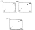
ところで、カラーブラウン管の画質を良好にするためには、画面全面のフォーカス特性を良好にすることが必要である。しかし上記一列配置の3電子ビームを放出する通常のインライン型電子銃を有するカラーブラウン管では、図7(a)に示すように、画面中央部のビームスポット1a をほぼ真円としても、周辺部のビームスポット1b は、偏向収差により水平方向に長い楕円状に歪み(横潰れ)、かつ垂直方向ににじみ2が発生する。
【0010】
これに対して、上記のように第5グリッドG5 を3分割し、その分割されたグリッドG51,G52,G53間に電子ビームの偏向にしたがって変化する四極子レンズを形成するダブルフォーカス方式の電子銃を有するカラーブラウン管では、図7(b)に示すように、上記偏向収差を補償して、画面周辺部のビームスポット1b のにじみを解消することができ、画面全面にわたり電子ビームをフォーカスさせることができる。しかしこのダブルフォーカス方式の電子銃でも、画面周辺部でのビームスポット1b の横潰れは解消できず、シャドウマスクの電子ビーム通過孔との干渉によりモアレを引起こし、画面上の文字などの表示が見にくくなるという問題がある。
【0011】
その対策として、第2グリッドの第3グリッドとの対向面に横長の溝を形成した電子銃がある。このように第2グリッドに横長の溝を形成すると、第2、第3グリッドにより形成されるプリフォーカスレンズの垂直方向の集束作用を水平方向の集束作用よりも強く、かつ主レンズに対する水平方向の仮想物点径を縮小、垂直方向の仮想物点径を拡大することができる。それにより、図7(c)に示すように、画面中央部のビームスポット1a の縦長とすると同時に、周辺部のビームスポット1b の横潰れを緩和して、シャドウマスクの電子ビーム通過孔との干渉により生ずるモアレを解消することができる。
【0012】
この電子銃では、第2グリッドの横長の溝を深くするほど、画面周辺部のビームスポット1b の横潰れを緩和することができるが、それにともなって、画面中央部のビームスポット1a を縦長が助長され、このビームスポットの垂直方向径の拡大により、画面中央部の解像度が劣化する。
【0013】
【発明が解決しようとする課題】
上記のように、カラーブラウン管の画質を良好にするためには、画面全面にわたり良好なフォーカス状態を保ち、かつビームスポットの楕円歪を少なくすることが必要である。
【0014】
この点、従来のQPF型ダブルフォーカス方式の電子銃は、四極子レンズを形成するグリッドに、電子ビームの偏向にしたがって増大する電圧を印加することにより、偏向収差によるビームスポットの垂直方向のにじみを解消することはできる。しかし画面周辺部でのビームスポットの横潰れを解消することはできず、シャドウマスクの電子ビーム通過孔との干渉によりモアレを引起こし、画面上の文字などの表示が見にくくなる。
【0015】
この画面周辺部でのビームスポットの横潰れを解消するために、第2グリッドの第3グリッドとの対向面に横長の溝を形成すると、画面周辺部のビームスポットの横潰れは解消できる。しかし画面中央部のビームスポットが縦長となり、画面中央部での解像度が劣化する。
【0016】
したがって上記従来の電子銃では、画面中央部での画像の見易さを重視すれば、画面周辺部の画像が劣化し、逆に画面周辺部での画像の見易さを重視すれば、画面中央部の画像が劣化する。そのため、従来のカラーブラウン管は、画面全面を良好なフォーカス状態にすることができず、妥協的な設計をおこなわなければならないという問題がある。
【0017】
この発明は、上記問題点を解決するためになされたものであり、画面全面にわたり、フォーカス特性を良好にし、かつビームスポットの楕円歪を小さくすることを目的とする。
【0020】
【課題を解決するための手段】
(1) カソード、このカソードに順次隣接かつ所定間隔離れて配置されカソードからの電子ビームを制御する第1、第2グリッド、これら第1、第2グリッドにより制御された電子ビームを加速、集束する第3グリッドおよび少なくとも3個のグリッドを有する電子銃と、この電子銃から放出される電子ビームを水平方向に偏向するピンクッション形水平偏向磁界および垂直方向に偏向するバレル形垂直偏向磁界を発生する偏向ヨークとを備えるカラーブラウン管装置において、電子銃を、第2グリッドと第3グリッドとの間に偏向ヨークの発生する磁界に同期して動的に変化する電圧が印加される補助第2グリッドを配置し、これら第2グリッド、補助第2グリッドおよび第3グリッドにより垂直方向の集束が水平方向の集束よりも強い非点収差をもちかつ補助第2グリッドに印加される動的に変化する電圧によりその非点収差の強度を動的に変化する電子レンズを形成し、電子ビーム進行方向に沿って第3グリッド以降に配置される上記3個のグリッドにより水平方向の集束が垂直方向の集束よりも強い非点収差をもちかつこれら3個のグリッドの両側に位置するグリッドに印加される動的に変化する電圧によりその非点収差の強度を動的に変化させる電子レンズを形成する構造とした。
【0021】
(2) (1)のカラーブラウン管において、補助第2グリッドに第2グリッドに印加される電圧を基準電圧として偏向ヨークの発生する磁界に同期して減少する電圧を印加し、3個のグリッドのうち、両側に位置するグリッドに中間に位置するグリッドに印加される電圧を基準電圧として偏向ヨークの発生する磁界に同期して増大する電圧を印加するようにした。
【0022】
(3) (1)または(2)のカラーブラウン管装置において、補助第2グリッドに水平方向の径が垂直方向の径よりも大きい非円形の電子ビーム通過孔を形成した。
【0023】
【発明の実施の形態】
以下、図面を参照してこの発明の実施の形態について説明する。
【0024】
図3にその一形態であるインライン型カラーブラウン管装置の構成を示す。このカラーブラウン管装置は、実質的に矩形状のパネル10と漏斗状のファンネル11からなる外囲器を有し、そのパネル10の内面に、青、緑、赤に発光するドット状の3色蛍光体層からなる蛍光体スクリーン12が設けられ、この蛍光体スクリーン12と対向して、その内側にシャドウマスク13が配置されている。一方、ファンネル11のネック15内に、同一水平面上を通るセンタービーム16G および一対のサイドビーム16B ,16R からなる一列配置の3電子ビーム16B ,16G ,16R を放出する下記電子銃17が配設されている。またファンネル11の径大部18とネック15との境界部付近の外側に、ピンクッション形水平偏向磁界およびバレル形垂直偏向磁界を発生する偏向ヨーク20が装着されている。そして、上記電子銃17から放出される3電子ビーム16B ,16G ,16R をファンネル11の外側に装着された偏向装置20の発生する水平、垂直磁界により偏向して、蛍光体スクリーン12を水平、垂直走査することにより、カラー画像を表示する構造に形成されている。
【0025】
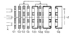
上記電子銃17は、QPF型ダブルフォーカス方式であり、図1に示すように、水平方向(H軸方向)に一列に配置された3個のカソードK、これらカソードKを各別に加熱する3個のヒータ(図示せず)および上記カソードKから順次蛍光体スクリーン方向に所定間隔離れて配置された第1乃至第6グリッドG1 〜G6 を有する。その第5グリッドG5 は、第4グリッドG4 から第6グリッドG6 方向に順次配置された3個のグリッドG51,G52,G53に分割されている。さらにこの電子銃17においては、第2グリッドG2 と第3グリッドG3 との間に補助第2グリッドG2sが配置されている。
【0026】
その第1、第2グリッドG1 ,G2 、補助第2グリッドG2s、第3、第4グリッドG3 ,G4 および第5グリッドG5 の分割されたグリッドG51,G52,G53のうち、中間に位置するグリッドG52は、それぞれカソードKの配列方向を長径とする一体構造の板状電極からなる。第5グリッドG5 の分割されたグリッドG51,G52,G53のうち、両側に位置するグリッドG51,G53は、それぞれカソードKの配列方向を長径とする一体構造の筒状電極からなる。また第6グリッドG6 は、カップ状電極からなる。
【0027】
その板状電極からなる第1、第2、第3、第4グリッドG1,G2,G3およびG4には、それぞれ3個のカソードKに対応して、3個の円形電子ビーム通過孔が水平方向に一列配置に形成されている。また筒状電極からなるグリッドG51,G53およびカップ状電極からなる第6グリッドG6の隣接グリッドとの対向面には、それぞれ3個のカソードKに対応して、同様に3個の円形電子ビーム通過孔が水平方向に一列配置に形成されている。これに対して、補助第2グリッドG2sには、図2に示すように、3個のカソードKに対応して、水平方向径が垂直方向径よりも大きい非円形電子ビーム通過孔22B,22G,22Rが水平方向に一列配置に形成されている。
【0028】
この電子銃17では、各カソードKに約150Vの電圧が印加され、第1グリッドG1 は接地され、第2グリッドG2 には、約800Vの電圧が印加される。補助第2グリッドG2sには、第2グリッドG2 に印加される電圧(約800V)を基準電圧として、偏向ヨークの発生する磁界に同期して動的に変化する電圧、すなわち、図4(a)および(b)に示すように、第2グリッドに印加される電圧24を基準電圧として、水平偏向電流25H および垂直偏向電流25V に同期して、放物線状に減少する電圧26H ,26V が印加される。第3グリッドG3 には、約6 kVの電圧が印加される。第4グリッドG4 は、管内で第2グリッドG2 に接続され、約800Vの電圧が印加される。第5グリッドG5 の分割されたグリッドG51,G52,G53のうち、中間に位置するグリッドG52は、管内で第3グリッドG3 に接続され、約6 kVの電圧が印加される。これに対して両側に位置するグリッドG51,G53は、管内で接続され、これらグリッドG51,G53には、グリッドG52に印加される電圧(約6 kV)を基準電圧として、偏向ヨークの発生する磁界に同期して動的に変化する電圧、すなわち、水平偏向電流および垂直偏向電流に同期して、放物線状に増大する電圧が印加される。また第6グリッドG6 には、約26 kVの高電圧が印加される。
【0029】
上記電圧の印加により、この電子銃17では、カソードKおよび第1、第2グリッドG1 ,G2 により電子ビームを発生し、かつ後述する主レンズに対する物点を形成する三極部が形成され、第2グリッドG2 、補助第2グリッドG2sおよび第3グリッドG3 により、上記三極部からの電子ビームを予備集束するプリフォーカスレンズが、さらに第3、第4グリッドG3 ,G4 および第4グリッドG4 側に位置する第5グリッドG5 の分割されたグリッドG51により、上記プリフォーカスレンズにより予備集束された電子ビームをさらに予備集束するサブレンズが形成される。また第5グリッドG5 の分割された3個のグリッドG51,G52,G53により、偏向収差を補償する四極子レンズが形成される。さらに第6グリッドG6 側に位置する第5グリッドG5 の分割されたグリッドG53と第6グリッドG6 とにより、電子ビームを最終的に蛍光体スクリーン上に集束する主レンズが形成される。
【0030】
この電子銃17では、電子ビームが偏向されることなく蛍光体スクリーンの中央に向かうとき(無偏向時)は、三極部からの電子ビームは、第2グリッドG2 、補助第2グリッドG2sおよび第3グリッドG3 により形成されるプリフォーカスレンズにより予備集束されるが、この場合、補助第2グリッドG2sには水平方向径が垂直方向径よりも大きい非円形電子ビーム通過孔が形成されているため、弱い負の非点収差(垂直方向の集束が水平方向の集束よりも強い非点収差)を受け、主レンズに対する水平方向の仮想物点径が縮小し、水平方向の発散角が拡大する。ついでこのプリフォーカスレンズにより予備集束された電子ビームは、第3、第4グリッドG3 ,G4 および第5グリッドG5 の分割されたグリッドG51により形成されるサブレンズにより、さらに予備集束される。つぎの第5グリッドG5 の分割された3個のグリッドG51,G52,G53間には、この場合、電子レンズは形成されないので、上記サブレンズにより予備集束された電子ビームは、これらグリッドG51,G52,G53を通過し、その後、第5グリッドG5 の分割されたグリッドG53と第6グリッドG6 とにより形成される主レンズにより最終的に集束され、蛍光体スクリーンの中央に入射する。
【0031】
その結果、図5に示すように、蛍光体スクリーンの中央に入射する電子ビームのビームスポット28a は、上記補助第2グリッドG2sによる弱い負の非点収差によりやや縦長のほぼ円形となる。
【0032】
これに対して、電子ビームが蛍光体スクリーンの周辺方向に偏向されるとき(偏向時)は、三極部からの電子ビームは、第2グリッドG2 、補助第2グリッドG2sおよび第3グリッドG3 により形成されるプリフォーカスレンズにより予備集束されるが、この場合は、無偏向時のときよりも補助第2グリッドG2sの電圧が偏向角の増大にともなって低くなる(図4参照)ため、強い負の非点収差を受け、無偏向時のときよりも主レンズに対する水平方向の仮想物点径がより小さく、垂直方向の仮想物点径がより拡大する。また無偏向時のときよりも水平方向の発散角が拡大し、垂直方向の発散角が縮小する。ついで上記プリフォーカスレンズにより予備集束された電子ビームは、第3、第4グリッドG3 ,G4 および第5グリッドG5 の分割されたグリッドG51により形成されるサブレンズにより、さらに予備集束される。ついでこの偏向時には、第5グリッドG5 の分割されたグリッドG51,G53に、グリッドG52に印加される電圧を基準電圧として偏向角の増大にともなって高くなる電圧が印加されるため、これらグリッドG51,G52,G53により、正の非点収差(水平方向の集束が垂直方向の集束よりも強い非点収差)を受け、上記プリフォーカスレンズによる発散角が補正され、かつ偏向収差を補正する作用を受ける。その後、第5グリッドG5 の分割されたグリッドG53と第6グリッドG6 とにより形成される主レンズにより最終的に集束され、蛍光体スクリーンの周辺部に入射する。
【0033】
この蛍光体スクリーンの周辺部に入射する電子ビームのビームスポットは、上記補助第2グリッドG2sによる強い負の非点収差により水平方向の仮想物点径が縮小するため、水平方向径が縮小する。一方、垂直方向の仮想物点径の拡大により垂直方向径が拡大する。その結果、図5に示したように、蛍光体スクリーンの周辺部に入射する電子ビームのビームスポット28b は、横つぶれが緩和され、ほぼ円形となる。
【0034】
したがって上記のように電子銃17を構成すると、画面全面にわたりビームスポットの楕円歪を緩和してほぼ円形とすることができ、かつ画面全面のフォーカス状態を均一にして、良好な画像を表示するカラーブラウン管装置を構成することができる。
【0035】
【発明の効果】
上述のように、カソード、このカソードに順次隣接かつ所定間隔離れて配置されカソードからの電子ビームを制御する第1、第2グリッド、これら第1、第2グリッドにより制御された電子ビームを加速、集束する第3グリッドおよび少なくとも1個のグリッドを有する電子銃と、この電子銃から放出される電子ビームを水平方向に偏向するピンクッション形水平偏向磁界および垂直方向に偏向するバレル形垂直偏向磁界を発生する偏向ヨークとを備えるカラーブラウン管装置において、第2グリッドと第3グリッドとの間に偏向ヨークの発生する磁界に同期して動的に変化する電圧が印加される補助第2グリッドを配置し、これら第2グリッド、補助第2グリッドおよび第3グリッドにより垂直方向の集束が水平方向の集束よりも強い非点収差をもちかつ補助第2グリッドに印加される動的に変化する電圧によりその非点収差の強度を動的に変化させる電子レンズを形成する構造とすると、電子ビームの仮想物点径を動的に変化させ、画面周辺部のビームスポットの横つぶれを緩和でき、画面全面のフォーカス状態を均一にして、良好な画像を表示するカラーブラウン管装置を構成することができる。
【図面の簡単な説明】
【図1】この発明の実施の一形態に係るインライン型カラーブラウン管の電子銃の構成を示す図である。
【図2】上記電子銃の補助第2グリッドの構成を示す図である。
【図3】この発明の実施の一形態であるインライン型カラーブラウン管の構成を示す図である。
【図4】図4(a)および(b)はそれぞれ上記補助第2グリッドに印加される偏向電流に同期して変化する電圧を示す図である。
【図5】この発明の実施の一形態であるインライン型カラーブラウン管の蛍光体スクリーン上のビームスポットの形状を説明するための図である。
【図6】従来のインライン型カラーブラウン管の電子銃の構成を示す図である。
【図7】図7(a)は従来の通常のインライン型電子銃を有するカラーブラウン管の蛍光体スクリーン上のビームスポットの形状を説明するための図、図7(b)は従来のQPF型ダブルフォーカス方式電子銃を有するカラーブラウン管の蛍光体スクリーン上のビームスポットの形状を説明するための図、図7(c)はそのQPF型ダブルフォーカス方式電子銃の第2グリッドに横長の溝を形成した電子銃を有するカラーブラウン管の蛍光体スクリーン上のビームスポットの形状を説明するための図である。
【符号の説明】
12…蛍光体スクリーン
16B ,16R …一対のサイドビーム
16G …センタービーム
17…電子銃
20…偏向ヨーク
G1 …第1グリッド
G2 …第2グリッド
G2s…補助第2グリッド
G3 …第3グリッド
G4 …第4グリッド
G5 …第5グリッド
G51…第5グリッドの分割されたグリッド
G52…第5グリッドの分割されたグリッド
G53…第5グリッドの分割されたグリッド
G6 …第6グリッド
K …カソード[0001]
BACKGROUND OF THE INVENTION
The present invention relates to a color cathode ray tube device, and more particularly, to a color cathode ray tube device that displays an excellent image by reducing elliptic distortion of a beam spot at the periphery of a screen.
[0002]
[Prior art]
In general, a color cathode ray tube has an envelope consisting of a panel and a funnel, and deflects three electron beams emitted from an electron gun disposed in the neck of the funnel by horizontal and vertical deflection magnetic fields generated by a deflecting device. The phosphor screen provided on the inner surface of the panel is horizontally and vertically scanned through a shadow mask to display a color image.
[0003]
In such a color cathode ray tube, in particular, the electron gun is an in-line type electron gun that emits three electron beams arranged in a row consisting of a center beam and a pair of side beams that pass on the same horizontal plane, and the horizontal deflection magnetic field generated by the deflection device is pinned. A self-convergence in-line type color cathode ray tube that self-concentrates the three electron beams arranged in a row is widely used as a cushion type and a non-uniform magnetic field having a vertical deflection magnetic field as a barrel type.
[0004]
There are various types of electron guns that emit three electron beams arranged in a row, and one of them is an electron gun called a QPF (Quadra Potential Focus) type double focus method. As shown in FIG. 6, the QPF type double focus type electron gun has three cathodes K arranged in a row in the horizontal direction (H-axis direction), and the cathodes K are sequentially arranged in the phosphor screen direction. The first to sixth grids G1 to G6 are provided, and the fifth grid G5 is divided into three grids G51, G52, and G53. These grids G1 to G4, G51 to G53, and G6 are each formed in an integral structure, and three electron beam passage holes are formed in a row in the horizontal direction corresponding to the three cathodes K, respectively.
[0005]
In this electron gun, a voltage of about 150 V is applied to each cathode K, the first grid G1 is grounded, a voltage of about 800 V is applied to the second grid G2, and a voltage of about 6 kV is applied to the third grid G3. The fourth grid G4 is connected to the second grid G2 in the tube and a voltage of about 800V is applied. Of the three grids G51, G52, and G53 of the fifth grid G5, the intermediate grid G52 is connected to the third grid G3, and a voltage of about 6 kV is applied, and the grids G51 and G53 on both sides are connected to each other. Using the voltage applied to the intermediate grid G52 as a reference voltage, a dynamically changing voltage that increases as the electron beam deflects is applied. A high voltage of about 26 kV is applied to the sixth grid G6.
[0006]
By applying such a voltage, in this electron gun, the cathode K and the first and second grids G1, G2 generate an electron beam and form a triode that forms an object point with respect to the main lens described later. A prefocus lens for prefocusing the electron beam from the triode portion by the second and third grids G2 and G3 is further located on the third, fourth grid G3 and fourth grid G4 side. A sub-lens for further prefocusing the electron beam preliminarily focused by the prefocus lens is formed by the grid G51 obtained by dividing the grid G5. A quadrupole lens is formed by the three grids G51, G52, and G53 obtained by dividing the fifth grid G5. Further, a main lens for finally focusing the electron beam on the phosphor screen is formed by the divided grid G53 and the sixth grid G6 of the fifth grid G5 located on the sixth grid G6 side.
[0007]
In this electron gun, when the electron beam is directed toward the center of the phosphor screen without being deflected, a quadrupole lens is not formed between the three divided grids G51, G52, and G53 of the fifth grid G5. The electron beam from the unit is focused on the center of the phosphor screen by the prefocus lens, the sub lens, and the main lens.
[0008]
On the other hand, when the electron beam is deflected toward the periphery of the phosphor screen, the voltages of the grids G51 and G53 on both sides of the fifth grid G5 are increased according to the deflection angle of the electron beam, and divided into three. A quadrupole lens is formed between the grids G51, G52, and G53. At the same time, as the voltage of the grid G53 increases, the strength of the main lens formed by the grid G53 and the sixth grid G6 decreases. As a result, the distance from the electron gun to the phosphor screen is increased electro-optically, the lens magnification changes corresponding to the farther image point, and the horizontal deflection magnetic field generated by the deflection yoke is pincushion type, vertical It compensates for deflection aberration caused by the deflection magnetic field being barrel-shaped.
[0009]
Incidentally, in order to improve the image quality of the color cathode ray tube, it is necessary to improve the focus characteristics of the entire screen. However, in a color cathode ray tube having a normal in-line type electron gun that emits three electron beams arranged in a row, as shown in FIG. 7A, the beam spot 1a at the center of the screen is almost a perfect circle. The
[0010]
On the other hand, as described above, the fifth grid G5 is divided into three, and a double focus type electron gun that forms a quadrupole lens that changes in accordance with the deflection of the electron beam between the divided grids G51, G52, and G53. As shown in FIG. 7B, the color cathode ray tube having the above can compensate for the deflection aberration and can eliminate the blur of the
[0011]
As a countermeasure, there is an electron gun in which a horizontally long groove is formed on the surface of the second grid facing the third grid. When a horizontally long groove is formed in the second grid in this way, the vertical focusing action of the prefocus lens formed by the second and third grids is stronger than the horizontal focusing action, and in the horizontal direction with respect to the main lens. The virtual object point diameter can be reduced and the virtual object point diameter in the vertical direction can be increased. As a result, as shown in FIG. 7 (c), the beam spot 1a at the center of the screen is made to be vertically long, and at the same time, the lateral collapse of the
[0012]
In this electron gun, as the horizontal groove of the second grid is deepened, the lateral collapse of the
[0013]
[Problems to be solved by the invention]
As described above, in order to improve the image quality of the color cathode ray tube, it is necessary to maintain a good focus state over the entire screen and reduce the elliptic distortion of the beam spot.
[0014]
In this regard, the conventional QPF type double focus type electron gun applies a voltage that increases in accordance with the deflection of the electron beam to the grid forming the quadrupole lens, thereby blurring the beam spot in the vertical direction due to deflection aberration. It can be solved. However, the horizontal collapse of the beam spot at the periphery of the screen cannot be eliminated, and moire is caused by interference with the electron beam passage hole of the shadow mask, making it difficult to see the display of characters on the screen.
[0015]
In order to eliminate the horizontal collapse of the beam spot at the peripheral portion of the screen, if the horizontally elongated groove is formed on the surface of the second grid facing the third grid, the horizontal collapse of the beam spot at the peripheral portion of the screen can be eliminated. However, the beam spot at the center of the screen becomes vertically long, and the resolution at the center of the screen deteriorates.
[0016]
Therefore, in the above conventional electron gun, if emphasis is placed on the visibility of the image in the center portion of the screen, the image in the peripheral portion of the screen will be deteriorated. The image at the center is deteriorated. For this reason, the conventional color cathode ray tube has a problem that the entire screen cannot be brought into a favorable focus state and must be designed in a compromise manner.
[0017]
The present invention has been made to solve the above-described problems, and has an object to improve the focus characteristics over the entire screen and reduce the elliptic distortion of the beam spot.
[0020]
[Means for Solving the Problems]
( 1 ) A cathode, first and second grids that are sequentially adjacent to the cathode and spaced apart by a predetermined distance to control the electron beam from the cathode, and the electron beam controlled by the first and second grids is accelerated and focused. An electron gun having a third grid and at least three grids, and a pincushion type horizontal deflection magnetic field for deflecting an electron beam emitted from the electron gun in the horizontal direction and a barrel type vertical deflection magnetic field for deflecting in the vertical direction are generated. In a color cathode ray tube apparatus including a deflection yoke, an auxiliary second grid to which a dynamically changing voltage is applied between the second grid and the third grid in synchronization with a magnetic field generated by the deflection yoke is applied to the electron gun. Placed, and these 2nd grid, auxiliary 2nd grid and 3rd grid have stronger vertical focusing than horizontal focusing An electron lens having astigmatism and dynamically changing the intensity of astigmatism is formed by a dynamically changing voltage applied to the auxiliary second grid, and the third and subsequent grids are formed along the electron beam traveling direction. With the three grids arranged, the horizontal focusing has a stronger astigmatism than the vertical focusing and is caused by the dynamically changing voltage applied to the grids located on both sides of the three grids. An electron lens that dynamically changes the intensity of astigmatism is formed.
[0021]
( 2 ) In the color cathode-ray tube of ( 1 ), a voltage that decreases in synchronization with the magnetic field generated by the deflection yoke is applied to the auxiliary second grid using the voltage applied to the second grid as a reference voltage. Among them, a voltage that increases in synchronization with the magnetic field generated by the deflection yoke is applied to the grids positioned on both sides using the voltage applied to the grid positioned in the middle as a reference voltage.
[0022]
( 3 ) In the color cathode ray tube apparatus of (1) or (2), a non-circular electron beam passage hole having a horizontal diameter larger than a vertical diameter is formed in the auxiliary second grid.
[0023]
DETAILED DESCRIPTION OF THE INVENTION
Embodiments of the present invention will be described below with reference to the drawings.
[0024]
FIG. 3 shows a configuration of an inline type color cathode ray tube device as one form thereof. This color cathode-ray tube apparatus has an envelope made up of a substantially
[0025]
The
[0026]
Among the divided grids G51, G52, and G53 of the first and second grids G1 and G2, the auxiliary second grid G2s, the third, fourth grids G3 and G4, and the fifth grid G5, the grid G52 located in the middle. Are each composed of an integrally structured plate-like electrode having a major axis in the arrangement direction of the cathodes K. Of the divided grids G51, G52, and G53 of the fifth grid G5, the grids G51 and G53 located on both sides are each formed of an integrally structured cylindrical electrode having a major axis in the arrangement direction of the cathode K. The sixth grid G6 is composed of cup-shaped electrodes.
[0027]
The first, second, third, and fourth grids G1, G2, G3, and G4 made of the plate-like electrodes have three circular electron beam passage holes in the horizontal direction corresponding to the three cathodes K, respectively. Are arranged in a row . Similarly, three circular electron beam passes corresponding to the three cathodes K on the opposing surfaces of the grids G51 and G53 made of cylindrical electrodes and the adjacent grid of the sixth grid G6 made of cup-shaped electrodes. The holes are formed in a row in the horizontal direction. On the other hand, in the auxiliary second grid G2s, as shown in FIG. 2, corresponding to the three cathodes K, the noncircular electron beam passage holes 22B, 22G, 22R is formed in a row in the horizontal direction.
[0028]
In this
[0029]
By applying the voltage, the
[0030]
In this
[0031]
As a result, as shown in FIG. 5, the
[0032]
On the other hand, when the electron beam is deflected in the peripheral direction of the phosphor screen (during the deflection), the electron beam from the triode is caused by the second grid G2, the auxiliary second grid G2s, and the third grid G3. Pre-focusing is performed by the formed prefocus lens. In this case, however, the voltage of the auxiliary second grid G2s becomes lower as the deflection angle increases (see FIG. 4) than in the case of no deflection (see FIG. 4). As a result of this astigmatism, the virtual object point diameter in the horizontal direction relative to the main lens is smaller and the virtual object point diameter in the vertical direction is larger than in the case of no deflection. Also, the divergence angle in the horizontal direction is increased and the divergence angle in the vertical direction is reduced as compared with the case of no deflection. Next, the electron beam prefocused by the prefocus lens is further prefocused by a sub lens formed by a grid G51 divided from the third, fourth grid G3, G4 and the fifth grid G5. Next, at the time of this deflection, since the voltage applied to the grid G52 as a reference voltage is applied to the divided grids G51 and G53 of the fifth grid G5, the voltage that increases as the deflection angle increases is applied. G52 and G53 receive positive astigmatism (horizontal focusing is stronger than vertical focusing), the divergence angle by the prefocus lens is corrected, and the deflection aberration is corrected. . Thereafter, the light is finally focused by the main lens formed by the divided grid G53 and the sixth grid G6 of the fifth grid G5, and enters the peripheral portion of the phosphor screen.
[0033]
The beam spot of the electron beam incident on the peripheral portion of the phosphor screen is reduced in the horizontal diameter because the virtual object spot diameter in the horizontal direction is reduced due to strong negative astigmatism caused by the auxiliary second grid G2s. On the other hand, the vertical diameter is increased by increasing the virtual object point diameter in the vertical direction. As a result, as shown in FIG. 5, the beam spot 28b of the electron beam incident on the peripheral portion of the phosphor screen is relaxed and becomes almost circular.
[0034]
Therefore, when the
[0035]
【The invention's effect】
As described above, the cathode, the first and second grids, which are sequentially adjacent to the cathode and spaced apart by a predetermined distance and control the electron beam from the cathode, accelerate the electron beam controlled by the first and second grids, An electron gun having a third grid for focusing and at least one grid, a pincushion type horizontal deflection magnetic field for deflecting an electron beam emitted from the electron gun in the horizontal direction, and a barrel type vertical deflection magnetic field for deflecting in the vertical direction In a color cathode ray tube apparatus including a deflection yoke that generates the auxiliary second grid to which a voltage that dynamically changes in synchronization with the magnetic field generated by the deflection yoke is disposed between the second grid and the third grid. The astigmatism that the vertical focusing is stronger than the horizontal focusing due to the second grid, the auxiliary second grid, and the third grid. A structure that forms an electron lens that has a difference and dynamically changes the intensity of astigmatism by a dynamically changing voltage applied to the auxiliary second grid, and dynamically changes the virtual object point diameter of the electron beam. Therefore, it is possible to reduce the horizontal collapse of the beam spot at the periphery of the screen, make the focus state of the entire screen uniform, and configure a color CRT device that displays a good image.
[Brief description of the drawings]
FIG. 1 is a diagram showing a configuration of an electron gun of an inline type color cathode ray tube according to an embodiment of the present invention.
FIG. 2 is a diagram showing a configuration of an auxiliary second grid of the electron gun.
FIG. 3 is a diagram showing a configuration of an inline type color cathode ray tube according to an embodiment of the present invention.
FIGS. 4A and 4B are diagrams showing voltages that change in synchronization with a deflection current applied to the auxiliary second grid, respectively.
FIG. 5 is a view for explaining the shape of a beam spot on a phosphor screen of an inline type color cathode ray tube according to an embodiment of the present invention.
FIG. 6 is a diagram showing a configuration of a conventional electron gun of an inline type color cathode ray tube.
7A is a diagram for explaining the shape of a beam spot on a phosphor screen of a color cathode ray tube having a conventional normal in-line electron gun, and FIG. 7B is a conventional QPF double FIG. 7C is a diagram for explaining the shape of a beam spot on a phosphor screen of a color cathode ray tube having a focus type electron gun. FIG. 7C shows a horizontally long groove formed in the second grid of the QPF type double focus type electron gun. It is a figure for demonstrating the shape of the beam spot on the fluorescent substance screen of the color cathode ray tube which has an electron gun.
[Explanation of symbols]
12 ... Phosphor screens 16B, 16R ... Pair of
Claims (3)
上記電子銃は上記第2グリッドと第3グリッドとの間に上記偏向ヨークの発生する磁界に同期して動的に変化する電圧が印加される補助第2グリッドが配置され、これら第2グリッド、補助第2グリッドおよび第3グリッドにより垂直方向の集束が水平方向の集束よりも強い非点収差をもちかつ上記補助第2グリッドに印加される動的に変化する電圧により上記非点収差の強度が動的に変化する電子レンズを形成し、電子ビーム進行方向に沿って第3グリッド以降に配置される上記3個のグリッドにより形成される四極子レンズは水平方向の集束が垂直方向の集束よりも強い非点収差をもちかつこれら3個のグリッドの両側に位置するグリッドに印加される動的に変化する電圧により上記非点収差の強度が動的に変化する電子レンズを形成することを特徴とするカラーブラウン管装置。A cathode, first and second grids that are sequentially adjacent to the cathode and spaced apart from each other by a predetermined distance to control the electron beam from the cathode, and the electron beam controlled by the first and second grids is accelerated and focused. 3 an electron gun having a grid and at least three grids, deflection for generating differentially barrel type vertical deflection magnetic field for deflecting the pincushion horizontal deflection magnetic field and the vertical deflecting the electron beams in the horizontal direction emitted from the electron gun In a color cathode ray tube device comprising a yoke,
In the electron gun, an auxiliary second grid to which a voltage that dynamically changes in synchronization with a magnetic field generated by the deflection yoke is applied is disposed between the second grid and the third grid. The auxiliary second grid and the third grid have astigmatism in which the vertical focusing is stronger than the horizontal focusing, and the intensity of the astigmatism is increased by the dynamically changing voltage applied to the auxiliary second grid. form forms a dynamically changing electron lens, quadrupole lens formed by the three grids being disposed in the third and subsequent grid along the electron beam traveling direction from the focussing focusing in the horizontal direction in the vertical direction to form an electron lens intensity of the astigmatic aberration is dynamically changed by dynamically changing voltage is also applied to a strong astigmatism have and located on either side of these three grid grid Color cathode ray tube apparatus characterized by.
Priority Applications (8)
| Application Number | Priority Date | Filing Date | Title |
|---|---|---|---|
| JP01629797A JP3734327B2 (en) | 1997-01-30 | 1997-01-30 | Color cathode ray tube equipment |
| TW091219557U TW534451U (en) | 1997-01-30 | 1998-01-26 | Color ray tube |
| CNB981062520A CN1153249C (en) | 1997-01-30 | 1998-01-27 | Colour Bulao'en tube |
| MYPI98000376A MY118543A (en) | 1997-01-30 | 1998-01-27 | A color cathode ray tube |
| EP98101405A EP0856869B1 (en) | 1997-01-30 | 1998-01-27 | A color cathode ray tube |
| DE69803317T DE69803317T2 (en) | 1997-01-30 | 1998-01-27 | Color cathode ray tube |
| KR1019980003629A KR100261719B1 (en) | 1997-01-30 | 1998-01-30 | Color cathode ray tube |
| US09/016,408 US5994826A (en) | 1997-01-30 | 1998-01-30 | Color cathode ray tube |
Applications Claiming Priority (1)
| Application Number | Priority Date | Filing Date | Title |
|---|---|---|---|
| JP01629797A JP3734327B2 (en) | 1997-01-30 | 1997-01-30 | Color cathode ray tube equipment |
Publications (2)
| Publication Number | Publication Date |
|---|---|
| JPH10214574A JPH10214574A (en) | 1998-08-11 |
| JP3734327B2 true JP3734327B2 (en) | 2006-01-11 |
Family
ID=33463175
Family Applications (1)
| Application Number | Title | Priority Date | Filing Date |
|---|---|---|---|
| JP01629797A Expired - Fee Related JP3734327B2 (en) | 1997-01-30 | 1997-01-30 | Color cathode ray tube equipment |
Country Status (1)
| Country | Link |
|---|---|
| JP (1) | JP3734327B2 (en) |
Families Citing this family (2)
| Publication number | Priority date | Publication date | Assignee | Title |
|---|---|---|---|---|
| JP2000048737A (en) | 1998-07-27 | 2000-02-18 | Toshiba Electronic Engineering Corp | Color picture tube device |
| KR100370070B1 (en) * | 2000-07-14 | 2003-01-30 | 엘지전자 주식회사 | Color cathode ray tube |
-
1997
- 1997-01-30 JP JP01629797A patent/JP3734327B2/en not_active Expired - Fee Related
Also Published As
| Publication number | Publication date |
|---|---|
| JPH10214574A (en) | 1998-08-11 |
Similar Documents
| Publication | Publication Date | Title |
|---|---|---|
| US6339284B1 (en) | Color cathode ray tube apparatus having auxiliary grid electrodes | |
| US6614156B2 (en) | Cathode-ray tube apparatus | |
| KR20000011965A (en) | A color cathode ray tube | |
| JP3734327B2 (en) | Color cathode ray tube equipment | |
| KR100219900B1 (en) | An electron-gun for color crt | |
| JP3672390B2 (en) | Electron gun for color cathode ray tube | |
| JPH08148095A (en) | Electron gun and color cathode-ray tube provided with this electron gun | |
| JPH05325825A (en) | Electron gun for color cathode-ray tube | |
| EP1050896A1 (en) | Cathode-ray tube | |
| JP3655708B2 (en) | Color cathode ray tube | |
| US6479951B2 (en) | Color cathode ray tube apparatus | |
| JP3315173B2 (en) | Color picture tube equipment | |
| JP2000082417A (en) | Cathode-ray tube | |
| KR100646910B1 (en) | Cathode ray tube apparatus | |
| KR100383857B1 (en) | Color cathode-ray tube device | |
| JP2878731B2 (en) | Color picture tube equipment | |
| JP2000357469A (en) | Color cathode-ray tube device | |
| JP2000123756A (en) | Color cathode ray tube | |
| JPH02135650A (en) | Color cathode-ray tube | |
| JPH07147145A (en) | Electron gun for cathode-ray tube | |
| JPH11167880A (en) | Color cathode-ray tube | |
| JPH09134680A (en) | Color picture tube device | |
| JPH08129967A (en) | Color picture tube device | |
| JPH10289671A (en) | Color picture tube | |
| JPH11144643A (en) | Color cathode-ray tube device |
Legal Events
| Date | Code | Title | Description |
|---|---|---|---|
| A521 | Written amendment |
Free format text: JAPANESE INTERMEDIATE CODE: A523 Effective date: 20040113 |
|
| A621 | Written request for application examination |
Free format text: JAPANESE INTERMEDIATE CODE: A621 Effective date: 20040113 |
|
| A977 | Report on retrieval |
Free format text: JAPANESE INTERMEDIATE CODE: A971007 Effective date: 20050127 |
|
| A131 | Notification of reasons for refusal |
Free format text: JAPANESE INTERMEDIATE CODE: A131 Effective date: 20050301 |
|
| A521 | Written amendment |
Free format text: JAPANESE INTERMEDIATE CODE: A523 Effective date: 20050426 |
|
| RD04 | Notification of resignation of power of attorney |
Free format text: JAPANESE INTERMEDIATE CODE: A7424 Effective date: 20050509 |
|
| A131 | Notification of reasons for refusal |
Free format text: JAPANESE INTERMEDIATE CODE: A131 Effective date: 20050628 |
|
| A521 | Written amendment |
Free format text: JAPANESE INTERMEDIATE CODE: A523 Effective date: 20050829 |
|
| TRDD | Decision of grant or rejection written | ||
| A01 | Written decision to grant a patent or to grant a registration (utility model) |
Free format text: JAPANESE INTERMEDIATE CODE: A01 Effective date: 20050927 |
|
| A61 | First payment of annual fees (during grant procedure) |
Free format text: JAPANESE INTERMEDIATE CODE: A61 Effective date: 20051018 |
|
| R150 | Certificate of patent or registration of utility model |
Free format text: JAPANESE INTERMEDIATE CODE: R150 |
|
| LAPS | Cancellation because of no payment of annual fees |