JP3733985B2 - Drop-in stove sealing device - Google Patents
Drop-in stove sealing device Download PDFInfo
- Publication number
- JP3733985B2 JP3733985B2 JP04001997A JP4001997A JP3733985B2 JP 3733985 B2 JP3733985 B2 JP 3733985B2 JP 04001997 A JP04001997 A JP 04001997A JP 4001997 A JP4001997 A JP 4001997A JP 3733985 B2 JP3733985 B2 JP 3733985B2
- Authority
- JP
- Japan
- Prior art keywords
- packing
- stove
- flange
- drop
- top plate
- Prior art date
- Legal status (The legal status is an assumption and is not a legal conclusion. Google has not performed a legal analysis and makes no representation as to the accuracy of the status listed.)
- Expired - Fee Related
Links
- 238000007789 sealing Methods 0.000 title claims description 14
- 238000012856 packing Methods 0.000 claims description 50
- 230000002093 peripheral effect Effects 0.000 claims description 24
- 238000003780 insertion Methods 0.000 claims description 6
- 230000037431 insertion Effects 0.000 claims description 6
- 238000005452 bending Methods 0.000 claims description 3
- 230000000694 effects Effects 0.000 description 2
- 238000009434 installation Methods 0.000 description 2
- 238000012423 maintenance Methods 0.000 description 2
- 235000014347 soups Nutrition 0.000 description 2
- 238000004140 cleaning Methods 0.000 description 1
- 230000005574 cross-species transmission Effects 0.000 description 1
- 230000001771 impaired effect Effects 0.000 description 1
- 239000000463 material Substances 0.000 description 1
- 230000001105 regulatory effect Effects 0.000 description 1
Images


Landscapes
- Combinations Of Kitchen Furniture (AREA)
Description
【0001】
【発明の属する技術分野】
本発明は、ドロップインこんろにおけるシール装置に関する。
【0002】
【従来の技術】
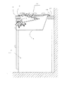
従来のドロップインこんろ30は、図6及び図7に示すように、こんろ本体6をカウンタトップ2に設けた開口の口縁部5に吊持させ、更に、こんろ本体6の上面を覆うトッププレート9をカウンタトップ2上に載置している。また、こんろ本体6とカウンタトップ2との間及びトッププレート9とカウンタトップ2との間には環状の耐熱性ゴム等からなる共通1個のパッキン17を介在させてカウンタトップ2上にこぼれ落ちた煮汁等がこんろ本体6に進入することがないようにその間をシールしている。パッキン17は内周側にこんろ本体6の外周縁部のフランジ6aを横から挿着する挿着部17a、外周側にトッププレート脚9a載置用の載置部17bを備えたものが知られている(実開平6ー4507)。
【0003】
【発明が解決しようとする課題】
しかしながらこのドロップインこんろ30は、こんろ本体6のフランジ6aにパッキン17の挿着部17aを横から挿着してカウンタトップ2への据付けを行なっているため、据付け後のパッキン17はフランジ6aとカウンタトップ2に挟まれた状態、つまりこんろ本体6の重量がフランジ6aを介してパッキン17にかかった状態で据え付けられているため、一旦カウンタトップ2に据付けるとパッキン17のみを外すことが困難となり、パッキン17の清掃や破損時の交換において、わざわざこんろ本体6の固定部材やガス配管を外した後にこんろ本体6を持ち上げてパッキン17を取り外して掃除や交換を行なう必要があった。また、こんろ本体6の全重量がパッキン17に直接かかるため、いわゆる締め殺しの状態になりパッキン17の弾性が急速に失われる恐れがある。また、こんろ本体6が取付け初期の位置より下がってしまい固定部材や配管に余分な力が加わり、それらの取り外しが難しくなるといった問題も生じる。
【0004】
本発明のドロップインこんろのシール装置は上記課題を解決し、パッキンの脱着を容易にし、安定したシール性を永い間保持し、且つメンテナンス性を向上させることを目的とする。
【0005】
【課題を解決するための手段】
上記課題を解決する本発明の請求項1記載のドロップインこんろのシール装置は、こんろ本体をその外周縁部のフランジをカウンタトップに設けた開口の口縁部に載置して吊持させると共に、こんろ本体の上面を覆うトッププレートを該カウンタトップ上に環状のパッキンを介して載置させたドロップインこんろのシール装置において、
上記フランジの外周端を上方に立上げ、更にその先端を水平方向の外側に折曲げた断面L字状の環状フランジアップを形成すると共に、上記パッキンの内周側底面に該フランジアップに上から挿着する断面L字状の挿着部を備え、且つ該パッキンの外周側上面に該トッププレートを載置する載置部を設けたことを要旨とする。
【0006】
上記構成を有する本発明のドロップインこんろのシール装置は、こんろ本体の断面L字状のフランジアップにパッキンの断面L字状の挿着部を上から挿着し、こんろ本体をカウンタトップに設けた開口の口縁部に吊持させる。パッキンは、フランジアップの水平曲げ部分によりカウンタトップに押し付けられる。従って、カウンタトップとこんろ本体との間がパッキンによりシールされる。また、パッキンはこんろ本体の全重量がかかるわけでなく、パッキンのしめしろはカウンタトップに吊持されるフランジ面とで規制されるため、パッキンが必要以上に圧縮されず、常に適正な弾性を保有すると共に、こんろ本体をカウンタトップに据え付けた状態のままでパッキンの着脱を自由に行なうことができる。また、パッキンの外周に設けた載置部にトッププレートを載置し、トッププレートの重みにより更に載置部をカウンタトップに押しつけるので、トッププレートとカウンタトップとの間を確実にシールすることができる。
【0007】
【発明の実施の形態】
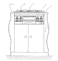
以上説明した本発明の構成・作用を一層明らかにするために、以下本発明のドロップインこんろのシール装置の好適な実施例について説明する。図1,図2は、本発明の一実施例としてのドロップインこんろの取付け外観図である。
キッチンユニット1の上方にカウンタトップ2を備え、カウンタトップ2の下部空間の上側にドロップインこんろ3、下側に収納庫4を配している。
【0008】
ドロップインこんろ3は、こんろ本体6と、こんろ本体6に収められたバーナ8及び点滅器12等と、こんろ本体6の上面を覆うトッププレート9とから構成されている。
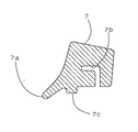
こんろ本体6は、図2,図4に示すように、フランジ6aによりカウンタトップ2に設けた開口の口縁部5に吊持されている。フランジ6aの外周縁部には、先端を上方に立上げ、更に外側に曲げ部6cを備えた断面L字状のフランジアップ6bが形成されている。トッププレート9は、環状のパッキン7を介してカウンタトップ2上に載置されている。パッキン7は、図5に示すように、内周側底面にこんろ本体6のフランジアップ6bに上から挿着する断面略L字状の環状の溝7b,外周側上面にトッププレート9の外周縁部9aを載置する舌状の載置部7a,中間部底面にパッキン7を支える凸部7cが設けられ、凸部7cから溝7bの水平部分までの高さはこんろ本体6のフランジアップ6bの高さより大きく設定されている。
【0009】
つまり、パッキン7は、内周側の上下方向に厚い肉厚部分と、外周側の舌状の肉薄部分とを備え、肉厚部分の底面周方向に断面L字状の溝7bを施して、その溝7bにこんろ本体6のフランジアップ6bを挿着すると共に、舌状の肉薄部分上面の載置部7aにトッププレート9の外周縁部9aを載置した。また、パッキン7の溝7bにフランジアップ6bを挿着し、カウンタトップ2に吊時した時、フランジアップ6bにそれより大きいパッキン7を挿着するので、パッキン7の弾性力により凸部7cがカウンタトップ2に押し付けられ、フランジアップ6bの曲げ部6cとカウンタトップ2の間がシールされる。
【0010】
次に、ドロップインこんろ3の組み付けについて説明する。最初に、こんろ本体6のフランジアップ6bにパッキン7の内周側底面に設けた溝7bを上から挿着する。こんろ本体6をフランジ6aによりカウンタトップ2に設けた開口の口縁部5に吊持させる。この時、パッキン7がフランジアップ6bの曲げ部6cに押されて凸部7cがカウンタトップ2に押し付けられる。最後に、パッキン7の外周側上面の載置部7aにトッププレート9の外周縁部9aを載置する。
【0011】
以上説明したように、本実施例のドロップインこんろ3のシール装置によれば、パッキン7は、カウンタトップ2とフランジアップ6bの水平曲げ部分6cとの間以上に圧縮されることはなく、フランジアップ6bにパッキン7の溝7bを上方から挿着するのみである。従って、パッキン7の交換や手入れ時、こんろ本体6をカウンタトップ2に据え付けた状態でも、こんろ本体6を外すことなくパッキン7の着脱を容易に行なうことができる。
また、フランジアップ6bによりパッキン7は曲げ部6cからカウンタトップ2までの間以上に圧縮されることはなくパッキン7の耐久性が向上する。
また、トッププレート9の外周縁部9aの下端を載置部7aに載置させるとき、トッププレート9とカウンタトップ2との間のシール及び緩衝材として作用する。 また、パッキン7の外周側の載置部7aにトッププレート9を載置するだけでこんろ本体6及びパッキン7に対するトッププレート9の位置も決まるのでトッププレート9とパッキン7との位置ずれに起因するトッププレート9とカウンタトップ2との間のシール不良等の不具合を解消できる。
【0012】
以上本発明の実施例について説明したが、本発明はこうした実施例に何等限定されるものではなく、本発明の要旨を逸脱しない範囲において、種々なる態様で実施し得ることは勿論である。
【0013】
【発明の効果】
以上詳述したように、本発明のドロップインこんろのシール装置によれば、こんろ本体をカウンタトップに据え付けた状態であっても、こんろ本体を動かさずにパッキンの着脱を行なうことができる。従って、パッキンの交換や手入れが自由にでき、メンテナンス性が向上する。また、パッキンはこんろ本体の全重量で押し潰されるといったこともなく、適切な力で圧接できるため常に弾性が維持されシール効果を損なうといったことはない。
【図面の簡単な説明】
【図1】本実施例のドロップインこんろの取付け外観図である。
【図2】本実施例のドロップインこんろの一部を切断した側面図である。
【図3】本実施例のドロップインこんろの分解斜視図である。
【図4】本実施例のドロップインこんろの要部を拡大した截断面図である。
【図5】本実施例のパッキンを拡大した截断面図である。
【図6】従来例のドロップインこんろの一部を切断した側面図である。
【図7】従来例のドロップインこんろの要部を拡大した截断面図である。
【符号の説明】
1…キッチンユニット、 2…カウンタトップ、 6…こんろ本体、
6a…フランジ、 6b…フランジアップ、6c…曲げ部、 7…パッキン、
7a…載置部、 7b…溝、 9…トッププレート、 9a…外周縁部、[0001]
BACKGROUND OF THE INVENTION
The present invention relates to a sealing device in a drop-in stove.
[0002]
[Prior art]
As shown in FIGS. 6 and 7, the conventional drop-in stove 30 suspends the stove body 6 from the opening
[0003]
[Problems to be solved by the invention]
However, since the drop-in stove 30 is installed on the counter top 2 by inserting the
[0004]
The sealing device of the drop-in stove of the present invention aims to solve the above-mentioned problems, facilitate the detachment of the packing, maintain a stable sealing performance for a long time, and improve the maintenance performance.
[0005]
[Means for Solving the Problems]
The drop-in stove sealing device according to
An annular flange up having an L-shaped cross section is formed by raising the outer peripheral end of the flange upward, and further bending the tip outward in the horizontal direction, and the flange up from above on the inner peripheral side bottom surface of the packing The gist of the present invention is that an insertion portion having an L-shaped cross section to be inserted is provided, and a mounting portion for mounting the top plate is provided on the outer peripheral side upper surface of the packing.
[0006]
The drop-in stove sealing device of the present invention having the above-described configuration is configured such that the L-shaped insertion portion of the packing is inserted from above into the flange-up of the L-shaped section of the stove body, and the stove body is countered. It is suspended at the mouth edge of the opening provided on the top. The packing is pressed against the countertop by the horizontally bent part of the flange up. Therefore, the space between the counter top and the stove body is sealed by the packing. In addition, the packing does not take the full weight of the stove body, and the interference of the packing is regulated by the flange surface suspended from the counter top, so the packing is not compressed more than necessary and always has the proper elasticity. In addition, the packing can be attached and detached freely with the stove body mounted on the countertop. In addition, since the top plate is placed on the placing portion provided on the outer periphery of the packing and the placing portion is further pressed against the counter top by the weight of the top plate, the space between the top plate and the counter top can be reliably sealed. it can.
[0007]
DETAILED DESCRIPTION OF THE INVENTION
In order to further clarify the configuration and operation of the present invention described above, a preferred embodiment of the drop-in stove sealing device of the present invention will be described below. 1 and 2 are external views of the installation of a drop-in stove as an embodiment of the present invention.
A
[0008]
The drop-in
As shown in FIGS. 2 and 4, the stove body 6 is suspended from the
[0009]
That is, the
[0010]
Next, the assembly of the drop-in
[0011]
As described above, according to the sealing device of the drop-in
Further, the
Further, when the lower end of the outer peripheral edge portion 9a of the top plate 9 is placed on the
[0012]
Although the embodiments of the present invention have been described above, the present invention is not limited to these embodiments, and it is needless to say that the present invention can be implemented in various modes without departing from the gist of the present invention.
[0013]
【The invention's effect】
As described in detail above, according to the drop-in stove sealing device of the present invention, the packing can be attached and detached without moving the stove body even when the stove body is installed on the counter top. it can. Therefore, replacement and maintenance of the packing can be freely performed, and the maintainability is improved. Further, the packing is not crushed by the full weight of the stove body, and can be pressed with an appropriate force, so that the elasticity is always maintained and the sealing effect is not impaired.
[Brief description of the drawings]
FIG. 1 is an external view of the mounting of a drop-in stove according to the present embodiment.
FIG. 2 is a side view of a part of the drop-in stove according to the present embodiment.
FIG. 3 is an exploded perspective view of a drop-in stove according to the present embodiment.
FIG. 4 is an enlarged cross-sectional view of the main part of the drop-in stove according to the present embodiment.
FIG. 5 is an enlarged cross-sectional view of the packing of the embodiment.
FIG. 6 is a side view in which a part of a conventional drop-in stove is cut.
FIG. 7 is an enlarged cross-sectional view of a main portion of a conventional drop-in stove.
[Explanation of symbols]
1 ... Kitchen unit, 2 ... Countertop, 6 ... Stove body,
6a ... Flange, 6b ... Flange up, 6c ... Bending part, 7 ... Packing,
7a: Placement part, 7b ... Groove, 9 ... Top plate, 9a ... Outer peripheral edge part,
Claims (1)
上記フランジの外周端を上方に立上げ、更にその先端を水平方向の外側に折曲げた断面L字状の環状フランジアップを形成すると共に、上記パッキンの内周側底面に該フランジアップに上から挿着する断面L字状の挿着部を備え、且つ該パッキンの外周側上面に該トッププレートを載置する載置部を設けたことを特徴とするドロップインこんろのシール装置。The stove body is suspended by placing the outer peripheral edge flange on the opening edge of the counter top, and the top plate covering the top surface of the stove body has an annular packing on the counter top. In the drop-in stove sealing device placed through
An annular flange up having an L-shaped cross section is formed by raising the outer peripheral end of the flange upward, and further bending the tip outward in the horizontal direction, and the flange up from above on the inner peripheral side bottom surface of the packing A drop-in stove sealing device comprising an insertion portion having an L-shaped cross section for insertion, and a placement portion for placing the top plate on the upper surface on the outer peripheral side of the packing.
Priority Applications (1)
| Application Number | Priority Date | Filing Date | Title |
|---|---|---|---|
| JP04001997A JP3733985B2 (en) | 1997-02-07 | 1997-02-07 | Drop-in stove sealing device |
Applications Claiming Priority (1)
| Application Number | Priority Date | Filing Date | Title |
|---|---|---|---|
| JP04001997A JP3733985B2 (en) | 1997-02-07 | 1997-02-07 | Drop-in stove sealing device |
Publications (2)
| Publication Number | Publication Date |
|---|---|
| JPH10220779A JPH10220779A (en) | 1998-08-21 |
| JP3733985B2 true JP3733985B2 (en) | 2006-01-11 |
Family
ID=12569203
Family Applications (1)
| Application Number | Title | Priority Date | Filing Date |
|---|---|---|---|
| JP04001997A Expired - Fee Related JP3733985B2 (en) | 1997-02-07 | 1997-02-07 | Drop-in stove sealing device |
Country Status (1)
| Country | Link |
|---|---|
| JP (1) | JP3733985B2 (en) |
Families Citing this family (4)
| Publication number | Priority date | Publication date | Assignee | Title |
|---|---|---|---|---|
| IT1249719B (en) * | 1991-10-16 | 1995-03-09 | Ecotec Gestione Servizi Srl | PROCEDURE FOR MAKING HIGH-CONTENT HEAVY METALS, FOR EXAMPLE OF LEAD, INERT INDUSTRIAL RESIDUES. |
| JP5631960B2 (en) * | 2012-11-21 | 2014-11-26 | リンナイ株式会社 | Drop-in stove |
| JP6587494B2 (en) * | 2015-10-15 | 2019-10-09 | 株式会社パロマ | Built-in stove |
| JP7048085B2 (en) * | 2018-03-05 | 2022-04-05 | 株式会社パロマ | Built-in stove |
-
1997
- 1997-02-07 JP JP04001997A patent/JP3733985B2/en not_active Expired - Fee Related
Also Published As
| Publication number | Publication date |
|---|---|
| JPH10220779A (en) | 1998-08-21 |
Similar Documents
| Publication | Publication Date | Title |
|---|---|---|
| JPH0426355Y2 (en) | ||
| SE9202528L (en) | LOCK WITH AUTOMATIC LOOSE CONNECTION | |
| CA2172596C (en) | Burner assembly and pan seal | |
| JP3733985B2 (en) | Drop-in stove sealing device | |
| US4031382A (en) | Luminaire assembly | |
| DE69915676D1 (en) | HEATING DEVICE AT THE FLOOR OF AN ELECTRIC HOUSEHOLD UNIT | |
| JP3256188B2 (en) | Rice cooker inner lid packing | |
| US2899720A (en) | Gasket | |
| CN220378870U (en) | Sealing ring structure, cover body assembly and cooking utensil | |
| CN1045741A (en) | Plastic container | |
| KR101499615B1 (en) | Lip for Cooking kettle | |
| JP3842423B2 (en) | Drop-in stove | |
| JPS6339852Y2 (en) | ||
| JPH10205779A (en) | Seal packing of drop-in stove | |
| JPH064508U (en) | Drop-in stove sealing device | |
| JPS5934420Y2 (en) | Water flow display panel mounting structure for electric pot | |
| JP3007295U (en) | Intake stack connector for air cleaner | |
| CN219331317U (en) | Inner cup, upper cover subassembly and cooking utensil | |
| JPS5912493Y2 (en) | heating device | |
| CN222149770U (en) | Cooking utensil | |
| CN220185812U (en) | Sealing structure of assembly cover of hearth exhaust hole and integrated kitchen range | |
| CN215654175U (en) | A filter special sight glass | |
| JPH1159204A (en) | Atmospheric air intake device in internal combustion engine for vehicle | |
| CN209644555U (en) | A kind of suction disc bowls | |
| CN107990365A (en) | A kind of gas-cooker and the integrated kitchen range with the gas-cooker |
Legal Events
| Date | Code | Title | Description |
|---|---|---|---|
| TRDD | Decision of grant or rejection written | ||
| A01 | Written decision to grant a patent or to grant a registration (utility model) |
Free format text: JAPANESE INTERMEDIATE CODE: A01 Effective date: 20050913 |
|
| A61 | First payment of annual fees (during grant procedure) |
Free format text: JAPANESE INTERMEDIATE CODE: A61 Effective date: 20051011 |
|
| R150 | Certificate of patent or registration of utility model |
Free format text: JAPANESE INTERMEDIATE CODE: R150 |
|
| FPAY | Renewal fee payment (event date is renewal date of database) |
Free format text: PAYMENT UNTIL: 20111028 Year of fee payment: 6 |
|
| S533 | Written request for registration of change of name |
Free format text: JAPANESE INTERMEDIATE CODE: R313533 |
|
| FPAY | Renewal fee payment (event date is renewal date of database) |
Free format text: PAYMENT UNTIL: 20111028 Year of fee payment: 6 |
|
| R350 | Written notification of registration of transfer |
Free format text: JAPANESE INTERMEDIATE CODE: R350 |
|
| FPAY | Renewal fee payment (event date is renewal date of database) |
Free format text: PAYMENT UNTIL: 20141028 Year of fee payment: 9 |
|
| R250 | Receipt of annual fees |
Free format text: JAPANESE INTERMEDIATE CODE: R250 |
|
| LAPS | Cancellation because of no payment of annual fees |