JP3733709B2 - Electronic device, power supply control method, and recording medium - Google Patents
Electronic device, power supply control method, and recording medium Download PDFInfo
- Publication number
- JP3733709B2 JP3733709B2 JP26747597A JP26747597A JP3733709B2 JP 3733709 B2 JP3733709 B2 JP 3733709B2 JP 26747597 A JP26747597 A JP 26747597A JP 26747597 A JP26747597 A JP 26747597A JP 3733709 B2 JP3733709 B2 JP 3733709B2
- Authority
- JP
- Japan
- Prior art keywords
- attribute information
- electronic device
- message
- service
- search
- Prior art date
- Legal status (The legal status is an assumption and is not a legal conclusion. Google has not performed a legal analysis and makes no representation as to the accuracy of the status listed.)
- Expired - Lifetime
Links
Images


Classifications
-
- H—ELECTRICITY
- H04—ELECTRIC COMMUNICATION TECHNIQUE
- H04L—TRANSMISSION OF DIGITAL INFORMATION, e.g. TELEGRAPHIC COMMUNICATION
- H04L12/00—Data switching networks
- H04L12/28—Data switching networks characterised by path configuration, e.g. LAN [Local Area Networks] or WAN [Wide Area Networks]
- H04L12/2803—Home automation networks
- H04L12/2807—Exchanging configuration information on appliance services in a home automation network
- H04L12/2809—Exchanging configuration information on appliance services in a home automation network indicating that an appliance service is present in a home automation network
-
- G—PHYSICS
- G05—CONTROLLING; REGULATING
- G05B—CONTROL OR REGULATING SYSTEMS IN GENERAL; FUNCTIONAL ELEMENTS OF SUCH SYSTEMS; MONITORING OR TESTING ARRANGEMENTS FOR SUCH SYSTEMS OR ELEMENTS
- G05B15/00—Systems controlled by a computer
- G05B15/02—Systems controlled by a computer electric
-
- G—PHYSICS
- G06—COMPUTING; CALCULATING OR COUNTING
- G06F—ELECTRIC DIGITAL DATA PROCESSING
- G06F1/00—Details not covered by groups G06F3/00 - G06F13/00 and G06F21/00
- G06F1/26—Power supply means, e.g. regulation thereof
-
- G—PHYSICS
- G06—COMPUTING; CALCULATING OR COUNTING
- G06F—ELECTRIC DIGITAL DATA PROCESSING
- G06F1/00—Details not covered by groups G06F3/00 - G06F13/00 and G06F21/00
- G06F1/26—Power supply means, e.g. regulation thereof
- G06F1/32—Means for saving power
- G06F1/3203—Power management, i.e. event-based initiation of a power-saving mode
- G06F1/3234—Power saving characterised by the action undertaken
- G06F1/3287—Power saving characterised by the action undertaken by switching off individual functional units in the computer system
-
- H—ELECTRICITY
- H04—ELECTRIC COMMUNICATION TECHNIQUE
- H04L—TRANSMISSION OF DIGITAL INFORMATION, e.g. TELEGRAPHIC COMMUNICATION
- H04L12/00—Data switching networks
- H04L12/28—Data switching networks characterised by path configuration, e.g. LAN [Local Area Networks] or WAN [Wide Area Networks]
- H04L12/2803—Home automation networks
- H04L12/2805—Home Audio Video Interoperability [HAVI] networks
-
- H—ELECTRICITY
- H04—ELECTRIC COMMUNICATION TECHNIQUE
- H04L—TRANSMISSION OF DIGITAL INFORMATION, e.g. TELEGRAPHIC COMMUNICATION
- H04L65/00—Network arrangements, protocols or services for supporting real-time applications in data packet communication
- H04L65/1066—Session management
- H04L65/1101—Session protocols
-
- G—PHYSICS
- G05—CONTROLLING; REGULATING
- G05B—CONTROL OR REGULATING SYSTEMS IN GENERAL; FUNCTIONAL ELEMENTS OF SUCH SYSTEMS; MONITORING OR TESTING ARRANGEMENTS FOR SUCH SYSTEMS OR ELEMENTS
- G05B2219/00—Program-control systems
- G05B2219/30—Nc systems
- G05B2219/31—From computer integrated manufacturing till monitoring
- G05B2219/31325—Machine selection support, use of database
-
- G—PHYSICS
- G05—CONTROLLING; REGULATING
- G05B—CONTROL OR REGULATING SYSTEMS IN GENERAL; FUNCTIONAL ELEMENTS OF SUCH SYSTEMS; MONITORING OR TESTING ARRANGEMENTS FOR SUCH SYSTEMS OR ELEMENTS
- G05B2219/00—Program-control systems
- G05B2219/30—Nc systems
- G05B2219/34—Director, elements to supervisory
- G05B2219/34306—Power down, energy saving
-
- H—ELECTRICITY
- H04—ELECTRIC COMMUNICATION TECHNIQUE
- H04L—TRANSMISSION OF DIGITAL INFORMATION, e.g. TELEGRAPHIC COMMUNICATION
- H04L12/00—Data switching networks
- H04L12/28—Data switching networks characterised by path configuration, e.g. LAN [Local Area Networks] or WAN [Wide Area Networks]
- H04L12/2803—Home automation networks
- H04L2012/2847—Home automation networks characterised by the type of home appliance used
- H04L2012/2849—Audio/video appliances
-
- Y—GENERAL TAGGING OF NEW TECHNOLOGICAL DEVELOPMENTS; GENERAL TAGGING OF CROSS-SECTIONAL TECHNOLOGIES SPANNING OVER SEVERAL SECTIONS OF THE IPC; TECHNICAL SUBJECTS COVERED BY FORMER USPC CROSS-REFERENCE ART COLLECTIONS [XRACs] AND DIGESTS
- Y02—TECHNOLOGIES OR APPLICATIONS FOR MITIGATION OR ADAPTATION AGAINST CLIMATE CHANGE
- Y02D—CLIMATE CHANGE MITIGATION TECHNOLOGIES IN INFORMATION AND COMMUNICATION TECHNOLOGIES [ICT], I.E. INFORMATION AND COMMUNICATION TECHNOLOGIES AIMING AT THE REDUCTION OF THEIR OWN ENERGY USE
- Y02D10/00—Energy efficient computing, e.g. low power processors, power management or thermal management
-
- Y—GENERAL TAGGING OF NEW TECHNOLOGICAL DEVELOPMENTS; GENERAL TAGGING OF CROSS-SECTIONAL TECHNOLOGIES SPANNING OVER SEVERAL SECTIONS OF THE IPC; TECHNICAL SUBJECTS COVERED BY FORMER USPC CROSS-REFERENCE ART COLLECTIONS [XRACs] AND DIGESTS
- Y02—TECHNOLOGIES OR APPLICATIONS FOR MITIGATION OR ADAPTATION AGAINST CLIMATE CHANGE
- Y02P—CLIMATE CHANGE MITIGATION TECHNOLOGIES IN THE PRODUCTION OR PROCESSING OF GOODS
- Y02P70/00—Climate change mitigation technologies in the production process for final industrial or consumer products
- Y02P70/10—Greenhouse gas [GHG] capture, material saving, heat recovery or other energy efficient measures, e.g. motor control, characterised by manufacturing processes, e.g. for rolling metal or metal working
Landscapes
- Engineering & Computer Science (AREA)
- Theoretical Computer Science (AREA)
- Automation & Control Theory (AREA)
- General Engineering & Computer Science (AREA)
- Physics & Mathematics (AREA)
- General Physics & Mathematics (AREA)
- Computer Networks & Wireless Communication (AREA)
- Signal Processing (AREA)
- Multimedia (AREA)
- Computer Hardware Design (AREA)
- Computing Systems (AREA)
- Business, Economics & Management (AREA)
- General Business, Economics & Management (AREA)
- Power Sources (AREA)
- Computer And Data Communications (AREA)
- Data Exchanges In Wide-Area Networks (AREA)
- Communication Control (AREA)
- Two-Way Televisions, Distribution Of Moving Picture Or The Like (AREA)
Description
【0001】
【発明の属する技術分野】
この発明は、制御対象の属性情報を保持してその属性情報に対する照会に応答する電子機器、制御対象の電源を制御する電源制御方法、及び制御対象の属性情報に対する照会に応答する一連の処理手順を記録された記録媒体に関する。
【0002】
【従来の技術】
従来、例えば、テレビジョン受像器、ビデオテープレコーダ、チューナ等のAV機器が接続され、オーディオ信号、映像信号、制御信号その他の情報信号が伝送されるネットワークが提供されている。このネットワークとしては、ネットワークに接続されるAV機器が分散してそれぞれ動作すると共に、ネットワークを介して伝送される情報信号に応じて協調動作するいわゆる分散協調ネットワークがある。
【0003】
分散協調ネットワークにおいては、ノードとしての機能を有する電子機器は、制御対象であるオブジェクトのサービスモジュールの属性情報を管理するサービスレジストリを有し、ネットワークを介して他の機器のサービスモジュールにもアクセス可能な分散協調動作をするネットワークを形成する。
【0004】
【発明が解決しようとする課題】
ところで、家庭内のAVネットワークを考えたときに、接続の変化が簡単に起きる可能性を考慮すれば、他のノードのサービスモジュールに関する情報をサービスレジストリが保持することは可能な限り避けたほうが良い。
【0005】
ここでいうAVネットワークとは、通常据え置きで接続の変化はほとんどないであろうテレビジョン受像器等のみならず携帯型のCDプレーヤーやビデオカメラ等の接続も含む。このようないつ切断されるかわからない機器に関する情報を例えば接続時に特定のサーバに格納することは無駄になる可能性が高いし必要でもない。
【0006】
したがって、接続された際に他のサーバを統括するプロキシサーバ(proxy server)に常に委任するという解決法によると、ネットワークへの機器の接続や切り離しが頻繁に行われるであろう家庭内でのAV機器のネットワークではプロキシサーバが切り離されることも十分考えられるので、切断時の処理を行わなければならない。
【0007】
また、接続時に委任する場合には、検索があった時点までに接続の変更が行われている可能性があるため、プロキシサーバの持つデータの保証がしにくく使用時に確認が必要であった。
【0008】
しかし、一方で各ノードのサービスレジストリが協調作業をする分散協調型のネットワークにおいては、このネットワークを流れる検索要求のパケットの監視と処理を行うために常にCPUと通信周りのサービスモジュールは稼動状態にある必要があるので電力を消費する。
【0009】
すなわち、基本となるネットワーク中の各ノードのサービスレジストリが分散協調動作をするシステムでは、ノード内の全てのサービスモジュールが使われていない場合であっても、サービスレジストリが検索を処理して答えるために、宛先が特定されずに配信されるブロードキャストメッセージがある。
【0010】
このため、CPUは、このブロードキャストメッセージを処理するために常に作動している必要があるので、サービスモジュールが使用されていないときにも電力が消費される。
【0011】
この発明は、上述の実情に鑑みてなされるものであって、各ノードのサービスレジストリのCPUがブロードキャストメッセージに応答するために常に動作する必要のないような電子機器、及び電源を制御する電源制御方法並びにこのような手順が記録された記録媒体を提供することを目的とする。
【0012】
【課題を解決するための手段】
上述の課題を解決するために、この発明に係る電子機器は、単数又は複数の制御対象を制御するものであって、上記制御対象の属性情報を保持する属性情報保持手段と、上記属性情報保持手段を管理し、上記属性情報保持手段の保持する属性情報を他の電子機器の備える属性情報管理手段に送出して外部からの上記属性情報についての照会に対する応答を委託してから電源を停止状態にする属性情報管理手段と、上記単数又は複数の制御対象において発生したイベントのメッセージを上記電子機器内の他のサービスモジュールに送信するメッセージ送信手段と、上記イベントのメッセージを、ネットワークを介して上記他の電子機器にブロードキャストするブロードキャスト手段とを備えるものである。
【0013】
また、この発明に係る電子機器は、単数又は複数の制御対象を制御する電子機器であって、上記制御対象の属性情報を保持し、他の電子機器からの委託に応じて上記他の電子機器の制御対象の属性情報をも併せて保持する属性情報保持手段と、上記属性情報保持手段を管理して上記属性情報保持手段の保持する属性情報について、上記他の電子機器からの委託に応じて上記他の電子機器の制御対象の属性情報についても、外部からの照会に応答する属性情報管理手段と、上記制御対象において発生したイベントのメッセージを上記電子機器内の他のサービスモジュールに送信するメッセージ送信手段と、上記イベントのメッセージを、ネットワークを介して上記他の電子機器にブロードキャストするブロードキャスト手段とを備えるものである。
【0014】
上述の課題を解決するために、この発明に係る電源制御方法は、単数又は複数の制御対象の電源を制御する電源制御方法において、上記制御対象の属性情報を取得する属性情報取得工程と、上記属性情報取得工程にて取得した属性情報を管理し、上記属性情報を他の電子機器に送出して外部からの上記属性情報についての照会に対する応答を委託してから電源を停止状態にする属性情報管理工程と、上記制御対象において発生したイベントのメッセージを電子機器内の他のサービスモジュールに送信するメッセージ送信工程と、上記イベントのメッセージを、ネットワークを介して上記他の電子機器にブロードキャストするブロードキャスト工程とを有するものである。
【0015】
また、この発明に係る電源制御方法は、単数又は複数の制御対象の電源を制御する電源制御方法であって、上記制御対象の属性情報を取得し、他の電子機器からの委託に応じて上記他の電子機器の制御対象の属性情報をも併せて取得する属性情報取得工程と、上記属性情報取得工程にて取得した属性情報について、上記他の電子機器からの委託に応じて上記他の電子機器の制御対象の属性情報についても、外部からの照会に応答する属性情報管理工程と、上記制御対象において発生したイベントのメッセージを電子機器内の他のサービスモジュールに送信するメッセージ送信工程と、上記イベントのメッセージを、ネットワークを介して上記他の電子機器にブロードキャストするブロードキャスト工程とを有するものである。
【0016】
上述の課題を解決するために、この発明に係る記録媒体は、単数又は複数の制御対象の属性情報を取得する属性情報取得手順と、上記属性情報取得手順にて取得した属性情報を他の電子機器に送出して外部からの上記属性情報についての照会に対する応答を委託してから電源を停止状態にする属性情報管理手順と、上記制御対象において発生したイベントのメッセージを電子機器内の他のサービスモジュールに送信するメッセージ送信手順と、上記イベントのメッセージを、ネットワークを介して上記他の電子機器にブロードキャストするブロードキャスト手順とを有するプログラムが記録されたものである。
【0017】
また、この発明に係る記録媒体は、単数又は複数の制御対象の属性情報を取得すると共に他の電子機器からの委託に応じて上記他の電子機器の制御対象の属性情報をも併せて取得する属性情報取得手順と、上記属性情報取得手順にて取得した属性情報について、上記他の電子機器からの委託に応じて上記他の電子機器の制御対象の属性情報についても、外部からの照会に応答する属性情報管理手順と、上記制御対象において発生したイベントのメッセージを電子機器内の他のサービスモジュールに送信するメッセージ送信手順と、上記イベントのメッセージを、ネットワークを介して上記他の電子機器にブロードキャストするブロードキャスト手順とを有するプログラムが記録されたものである。
【0018】
【発明の実施の形態】
以下、この発明に係る電子機器、電源制御方法及び記録媒体について、図面を参照して説明する。
【0019】
図1は、ノード(node)として機能する電子機器として、テレビジョン受像器2及びビデオテープレコーダ3をネットワーク4にて接続したAVシステムの通信系を示す機能ブロック図である。
【0020】
ここでテレビジョン受像器2及びビデオテープレコーダ3の通信系は、制御対象であるオブジェクトが異なる点と、このオブジェクトの相違により各機器において制御手順が異なる点を除いて共通の構成でなる。したがって、以下の説明において共通する構成は共通の英文字を付して示し、各機器ごとの重複した説明は省略する。
【0021】
テレビジョン受像器2は、図示しないチューナ部において、所望のチャンネルを受信してビデオ信号及びオーディオ信号を出力する。またテレビジョン受像器2は、図示しないモニタ部において、チューナ部より出力されるビデオ信号を表示し、又はビデオテープレコーダ3で再生したビデオ信号を表示する。
【0022】
テレビジョン受像器2において、各オブジェクト2A及び2Bは、それぞれチューナ部及びモニタ部を制御する制御モジュールにより構成され、このテレビジョン受像器2内において、それぞれ固有のIDが割り当てられるようになされている。
【0023】
これに対してビデオテープレコーダ3は、図示しないチューナ部において、所望のチャンネルを受信してビデオ信号及びオーディオ信号を出力する。さらにビデオテープレコーダ3は図示しない磁気記録再生部において、チューナ部又はテレビジョン受像器2で受信したビデオ信号及びオーディオ信号を記録し、また記録したビデオ信号及びオーディオ信号を再生する。
【0024】
ビデオテープレコーダ3において、オブジェクト3A及び3Bは、それぞれチューナ部及び磁気記録再生部を制御する制御サービスモジュール(service module)により構成され、ビデオテープレコーダ3内において固有のIDが割当てられるようになされている。
【0025】
これらのオブジェクト2A〜3Bは、不特定多数に通知する必要のある各種イベント(event)が発生すると、イベントマネージャ(event manager)2D、3Dを介して、機器内の他のサービスモジュールにイベントを通知し、また必要に応じてイベントマネージャ2D、3D、ブロードキャストマネージャ2F、3F、ネットワーク4を介して外部機器にイベントを通知する。
【0026】
ここでイベントとは、各オブジェクト2A〜3Bの制御対象における状態の変化を意味する。例えば、ビデオテープレコーダ3においては、例えばユーザが操作子を操作してチューナ部の受信チャンネルを切り換えた場合、磁気テープの装填、排出、再生の終了等が該当する。
【0027】
また、各機器2、3がネットワーク4に接続された場合もイベントの発生であり、テレビジョン受像器2及びビデオテープレコーダ3においては、図示しないオブジェクトの制御対象によりネットワーク4への接続が物理的に検出され、この検出結果に基づいてこのオブジェクトより、このイベント情報が通知されるようになされている。
【0028】
各オブジェクト2A〜3Bは、イベントマネージャ2D、3Dを経由して機器内サービスモジュールとの間で送受するメッセージによりこのようなイベントの発生を機器内の各サービスモジュールに通知する。イベントマネージャ2D、3Dは、このイベントを機器外に通知する際に、ブロードキャストマネージャ2F、3Fに対してメッセージのブロードキャスト(broadcast)を依頼する。
【0029】
さらにオブジェクト2A〜3Bは、機器内の他のオブジェクトより送出された自己宛のメッセージ、他の機器よりネットワーク4に送出された自己宛のメッセージを取得しこれにより他のオブジェクト、さらには外部機器における状態変化に応動して制御対象の動作を制御するようになされている。
【0030】
このようなメッセージ交換において、これらのオブジェクト2A〜3Bは、メッセンジャ(messenger)2C、3Cを介してイベントマネージャ2D、3D及び属性情報管理手段であるサービスレジストリ(service registry)2F、3Fにメッセージを通知する。そして、このイベントマネージャ2D、3D及びサービスレジストリ2E、3Eにおけるメッセージの配送により、機器内の登録済みの配送先、機器外の不特定の配送先にメッセージを通知する。
【0031】
またこれとは別に、イベントマネージャ2D、3D及びサービスレジストリ2E、3Eにより配送されたメッセージを、メッセンジャ2C、3Cを介して受け取ることにより、機器内外、ネットワーク4上に外部機器より送出されたメッセージを取得する。
【0032】
このようなメッセージの配送は、機器内の登録済みの配送先については、イベントマネージャ2D、3D自身の機能により、機器外の不特定多数の配送先については、イベントマネージャ2D、3Dがブロードキャストマネージャ2F、3Fを利用して実行される。またネットワーク4を介して受信したブロードキャストによるメッセージの場合、イベントマネージャ2D、3Dにより登録済みの配送先への1対1通信により配送される。
【0033】
これによりオブジェクト2A〜3Bは、イベントマネージャ2D、3D及びサービスレジストリ2E、3Eとの間の1対1の通信により、種々のメッセージを機器内外に通知できるようになされている。また機器内外に関わらず、送信先が1つの通常通信においては、メッセンジャ2C、3Cが処理し、機器外の特定機器が宛先の場合にも、このメッセンジャ2C、3Cが処理する。
【0034】
さらにテレビジョン受像器2及びビデオテープレコーダ3は、サービスレジストリ2E、3E、属性情報保持手段である属性データベース(attribute database)2G、3G及びクイリデータベース(query database)2H、3Hをそれぞれ有している。
【0035】
属性データベース2G、3Gは、各機器2、3のオブジェクト2A〜3Bの属性情報を保持し、サービスレジストリ2E、3Eの制御の下に属性情報の読み出し及び書き込みが行われる。
【0036】
クイリデータベース2H、3Hは、例えば検索等の照会に係る情報を保持し、サービスレジストリ2E、3Eの制御の下にこのような情報の読み出し及び書き込みが行われる。
【0037】
サービスレジストリ2E、3Eは、各機器2、3のオブジェクトの属性情報を登録・管理している。そして、これらテレビジョン受像器2及びビデオテープレコーダ3の内部及び外部から、メッセンジャ2C、3Cを介して与えられる照会に対して、属性データベース2G、3G及びクイリデータベース2H、3Hを利用して応答する。
【0038】
また、テレビジョン受像器2及びビデオテープレコーダ3には、機器内のオブジェクトが使用中であるかどうかを監視し、不必要な電力消費を抑えるための処理をするサービスモジュールとしてパワーマネージャ(power manager)2J、3Jが備えられている。このパワーマネージャ2J、3Jは、メッセンジャ2C、3Cを介してイベントを通知されることにより状態を知らされ、所定の場合には電源のオン/オフを切り換え制御する。
【0039】
続いて、テレビジョン受像器2及びビデオテープレコーダ3における電源の制御の一例について説明する。
【0040】
テレビジョン受像器2及びビデオテープレコーダ3のサービスレジストリ2E、3Eは、制御対象であるオブジェクトを構成するサービスモジュールの属性情報を属性データベース2G、3Gに保持し、これら電子機器の内部及び外部からの照会に応答している。例えば、検索に対しては、検索条件に合致するサービスモジュールの存在を確認して応答する。
【0041】
テレビジョン受像器2又はビデオテープレコーダ3が電源をオフにする際には、サービスレジストリ2E、3Eは、属性データベース2G、3Gの保持するこの電子機器の備えるサービスモジュールの属性情報を他の電子機器のサービスレジストリに送り、属性情報ついての照会に対する応答を委託し、その後にパワーマネージャ2J、3Jが電源をオフにする。また、電源をオフとせずに、各機器2、3を制御するCPUを停止状態とすることもある。
【0042】
例えば、テレビジョン受像器2が電源をオフにする際には、サービスレジストリ2Eは属性データベース2Gの有するテレビジョン受像器2のサービスモジュールの属性情報を、例えばビデオテープレコーダ3のサービスレジストリ3Eに送出する。
【0043】
テレビジョン受像器2の属性データベース2Gに保持されている属性情報をメッセンジャ2C及び伝送モジュール2Iを介して、ネットワーク4に送出する。このようにテレビジョン受像器2からネットワーク4に送出された属性情報は、ビデオテープレコーダ3の伝送モジュール3I及びメッセンジャ3Cを介してサービスレジストリ3Eに到達する。
【0044】
そして、テレビジョン受像器2は、ビデオテープレコーダ3のサービスレジストリ3Eに、送出した属性情報についての照会に対する応答を委託した後にパワーマネージャ2Jにより電源をオフに制御する。または、テレビジョン受像器2は、電源をオフにする代わりにこのテレビジョン受像器2の全体を制御するCPUを停止状態にする。
【0045】
一方、ビデオテープレコーダ3のサービスレジストリ3Eは、テレビジョン受像器2の備えるサービスモジュールの属性情報についての照会があった場合には、テレビジョン受像器2のサービスレジストリ2Eに代わって応答する。そして、照会があったサービスモジュールがテレビジョン受像器2に該当する場合には、例えばこのテレビジョン受像器2のモニタ部が該当する場合には、テレビジョン受像器2の電源をオン状態にする。あるいは、CPUが停止状態にある場合には、CPUを動作状態にする。
【0046】
以上のようにして、テレビジョン受像器2及びビデオテープレコーダ3のサービスレジストリ2E、3Eは、電源をオフにする、あるいはCPUを停止状態にする際に、サービスモジュールの属性情報に対する照会に対する応答を他の電子機器に託す。
【0047】
このことにより、テレビジョン受像器2又はビデオテープレコーダ3の電源がオフの状態、あるいはCPUが停止状態にあっても、応答を委託した他の電子機器が属性情報に対する照会に代わって応ずる。したがって、照会に対して応答可能な分散協調動作を維持しつつ消費電力の低減を図ることができる。
【0048】
続いて、テレビジョン受像器2及びビデオテープレコーダ3における電源制御の他の例について説明する。
【0049】
テレビジョン受像器2及びビデオテープレコーダ3のサービスレジストリ2E、3Eは、サービスモジュールの属性情報を保持し、これらの電子機器の内部及び外部の電子機器から、例えば検索のような照会があった場合には、この照会に応答している。
【0050】
テレビジョン受像器2及びビデオテープレコーダ3のサービスレジストリ2E、3Eは、他の電子機器のサービスレジストリに委託された場合には、自己の備えるサービスモジュールの属性情報と共に上記他の電子機器のサービスモジュールの属性情報も併せて属性データベース2G、3Gに保持し、属性情報の照会に対しては内部のサービスモジュールの属性情報のみならず上記他の電子機器のサービスモジュールの属性情報についての照会に対しても応答する。
【0051】
すなわち、テレビジョン受像器2及びビデオテープレコーダ3は、他の電子機器のサービスレジストリから委託を受け、上記他の電子機器の属性情報データベースから属性情報を送られた場合には、上記他の電子機器の属性情報を属性データベース2G、3Gに保持する。そして、テレビジョン受像器2及びビデオテープレコーダ3のサービスレジストリ2E、3Eは、属性情報についての照会があった場合には属性データベース2G、3Gを参照して応答する。
【0052】
テレビジョン受像器2及びビデオテープレコーダ3は、上記他の電子機器が属性情報についての照会に対する応答を委託してから電源をオフにした、あるいはCPUを停止状態にした場合には、上記他の電子機器に係る属性情報について代わって応答する。そして、属性情報についての照会が上記他の電子機器に該当する場合には上記他の電子機器の電源をオンに制御する。あるいは停止状態にあるCPUを動作状態にする。
【0053】
例えば、テレビジョン受像器2のサービスレジストリ2Eは、例えばビデオテープレコーダ3のサービスレジストリ3Eからビデオテープレコーダ3の属性データベース3Gの有するビデオテープレコーダ3の備えるサービスモジュールの属性情報を送られてビデオテープレコーダ3の属性情報に対する応答を委託された場合には、この属性情報を属性データベース3Gに記録する。
【0054】
そして、テレビジョン受像器2のサービスレジストリ2Eは、属性情報について照会があったときには、属性データベース2Gを参照することにより内部のサービスモジュールに対する属性情報についての照会のみならずビデオテープレコーダ3のサービスモジュールの属性情報についての照会にも応答する。
【0055】
さらに、ビデオテープレコーダ3の電源がオフ状態にある、あるいはCPUが停止状態にある場合には、属性情報についての照会がビデオテープレコーダ3に該当する場合には、例えばビデオテープレコーダ3の磁気記録再生部を検索している場合には、ビデオテープレコーダ3の電源をオン状態とし、あるいは停止状態にあるCPUを動作状態にする。
【0056】
このように、テレビジョン受像器2及びビデオテープレコーダ3は、他の電子機器のサービスレジストリから属性情報を送られてその属性情報に対する照会への回答を委託された場合には、この属性情報を属性情報データベース2G、3Gに記録し、上記他の電子機器の属性情報についての照会があった場合には、上記たの電子機器のサービスレジストリに代わってその照会に応答する。
【0057】
上記他の電子機器は、属性情報に対する照会への応答をテレビジョン受像器2又はビデオテープレコーダ3に委託してから電源をオフにすることにより、あるいはCPUを停止状態にすることにより、当該電子機器の電源がオフ状態、あるいはCPUが停止状態にあっても、ネットワーク4を介しての属性情報に対する照会に応答することができる。
【0058】
したがって、上記他の電子機器においては、外部からの照会に応答することが可能な分散協調動作状態を維持しつつ消費電力の低減が図られている。上記他の電子機器は、検索の対象に該当する場合には検索があった時点で電源がオンに制御される。
【0059】
以上述べたように、テレビジョン受像器2及びビデオテープレコーダ3のようなノードとしての機能を有する電子機器は、単数又は複数のオブジェクトのサービスモジュールの属性情報を保持する属性データベースと、この属性データベースを管理し、上記属性データベースの保持する属性情報を他の電子機器の備えるサービスレジストリに送出して外部からの上記属性情報についての照会に対する応答を委託してから電源を停止状態にするサービスレジストリとを有している。
【0060】
また、テレビジョン受像器2及びビデオテープレコーダ3等の電子機器は、単数又は複数のオブジェクトの属性情報を保持し、他の電子機器から委託された場合には上記他の電子機器のオブジェクトのサービスモジュールの属性情報をも併せて保持する属性データベースと、上記属性データベースを管理して上記属性データベースの保持する属性情報について、上記他の電子機器から委託された場合には上記他の電子機器のオブジェクトのサービスモジュールの属性情報についても、外部からの照会に応答するサービスレジストリとを有するものである。
【0061】
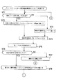
次に、電源制御方法に係る一連の工程について、図2及び図3に示すフローチャートを参照して説明する。
【0062】
このフローチャートに示される工程は、テレビジョン受像器のサービスレジストリが他の電子機器のサービスレジストリに、テレビジョン受像器に代わって検索処理を行う代行を委託する際の処理手順を示すものである。
【0063】
ここでは、テレビジョン受像機内のサービスモジュールが稼働中でないこと、また、ユーザレベルでのソフトウェアモジュールが稼働していないことを前提とする。
【0064】
この一連の工程は、テレビジョン受像器のサービスレジストリが、電源の停止状態の一具体例としての電源遮断準備のメッセージを受け取ることから開始される。すなわち、テレビジョン受像器のサービスレジストリが電源遮断準備のメッセージをパワーマネージャから受けることによりこの一連の工程が開始される。この電源切断準備のメッセージは、サービスレジストリが検索に対する代行をする契機となるものである。
【0065】
最初のステップS71においては、テレビジョン受像器のサービスレジストリが現在他ノードの電子機器の検索代行を行っているかどうかを確認する。
【0066】
他の電子機器の検索代行についての情報を保存しておくデータベースのデータ構造は、例えば図4のようなものになる。図中には、横方向に左から右に順に、“ノードID”、“属性情報のデータベースID”、“属性情報のバイト数”の列が並んでいる。図中の縦方向には、最初の行にはノードID“BB”、属性情報のデータベース“データベースB”、属性情報のバイト数“サイズB”が表示されている。これに続く行の表示は省略されている。この検索を行う属性情報に関するデータベースは、サービスレジストリの管理の下に、例えばクイリデータベースに保持される。
【0067】
このデータベースの内容を確認することにより、テレビジョン受像器のサービスレジストリが他の電子機器の代行をしているか否かを確認する。そして、テレビジョン受像器のサービスレジストリが他の電子機器のサービスレジストリの代行をしている場合には“YES”としてステップS72に進み、そうでない場合には“NO”としてステップS73に進む。
【0068】
ステップS72においては、上記図4に示したデータベースにエントリが存在すればその先頭のものから他の電子機器に代行を委託、すなわち再依頼する必要があるので、第1エントリのノードID“BB”の属性情報の代理依頼の対象とする。すなわち、このターゲットノードをBBとする。そして、ステップS74に進む。
【0069】
ステップS73においては、上記図4に示したデータベースにエントリが存在しないのでテレビジョン受像器の自己の属性情報だけを依頼すればよい。そこで、テレビジョン受像器のサービスレジストリは、自ノードのノードIDの属性情報を代理依頼の対象とする。そして、ステップS74に進む。例えば、自ノードのノードIDを“AA”とすると、ターゲットノードをAAに設定することになる。そして、ステップS74に進む。
【0070】
ステップS74においては、検索代行依頼をする属性情報のサイズと属するノードIDとをパラメータに含めて、検索代行依頼のメッセージを不特定の機器に対して発信するブロードキャストを行う。そして、ステップS75に進む。なお、このブロードキャストについては後に説明する。
【0071】
ここで、属性情報のサイズを知らせるのは、他のノードが検索代行を引き受ける場合にそのノードのRAM領域などに必要な属性情報を保存する余裕があるかどうかを判断するためである。
【0072】
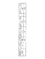
検索代行依頼のメッセージは、図5に示すようになる。すなわち、図中には、左から右に順に、“センダ(sender)ID”、“代行依頼識別ID”及び“代行依頼内容”の3個の行が表され、さらに“代行依頼内容”の欄は、“属性情報サイズ”及び“所属ノードID”の欄から構成されている。そして、センダID“XXXXXXXX”、代行依頼識別ID“2345”、属性情報サイズ“サイズB”、所属ノードID“BB”が、それぞれ表示されている。
【0073】
ステップS75においては、所定時間にわたって他のノードからの返事を待つために待機する。すなわち、上記ステップS74にてブロードキャストしたメッセージに対する他のノードからの応答を受け付ける。そして、次のステップS76に進む。
【0074】
ステップS76においては、上記ステップS75において他のノードから応答があったか否かによって分岐する。他のノードのサービスレジストリは、検索の代行をすることができない場合には応答しないので、何らかの応答があればそのサービスレジストリは代行を引き受ける用意があるということになる。返事があった場合には“YES”としてステップS78に進み、返事がなかった場合には“NO”としてステップS77に進む。
【0075】
なお、応答の際のパラメータとして属性情報を送る必要があるか否かを示すフラグが含まれることが変形例として考えられる。ノードによっては複数のノードに検索代行依頼を行っており、その場合にはデータを送る必要がないからである。
【0076】
また、変形例としては、ステップS76で属性情報が不要であるという応答があった場合には改めて検索依頼を行う必要はない。既に検索依頼を受けていることになるからである。
【0077】
ステップS77においては、所定の時間内に返事がなかった場合であり、検索代行を依頼する相手がいないことになるので依頼処理は失敗したことになる。この場合には、テレビジョン受像器のサービスレジストリは、検索に対して応答する必要があるので、CPUを止めるわけには行かない旨をパワーマネージャに伝える。そして、ステップS82に進む。なお、図2中の“▲2▼”は、図3中の“▲2▼”に手順がつながることを意味している。
【0078】
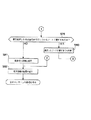
ステップS78においては、上記ステップS76で応答があったサービスレジストリに対して検索依頼を行うことになる。この際に送る属性情報は、所属するノードIDとそのノードのサービスモジュールに関して現在持っている全属性情報である。そして、ステップS79に進む。なお、図2中の“▲1▼”は、図3中の“▲1▼”に手順がつながることを意味している。
【0079】
ステップS79においては、テレビジョン受像器のサービスレジストリが現在処理したのは自分が代行しているノードに関するものであるという条件にしたがって分岐する。そして、現在処理したのは自分が代行しているノードに関するものであるときには“YES”としてステップS80に進み、そうでない場合には“NO”としてステップS81に進む。
【0080】
このステップS79においては、ここではステップS74からステップS78までの処理の対象がどのノードに係るものであるかの確認を対象となるノードを保持する変数であるターゲットノード(targetNode)の値を調べることにより行う。
【0081】
ステップS80においては、処理対象が自ノードの属性情報でなかった場合には代行依頼を受けていたノードに対して再依頼したことになり、既に代行する必要はなくなっているので、上記図4に示した検索を行う属性情報に関するデータベースから、対応するノードIDのエントリを削除する。その後ステップS71に戻り必要な依頼がすべて終わるか依頼できなくなるまで処理を繰り返す。ここで、自分が代行している全てのノードを終えると、ステップS73における自ノードに関する検索代行要求の工程に進むことになる。なお、図3中の“▲3▼”は、図2中の“▲3▼”に手順がつながることを意味している。
【0082】
一方、ステップS81においては、処理対象が自ノードの属性情報だった場合には全ての属性情報に対して依頼が終了したことになる。すなわち、検索代行依頼は成功したことになる。そして、次のステップS82に進む。
【0083】
ステップS82においては、テレビジョン受像器のサービスレジストリは、パワーマネージャに対して処理の成功又は失敗を通知する。処理が成功した場合には、パワーマネージャは電源を停止状態に制御するが、処理が失敗した場合にはCPUは稼働している必要があるので電源はオン状態に保たれる。
【0084】
そして、このステップS82にてこの一連の工程を終了し、次のメッセージの処理に移る。
【0085】
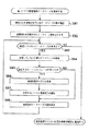
続いて、代理検索を受けているサービスレジストリの検索依頼受信時の一連の手順を、図6に示すフローチャートを参照して説明する。ここでは、テレビジョン受像器のサービスレジストリが、ビデオテープレコーダのサービスレジストリから、ビデオテープレコーダのオブジェクトであるサービスモジュールの属性情報を送られ、この属性情報についての応答を委託された場合を例示する。
【0086】
ビデオテープレコーダのサービスレジストリに代わって検索代行を引き受けたテレビジョン受像器のサービスレジストリは、自己のデータベース以外の属性情報データベースを有することになる。したがって、テレビジョン受像器のノードのみの検索の場合に加えて検索処理手順に幾分変更が必要になり、データベースに対する検索処理はデータベースの数だけ繰り返す必要がある。
【0087】
さらに、テレビジョン受像器のサービスレジストリは、依頼されているデータベースに該当するものが含まれている場合には、該当するノードに電源投入のメッセージを送る必要がある。
【0088】
この一連の工程は、テレビジョン受像器のサービスレジストリが、自己のノードの属性情報のデータベースを検索することにより開始される。
【0089】
最初のステップS91においては、上記図4に示した検索を行う検索情報に関するデータベースのエントリの数を確認する。ここでは、このデータベースにおいて、テレビジョン受像器に検索代行を依頼しているノードID“BB”等のエントリの数をNとする。そして、次のステップS92に進む。
【0090】
ステップS92においては、検索代行を依頼されているデータベースの数Nのうちで検索が終了したデータベースの数iを0に設定する。すなわち、i=0と初期設定する。そして、次のステップS93に進む。
【0091】
ステップS93においては、処理していない属性情報データベースが有るかどうか確認する。すなわち、検索処理が終了したデータベースの数iが検索を依頼されているデータベースの数Nより小さいという条件、i<Nによって分岐する。この条件を満たす場合には、未処理のデータベースが存在するので“YES”としてステップS94に進む。この条件を満足しない場合には全て処理済であるので“NO”として検索結果のリストのIDを検索依頼元に通知し、この一連の工程を終了する。
【0092】
ステップS94においては、上記図4に示したデータベースのエントリの内で現在の第i番目のデータベースの次のデータベース、すなわち第i+1番目のエントリのデータベースの属性情報データベースの中を検索する。そして、次のステップS95に進む。
【0093】
ステップS95においては、上記ステップS94において、該当するサービスモジュールが存在するという条件によって分岐する。そして、この条件を満たす場合にはステップS96に進む、この条件を満たさない場合にはステップS98に進む。
【0094】
ステップS96においては、ステップS94における該当するサービスモジュールをリストに追加する。この際、ステップS94の結果は別ノードでのサービスモジュールIDであるので、変換が必要となる。そして、次のステップS97に進む。
【0095】
ステップS97においては、検索に該当したことで、当該サービスモジュールが通信を受ける可能性が発生したので、テレビジョン受像器のサービスレジストリは、該当するノードに電源投入のメッセージを送る。そして、次のステップS98に進む。
【0096】
電源投入に成功すれば、上記ノードは自ら検索を受けることができるようになり、検索代行を依頼する必要がなくなるので、テレビジョン受像器のサービスレジストリは、上記図4に示した検索を行う属性情報に関するデータベースから当該ノードのエントリを削除し、さらに属性情報データベースも削除する。
【0097】
なお、この段階では上記該当したノードが通信を受けるかどうかはわからず、直ぐに検索代行の再依頼を受ける可能性があるので、検索を依頼されているデータベース削除を行わない変形例が挙げられる。
【0098】
ステップS98においては、処理済のデータベースの数iをインクリメントする。すなわち、i=i+1と設定する。そして、ステップS93に戻る。
【0099】
ここで、変形例としては複数のノードに属するサービスモジュールを一つのメッセージで通知できるように図7に示すような形式に変更することもできる。
【0100】
図中では、左から右に順に“検索識別ID”、“ノード数”、“ノードID”、及び複数の“該当モジュール数”の列を有している。そして、最初の行には、検索識別ID“1234”、ノード数“2”、ノードID“BB”、該当モジュール数“n”、該当モジュールID“B1”,・・・,該当モジュールID“Bn”が表示されている。次の行には、ノードID“CC”、該当モジュール数“m”、該当モジュールID“C1”,・・・,該当モジュールID“Cm”が、表示されている。
【0101】
このメッセージの形式を利用することにより、複数のノードに属するサービスモジュールに対して、一つのメッセージにて検索結果を通知することができる。
【0102】
続いて、電源制御方法の変形例について、図8に示すフローチャートを参照して説明する。
【0103】
他のノードからの検索結果を受け取った時点でサービスレジストリが他のノードの宛先のプロキシ(proxy )を作成する実装では、リストを使わなくなった時がプロキシを削除する適切なタイミングの候補であるので、通信が終了するまでサービスレジストリに対してリストが不要になった旨を通知する処理を行わないことにすることが考えられる。
【0104】
しかし、不必要にリストを保持してることはメモリの無駄であり、また、新しく他のノードからの検索結果が返ってきたときにリストの更新処理や、リスト変更のイベント処理などを行わなければならない。
【0105】
これらの無駄を避けるために、リストとが不要になったことを通知した際にプロキシを削除して良いか否かの判断材料として、実際に通信を行う予定の相手をサービスレジストリに通知してからリストとが不要になったことを通知し、全ての通信が終わった後に通信が終了したことを通知する実装が考えられる。
【0106】
この場合にはリストに含まれている宛先に対して通信を行う代わりに、通信相手をリストに含まれている宛先から選択し、その通信相手をサービスレジストリに通信するようにすることができる。
【0107】
この場合には、リスト全体が必要な工程と、リストに含まれていたいくつかの宛先が必要な工程に分けることができる。この実装では通信する予定であることが知らされていない宛先のプロキシはリストが不要になった際に削除し、通信予定が知らされている宛先のプロキシは通信が終了したことを通知した際に削除されることになる。通信予定の宛先の個数には制限はない。
【0108】
この一連の工程は、ネットワーク中の他のサービスモジュールとの通信が必要になることにより開始される。
【0109】
最初のステップS101においては、同一ノードのサービスレジストリに対して検索要求のメッセージを送り、次のステップS102においてはサービスレジストリからの検索結果を待ち、これに続くステップS103においては、サービスレジストリの検索結果を含むリストのIDを受け取る。そして、次のステップS104に進む。
【0110】
ステップS104においては、リストに含まれている宛先の数が0であるという条件によって分岐する。すなわち、リストに含まれている宛先の数が0の場合には“YES”としてステップS107に進み、そうでない場合には“NO”としてステップS105に進む。
【0111】
ステップS105においては、通信相手をリストに含まれている宛先から選択する。次のステップS106においては、通信相手をサービスレジストリに通知する。そして、これに続くステップS107に進む。
【0112】
ステップS107においては、サービスレジストリに対して、リストが不必要になったことを通知する。そして、次のステップS108においては通信相手との通信が必要な処理を行い、これに続くステップS109においては通信が終了したことをサービスレジストリに通知する。そして、この通信が必要な処理に係る一連の工程を終了する。
【0113】
以上のような手順により、実際に通信を行う相手をサービスレジストリに通知することにより、作業の効率化を図っている。
【0114】
続いて、電源制御方法の具体例として、ビデオテープレコーダにおいて、再生ボタンの押圧というイベントに発生により開始される一連の工程について、図9及び図10に示すフローチャートを参照して説明する。
【0115】
この具体例においては、単純な例として家の中の各AV機器がデジタルネットワークに接続されており、データの配信などは全てソフトウェアで操作できる状態を考える。このネットワークには、テレビジョン受像器及びビデオテープレコーダが接続されている。
【0116】
この一連の工程は、ネットワークに接続する機器のサービスモジュール間の通信が必要になる一例であり、ユーザがビデオテープをビデオテープレコーダに挿入し、再生ボタンを押圧することにより開始されるものである。すなわち、この一連の工程は、ビデオテープレコーダの再生ボタンの押圧というイベントの発生により開始される。
【0117】
最初のステップS111においては、ネットワーク内でサービスモジュールタイプがディスプレイの構成要素を含む機器を検索する。そして、これに続くステップS112に進む。
【0118】
ステップS112においては、処理が終了したデータベースの数を表す変数Iが0に設定される。そして、次のステップS113に進む。
【0119】
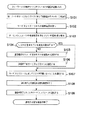
ステップS113においては、処理していない検索結果があるという条件によって分岐する。すなわち、処理すべきデータベースの数をNとすると、N>Iを満たす場合には処理していない検索結果が残っているので“YES”としてステップS114に進み、この条件を満足しない場合には検索処理を終了したので“NO”としてステップS122に進む。なお、図9中の“▲2▼”は、図10中の“▲2▼”に手順がつながることを意味している。
【0120】
ステップS114においては、未処理の最初の要素について処理を行う。ここれ、処理を行ったデータベースの数はIであるので、未処理の最初のデータベースである第I+1番目のデータベースについて処理を行う。そして、このデータベースの処理が終わると、処理の終わったデータベースの数を表す変数であるIをインクリメントしてI=I+1とする。そして、ステップS115に進む。
【0121】
ステップS115においては、ディスプレイが使用中であるという条件によって分岐する。すなわち、この条件を満足する場合には“YES”としてステップS113に戻り、この条件を満足しない場合には“NO”として次のステップS116に進む。
【0122】
ステップS116においては、ディスプレイに使用要求を出し、ステップS117に進む。
【0123】
ステップS117においては、ステップS116におけるディスプレイに対する使用要求が受け入れられたか否かによって分岐する。すなわち、上記要求が受け入れられた場合には“YES”としてステップS118に進み、この要求が受け入れられなかったときには“NO”として上記ステップS113に戻る。
【0124】
ステップS118においては、ディスプレイを含む機器がスピーカを含むか否かによって分岐する。すなわち、ディスプレイを含む機器がスピーカを含む場合には“YES”としてステップS120に進み、その機器がスピーカを含まない場合には“NO”としてステップS112に進む。ここで、図9中の“▲1▼”は、図10中の“▲1▼”に手順がつながることを示している。
【0125】
ステップS120においては、スピーカの使用要求を出し、次のステップS121に進む。
【0126】
ステップS121においては、上記ステップS120の要求が受け入れられたか否かによって分岐する。すなわち、スピーカの使用要求が受け入れられたときには“YES”としてこの一連の工程を終了する。スピーカの使用要求が受け入れられなかったときには“NO”としてステップS122に進む。
【0127】
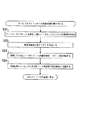
ステップS122においては、ネットワーク内でサービスモジュールタイプがスピーカの構成要素を含む機器を検索する。そして、次のステップS123に進む。
【0128】
ステップS123においては、検索が終了したデータベースの数を表す変数Iを0に設定する。そして、これに続くステップS124に進む。
【0129】
ステップ124においては、処理していない検索結果があるか否かによって分岐する。処理すべきデータベースの数Nとすると、処理していない検索結果があるとき、すなわちN>Iを満足するときには“YES”としてステップS125に進み、検索を終了してN>Iを満足しないときには“NO”としてこの一連の処理を終了する。
【0130】
ステップS125においては、データベースの最初の要素について処理を行う。すなわち、処理が終了した数を表す変数Iの次の第I+1番目のデータベースについて処理が行われる。この処理が終了すると、上記変数はI=I+1とインクリメントされる。そして、これに続くステップS126に進む。
【0131】
ステップS126においては、スピーカが使用中であるという条件によって分岐する。スピーカが使用中であるときには“YES”として上記ステップS124に戻り、使用中でないときには“NO”として次のステップS127に進む。
【0132】
ステップS127においては、スピーカに使用要求を出し、ステップS128に進む。
【0133】
ステップS128においては、ステップS127にてスピーカ出した使用要求が受け入れられたか否かによって分岐する。すなわち、上記要求が受け入れられた場合には“YES”としてステップS129に進み、使用要求が受け入れられなかった場合には“NO”として上記ステップS124に戻る。
【0134】
ステップS129においては、再生を開始し映像信号をディスプレイに、音声信号をスピーカに送る。そして、この一連の工程を終了する。
【0135】
ここで、上記S113やS124において未処理の検索結果がない場合には、エラーが発生したことを示して処理を中断することも考えられる。この場合エラーメッセージの表示先としてはビデオテープレコーダの備える液晶パネルやエラーランプ等の表示装置だけではなく、ネットワーク制御用の端末に表示することの考えられる。
【0136】
アナログの通信線での直接の接続を含む場合には、その部分の制御を行うソフトウェアモジュールを作成し、ユーザが接続情報を入力することにより対応することができる。このためには入力装置と表示装置とを備えた機器がネットワーク中に含まれていることが必要となる。
【0137】
以上述べたように、電源制御方法は、単数又は複数のオブジェクトのサービスモジュールの属性情報を取得する属性情報取得工程と、この属性情報取得工程にて取得した属性情報を他の電子機器の備えるサービスレジストリに送出して外部からの上記属性情報についての照会に対する応答を委託してから電源を停止状態にする属性情報管理工程とを有している。
【0138】
また、電源制御方法は、単数又は複数のオブジェクトのサービスモジュールの属性情報を取得し、他の電子機器から委託された場合には上記他の電子機器のオブジェクトのサービスモジュールの属性情報をも併せて取得する属性情報取得工程と、上記属性情報取得工程にて取得した属性情報について、上記他の電子機器から委託された場合には上記他の電子機器のオブジェクトのサービスモジュールの属性情報についても、外部からの照会に応答する属性情報管理工程とを有するものである。
【0139】
次に、電子機器の備えるサービスレジストリ及びサービスモジュールにおける通信について説明する。
電子機器の備える各サービスモジュールは、メッセージを送ることによって処理依頼等の協調動作を実現する構成である。
【0140】
ここで、サービスモジュール間の情報伝達の手段としては、メッセージキューを用いた1対1の通信と、送り手側は特定の聞き手を意識しないイベントを用いた通信が各ノード内で供給されているものとする。
【0141】
ここでいうサービスモジュールとは、ある機能を実現するための装置だけでなく、メモリに格納されCPUで実行されるプログラムも含む。
【0142】
サービスモジュールがプログラムの場合には、全体の実行手段を示したものではなく、各機能を実現するためのサービスモジュール毎の動作を記述したオブジェクト指向的なモデルを用いて説明する。同一CPU上のタイムシェアリングや複数CPUを使った並列処理や分散処理などが行われている場合にはサービスモジュールの処理は並列実行されているものとみなす。
【0143】
各ノードの電子機器には一般に複数のサービスモジュールが備えられ、複数ノードがネットワークにて接続されているが本発明の想定している状況である。
【0144】
まず、基本となるノードに電源が入っている状態での検索の手順を示す。ある特定の機能もしくは属性を持つサービスモジュールと通信を行いたいサービスモジュールは同一ノード内のサービスレジストリに対して検索要求のメッセージを送る。
【0145】
検索要求を受けたサービスレジストリは管理しているサービスモジュールに関する情報を利用して検索に該当するものが自分と同じノード内に存在するかどうかのチェックをする。同時にノード内からの検索を受けたサービスレジストリはブロードキャストマネージャに依頼して検索要求をネットワーク全体に流す。
【0146】
ネットワークからの検索要求のブロードキャストメッセージを受けた各ノードのブロードキャストマネージャはそれぞれのノード内のサービスレジストリに検索要求を配送する。ノード外からの検索要求を受けたサービスレジストリは、ノード内からの検索を受けた場合と同様に管理している情報を利用して検索に該当するものが自分と同じノード内に存在するかどうかのチェックをする。ノード外からの検索要求に該当するものが自ノード内に存在した場合には、検索要求元のサービスレジストリに対して結果を通知する。
【0147】
ノード内からの検索要求を受けたサービスレジストリは、ネットワークを介して他のサービスレジストリからの結果を待ちながら、自分自身の検索結果を基にしたリストを作成し、他のサービスレジストリからの結果が返ってきた場合には順次リストに追加する。ノード内からの検索要求を受けたサービスレジストリは自分自身の検索結果を作成後、指定された時間が経過した後に検索要求リストのIDを知らせる。この指定された時間は、0のことも有り得る。
【0148】
検索要求元はサービスレジストリから返ってきたリストの内容を確認し、そこに含まれているサービスレジストリのメールボックスに対して通信を行うことによって処理依頼等を行う。検索要求元にとって知らされたリストが不要となった時点で、もう使わないことを示すメッセージをサービスレジストリに送り、サービスレジストリは該当するリストを削除し、それ以降に他のノードから返ってくるそのリストに対する検索結果は捨てることになる。
【0149】
リストIDを検索要求元に知らせた後、削除する前に他のノードからの検索結果がサービスレジストリに返ってきた場合には、該当するリストの内容を追加し、リスト内容が更新されたことを示すイベントを発生させることにより、検索元がイベントをチェックしていれば対応が可能になる。
【0150】
続いて、各サービスモジュールごとの処理をフローチャートを参照して説明する。
【0151】
基本的な流れとして、最初にサービスレジストリを利用するサービスモジュールの処理、次にサービスモジュールからの検索要求を受けたサービスレジストリの処理を示し、最後に他のノードのサービスレジストリからの検索要求を受けたサービスレジストリの処理を示す。
【0152】
その後、他のノードのサービスレジストリに転送した検索結果が返ってきた時のサービスレジストリの対応と、サービスレジストリからの結果を処理中に検索結果に追加があった場合のサービスモジュールの処理方法、検索結果が不用になった際の処理を示してから、他のノードのサービスレジストリの代理依頼に関して説明する。
【0153】
まず、他のサービスモジュールとの通信を行うためにサービスレジストリを使う際の一連の工程を、図11に示すフローチャートを参照して説明する。
【0154】
この一連の工程は、ネットワーク中の他のサービスモジュールとの通信が必要になることから開始される。すなわち、このネットワーク中に特定の機能を有するサービスモジュール、もしくは特定の機能を提供するソフトウエアモジュールを利用する必要が生じると開始される。
【0155】
最初のステップS11においては、同一ノードのサービスレジストリに対して検索要求のメッセージを送る。すなわち、同一のノード内のサービスレジストリに対して、通信を行いたい相手の種別や属性情報、位置情報等を含む検索要求を送る。そして、次のステップS12に進む。
【0156】
ステップS12においては、サービスレジストリからの検索結果が返ってくるまで待機する。並列処理が行える環境であれば、検索結果を待つ間にそれとは関係のない処理を行ってもよい。そして、ステップS13に進む。
【0157】
ステップS13においては、サービスレジストリの検索結果を含む例えばリスト番号のようなリストのIDを受け取る。オブジェクト指向的なモデルを使用すれば、ここで受け取るのはリストを表現するオブジェクトと通信を行う際の宛先であり、検索結果である検索要求に合致する通信相手と通信を行うための宛先や要求を満たす通信相手の数はリストとの通信によって得ることになる。ただし、実装上は通信相手の宛先を含む配列データのメモリ上のアドレス等の直接的なデータを受け取ることも考えられる。そして、次のステップS14に進む。
【0158】
ステップS14においては、リストに含まれている宛先の数を確認する。すなわちリストに含まれている宛先の数が0であるという条件によって分岐する。この宛先の数が0の場合には必要とする通信相手がいないことがわかるので、“YES”としてサービスレジストリに対してリストが不用になったことを通知するステップS16に進み通信相手がいない場合の処理に移る。そうでない場合には“NO”として次のステップS15に進む。
【0159】
ステップS15においては、リストに含まれている宛先の数が0以外であるので、そのリスト中の宛先と通信を行う。例えば、家の中のAV機器のネットワーク上で、ビデオテープレコーダが表示先のディスプレイを探していた場合であれば、検索結果の中から使用されていないものを一つ選択するまで通信を行うことになるし、テレビがチャンネルリストを表示しようとしているのであれば、利用可能な全てのチューナに対して通信を行うことになる。いずれにせよ、リストをどのように利用するかは検索元の自由であり、サービスレジストリは関知しない。そして、次のステップS16に進む。
【0160】
ステップS16においては、サービスレジストリに対してリストが不用になったことを通知する。この時に不要なリストを特定するための識別情報として上記ステップS15で、サービスレジストリから受け取ったものを利用する。サービスレジストリはこの情報により検索要求を特定し、必要な処理を行う。そして、この通信が必要な処理に係る一連の工程を終了する。
【0161】
なお、この一連の処理は必ずしも通信相手との通信が全て終わった後である必要はない。例えばステップS16においてビデオテープレコーダがディスプレイを探している例では使用中でないディスプレイを見つける処理が終了すれば、その後は検索結果であるディスプレイのリストは不要なので、その時点でこの処理を行っても問題ない。
【0162】
続いて、上記ステップS11で送られた検索依頼を受けたサービスレジストリに係る一連の工程について、図12に示すフローチャートを参照して説明する。この一連の工程は、同一ノード内のサービスモジュールからの検索依頼を受け付けることから開始される。
【0163】
最初のステップS21においては、ブロードキャストマネージャを利用して他ノードのサービスレジストリに検索要求を送る。すなわち、受け付けた検索要求を他のノードのサービスレジストリに対してブロードキャストするために、ブロードキャストマネージャに依頼する。これは通常のサービスモジュールがネットワークを意識する必要がないようにするためのモデルであり、ブロードキャストマネージャとサービスレジストリの双方の機能を兼ねるサービスモジュールとして実装することもできる。
【0164】
この際ブロードキャストする内容としては、検索要求の他にブロードキャストのヘッダとして、ブロードキャスト元のノードを特定するIDとサービスレジストリ宛ての検索要求であることを示すID、返事をする際に対応する検索要求を特定するための検索識別IDが含まれる。そして、次のステップS22に進む。
【0165】
ステップS22においては、検索元に結果を特定するためのリスト等のIDを用意する。このIDに対応して、配列等のデータ構造を作成することになる。
【0166】
後にステップS21で送った検索要求に対するノードから返ってきた際にこのデータ構造に追加する必要があるため、ステップS21で送った検索識別IDとここで用意したデータ構造のIDとの対応関係を記録しておく。そして、ステップS23に進む。
【0167】
ここで、IDは実装する際のプログラム言語やOSに依存するが、オブジェクトIDやメモリのアドレス、サービスレジストリが管理するID等を用いることになる。
【0168】
ステップS23においては、自ノードのサービスモジュールに関してのデータベースである属性データベースを検索し、検索要求に合うサービスモジュールのIDをステップS22で用意したデータ構造に追加する。この段階では検索結果は同一ノード内に存在するサービスモジュールだけからなる。そして、ステップS24に進む。
【0169】
ステップS24においては、検索元にステップS22で用意したIDを通知する。このIDは同一ノード内でのみ参照されるので、どのような形式のものであってもノード内でのみ整合性が取れていればよい。そして、サービスモジュールからの検索依頼に対する処理を行うこの一連の工程を終了し、次のメッセージの処理に移る。
【0170】
実際には一連の検索処理としてはステップS21においてブロードキャストした検索に対する応答が返ってきた段階で更に処理を行うことになるが、それは別のメッセージに対する処理として扱う。
【0171】
続いて、上記ステップS21でブロードキャストされた他のノードからのサービスレジストリからの検索要求を受けたサービスレジストリについての一連の工程を、図13に示すフローチャートを参照して説明をする。
【0172】
この一連の工程は、基本的には上述した自ノードのサービスモジュールからの検索依頼を受けたときの処理と同じであるが、上記ステップS21におけるブロードキャストを行わないことと、検索結果をノード間通信で伝えるためにリストのIDだけでなく内容まで通知する点が異なる。
【0173】
この一連の工程は、他のノードのサービスレジストリからの検索要求を受け付けることから開始される。最初のステップS31においては、検索元に返す情報を格納するためのデータ構造としてリストや配列などを用意する。
【0174】
ステップS31においては、検索要求元に返すリストを作成する。これに続くステップS32においては、自ノードのサービスモジュールに関してデータベースを検索し、検索要求に合うサービスモジュールのIDをステップS31で用意したデータ構造に追加する。検索結果は同一ノード内に存在するサービスモジュールだけからなる。そして、ステップS33に進む。
【0175】
ステップS33においては、元のノードにステップS32で検索した結果であるサービスモジュールのIDのリストを通知する。上述の場合と違い、ステップS32で用意したデータ構造全体を示すものではなく、リストに含まれる個々の要素と要素の個数を通知する。結果を通知する際には、検索結果の他にどの検索要求に対するものかを示すための検索識別IDも同時に通知する。
【0176】
ここで内容を全て通知するのは後にノード間通信を行って要素の確認を行ったりすることを省略するためであり、リストが不要になったときに破棄するタイミングをノード内で判断できるようにするためでもある。なお、変形例としてはデータ構造のIDだけを通知することも考えられる。
【0177】
しかし、上記ステップS24でデータ構造のIDだけを通知したのは、後に他のノードからの検索結果が図中の処理の結果として返ってきて内容が追加されたときに、変化があったことを知らせるためのIDとしてであるが、このステップS33で通知するのはあくまでもこのノード分の結果であり、後に変更する必要がないので、内容を通知しても何の問題もない。
【0178】
いずれにせよ、ここで通知するサービスモジュールのIDは別のノードで処理されるため、ネットワーク内でビット数が規定されている必要がある。これは各ノードで任意のIDを用いることができた上述の場合との大きな違いとなる。
【0179】
ステップS34においては、ステップS31で作成しステップS32で要素を追加したデータ構造はもはや不要であるので破棄する。なお、ステップS34の変形例としてデータ構造のIDだけを通知する場合には、この処理はこの時点では行えず、リスト破棄要求のメッセージを受けた際に行うことになるが、利用中にノードがネットワークから切断されたような場合に無駄なデータを破棄するための追加処理が必要になる。
【0180】
このステップS34において、他ノードのサービスレジストリからの検索要求に対する一連の工程を終了し、次のメッセージの処理に移る。
【0181】
続いて、上記ステップS33において通知した検索結果を受け取ったサービスレジストリにおける一連の工程を、図14に示すフローチャートを参照して説明する。
【0182】
この一連の工程は、他ノードのサービスレジストリからの検索結果のメッセージを受信することから開始される。このメッセージには上記ステップS21にてブロードキャストする際に付加しておいた検索識別IDと、検索内容に合致するサービスレジストリのIDのリストや個数が含まれている。
【0183】
最初のステップS41においては、上記図12中のステップS22で用意しておいた記録を用い、検索識別IDに対応するデータ構造のIDを特定し、それが使用中であるかを確認する。ここで使用中というのは、上記図11中のステップS16のリスト不要通知を受けていないことを意味する。
【0184】
検索識別IDに対応するリストが使用中の場合には、“YES”としてステップS42以降の処理を行うが、既にリスト不要通知を受けている場合には他ノードの検索結果も不要なので“NO”としてこの一連の工程を終了する。
【0185】
ステップS42においては、ステップS41で確認したデータ構造に対し、受け取った検索結果に含まれるサービスモジュールのIDリストを追加する。そして、次のステップS43に進む。
【0186】
ステップS43においては、イベントマネージャに対してデータ構造の内容に変更が生じたことを示すイベントを通知することにより、そのデータ構造に関心を持っているサービスモジュールが処理を行うための機会を提供する。このイベントのパラメータとしてはステップS42で変更したデータ構造のIDが含まれる。これにて、この一連の工程を終了し、次のメッセージの処理に移る。
【0187】
なお、ステップS43においてはイベントマネージャを利用したが、サービスレジストリ自体が検索元のデータを記録しておき1対1通信によって通知するような変形例も可能である。
【0188】
また、検索結果の要素数が0の場合には変化は生じていないので、ステップS43の通知は行う必要がないのでその確認を行うことも考えられる。ただし、要素数の変化があったかどうかは利用側で確認することも可能であるし、要素数0の場合にはそもそも検索結果を通知しない変形例も考えられ、その場合には確認は必須ではないので上記フローチャートには含めていない。
【0189】
さらに、上記図13中のステップS32とステップS33の間に所定の時間だけ他ノードからの返事を待ち、一度検索元に検索結果を通知した後は追加処理は行わないという変形例も考えられる。この場合ステップS41における使用中とは返答待ち期間中のことになり、ステップS43は不要になる。
【0190】
ステップS43により、検索結果に変更があった場合に検索依頼元が行う処理は多様であり、状況によって異なるのでフローチャートとして示すことはできない。例えば、先に言及したように使用中でないディスプレイを探すのが目的であれば既に見付けている場合には何の処理も必要ないし、見つかっていない場合には追加されたものに対するチェックを行うことになる。また、全てのチューナーが提供できるチャンネル一覧を表示するのが目的であれば追加されたチューナーのチャンネル情報を得るべく通信することになる。
【0191】
続いて、検索結果変更のイベントを受けた際の検索依頼元についての一連の工程を、図15に示すフローチャートを参照して説明する。
【0192】
この一連の工程は、検索結果変更のイベント通知を受けることにより開始される。すなわち、上記図14中のステップS43でサービスレジストリがイベントマネージャを利用した結果としてイベント通知を受ける。もしくはサービスレジストリから直接メッセージで通知される。
【0193】
イベントマネージャを使用する実装の場合には、この通知を受けるためには上記図11中のステップS14までにイベントマネージャに検索結果変更イベントに対して興味があることを知らせておく必要がある。
【0194】
最初のステップS51においては、変更のあったデータ構造のIDが自分の使用中のものかどうかを確認する。これは主にイベント通知の場合にはイベントの種類だけで判断され、関係のないものに関しても通知される可能性があるからである。サービスレジストリから直接通知される場合でもミスを避けるために確認して損はないが必須ではない。
【0195】
そして、データ構造のIDが使用中のものであるときには“YES”としてステップS52に進み、そうでないときには“NO”としてこの一連の工程を終了して次のメッセージの処理に移る。
【0196】
ステップS52においては、上述の通り、状況に応じて必要な処理がなされる。そして、この一連の工程を終了し、次のメッセージの処理に移る。
【0197】
続いて、上記図11中のステップS16におけるリストの不要通知を受信したサービスレジストリについての一連の工程を、図16に示すフローチャートを参照して説明する。
【0198】
この一連の工程は、上記ステップS16で検索依頼元が送ったリスト不要通知をサービスレジストリが受け取ることにより開始される。上記リストには、メッセージのパラメータとしてリストとを特定するためのIDが含まれている。
【0199】
最初のステップS61においては、リストのIDに対して不使用であることを示す情報を記憶する。これは他のノードのサービスレジストリからの検索結果がいつ返ってくるか分からない状況においてステップS41での判断に使われることになる。ここで、情報の記憶の仕方としては例えばIDに対して不使用フラグを立てることが考えられる。そして、次のステップS62に進む。
【0200】
ステップS62においては、リスト自体を破棄する。変形例としてはリストを破棄することはせず、複数のリストをプールしておき再利用することが考えられる。この場合には同一のオブジェクトIDやメモリのアドレスを再利用するため、リストのIDはサービスレジストリが管理するものになり、ここではリストの内容を空にする処理が行われる。そして、この一連の処理を終了し、次のメッセージの処理に移行する。
【0201】
変形例としてはIDに対応するリストが存在しない場合には不使用と判断することによってステップS61を省略し、ステップS62だけを行うことが考えられる。
【0202】
次に、通信路上で検索要求等のメッセージのデータ形式や、各サービスレジストリが扱うデータ形式について説明をする。様々な変形例が考えられるが基本的に必要な情報の一例を示す。
【0203】
単純な例として属性名と属性として任意の文字列を持つ形で各サービスモジュール情報を持ち、図17の形式で属性情報を保持する場合において、複数の属性を一つのサービスモジュールに対して与えたい場合には複数のエントリを持つことになる。
【0204】
このサービスレジストリの持つサービスモジュールのデータベースの第1の例においては、図中横方向には、左から右に順に“モジュールID”、“属性名”及び“属性”の3つの列を有し、図中縦方向には、モジュールID“1”に対して属性名“モジュールタイプ”及び属性“ブロードキャストマネージャ”が、モジュールID“2”に対して属性名“モジュールタイプ”及び属性“イベントマネージャ”が、モジュールID“4”に対して属性名“モジュールタイプ”及び属性“ネットワークマネージャ”が、モジュールID“11”に対しては属性名“モジュールタイプ”及び属性“ディスプレイ”がそれぞれ対応して表示されている。
【0205】
ここでモジュールIDとは、ノード内での識別に使われるものであり、メッセージの宛先としても使われることになる。
【0206】
予め幾つかの属性を持つことを仮定して、例えばタイプや表示するための名前は必ず持ち、任意個数の追加属性を持ってもよい場合であれば図18のような形式になる。
【0207】
このサービスレジストリの持つサービスモジュールのデータベースの第2の例には、左から右に、順に“モジュールID”、“モジュールタイプ”、“モジュールネーム”、“属性数”、“属性数1”及び“属性1”の6個の列を有し、図中縦方向には、モジュールID“1”に対してモジュールタイプ“1”、モジュールネーム“ブロードキャストマネージャ”及び属性数“0”が、モジュールID“2”に対してモジュールタイプ“2”、モジュールネーム“イベントマネージャ”及び属性数“0”が、モジュールID“4”に対してモジュールタイプ“3”、モジュールネーム“ネットワークメッセンジャ”及び属性数“0”が、モジュールID“11”に対してモジュールタイプ“100”、モジュールネーム“D−001”、属性数“1”、属性名1“サイズ”及び属性1“21”がそれぞれ対応して表示されている。
【0208】
この場合、持つことが決まっている属性に対して予め数字に意味を割り振ることにより、文字列を記憶するのに比べ記憶領域を減らすことも考えられる。図中においては、モジュールタイプに関して例えば“100”がディスプレイを示すことにより上記図11の場合と同様の情報を少ないバイト数で保持していることになる。
【0209】
この例ではディスプレイである“D−001”は1個の追加属性を持ちそれは“サイズ”であるが、他のサービスモジュールは追加属性は持っていない。仮に“D−001”が“b/w”か“カラー”かを示す“カラー”という属性も持つとすれば、属性数は“2”になることになる。
【0210】
このようにあるタイプのサービスモジュールに関しては、図19に示すように、一般的な属性に対しても予め属性タイプを数値で定義しておくことによって記憶領域を更に減らす変形例も考えられる。
【0211】
このサービスレジストリが持つサービスモジュールのデータベースの第3の例においては、左から右に、順に“モジュールID”、“モジュールタイプ”、“モジュールネーム”、“属性数”、“属性タイプ”、“属性名”及び“属性”の7個の列を有し、図中の縦方向には、モジュールID“1”に対してモジュールタイプ“1”、モジュールネーム“ブロードキャストマネージャ”及び属性数“0”が、モジュールID“2”に対してモジュールタイプ“2”、モジュールネーム“イベントマネージャ”及び属性数“0”が、モジュールID“4”に対してモジュールタイプ“3”、モジュールネーム“ネットワークメッセンジャ”及び属性数“0”が、モジュールID“11”に対してモジュールタイプ“100”、モジュールネーム“D−001”、属性数“3”、属性名タイプ“101”及び属性“21”が、次の行には属性タイプ“102”及び属性“カラー”が、その次の行には属性タイプ“0”、属性名“サウンド”及び属性“ステレオ”がそれぞれ表示されている。
【0212】
図中においては、属性タイプが“0”の場合には未定義のタイプであり、属性名で区別する必要がある例を示している。この例においては属性タイプの“101”は、サイズを意味し、“102”はカラーを意味している。モジュールタイプの“100”は図12と同様にディスプレイを意味している。複数の追加属性を持つモジュラーの場合には続く属性数の後に可変長の属性データが続くことになる。
【0213】
この例では属性自体は全て文字列になっているが、属性タイプとして文字列以外の数値データであることを示すようなフラグを付加することによって属性として数値、例えば、整数、浮動小数点、ブーリアン、列挙型等をとることもできるようにする変形例も考えられる。
【0214】
上記図12のフローチャートの入り口となる検索依頼メッセージのデータ形式はサービスレジストリの持つデータベースとどの程度複雑な検索を指定できるようにするかで変わってくるが、例えば上記図17のデータベースに対して単純な検索だけを行う場合には図20のようになる。
【0215】
図中には、横方向に左から右に“検索属性名”及び“検索属性”の2つの列を有し、それぞれに対応して、検索属性名“モジュールタイプ”及び検査属性“ディスプレイ”がそれぞれ表示されている。
【0216】
この場合の文字列の表現形式はノード内部の処理系によって異なって構わない。例えば、先頭にバイト数を示すパスカル形式や文字列の終端を示すデータを付加するCやC++形式等がある。
【0217】
上記図17に示したサービスモジュールのデータベースの第1の例においては、属性名と属性は常に文字列であることがわかっているのでこのような検索依頼にて十分であるが、上記図18に示した第2の例又は図19に示した第3の例のように、デは文字列以外のデータが含まれていることもある。したがって検索依頼自体にその情報が含まれている必要がある。
【0218】
そこで、文字列以外の情報を含む検索依頼のメッセージのデータ形式を、図21に示す。図中には、左から右に“検索属性タイプ”、“検索属性名”及び“検索属性”の3個の列を有し、これらに対応して、“検索属性タイプ“101”及び検索属性“21”がそれぞれ示されている。なお、検索属性名に対応する欄は空欄になっている。
【0219】
ここで、検索属性では上記図19に示したデータベース内の属性IDと同じものである。検索属性名は同図の例であれば検索属性タイプが0の場合のみ指定されることになる。
【0220】
またデータベースの例としては図示していない検索属性に文字列以外のものを許すような変形例の場合には、検索属性が文字列なのか数字なのかを示すための属性タイプ情報を追加する必要がある。各データ型を示す数値を予め割り当てておくのが効率的であるが、拡張性を考慮して文字列を使うような変形例も有り得る。
【0221】
検索依頼の変形例としては、AND,OR,NOTのような論理演算を含む複雑な検索を行えるようにすること、特定のノード内のみ、指定したグループに属するノード内のみ等の検索範囲を指定した検索を行えるようにすること等があるが、ここでの説明は省略する。
【0222】
上記図12に示した一連の工程において、S21の前のステップでサービスモジュールから検索依頼を受けたサービスレジストリが図19に示したようなデータベースを持っていた場合に、ステップS22で作られる検索結果は例えば図22のようになる。
【0223】
すなわち、この検索結果リストは、図中の左から右に、順に“該当モジュール数”、“該当モジュールID1”の列を有している。そして、図中には、該当モジュール数“1”及び該当モジュールID“11”がそれぞれ示されている。なお、該当モジュールIDの欄は、複数個あってもよい。
【0224】
ステップS24で検索依頼元に通知されるのはこの検索結果全体を示す、例えば“201”のようなリストのIDだけであり、検索に該当したサービスモジュールである“11”ではない。
【0225】
一方、ステップS22で他のノードのサービスレジストリにブロードキャストするメッセージは図23のようになる。
【0226】
図中には、左から右に、順に“センダ(sender)ID”、“検索識別”、“検索内容”の欄を有し、さらに上記“検索内容”の欄は、“検索属性ID”、“検索属性名”及び“検索属性”の欄を有している。そして、センダID“XXXXXXXX”、検索識別ID“1234”、検索属性ID“101”及び検索属性“21”がそれぞれ表示されている。
【0227】
この図に示したのはブロードキャストマネージャにブロードキャストするように依頼する内容であり、ネットワークに流れるときにはにはブロードキャストマネージャがヘッダを付加することになる。上述したように、このヘッダには送信元のノードIDやブロードキャストID等が含まれている。
【0228】
ブロードキャストに対して結果を送り返す際にノードIDとノード内でのモジュールIDが必要になるので、ノード内でのサービスレジストリのモジュールIDであるセンダIDが図中に含まれている。
【0229】
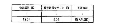
図中のメッセージに対する応答が返ってきた時点で検索識別IDに応じてどのリストに対して処理をすればいいのかを覚えていく必要がある(上記図14中のステップS41で参照される)が、そのためのデータは例えば図24のようになる。
【0230】
すなわち、図中には、左から右に、順に“検索識別ID”、“検索結果のリストID”及び“不要通知”の3個の欄を有し、検索識別ID“1234”に対して検索結果のリストID“201”及び不要通知“0(FALSE)”がそれぞれ表されている。
【0231】
新しい検索識別IDに対するエントリはステップS21をブロードキャスト依頼した時点で用意され、ステップS22で用意される検索結果のIDが記憶されることになる。
【0232】
上記図14の処理が始まる前にデータベースが更新されていればいいので、実際にエントリーを追加するタイミングは図12に示したフローチャートの中であれば何処でもよい。
【0233】
ただし、サービスレジストリ相互の通信の処理に関しては高い優先度を持たせるような変形例の場合には、上記図12中でステップS21でブロードキャストを依頼する前にステップS22を実行し、データベースの更新を終了しておくことが誤動作を防ぐ上では重要になる。
【0234】
上記図23のメッセージを受け取ったサービスレジストリの処理は上記図13に示してある取りであり、内部的に作成する検索結果は上記図22と同様である。ここで出てくる新しいデータ形式としては、上記図13中のステップS33で送る検索結果がリスト全体を示すIDではなく、内容を含むものであるために通信線を流れる図25に示す形式のものがある。
【0235】
同図のメッセージはブロードキャストではなく、1対1の通信としてブロードキャスト元のノードのサービスレジストリ宛てに送られる。例えばノードID“AA”のブロードキャスト元のモジュールID“XXXXXXXX”のサービスレジストリ宛てに送られる。
【0236】
この結果に含まれている“B1”から“Bn”までのモジュールIDはサービスモジュールが属しているノード“BB”の中でのモジュールIDであり、それ以外のノードにとっては意味は分からない只の数字であるが、ノード“BB”宛てのメッセージのヘッダにノード内部での宛先として指定しておくことにより、ノード“BB”のメッセンジャがメッセージの本体をそのサービスモジュールに届けることが保証されている。
【0237】
これはサービスレジストリがブロードキャストする際に返答先としてノード内のモジュールIDとして指定していた“XXXXXXXX”に関しても同様で他のノードは“XXXXXXXX”が何を意味するかを知る必要はない。
【0238】
ただし、ネットワークに接続されている全てのノードが同様に扱う必要があるので、このモジュールIDのビット長だけは例えば64bit等に規定しておく必要がある。
【0239】
このネットワーク中でのモジュールIDとノード内部で使っているモジュールIDのサイズが異なる場合には、サービスレジストリは外部に対して知らせた宛先としてのIDと内部でのモジュールIDの対応を記録したデータベースを管理し、他のノードからのメッセージの配送の際にはメッセンジャーが参照する必要があるが、単純な対応関係を示したデータベースでもあるし、本論から外れるので説明は省略する。
【0240】
同図のメッセージを受けた結果元々の検索依頼を受けたノード“AA”のサービスレジストリは上記図14中のステップS42において、自己のノード内の検索結果である上記図22にn個のモジュールIDを追加して、図26のように変更することになる。
【0241】
図中には、左から右に、順に“該当モジュール数”、“該当モジュールID1”、“該当モジュールID2”、・・・、“該当モジュールIDn+1”のn+2個の欄を有し、該当モジュール数“21”、該当モジュールID1“11”、該当モジュールID2“B1´”、・・・、該当モジュールIDn+1“Bn´”がそれぞれ示されている。
【0242】
ここで、図中においては、“B1”から“Bn”ではなく、“B1′”から“Bn′”になっている理由は各ノード内でのモジュールIDの使い方は任意であるため、ノード“BB”でのIDはそのままではノード“AA”では別のサービスモジュールを指示してしまうからである。
【0243】
この“Bi”から“Bi′”へのもっとも単純な変換はネットワーク中での通信に使われるモジュールIDの前にノードIDを連結したものをノード内部でのモジュールIDとして使い、自ノードの場合にはノードIDとして使うことによって内部のサービスモジュールと外部のサービスモジュールを区別して扱うことである。この場合は図27に示すような関係になる。
【0244】
図中においては、左から右に、順に“ノードAAでのモジュールID”、“ノードID”及び“サービスモジュールの所属するノードでのモジュールID”の3個の列をそれぞれ有し、ノードAAでのモジュールID“11”に対しては、ノードID“0”及びサービスモジュールの所属するノードでのモジュールID“11”、ノードAAでのモジュールID“B1´”に対してはノードID“BB”及びサービスモジュールの所属するノードでのモジュールID“B1”が、ノードAAでのモジュールID“Bn´”に対してはノードID“BB”及びサービスモジュールの所属するノードでのモジュールID“Bn”がそれぞれ表示されている。この図は、Bi´=BB*(位取り)+Biであることを示すものである。
【0245】
しかしこれでは内部での自然なモジュールIDと外部のサービスモジュールを含む場合のモジュールIDの扱いが異なり、内部のサービスモジュールに対しても余分な記憶領域を使用しなければならない。
【0246】
これを解決する変形例としては、例えば内部のサービスモジュールとしては10000未満のみを用い、それ以上のモジュールIDは外部のサービスモジュールを示すということにして、サービスレジストリが、自ノードのサービスモジュールの属性データベース、検索識別IDに関するデータベースに続く第3番目のデータベースとして内部での自然な長さのモジュールIDと外部のモジュールID及び所属するノードIDの情報を管理する方法がある。
【0247】
この場合のデータベースは図の対応関係とほぼ同じになるが、自ノードに所属するサービスモジュールに関するエントリは必要ないし、モジュールIDとしてはノードにとって自然な長さのものが使える点が違う。図28にこのようなデータベースの例を示す。
【0248】
図中には、左から右に“ノードAAでのモジュールID”、“所属するノードID”及び“所属するノードでのモジュールID”の3個の列を有し、ノードAAでのモジュールID“B1´(=10001)”に対して所属するノードID“BB”及び所属するノードでのモジュールID“B1”、ノードAAでのモジュールID“Bn´(=10000+n)”に対して所属するノードID“BB”及び所属するノードでのモジュールID“Bn”がそれぞれ示されている。
【0249】
メッセンジャがメッセージを配送する際には最初に宛先のモジュールIDが概定値(例えば10000)以上であるかどうかを確認し、それ未満であればそのままノード内部のサービスモジュールに配送し、それ以上であればサービスレジストリに実際のモジュールIDと所属するノードIDを問い合わせた上で宛先のノードのメッセンジャと協力して配送することになる。
【0250】
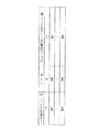
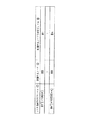
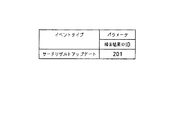
上記図14中のステップ43のイベントのパラメータは検索検索のIDだけであるので、図22から図26に変わった場合であれば、図29のようになる。
【0251】
図中には、左から右に“イベントタイプ”及び“パラメータ”の欄を有し、このパラメータの欄には“検索結果のID”が示されている。そして、イベントタイプ“サーチリザルトアップデート(SearchResultUpdate)”に対して検索結果のID“201”が表示されている。
【0252】
また、上記図11中のステップS16にて検索依頼元が送り、図16中のステップS61の前にサービスレジストリが受けるメッセージのパラメータも検索結果のIDだけであるので、一連の例の場合であれば図30のようになる。
【0253】
このメッセージを受けたサービスレジストリは図24の対応するエントリの不要通知をTRUEに変更し、IDが201である不要になったリストを破棄することになる。
【0254】
図28のデータベースを使用している場合には、この際にリストに含まれている外部のモジュールIDに対応するエントリをデータベースから削除することになる。
【0255】
以上説明したように各ノードに存在するサービスレジストリは協調作業を行いながら、他のサービスモジュールに対してはネットワークを意識する必要がないようにしている。
【0256】
次に、上述したような1対1通信及びブロードキャストによるメッセージのデータの具体的な形式について説明する。
【0257】
オブジェクトサービスモジュールからイベントマネージャ及びサービスレジストリに送出するメッセージは、図31に示すように、宛先、送信元を特定するヘッダと、メッセージの内容を特定するメッセージタイプのデータ、パラメータ長と示すデータ、メッセージに付随するパラメータを示すデータにより構成される。
【0258】
オブジェクトは、イベントを通知する場合、宛先のイベントマネージャは、メッセージタイプの部分にイベント通知を割り当て、イベント番号、イベントパラメータによりメッセンジャに依頼する。
【0259】
メッセンジャは、機器内のサービスモジュール間における送信先が1つの特定されているメッセージの送受信を管理する。すなわち各メッセンジャは、各サービスモジュールに設定されたIDと、ヘッダに設定された宛先のIDを基準にして、対応する宛先に各メッセージを通知する。この時メッセンジャは、対応するサービスモジュールが処理中の場合、このサービスモジュールに対する要求が失われないように、メッセージを保持する。
【0260】
なお、メッセンジャは、例えば各メッセージを一旦メモリに保持し、又は一連のメッセージの宛先を基準にしてアドレス間でリンクを形成し、このリンクのリストを管理することにより、各メッセージを対応するサービスモジュールに提供する。
【0261】
これによりこれらサービスモジュール間におけるメッセージの伝送において、メッセンジャは、いわゆる1対1通信により1の伝送元から送出したメッセージを1の伝送先に送信するようになされている。
【0262】
イベントマネージャは、メッセンジャを介して入力されるイベントメッセージを対応する機器内のサービスモジュールに配送し、またブロードキャストマネージャを利用する。
【0263】
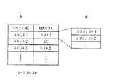
ここでサービスリストは、各イベントの通知を必要とするオブジェクトのリストであり、メッセンジャを介して通知される所定のメッセージにより更新される。サービスレジストリは、機器内サービスモジュールのリストであり、サービス検索の際にブロードキャストマネージャが利用する。
【0264】
このサービスリストは、図32に示すように、イベントの種類を示すイベント番号と、対応する宛先とを配列して形成される。
【0265】
イベントマネージャは、このサービスリストにしたがって、メッセンジャより取得したイベント情報のメッセージを配送する。すなわち、イベントマネージャは、“イベント1”について、“オブジェクト1”及び“オブジェクト2”を宛先にする旨、宛先リストが形成されている場合、通知されたメッセージを形成し、この2つのメッセージをメッセンジャに送信する。
【0266】
これに対して“イベント2”に対応する“メッセージ2”については、いずれのサービスモジュールにも配送することなくこのメッセージを処理する。さらにこのときイベントマネージャは、オブジェクトからブロードキャストの依頼があったと判断し、イベントマネージャは、サービスリストに基づいてこのメッセージを配送すると共に、ブロードキャストマネージャにこのメッセージのブロードキャストを依頼する。
【0267】
これによりテレビジョン受像器、ビデオテープレコーダでは、1対1通信又は1対多通信により得られる各種イベント情報を対応するサービスモジュールに発送するようになされている。かくするにつきテレビジョン受像器、ビデオテープレコーダでは、機器内においては、1対1通信によりメッセージが配送され、イベントマネージャは、単に複数の宛先に同一のメッセージを送信することになる。
【0268】
このようにしてメッセージを配送するにつき、イベントマネージャは、サービスリストに従って、宛先を特定してメッセージを操守する場合、メッセンジャに対してこのメッセージを送出する。メッセンジャは、宛先が機器内か否かを判断し、機器外の不特定多数が宛先のメッセージの場合、ブロードキャストマネージャにメッセージを送出する。
【0269】
イベントマネージャは、このようにブロードキャストマネージャ等にメッセージを送出する場合、図33中のAに示すようなメッセンジャにより通知されたメッセージの内容を転送する。これによりイベントマネージャは、ブロードキャストマネージャ等からは、同図中のBに示すように、オブジェクトよりメッセージの通知を受ける場合と同一の形式により、メッセージの通知を受け付ける。
【0270】
このようにしてメッセージを配送するにつき、イベントマネージャは、受信したメッセージのメッセージタイプを確認する。さらにイベントマネージャは、メッセージタイプによって、受信したメッセージがオブザーブのメッセージと判断すると、このメッセージの内容に従ってサービスリストを更新する。これによりビデオテープレコーダ等では、ネットワークに新たに機器が接続された場合等において、サービスリストを更新することにより、この増設された機器に対して種々のイベントを通信できるようになされている。
【0271】
図34は、このようなオブザーブの通知に使用されるメッセージのデータ形式を示す図である。なおこの図は、メッセージ部だけについて示す。このオブザーブのメッセージは、機器内外のオブジェクトにより必要に応じて生成され、例えばネットワークへの機器の接続が物理的に検出された場合に、この新たに増設された機器との間で、また既にネットワークに接続されている機器との間で、ネットワークメッセンジャを介して、又はブロードキャストマネージャを介してイベントマネージャに通知される。
【0272】
ここでこの一連のメッセージは、上記図31及び図33中のAに示したように、メッセンジャを介してサービスモジュール間で一般に送受されるメッセージに対してパラメータを拡大して形成される。すなわちサービスリストへのオブザーバの登録を求めるメッセージは、図34中のAに示すように、メッセージタイプにオブザーバのタイプを示す32ビットのデータが割り当てられ、通知を求めるイベント番号、通知先を示すオブザーバがパラメータに設定される。これに対して登録を取り消すメッセージは、同図中のBに示すように、メッセージタイプに取り消しを示すタイプのデータが割り当てられ、取り消しを求めるイベント番号、取り消す通知先を示すオブザーバがパラメータに設定される。
【0273】
またイベントマネージャは、サービスリストの更新に伴い、登録、取り消しを求めるサービスモジュールに対して、同様の形式により要求確認を示す応答のメッセージを配送する。またブロードキャストマネージャを介して通知されたメッセンジャや機器内でのイベント通知に対して、同様に応答確認を示す応答のメッセージを配送する。ここでイベント通知を受け取った場合には、サービスレジストリに従ってイベント発生を通知する。このときこの通知は、イベント発生通知であることが、同図中のCに示すように、続いて可変長によるパラメータ長のデータ、パラメータ長のデータ、パラメータのデータにより構成される。
【0274】
メッセンジャは、保持した外部機器IDのリストを検索し、この外部機器IDに従って伝送モジュールを介してネットワークにメッセージを送出する。このときメッセンジャはメッセージをネットワーク上での所定の形式に変換し、このメッセージを伝送モジュールに通知する。
【0275】
ここでこの所定の形式は、図35中のA及びBに示すように、ネットワークに接続された各ノードの機器で処理可能な、これらの機器に共通するパケットの形式であり、例えば同図に示すような形式である。すなわちメッセンジャは、メッセージをメッセージ部に設定し、このメッセージ部にヘッダを付加してパケットを形成する。
【0276】
ここでこのヘッダは、送信先でなる目的ノードが例えばIPアドレスであれば、ネットワークにより異なるが例えば32ビットのデータにより記述され、このパケットタイプによって特定対象に送出する送信のパケット、外部機器からの要求に応答して要求を発行した特定対象に発信する応答のパケット、ネットワークに接続された各機器に対する各機器のパケット等を識別できるようになされている。なおブロードキャストによる場合、この種の伝送モジュールに提供するパケットは、ネットワークメッセンジャに替えてブロードキャストマネージャが生成することになる。
【0277】
さらにヘッダは、送信のパケットと応答のパケットの対応を特定するためのメッセージIDが付加される。さらにヘッダは、目的ノードの内部における識別用のIDが32ビットのデータにより記述され、この目的IDによって目的ノードの機器において、機器内のいずれかのオブジェクトに対する応答かを特定できるようになされている。
【0278】
さらにメッセンジャは、伝送モジュールより入力されるパケットを取得し、自己の機器を目的ノードに設定したパケットを選択して、このパケットのメッセージを送出する。これによりメッセンジャは、機器内オブジェクトのメッセージを外部機器に出力し、またこれとは逆に外部機器より通知されたメッセージを機器内オブジェクトに通知する。
【0279】
またメッセンジャは、イベントマネージャ及びサービスレジストリと同様に、受信したメッセージによって保持した外部機器IDのリストを更新する。これによりビデオテープレコーダ等においては、増設された機器等に対しても、1対1通信により種々のメッセージを伝送できるようになる。
【0280】
ブロードキャストマネージャは、イベントマネージャ及びサービスレジストリよりメッセージを受け、伝送モジュールを介してこのメッセージをネットワークにブロードキャストする。さらにブロードキャストマネージャは、このブロードキャストをしたメッセージに関連する一連のメッセージを伝送モジュールを介してネットワークに送出する。
【0281】
またこれとは逆に、ブロードキャストマネージャは、他の機器よりネットワークにブロードキャストされたメッセージ、さらにはブロードキャストに関連するメッセージを伝送モジュールより取得し、イベントマネージャ及びサービスレジストリに通知する。
【0282】
次に、テレビジョン受像器、ビデオテープレコーダ等の電子機器に備えられ、これら電子機器の全体を制御するCPUの操作状態について説明する。
【0283】
ここで例示するCPUは、消費電力を変更する電力モードとしては、フルスピードモード(Fullspeed Mode)、スタンバイモード(Standby Mode)、サスペンドモード(Suspend Mode)、ハイバーネートモード(Hibernate Mode)の4種類を有するものである。
【0284】
フルスピードモードは、通常の動作モードであり、図36に示すように、全ての内部クロックが設定された周波数で動作する。図中において上から下へ、CPUに供給されるクロック信号であるマスタークロック(MasterClock)と、CPUの各部の信号であるマスターアウト(MasterOut)、Tクロック(TClock)及びPクロック(PClock)とのそれぞれの波形を示す。このフルスピードモードにおいては、上記のいずれの信号も動作している。
【0285】
ハイバーネートモードにおいては、図37に示すように、CPU内で生成される全てのクロックが全てハイレベルに固定されて停止する。図中では、CPUに供給されるクロック信号であるマスタークロックを除いたマスターアウト、Tクロック及びPクロックがハイレベルに固定されて停止している。
【0286】
なお、図中のリセット(Reset)及びコールドリセット(ColdReset)は、ハイバーネートモードからフルスピードモードへのモード移行のシーケンスを示すものである。
【0287】
また、図示しないが、スタンバイモードはタイマ/割り込みクロックを除く内部クロックが全てハイレベルに固定されて停止するモードであり、上記図36においてはPクロックがハイレベルに固定される。
【0288】
サスペンドモードは、タイマ/割り込みを除く内部クロックとTクロックが全てハイレベルに固定され、停止するモードであり、上記図36においてはTクロック及びTクロックがハイレベルに固定される。
【0289】
このように、このCPUにおいては、所定の内部クロックを停止させることにより消費電力を低減するモードを有している。すなわち、フルスピードモード、スタンバイモード、サスペンドモード及びハイバーネートモードの順に、停止される種類が増加するので、消費電力が削減される。
【0290】
したがって、テレビジョン受像器、ビデオテープレコーダ等の電子機器においては、CPUが通常に動作することが必要であるとき以外にはCPUをフルスピードモード以外の他の電力モードの移行させて待機状態あるいは停止状態とすることにより、消費電力の低減を図ることができる。
【0291】
次に、記録媒体について説明する。
記録媒体は、単数又は複数の制御対象の属性情報を取得する属性情報取得手順と、上記属性情報取得手順にて取得した属性情報を他の電子機器に送出して外部からの上記属性情報についての照会に対する応答を委託してから電源を停止状態にする属性情報管理手順とを有するプログラムが記録されたものである。
【0292】
また、記録媒体は、単数又は複数の制御対象の属性情報を取得すると共に他の電子機器から委託された場合には上記他の電子機器の制御対象の属性情報をも併せて取得する属性情報取得手順と、上記属性情報取得手順にて取得した属性情報について、上記他の電子機器から委託された場合には上記他の電子機器の制御対象の属性情報についても、外部からの照会に応答する属性情報管理手順とを有するプログラムが記録されたものである。
【0293】
この記録媒体は、上記プログラムが記録されたいわゆるCD−ROMやMOとして提供される。また、このプログラムは、通信回線等の媒体を介して供給される。
【0294】
以上述べたように、この発明に係る電子機器、電源制御方法及び記録媒体は、、例えばAVシステムを構成する各映像機器等に適用することができる。したがって、この発明は、ネットワークに対してメッセージをブロードキャストする情報ブロードキャスト手段と、装置内において、メッセージの配送を担当するイベントマネージャーとを配置することにより、機器内のオブジェクトから見て、機器内外を区別することなく、また特定対象、不特定対象を区別することなくメッセージの送受信をできるようにし、その分伝送に供する情報信号に対してネットワークを充分な時間開放することができるようにする。
【0295】
また、外部からの電源投入を意味するメッセージに対応するための方法としては、通常のメッセンジャを動かしておく方法もあるが、CPUがメッセージ毎に使用のソフトウェアを走らせなくてもよいように通信用のハードウェアで電源投入のメッセージのみを解釈して、CPUを含む本体部分の電源投入を行うことも考えられる。
【0296】
さらに、各ノードが、ノード内のサ−ビスモジュールのリストを管理し、不特定の機器に対するを利用した検索に答えるサービスレジストリを持ち、通常のサービスモジュールは オブジェクトはサービスレジストリを利用して必要なサービスモジュールを見つける構成のAVネットワークにおいて、使用中のサービスモジュールを持たない機器の電源を落しても他の機器のサービスモジュールが必要なサービスモジュールを見付けて利用できるように、電源を切る処理中にサービスレジストリが他の機器のサービスレジストリにリストの内容を知らせて検索に対する応答を委任し、委任されたサービスレジストリは検索に対して委任されたリスト中のサービスモジュールが必要になった際に同時に委任元のサービスレジストリを持つノードの電源を入れるようにするものである。
【0297】
【発明の効果】
上述のように、この発明に係る電子機器、電源制御方法及び記録媒体においては、他のノードのサービスモジュールに検索に対する応答を委任することによって、ブロードキャストメッセージ処理する必要もなくなり、CPUも止めることができるので電力消費を押さえることができる。
【0298】
また、この発明に係る電子機器、電源制御方法及び記録媒体においては、分散処理をしている場合には通常はサービスモジュールを持つ機器自体が検索に対応することになるので正当性が保証しやすい。さらに、電源を落すために委任している場合であっても、正当性のチェックは電源を落してから電源が入るまでの短時間のプロキシィを委任されているときにだけサービスモジュールを持つ機器のサービスレジストリに対する問い合わせにして検索を転送すればいいので、全体としては正当性のチェックを簡略にすることができる。
【図面の簡単な説明】
【図1】ネットワークに接続された電子機器の概略的な構成を示すブロック図である。
【図2】電源遮断直前の検索代行依頼に係る一連の工程を示すフローチャートである。
【図3】図2に続く工程を示すフローチャートである。
【図4】検索を行う属性情報に関するデータベースを示す図である。
【図5】検索代行依頼のためにサービスレジストリがブロードキャストするメッセージを示す図である。
【図6】代理検索を受けているサービスレジストリの検索依頼に係る一連の工程を示すフローチャートである。
【図7】ブロードキャストの検索要求に対する複数ノードの検索結果を示す図である。
【図8】他のサービスモジュールとの通信を行うためにサービスレジストリを使う変形例の一連の工程を示すフローチャートである。
【図9】ビデオテープレコーダの再生ボタンを押圧した際の一連の工程を示すフローチャートである。
【図10】図9に続く工程を示すフローチャートである。
【図11】他のサービスモジュールと通信を行うためにサービスレジストリを使う際の一連の工程を示すフローチャートである。
【図12】同一モード内のサービスモジュールから検索要求を受け付けた際の一連の工程を示すフローチャートである。
【図13】他ノードのサービスレジストリからの検索要求受信時の一連の工程を示すフローチャートである。
【図14】他ノードのサービスレジストリからの検索結果受信時の一連の工程を示すフローチャートである。
【図15】検索結果変更のイベント受けた際の検索結果依頼もとの一連の工程を示すフローチャートである。
【図16】検索依頼元のサービスレジストリからのリスト不要通知受信時の一連の工程を示すフローチャートである。
【図17】サービスレジストリの有するサービスモジュールのデータベースの第1の例を示す図である。
【図18】サービスレジストリの有するサービスモジュールのデータベースの第2の例を示す図である。
【図19】サービスレジストリの有するサービスモジュールのデータベースの第3の例を示す図である。
【図20】サービスモジュールからサービスレジストリへの検索依頼のメッセージの第1の例を示す図である。
【図21】サービスモジュールからサービスレジストリへの検索依頼のメッセージの第2の例を示す図である。
【図22】サービスモジュールが作成する検索結果のメッセージの一例を示す図である。
【図23】サービスレジストリがブロードキャストする検索依頼の転送のメッセージの一例を示す図である。
【図24】検索識別ID対してサービスレジストリが保持しているデータベースの一例を示す図である。
【図25】ブロードキャストの検索要求に対する検索結果のメッセージの一例を示す図である。
【図26】サービスレジストリが作成する検索結果のメッセージの一例を示す図である。
【図27】ノードIDを付加したモジュールIDの一例を示す図である。
【図28】内部でのモジュールIDと外部でのモジュールIDとノードIDに関するデータベースを示す図である。
【図29】検索結果不要通知のメッセージを示す図である。
【図30】検索を行う属性情報に関するデータベースを示す図である。
【図31】オブジェクトより送出されるメッセージを示す図である。
【図32】イベントマネージャのサービスリストを示す図である。
【図33】イベントマネージャよりブロードキャストマネージャに通知されるメッセージを示す図である。
【図34】サービスリストの登録等に関するメッセージを示す図である。
【図35】メッセンジャから伝送モジュールに送出するパケットの説明に供する図である。
【図36】フルスピードモードにおけるCPUの信号のタイミングチャートである。
【図37】ハイバーネートモードにおけるCPUの信号のタイミングチャートである。
【符号の説明】
2 テレビジョン受像器、3 ビデオテープレコーダ、2A,2B,3A,3B オブジェクト、2C,3C メッセンジャ、2D,3D イベントマネージャ、2E,3E サービスレジストリ、2I,3I 伝送モジュール、2J,3J パワーマネージャ[0001]
BACKGROUND OF THE INVENTION
The present invention relates to an electronic device that holds attribute information of a control target and responds to an inquiry about the attribute information, a power control method for controlling a power source of the control target, and a series of processing procedures to respond to an inquiry about the attribute information of the control target The present invention relates to a recording medium on which is recorded.
[0002]
[Prior art]
2. Description of the Related Art Conventionally, for example, a network in which an audio signal, a video signal, a control signal, and other information signals are transmitted by connecting AV equipment such as a television receiver, a video tape recorder, and a tuner is provided. As this network, there is a so-called distributed cooperative network in which AV devices connected to the network operate in a distributed manner and cooperate in accordance with information signals transmitted through the network.
[0003]
In a distributed cooperative network, an electronic device that functions as a node has a service registry that manages the attribute information of the service module of the object to be controlled, and can access the service module of other devices via the network. A network that performs distributed and coordinated operations is formed.
[0004]
[Problems to be solved by the invention]
By the way, when considering the possibility of a connection change when considering an AV network in the home, it is better to avoid that the service registry holds information about service modules of other nodes as much as possible. .
[0005]
The AV network mentioned here includes not only a television receiver and the like that would normally have little change in connection, but also a connection of a portable CD player or a video camera. It is highly possible and unnecessary to store such information on a device that is not known when disconnected in a specific server at the time of connection, for example.
[0006]
Therefore, according to the solution of always delegating to a proxy server that supervises other servers when connected, AV in the home where devices are frequently connected and disconnected from the network. Since it is conceivable that the proxy server is disconnected in the device network, processing at the time of disconnection must be performed.
[0007]
In the case of delegation at the time of connection, since there is a possibility that the connection has been changed by the time of the search, it is difficult to guarantee the data held by the proxy server, and it was necessary to check at the time of use.
[0008]
However, on the other hand, in a distributed and collaborative network where the service registries of each node collaborate, the service modules around the CPU and communication are always in operation to monitor and process the search request packets that flow through this network. Because it needs to be, it consumes power.
[0009]
In other words, in a system in which the service registry of each node in the basic network performs distributed cooperative operation, the service registry processes and answers even if all the service modules in the node are not used. There is a broadcast message that is distributed without specifying the destination.
[0010]
For this reason, the CPU must always be operating to process this broadcast message.IsTherefore, power is consumed even when the service module is not used.
[0011]
The present invention has been made in view of the above-described circumstances, and an electronic device that does not always have to operate in order for the CPU of the service registry of each node to respond to the broadcast message, and power control for controlling the power supply It is an object of the present invention to provide a method and a recording medium on which such a procedure is recorded.
[0012]
[Means for Solving the Problems]
In order to solve the above-described problems, an electronic apparatus according to the present invention controls one or a plurality of control objects, and includes attribute information holding means for holding the attribute information of the control objects, and the attribute information holding Managing the means, sending the attribute information held by the attribute information holding means to the attribute information management means provided in another electronic device, entrusting a response to the inquiry about the attribute information from the outside, and then stopping the power supply Attribute information management means, message transmission means for sending a message of an event occurring in the control object or objects to other service modules in the electronic device, and the event message via the network Broadcast means for broadcasting to other electronic devices.
[0013]
Moreover, the electronic device according to the present invention is an electronic device that controls one or a plurality of control objects, holds the attribute information of the control object, and the other electronic apparatus according to a consignment from another electronic apparatus Attribute information holding means that also holds the attribute information to be controlled, and attribute information held by the attribute information holding means by managing the attribute information holding means in accordance with the entrustment from the other electronic device As for the attribute information of the control target of the other electronic device, the attribute information management means that responds to the inquiry from the outside, and the message that transmits the message of the event that occurred in the control target to the other service module in the electronic device Transmission means, and broadcast means for broadcasting the message of the event to the other electronic device via a network. .
[0014]
In order to solve the above-described problem, a power supply control method according to the present invention includes an attribute information acquisition step of acquiring attribute information of the control target in the power control method of controlling a power supply of one or a plurality of control targets, Attribute information that manages the attribute information acquired in the attribute information acquisition process, sends the attribute information to other electronic devices, entrusts a response to an inquiry about the attribute information from the outside, and then turns the power off A management step, a message transmission step of transmitting a message of an event occurring in the control target to another service module in the electronic device, and a broadcast step of broadcasting the message of the event to the other electronic device via a network It has.
[0015]
The power control method according to the present invention is a power control method for controlling the power of one or a plurality of controlled objects, obtains the attribute information of the controlled objects, and performs the above-mentioned according to entrustment from another electronic device The attribute information acquisition step for acquiring the attribute information of the control target of the other electronic device and the attribute information acquired in the attribute information acquisition step according to the commission from the other electronic device. As for the attribute information of the control target of the device, the attribute information management step that responds to an inquiry from the outside, the message transmission step of transmitting the message of the event that occurred in the control target to other service modules in the electronic device, and the above A broadcast step of broadcasting an event message to the other electronic devices via the network.
[0016]
In order to solve the above-described problems, a recording medium according to the present invention includes an attribute information acquisition procedure for acquiring attribute information of one or more control targets, and attribute information acquired in the attribute information acquisition procedure as another electronic device. Attribute information management procedure for sending power to the device and entrusting a response to the inquiry about the attribute information from the outside and then shutting down the power supply, and the event message that occurred in the control target to other services in the electronic device A program having a message transmission procedure to be transmitted to a module and a broadcast procedure to broadcast the event message to the other electronic devices via a network is recorded.
[0017]
In addition, the recording medium according to the present invention acquires the attribute information of one or a plurality of control objects and also acquires the attribute information of the control object of the other electronic device according to the commission from the other electronic device. For attribute information acquisition procedure and attribute information acquired in the attribute information acquisition procedure, responding to inquiries from outside regarding the attribute information of the control target of the other electronic device according to the commission from the other electronic device Attribute information management procedure, a message transmission procedure for transmitting a message of an event occurring in the control target to another service module in the electronic device, and a broadcast of the event message to the other electronic device via a network A program having a broadcast procedure to be recorded is recorded.
[0018]
DETAILED DESCRIPTION OF THE INVENTION
Hereinafter, an electronic device, a power supply control method, and a recording medium according to the present invention will be described with reference to the drawings.
[0019]
FIG. 1 is a functional block diagram showing a communication system of an AV system in which a
[0020]
Here, the communication system of the
[0021]
The
[0022]
In the
[0023]
On the other hand, the
[0024]
In the
[0025]
When various events (events) that need to be notified to an unspecified number of people occur, these objects 2A to 3B notify the other service modules in the device via the
[0026]
Here, the event means a change in the state of each object 2A to 3B in the control target. For example, in the
[0027]
An event also occurs when each
[0028]
Each object 2A to 3B notifies each service module in the device of the occurrence of such an event by a message transmitted to and received from the service module in the device via the
[0029]
Further, the objects 2A to 3B acquire messages addressed to themselves sent from other objects in the device and messages addressed to themselves sent from the other devices to the
[0030]
In such a message exchange, these objects 2A-3B are
[0031]
Separately, by receiving the messages delivered by the
[0032]
For delivery of such messages, the
[0033]
As a result, the objects 2A to 3B can notify various messages inside and outside the device through one-to-one communication between the
[0034]
Furthermore, the
[0035]
The
[0036]
The
[0037]
The
[0038]
The
[0039]
Next, an example of power control in the
[0040]
The
[0041]
When the
[0042]
For example, when the
[0043]
The attribute information held in the
[0044]
The
[0045]
On the other hand, the
[0046]
As described above, the
[0047]
As a result, even when the power of the
[0048]
Next, another example of power control in the
[0049]
The
[0050]
When the
[0051]
That is, when the
[0052]
When the
[0053]
For example, the
[0054]
When the
[0055]
Further, when the
[0056]
As described above, when the
[0057]
The other electronic device may entrust the response to the inquiry to the attribute information to the
[0058]
Therefore, in the other electronic devices described above, power consumption is reduced while maintaining a distributed cooperative operation state that can respond to an inquiry from the outside. When the other electronic device falls under the search target, the power is controlled to be turned on when the search is performed.
[0059]
As described above, an electronic apparatus having a function as a node such as the
[0060]
In addition, electronic devices such as the
[0061]
Next, a series of steps related to the power supply control method will be described with reference to the flowcharts shown in FIGS.
[0062]
The steps shown in this flowchart show a processing procedure when a service registry of a television receiver entrusts a service registry of another electronic device to perform a search process on behalf of the television receiver.
[0063]
Here, it is assumed that the service module in the television receiver is not in operation and the software module at the user level is not in operation.
[0064]
This series of steps starts when the television receiver's service registry receives a power-off preparation message as an example of a power-down condition. That is, the series of steps is started when the service registry of the television receiver receives a message to prepare for power shutdown from the power manager. This power-off preparation message is an opportunity for the service registry to act on behalf of the search.
[0065]
In the first step S71, it is confirmed whether or not the service registry of the television receiver is currently performing a search agent for the electronic device of the other node.
[0066]
The data structure of a database for storing information about search agents for other electronic devices is, for example, as shown in FIG. In the figure, columns of “node ID”, “attribute information database ID”, and “number of attribute information bytes” are arranged in the horizontal direction from left to right. In the vertical direction in the figure, the node ID “BB”, the attribute information database “database B”, and the attribute information byte number “size B” are displayed in the first row. Subsequent lines are omitted. A database relating to attribute information for performing the search is held in, for example, a query database under the management of the service registry.
[0067]
By confirming the contents of this database, it is confirmed whether or not the service registry of the television receiver is acting for another electronic device. If the service registry of the television receiver is acting for the service registry of another electronic device, the process proceeds to step S72 as “YES”, otherwise the process proceeds to step S73 as “NO”.
[0068]
In step S72, if there is an entry in the database shown in FIG. 4, it is necessary to delegate the proxy to another electronic device from the head of the entry, that is, to re-request, so the node ID “BB” of the first entry. It is the target of proxy request for attribute information. That is, let this target node be BB. Then, the process proceeds to step S74.
[0069]
In step S73, since there is no entry in the database shown in FIG. 4, it is sufficient to request only the own attribute information of the television receiver. Therefore, the service registry of the television receiver uses the attribute information of the node ID of the own node as a proxy request target. Then, the process proceeds to step S74. For example, if the node ID of the own node is “AA”, the target node is set to AA. Then, the process proceeds to step S74.
[0070]
In step S74, a broadcast for transmitting a search proxy request message to an unspecified device is performed, including the size of the attribute information requesting the search proxy request and the node ID to which the attribute information belongs as parameters. Then, the process proceeds to step S75. This broadcast will be described later.
[0071]
Here, the size of the attribute information is notified in order to determine whether or not there is room for storing necessary attribute information in the RAM area or the like of the node when another node takes over the search proxy..
[0072]
The search proxy request message is as shown in FIG. That is, in the figure, three lines of “sender ID”, “proxy request identification ID”, and “proxy request content” are represented in order from left to right, and further, a column of “proxy request content” Consists of columns of “attribute information size” and “belonging node ID”. Then, the sender ID “XXXXXXX”, the proxy request identification ID “2345”, the attribute information size “size B”, and the belonging node ID “BB” are displayed.
[0073]
In step S75, the process waits for a reply from another node for a predetermined time. That is, a response from another node to the message broadcast in step S74 is accepted. Then, the process proceeds to next Step S76.
[0074]
Processing branches at step S76 depending on whether there is a response from another node at step S75. The service registries of other nodes do not respond if they cannot perform the search proxy, so if there is any response, the service registry is ready to take over the proxy. If there is a reply, the process proceeds to step S78 as “YES”, and if there is no reply, the process proceeds to step S77 as “NO”.
[0075]
As a parameter for responseGenusIncludes a flag indicating whether or notBe turnedThis can be considered as a modification.This is because some nodes make search agent requests to a plurality of nodes, and in this case, there is no need to send data.
[0076]
As a modified example, when there is a response that attribute information is unnecessary in step S76, there is no need to make a new search request. This is because a search request has already been received.
[0077]
In step S77, there is no reply within a predetermined time, and the request processing has failed because there is no partner requesting the search agent. In this case, the television receiver's service registry needs to respond to the search and tells the power manager that the CPU cannot be stopped. Then, the process proceeds to step S82. Note that “(2)” in FIG. 2 means that the procedure is connected to “(2)” in FIG.
[0078]
In step S78, a search request is made to the service registry that has responded in step S76. The attribute information sent at this time is all the attribute information currently possessed with respect to the node ID to which the node belongs and the service module of the node. Then, the process proceeds to step S79. Note that “(1)” in FIG. 2 means that the procedure is connected to “(1)” in FIG.
[0079]
In step S79, the process branches according to the condition that what is currently processed by the service registry of the television receiver is related to the node for which it is acting. If the current processing is related to the node acting on behalf of the user, the process proceeds to step S80 as “YES”, otherwise the process proceeds to step S81.
[0080]
In this step S79, here, the value of the target node (targetNode) which is a variable holding the target node is checked to confirm which node the processing target from step S74 to step S78 relates to. To do.
[0081]
In step S80, if the processing target is not the attribute information of the own node, the request has been made again to the node that has received the proxy request, and it is no longer necessary to perform the proxy. The corresponding node ID entry is deleted from the database relating to the attribute information to be searched. Thereafter, the process returns to step S71, and the process is repeated until all necessary requests are completed or cannot be requested. Here, when all the nodes acting on its own are finished, the process proceeds to a search proxy request process for the own node in step S73. Note that “(3)” in FIG. 3 means that the procedure is connected to “(3)” in FIG.
[0082]
On the other hand, in step S81, when the processing target is the attribute information of the own node, the request has been completed for all the attribute information. That is, the search proxy request is successful. Then, the process proceeds to next Step S82.
[0083]
In step S82, the service registry of the television receiver notifies the power manager of the success or failure of the process. When the process is successful, the power manager controls the power supply to the stop state. However, when the process fails, the CPU needs to be operating, so the power supply is kept on.
[0084]
In step S82, the series of processes is terminated, and the process proceeds to the next message.
[0085]
Next, a series of procedures when receiving a search request for a service registry undergoing proxy search will be described with reference to the flowchart shown in FIG. Here, a case where the service registry of the television receiver is sent the attribute information of the service module which is the object of the video tape recorder from the service registry of the video tape recorder, and the response for this attribute information is entrusted. .
[0086]
The service registry of the television receiver that has accepted the search agency in place of the service registry of the video tape recorder has an attribute information database other than its own database. Therefore, in addition to the case of searching only the nodes of the television receiver, the search processing procedure needs to be somewhat changed, and the search processing for the database needs to be repeated by the number of databases.
[0087]
Further, if the requested database includes a service registry of the television receiver, it is necessary to send a power-on message to the corresponding node.
[0088]
This series of steps starts when the service registry of the television receiver searches a database of attribute information of its own node.
[0089]
In the first step S91, the number of database entries related to search information for performing the search shown in FIG. 4 is checked. Here, in this database, N is the number of entries such as the node ID “BB” requesting the television receiver to perform a search proxy. Then, the process proceeds to next Step S92.
[0090]
In step S92, the number i of databases that have been searched out of the number N of databases that have been requested to be substituted is set to zero. That is, the initial setting is i = 0. Then, the process proceeds to next Step S93.
[0091]
In step S93, it is checked whether there is an attribute information database that has not been processed. That is, the branch is made according to the condition that i <N, where the number i of databases for which the search processing has been completed is smaller than the number N of databases requested to be searched. If this condition is met, there is an unprocessed database, so “YES” and the process proceeds to step S94. If this condition is not satisfied, all processing has been completed, so the search request source ID is notified to the search request source as “NO”, and this series of steps is completed.
[0092]
In step S94, a search is made in the attribute information database of the database next to the current i-th database among the database entries shown in FIG. 4, that is, the database of the (i + 1) -th entry. Then, the process proceeds to next Step S95.
[0093]
In step S95, the process branches depending on the condition that the corresponding service module exists in step S94. If this condition is satisfied, the process proceeds to step S96. If this condition is not satisfied, the process proceeds to step S98.
[0094]
In step S96, the corresponding service module in step S94 is added to the list. At this time, since the result of step S94 is the service module ID in another node, conversion is necessary. Then, the process proceeds to next Step S97.
[0095]
In step S97, since there is a possibility that the service module receives communication because it corresponds to the search, the service registry of the television receiver sends a power-on message to the corresponding node. Then, the process proceeds to next Step S98.
[0096]
If the power is turned on successfully, the node can receive the search by itself, and it is not necessary to request a search agent. Therefore, the service registry of the television receiver has the attribute for performing the search shown in FIG. The entry of the node is deleted from the information-related database, and the attribute information database is also deleted.
[0097]
It should be noted that at this stage, it is not known whether or not the corresponding node receives communication, and there is a possibility that the search agent will be re-requested immediately. Therefore, there is a modification in which the database requested to be searched is not deleted.
[0098]
In step S98, the number i of processed databases is incremented. That is, i = i + 1 is set. Then, the process returns to step S93.
[0099]
Here, as a modification, the service modules belonging to a plurality of nodes can be changed to the format shown in FIG. 7 so that they can be notified by one message.
[0100]
In the drawing, there are columns of “search identification ID”, “number of nodes”, “node ID”, and a plurality of “number of applicable modules” in order from left to right. In the first line, the search identification ID “1234”, the number of nodes “2”, the node ID “BB”, the number of corresponding modules “n”, the corresponding module ID “B1”,..., The corresponding module ID “Bn”. "Is displayed. In the next line, the node ID “CC”, the number of corresponding modules “m”, the corresponding module ID “C1”,..., The corresponding module ID “Cm” are displayed.
[0101]
By using this message format, the search result can be notified by one message to the service modules belonging to a plurality of nodes.
[0102]
Next, a modification of the power supply control method will be described with reference to the flowchart shown in FIG.
[0103]
In an implementation where the service registry creates a proxy for the destination of another node when it receives a search result from another node, when the list is no longer used, it is a candidate for the appropriate timing to delete the proxy It is conceivable that processing for notifying the service registry that the list is no longer necessary is not performed until the communication is completed.
[0104]
However, holding the list unnecessarily is a waste of memory, and when new search results are returned from other nodes, list update processing or list change event processing must be performed. Don't be.
[0105]
In order to avoid these wastes, notify the service registry of the person who is actually scheduled to communicate as a material for deciding whether to delete the proxy when notifying that the list is no longer needed. It is possible to implement an implementation that notifies that the list is no longer needed and notifies the end of communication after all communication is completed.
[0106]
In this case, instead of communicating with a destination included in the list, a communication partner can be selected from the destinations included in the list, and the communication partner can be communicated to the service registry.
[0107]
In this case, the process can be divided into a process that requires the entire list and a process that requires several destinations included in the list. In this implementation, proxies whose destinations are not known to communicate are deleted when the list is no longer needed, and proxies whose destinations are known to communicate are notified that communication has ended. Will be deleted. There is no limit to the number of destinations scheduled for communication.
[0108]
This series of processes starts when communication with other service modules in the network becomes necessary.
[0109]
In the first step S101, a search request message is sent to the service registry of the same node. In the next step S102, the search result from the service registry is waited. In the subsequent step S103, the search result of the service registry is waited for. The ID of the list containing is received. Then, the process proceeds to the next step S104.
[0110]
Processing branches at step S104 depending on the condition that the number of destinations included in the list is zero. That is, if the number of destinations included in the list is 0, “YES” is selected and the process proceeds to step S107. Otherwise, “NO” is determined and the process proceeds to step S105.
[0111]
In step S105, a communication partner is selected from the destinations included in the list. In the next step S106, the communication partner is notified to the service registry. Then, the process proceeds to step S107.
[0112]
In step S107, the service registry is notified that the list becomes unnecessary. In the next step S108, processing that requires communication with the communication partner is performed, and in the subsequent step S109, the service registry is notified that the communication has ended. Then, a series of steps related to processing that requires this communication is completed.
[0113]
Through the above procedure, work efficiency is improved by notifying the service registry of the party that actually communicates.
[0114]
Next, as a specific example of the power supply control method, a series of steps started by the occurrence of an event of pressing the playback button in the video tape recorder will be described with reference to the flowcharts shown in FIGS.
[0115]
In this specific example, as a simple example, it is assumed that each AV device in the house is connected to a digital network, and all data distribution and the like can be operated by software. A television receiver and a video tape recorder are connected to this network.
[0116]
This series of steps is an example in which communication between service modules of devices connected to the network is required, and is started when the user inserts a video tape into the video tape recorder and presses the playback button. . That is, this series of processes is started by the occurrence of an event of pressing the playback button of the video tape recorder.
[0117]
In the first step S111, a device whose service module type includes a display component is searched for in the network. And it progresses to step S112 following this.
[0118]
In step S112, the processEndedA variable I representing the number of databases is set to zero. Then, the process proceeds to next Step S113.
[0119]
In step S113, the process branches depending on the condition that there is an unprocessed search result. That is, assuming that the number of databases to be processed is N, if N> I is satisfied, search results that have not been processed remain, so that the process proceeds to step S114 as “YES”. If this condition is not satisfied, search is performed. Since the process is finished, "NO" is determined and the process proceeds to the step S122. Note that “(2)” in FIG. 9 means that the procedure is connected to “(2)” in FIG.
[0120]
In step S114, the first element that has not been processed is processed. Here, since the number of processed databases is I, processing is performed on the (I + 1) th database, which is the first unprocessed database. When the database processing is completed, I, which is a variable representing the number of databases that have been processed, is incremented to I = I + 1. Then, the process proceeds to step S115.
[0121]
Processing branches at step S115 depending on the condition that the display is in use. That is, if this condition is satisfied, “YES” is returned to step S113, and if this condition is not satisfied, “NO” is determined and the process proceeds to the next step S116.
[0122]
In step S116, a use request is issued to the display, and the process proceeds to step S117.
[0123]
Processing branches at step S117 depending on whether the use request for the display at step S116 has been accepted. That is, if the request is accepted, the process proceeds to step S118 as “YES”, and if the request is not accepted, the process returns to step S113 as “NO”.
[0124]
In step S118, the process branches depending on whether the device including the display includes a speaker. That is, if the device including the display includes a speaker, the process proceeds to step S120 as “YES”, and if the device does not include the speaker, the process proceeds to step S112 as “NO”. Here, “(1)” in FIG. 9 indicates that the procedure is connected to “(1)” in FIG.
[0125]
In step S120, a speaker use request is issued, and the process proceeds to the next step S121.
[0126]
Processing branches at step S121 depending on whether the request at step S120 is accepted. That is, when the use request of the speaker is accepted, “YES” is set and the series of processes is ended. If the use request of the speaker is not accepted, “NO” is determined and the process proceeds to step S122.
[0127]
In step S122, a device whose service module type includes a speaker component is searched for in the network. Then, the process proceeds to next Step S123.
[0128]
In step S123, a variable I representing the number of databases that have been searched is set to zero. And it progresses to step S124 following this.
[0129]
Processing branches at step 124 depending on whether there is a search result that has not been processed. Assuming that the number of databases to be processed is N, when there is an unprocessed search result, that is, when N> I is satisfied, the process proceeds to step S125 as “YES”, and when the search is terminated and N> I is not satisfied, “ This series of processing is terminated as “NO”.
[0130]
In step S125, the first element of the database is processed. That is, the process is performed on the (I + 1) th database next to the variable I indicating the number of processes completed. When this process ends, the variable is incremented to I = I + 1. And it progresses to step S126 following this.
[0131]
Processing branches at step S126 depending on the condition that the speaker is in use. When the speaker is in use, “YES” is returned to step S124, and when the speaker is not in use, “NO” is determined and the process proceeds to the next step S127.
[0132]
In step S127, a use request is issued to the speaker, and the process proceeds to step S128.
[0133]
Processing branches at step S128 depending on whether the use request issued from the speaker at step S127 has been accepted. That is, if the request is accepted, the process proceeds to step S129 as “YES”, and if the use request is not accepted, the process returns to step S124 as “NO”.
[0134]
In step S129, reproduction is started and the video signal is sent to the display and the audio signal is sent to the speaker. Then, this series of steps is completed.
[0135]
Here, if there is no unprocessed search result in S113 or S124, it may be considered that an error has occurred and the process is interrupted. In this case, the display destination of the error message may be displayed not only on a display device such as a liquid crystal panel and an error lamp provided in the video tape recorder, but also on a terminal for network control.
[0136]
When direct connection via an analog communication line is included, a software module for controlling the part can be created and the user can input connection information. For this purpose, it is necessary that a device including an input device and a display device is included in the network.
[0137]
As described above, the power supply control method includes an attribute information acquisition step of acquiring attribute information of a service module of one or a plurality of objects, and a service including the attribute information acquired in the attribute information acquisition step in another electronic device. An attribute information management step of stopping the power supply after entrusting a response to the inquiry about the attribute information from the outside by sending it to the registry.
[0138]
In addition, the power control method acquires the attribute information of the service module of one or more objects, and when commissioned by another electronic device, also includes the attribute information of the service module of the object of the other electronic device. For the attribute information acquisition step to be acquired and the attribute information acquired in the attribute information acquisition step, if the other electronic device is commissioned, the attribute information of the service module of the object of the other electronic device is also external And an attribute information management process for responding to an inquiry from
[0139]
Next, communication in the service registry and service module provided in the electronic device will be described.
Each service module provided in the electronic device is configured to realize a cooperative operation such as a processing request by sending a message.
[0140]
Here, as means for transmitting information between service modules, one-to-one communication using a message queue and communication using an event in which the sender is not aware of a specific listener are supplied within each node. Shall.
[0141]
The service module here includes not only a device for realizing a certain function but also a program stored in a memory and executed by a CPU.
[0142]
When the service module is a program, the overall execution means is not shown, but an explanation is given using an object-oriented model that describes the operation of each service module for realizing each function. When time sharing on the same CPU, parallel processing using a plurality of CPUs, distributed processing, or the like is performed, the processing of the service module is regarded as being executed in parallel.
[0143]
An electronic device of each node is generally provided with a plurality of service modules, and a plurality of nodes are connected via a network, which is a situation assumed by the present invention.
[0144]
First, a search procedure in a state where a power supply is turned on to a basic node will be described. A service module that wants to communicate with a service module having a specific function or attribute sends a search request message to the service registry in the same node.
[0145]
The service registry that has received the search request uses information on the service module that is managed to check whether or not the search is present in the same node as itself. At the same time, the service registry that receives the search from the node requests the broadcast manager to send the search request to the entire network.
[0146]
Upon receiving the search request broadcast message from the network, the broadcast manager of each node delivers the search request to the service registry in each node. Whether the service registry that receives the search request from outside the node uses the information managed in the same way as when the search is received from within the node, and whether or not the search registry exists in the same node as itself Check. When a search request from outside the node exists in the local node, the result is notified to the service registry of the search request source.
[0147]
The service registry that receives the search request from the node creates a list based on its own search results while waiting for the results from the other service registries over the network. When they return, they are added to the list one by one. The service registry that receives the search request from the node creates its own search result, and notifies the ID of the search request list after a specified time has elapsed. The specified time can be zero.
[0148]
The search requester confirms the contents of the list returned from the service registry, and makes a processing request by communicating with the mailbox of the service registry included therein. When the list known to the search requester is no longer needed, a message is sent to the service registry indicating that it is no longer used, and the service registry deletes the list and returns it from other nodes. Search results for the list will be discarded.
[0149]
If the search results from other nodes are returned to the service registry before deleting the list ID after informing the search requester, add the contents of the corresponding list and check that the list contents have been updated. By generating the event shown, if the search source checks the event, a response can be made.
[0150]
Next, processing for each service module will be described with reference to flowcharts.
[0151]
The basic flow shows the processing of the service module that uses the service registry first, then the processing of the service registry that received the search request from the service module, and finally receives the search request from the service registry of another node. Shows the service registry processing.
[0152]
After that, the response of the service registry when the search result transferred to the service registry of another node is returned, and the processing method and search of the service module when the search result is added while processing the result from the service registry After showing the processing when the result becomes unnecessary, the proxy request of the service registry of another node will be described.
[0153]
First, a series of steps when using a service registry to communicate with other service modules will be described with reference to the flowchart shown in FIG.
[0154]
This series of processes starts when communication with other service modules in the network is required. That is, it is started when it becomes necessary to use a service module having a specific function or a software module providing a specific function in the network.
[0155]
In the first step S11, a search request message is sent to the service registry of the same node. That is, a search request including the type, attribute information, position information, etc. of the other party with whom communication is desired is sent to the service registry in the same node. Then, the process proceeds to next Step S12.
[0156]
In step S12, the process waits until a search result is returned from the service registry. In an environment where parallel processing can be performed, a process unrelated to the search result may be performed while waiting for a search result. Then, the process proceeds to step S13.
[0157]
In step S13, a list ID such as a list number including the search result of the service registry is received. If an object-oriented model is used, the destination received when communicating with the object representing the list is the destination or request for communicating with the communication partner that matches the search request that is the search result. The number of communication partners that satisfy the condition is obtained by communication with the list. However, in terms of implementation, it may be possible to receive direct data such as an address on the memory of array data including the destination of the communication partner. Then, the process proceeds to the next step S14.
[0158]
In step S14, the number of destinations included in the list is confirmed. That is, the branching is made based on the condition that the number of destinations included in the list is zero. If the number of destinations is 0, it can be understood that there is no communication partner to be required. Therefore, the process proceeds to step S16 for notifying the service registry that the list is no longer necessary as “YES”, and there is no communication partner. Move on to processing. Otherwise, it is “NO” and the process proceeds to the next step S15.
[0159]
In step S15, since the number of destinations included in the list is other than 0, communication is performed with the destinations in the list. For example, if the video tape recorder is searching for a display destination display on a network of AV devices in the house, communication is performed until one unused one is selected from the search results. And if the TV is going to display a channel list, it will communicate to all available tuners. In any case, how to use the list is up to the search source, not the service registry. Then, the process proceeds to next Step S16.
[0160]
In step S16, the service registry is notified that the list is no longer needed. Information received from the service registry in step S15 is used as identification information for specifying an unnecessary list at this time. The service registry identifies a search request based on this information and performs necessary processing. Then, a series of steps related to processing that requires this communication is completed.
[0161]
This series of processing does not necessarily have to be performed after all communication with the communication partner is completed. For example, in the example in which the video tape recorder searches for a display in step S16, if the process of finding a display that is not in use is completed, the display list that is the search result is not necessary thereafter. Absent.
[0162]
Next, a series of steps related to the service registry that has received the search request sent in step S11 will be described with reference to the flowchart shown in FIG. This series of steps starts from accepting a search request from a service module in the same node.
[0163]
In the first step S21, a search request is sent to the service registry of another node using the broadcast manager. That is, the broadcast manager is requested to broadcast the accepted search request to the service registries of other nodes. This is a model for preventing a normal service module from being aware of the network, and can also be implemented as a service module having both functions of a broadcast manager and a service registry.
[0164]
In addition to the search request, the broadcast content includes an ID for identifying the broadcast source node, an ID indicating the search request addressed to the service registry, and a search request corresponding to the reply. A search identification ID for identification is included. Then, the process proceeds to next Step S22.
[0165]
In step S22, an ID such as a list for specifying a result is prepared as a search source. Corresponding to this ID, a data structure such as an array is created.
[0166]
Since it is necessary to add to this data structure when it returns from the node for the search request sent in step S21 later, the correspondence between the search identification ID sent in step S21 and the ID of the data structure prepared here is recorded. Keep it. Then, the process proceeds to step S23.
[0167]
Here, although the ID depends on the program language and OS at the time of mounting, the object ID, the address of the memory, the ID managed by the service registry, and the like are used.
[0168]
In step S23, an attribute database that is a database related to the service module of the own node is searched, and the ID of the service module that matches the search request is added to the data structure prepared in step S22. At this stage, the search result consists only of service modules existing in the same node. Then, the process proceeds to step S24.
[0169]
In step S24, the ID prepared in step S22 is notified to the search source. Since this ID is referenced only within the same node, it is sufficient that consistency is obtained only within the node regardless of the format. Then, the series of steps for processing the search request from the service module is finished, and the processing of the next message is started.
[0170]
Actually, as a series of search processing, further processing is performed when a response to the search broadcast in step S21 is returned, but this is handled as processing for another message.
[0171]
Next, a series of steps for a service registry that has received a search request from a service registry from another node broadcasted in step S21 will be described with reference to the flowchart shown in FIG.
[0172]
This series of steps is basically the same as the processing when receiving the search request from the service module of the own node described above, but the broadcast in step S21 is not performed and the search result is communicated between the nodes. The difference is that not only the ID of the list but also the contents are notified in order to convey it.
[0173]
This series of processes starts from accepting a search request from the service registry of another node. In the first step S31, a list or an array is prepared as a data structure for storing information to be returned to the search source..
[0174]
Step S31In, a list to be returned to the search request source is created. Subsequent step S32In step S3, the database is searched for the service module of its own node, and the ID of the service module that matches the search request is obtained.1Add to the data structure prepared in. The search result consists only of service modules existing in the same node. And step S33Proceed to
[0175]
Step S33In step S3, the original node2A list of service module IDs as a result of the search is notified. Unlike the above case, it does not indicate the entire data structure prepared in step S32, but notifies the individual elements and the number of elements included in the list. When notifying the result, the search identification ID for indicating which search request is associated with the search result is also notified at the same time.
[0176]
The reason for notifying all the contents here is to omit the confirmation of elements by performing inter-node communication later, so that the timing of discarding when the list becomes unnecessary can be determined within the node It is also to do. As a modification, it is also conceivable to notify only the ID of the data structure.
[0177]
However, only the data structure ID was notified in step S24.,When a search result from another node is returned as a result of the processing in the figure later and the contents are added,As an ID for notifying that there has been a change, this step S3.3Is the result of this node,Because there is no need to change later,There is no problem even if the contents are notified.
[0178]
In any case, since the ID of the service module notified here is processed by another node, the number of bits needs to be defined in the network. This is a significant difference from the above-described case where an arbitrary ID can be used at each node.
[0179]
In step S34, step S31Create in step S32The data structure with the added element in is no longer needed and is discarded. Note that when only the data structure ID is notified as a modification of step S34, this processing cannot be performed at this time, and is performed when a message for requesting list destruction is received. Additional processing is required to discard useless data when disconnected from the network.
[0180]
This step S34Then, the series of steps for the search request from the service registry of the other node is terminated, and the processing of the next message is started.
[0181]
Next, a series of steps in the service registry that has received the search result notified in step S33 will be described with reference to the flowchart shown in FIG.
[0182]
This series of steps starts by receiving a search result message from the service registry of another node. This message includes the search identification ID added at the time of broadcasting in step S21 and the list and number of service registry IDs that match the search contents.
[0183]
In the first step S41, using the record prepared in step S22 in FIG. 12, the data structure ID corresponding to the search identification ID is specified, and it is confirmed whether it is in use. In use here means that the list unnecessary notification in step S16 in FIG. 11 has not been received.
[0184]
If the list corresponding to the search identification ID is in use, the process from step S42 is performed as “YES”. However, if the list unnecessary notification has already been received, the search result of other nodes is also unnecessary, so “NO”. This series of steps is completed.
[0185]
In step S42, the service module ID list included in the received search result is added to the data structure confirmed in step S41. Then, the process proceeds to next Step S43.
[0186]
In step S43, the event manager is notified of an event indicating that the contents of the data structure have changed, thereby providing an opportunity for a service module interested in the data structure to perform processing. . The event parameter includes the ID of the data structure changed in step S42. This completes this series of steps and proceeds to processing the next message.
[0187]
Although the event manager is used in step S43, a modification in which the service registry itself records the data of the search source and notifies it by one-to-one communication is possible.
[0188]
If the number of elements in the search result is 0, no change has occurred, so it is not necessary to perform the notification in step S43. However, whether the number of elements has changed can be confirmed by the user, and if the number of elements is 0, there can be a modification in which the search result is not notified in the first place. In that case, confirmation is not essential. Therefore, it is not included in the above flowchart.
[0189]
Further, a variation may be considered in which a reply from another node is waited for a predetermined time between step S32 and step S33 in FIG. 13 and no additional processing is performed once the search result is notified to the search source. In this case, being in use in step S41 means that a reply is waiting, and step S43 is not necessary.
[0190]
The processing performed by the search request source when there is a change in the search result in step S43 is various and differs depending on the situation and cannot be shown as a flowchart. For example, if the purpose is to find a display that is not in use as mentioned above, no processing is necessary if it is already found, and if it is not found, the added one is checked. Become. If the purpose is to display a list of channels that can be provided by all tuners, communication is performed to obtain channel information of the added tuners.
[0191]
Next, a series of steps for a search request source when receiving a search result change event will be described with reference to a flowchart shown in FIG.
[0192]
This series of processes is started by receiving an event notification of a search result change. That is, the event notification is received as a result of the service registry using the event manager in step S43 in FIG. Or it is notified by a message directly from the service registry.
[0193]
In the case of an implementation using an event manager, in order to receive this notification, it is necessary to inform the event manager that he / she is interested in the search result change event by step S14 in FIG.
[0194]
In the first step S51, it is confirmed whether or not the ID of the changed data structure is in use. This is mainly because in the case of event notification, it is determined only by the type of event, and there is a possibility that notification is also given for unrelated items. Even if notified directly from the service registry, there is no loss in order to avoid mistakes, but it is not essential.
[0195]
If the ID of the data structure is in use, the process proceeds to step S52 as “YES”. If not, the series of processes is terminated as “NO” and the process proceeds to the next message.
[0196]
In step S52, as described above, necessary processing is performed according to the situation. Then, this series of steps is finished, and the processing of the next message is started.
[0197]
Next, a series of steps for the service registry that has received the list unnecessary notification in step S16 in FIG. 11 will be described with reference to the flowchart shown in FIG.
[0198]
This series of steps starts when the service registry receives the list unnecessary notification sent by the search requester in step S16. The list includes an ID for specifying the list as a message parameter.
[0199]
In the first step S61, information indicating that the list ID is not used is stored. This is used for the determination in step S41 in a situation where it is not known when the search results from the service registries of other nodes are returned. Here, as a method of storing information, for example, it is conceivable to set a non-use flag for the ID. Then, the process proceeds to next Step S62.
[0200]
In step S62, the list itself is discarded. As a modification, it is conceivable that a plurality of lists are pooled and reused without discarding the list. In this case, since the same object ID and memory address are reused, the list ID is managed by the service registry, and here, processing for emptying the contents of the list is performed. Then, the series of processes is terminated, and the process proceeds to the next message process.
[0201]
As a modified example, when there is no list corresponding to the ID, it can be considered that step S61 is omitted by determining that the list is not used, and only step S62 is performed.
[0202]
Next, the data format of a message such as a search request on the communication path and the data format handled by each service registry will be described. Although various modifications are possible, an example of basically necessary information is shown.
[0203]
As a simple example, each service module information is stored in an attribute name and an arbitrary character string as an attribute.In the case of holding attribute information in the format of FIG.When it is desired to give a plurality of attributes to one service module, it has a plurality of entries.
[0204]
In the first example of the service module database of this service registry, the horizontal direction in the figure has three columns of “module ID”, “attribute name”, and “attribute” in order from left to right, In the vertical direction in the figure, an attribute name “module type” and an attribute “broadcast manager” are assigned to the module ID “1”, and an attribute name “module type” and an attribute “event manager” are assigned to the module ID “2”. The attribute name “module type” and the attribute “network manager” are displayed for the module ID “4”, and the attribute name “module type” and the attribute “display” are displayed for the module ID “11”. ing.
[0205]
Here, the module ID is used for identification within the node, and is also used as a message destination.
[0206]
Assuming that it has several attributes in advance, for example, it always has a type and a name for display, and if it is possible to have an arbitrary number of additional attributes, the format is as shown in FIG.
[0207]
In the second example of the service module database of the service registry, from left to right, “module ID”, “module type”, “module name”, “number of attributes”, “number of
[0208]
In this case, it is conceivable to reduce the storage area as compared with storing character strings by assigning meanings to numbers in advance for attributes that are determined to have. In the figure, regarding the module type, for example, “100” indicates a display, so that the same information as in FIG. 11 is held with a small number of bytes.
[0209]
In this example, the display “D-001” has one additional attribute, which is “size”, but the other service modules do not have additional attributes. If “D-001” has an attribute “color” indicating “b / w” or “color”, the number of attributes is “2”.
[0210]
As described above, with respect to a certain type of service module, as shown in FIG. 19, there may be a modification in which the storage area is further reduced by defining numerically the attribute type in advance for general attributes.
[0211]
In the third example of the service module database that this service registry has, from left to right, “module ID”, “module type”, “module name”, “number of attributes”, “attribute type”, “attribute” In the vertical direction in the figure, the module type “1”, the module name “broadcast manager”, and the number of attributes “0” are shown in the vertical direction in the figure. , Module type “2”, module name “event manager” and attribute number “0” for module ID “2”, module type “3”, module name “network messenger” and module ID “4” The attribute number “0” is the module type “100” and the module name for the module ID “11”. D-001 ”, the number of attributes“ 3 ”, the attribute name type“ 101 ”and the attribute“ 21 ”, the attribute type“ 102 ”and the attribute“ color ”are in the next line, and the attribute type“ is in the next line. “0”, attribute name “sound”, and attribute “stereo” are displayed.
[0212]
In the figure, when the attribute type is “0”, it is an undefined type, and an example is shown in which the attribute name needs to be distinguished. In this example, the attribute type “101” means size, and “102” means color. The module type “100” means a display as in FIG. In the case of a modular having a plurality of additional attributes, variable-length attribute data follows the number of subsequent attributes.
[0213]
In this example, the attribute itself is all a character string, but by adding a flag indicating that the attribute type is numeric data other than a character string, a numeric value such as an integer, floating point, boolean, Variations that allow enumerations and the like are also conceivable.
[0214]
The data format of the search request message that becomes the entrance of the flowchart of FIG. 12 varies depending on the database of the service registry and how complicated the search can be specified. When only a simple search is performed, it is as shown in FIG.
[0215]
In the figure, there are two columns of “search attribute name” and “search attribute” from left to right in the horizontal direction, and search attribute name “module type” and inspection attribute “display” correspond to each of them. Each is displayed.
[0216]
In this case, the expression format of the character string may be different depending on the processing system inside the node. For example, there are a Pascal format indicating the number of bytes at the head and a C or C ++ format in which data indicating the end of a character string is added.
[0217]
In the first example of the service module database shown in FIG. 17, since it is known that the attribute name and the attribute are always character strings, such a search request is sufficient. As in the second example shown or the third example shown in FIG. 19, the data may contain data other than the character string. Therefore, the information needs to be included in the search request itself.
[0218]
Accordingly, FIG. 21 shows a data format of a search request message including information other than a character string. In the figure, there are three columns of “search attribute type”, “search attribute name”, and “search attribute” from left to right, and corresponding to these, “search attribute type“ 101 ”and search attribute “21” is shown, and the column corresponding to the search attribute name is blank.
[0219]
Here, the search attribute is the same as the attribute ID in the database shown in FIG. The search attribute name is specified only when the search attribute type is 0 in the example of FIG.
[0220]
In addition, as an example of a database, in the case of a modified example that allows a search attribute (not shown) other than a character string, it is necessary to add attribute type information to indicate whether the search attribute is a character string or a number There is. Although it is efficient to assign a numerical value indicating each data type in advance, there may be a modification in which a character string is used in consideration of expandability.
[0221]
As a modification of the search request, it is possible to perform a complex search including logical operations such as AND, OR, NOT, and specify a search range only within a specific node, only within a node belonging to a specified group, etc. However, the description is omitted here.
[0222]
In the series of steps shown in FIG. 12, if the service registry that received the search request from the service module in the step before S21 has the database as shown in FIG. 19, the search result created in step S22. For example, as shown in FIG.
[0223]
That is, the search result list has columns of “corresponding module number” and “corresponding
[0224]
In step S24, the search request source is notified only of a list ID such as “201” indicating the entire search result, not “11” which is a service module corresponding to the search.
[0225]
On the other hand, the message broadcast to the service registries of other nodes in step S22 is as shown in FIG.
[0226]
In the figure, there are columns of “sender ID”, “search identification”, and “search content” in order from left to right, and the “search content” column includes “search attribute ID”, It has columns of “search attribute name” and “search attribute”. A sender ID “XXXXXXX”, a search identification ID “1234”, a search attribute ID “101”, and a search attribute “21” are displayed.
[0227]
In this figure, the broadcast manager is requested to broadcast, and the broadcast manager adds a header when it flows through the network. As described above, this header includes a source node ID, a broadcast ID, and the like.
[0228]
Since the node ID and the module ID in the node are required when sending back the result in response to the broadcast, the sender ID which is the module ID of the service registry in the node is included in the figure.
[0229]
When a response to the message in the figure is returned, it is necessary to remember which list should be processed according to the search identification ID (referred to in step S41 in FIG. 14). The data for this is, for example, as shown in FIG.
[0230]
That is, in the figure, there are three columns of “search identification ID”, “search result list ID”, and “unnecessary notification” in order from left to right. The result list ID “201” and the unnecessary notification “0 (FALSE)” are respectively shown.
[0231]
The entry for the new search identification ID is prepared when the broadcast request is made in step S21, and the search result ID prepared in step S22 is stored.
[0232]
Since it suffices if the database has been updated before the processing of FIG. 14 starts, the timing of actually adding an entry may be anywhere in the flowchart shown in FIG.
[0233]
However, in the case of a modification in which a high priority is given to the processing of communication between service registries, step S22 is executed before requesting broadcast in step S21 in FIG. Termination is important in preventing malfunctions.
[0234]
The processing of the service registry that has received the message of FIG. 23 is the process shown in FIG. 13, and the search result created internally is the same as that of FIG. As a new data format that appears here, there is a format shown in FIG. 25 that flows through the communication line because the search result sent in step S33 in FIG. 13 includes the contents, not the ID indicating the entire list. .
[0235]
The message shown in the figure is not broadcast but sent to the service registry of the broadcast source node as one-to-one communication. For example, it is sent to the service registry of the module ID “XXXXXXX” of the broadcast source of the node ID “AA”.
[0236]
The module IDs from “B1” to “Bn” included in this result are the module IDs in the node “BB” to which the service module belongs, and the meanings for other nodes should not be understood. Although it is a number, it is guaranteed that the messenger of the node “BB” will deliver the main body of the message to the service module by specifying it as a destination inside the node in the header of the message addressed to the node “BB”. .
[0237]
The same applies to “XXXXXXX” designated as the module ID in the node as a response destination when the service registry broadcasts, and the other nodes do not need to know what “XXXXXXX” means.
[0238]
However, since all nodes connected to the network need to be handled in the same manner, only the bit length of this module ID needs to be specified to 64 bits, for example.
[0239]
When the size of the module ID in the network and the module ID used inside the node are different, the service registry creates a database that records the correspondence between the ID as the destination notified to the outside and the module ID inside. It is necessary to refer to the messenger when managing and delivering messages from other nodes, but it is also a database that shows a simple correspondence relationship and is omitted from this discussion because it is out of this discussion.
[0240]
The service registry of the node “AA” that received the original search request as a result of receiving the message of FIG. 14 shows the n module IDs in FIG. 22 as the search result in its own node in step S42 in FIG. To be changed as shown in FIG.
[0241]
In the figure, there are n + 2 columns of “corresponding module number”, “corresponding
[0242]
Here, in the figure, the reason that “B1 ′” is not “Bn” but “B1 ′” is “Bn ′” is because the usage of the module ID in each node is arbitrary, so the node “ This is because the node “AA” designates another service module if the ID in “BB” remains unchanged.
[0243]
The simplest conversion from “Bi” to “Bi ′” uses a node ID concatenated before a module ID used for communication in the network as a module ID inside the node. Is to distinguish between internal service modules and external service modules by using them as node IDs. In this case, the relationship is as shown in FIG.
[0244]
In the drawing, from left to right, there are three columns of “module ID at node AA”, “node ID”, and “module ID at the node to which the service module belongs” in order, and at node AA Node ID “0” and the module ID “11” at the node to which the service module belongs, and the node ID “BB” for the module ID “B1 ′” at the node AA. The module ID “B1” at the node to which the service module belongs and the module ID “Bn” at the node AA have the node ID “BB” and the module ID “Bn” at the node to which the service module belongs. Each is displayed. This figure shows that Bi ′ = BB * (scale) + Bi.
[0245]
However, in this case, the handling of the module ID when the internal natural module ID and the external service module are included is different, and an extra storage area must be used for the internal service module.
[0246]
As a modified example to solve this, for example, the internal service module uses only less than 10000, and the module ID higher than that indicates an external service module. As a third database following the database and the database related to the search identification ID, there is a method of managing information of the internal module ID, the external module ID, and the belonging node ID.
[0247]
The database in this case is almost the same as the corresponding relationship in the figure, except that an entry for the service module belonging to the own node is not necessary, and a module ID having a natural length for the node can be used. FIG. 28 shows an example of such a database.
[0248]
In the figure, from left to right, there are three columns of “module ID at node AA”, “node ID to which it belongs”, and “module ID at node to which it belongs”, and module ID “at node AA” “ Node ID “BB” belonging to “B1 ′ (= 1001)”, module ID “B1” at the node to which it belongs, and node ID belonging to module ID “Bn ′ (= 10000 + n)” at the node AA “BB” and the module ID “Bn” at the node to which it belongs are shown.
[0249]
When a messenger delivers a message, it first checks whether the destination module ID is greater than or equal to the approximate value (for example, 10000), and if it is less than that, it delivers it to the service module inside the node as it is. For example, after inquiring about the actual module ID and the node ID to which the service registry belongs, it is delivered in cooperation with the messenger of the destination node.
[0250]
Since the event parameter at step 43 in FIG. 14 is only the ID of the search search, FIG. 29 shows the case where the event is changed from FIG.
[0251]
In the figure, there are columns of “event type” and “parameter” from left to right, and “search result ID” is shown in this parameter column. The search result ID “201” is displayed for the event type “Search Result Update (SearchResultUpdate)”.
[0252]
Further, since the search request source is sent in step S16 in FIG. 11 and the message parameter received by the service registry before step S61 in FIG. 16 is only the search result ID, it may be a series of examples. FIG. 30 is obtained.
[0253]
Upon receiving this message, the service registry changes the unnecessary notification of the corresponding entry in FIG. 24 to TRUE, and discards the unnecessary list whose ID is 201.
[0254]
When the database shown in FIG. 28 is used, the entry corresponding to the external module ID included in the list is deleted from the database.
[0255]
As described above, the service registries that exist in each node perform cooperative work, while making it unnecessary for other service modules to be aware of the network.
[0256]
Next, a specific format of message data by one-to-one communication and broadcast as described above will be described.
[0257]
As shown in FIG. 31, the message sent from the object service module to the event manager and the service registry includes a header for specifying the destination and the transmission source, message type data for specifying the message contents, data indicating the parameter length, and message. Is composed of data indicating parameters associated with.
[0258]
When an object notifies an event, the destination event manager assigns the event notification to the message type portion, and requests the messenger by the event number and the event parameter.
[0259]
The messenger manages transmission / reception of a message in which one transmission destination is specified between service modules in the device. That is, each messenger notifies each message to the corresponding destination based on the ID set in each service module and the destination ID set in the header. At this time, if the corresponding service module is being processed, the messenger holds the message so that a request for the service module is not lost.
[0260]
The messenger, for example, temporarily holds each message in a memory, or forms a link between addresses based on a destination of a series of messages, and manages a list of the links, so that each message corresponds to a service module. To provide.
[0261]
As a result, in message transmission between these service modules, the messenger transmits a message sent from one transmission source to one transmission destination by so-called one-to-one communication.
[0262]
The event manager delivers an event message input via the messenger to the service module in the corresponding device, and uses the broadcast manager.
[0263]
Here, the service list is a list of objects that need to be notified of each event, and is updated by a predetermined message notified through the messenger. The service registry is a list of in-device service modules and is used by the broadcast manager when searching for services.
[0264]
As shown in FIG. 32, this service list is formed by arranging event numbers indicating event types and corresponding destinations.
[0265]
The event manager delivers the event information message acquired from the messenger according to the service list. In other words, the event manager forms a notified message when the destination list is formed with “
[0266]
In contrast, “
[0267]
Accordingly, in the television receiver and the video tape recorder, various event information obtained by one-to-one communication or one-to-many communication is sent to the corresponding service module. Thus, in the television receiver and the video tape recorder, messages are delivered by one-to-one communication within the device, and the event manager simply transmits the same message to a plurality of destinations.
[0268]
When delivering the message in this way, the event manager sends this message to the messenger when the destination is specified and the message is managed according to the service list. The messenger determines whether or not the destination is within the device, and if an unspecified number outside the device is a destination message, it sends a message to the broadcast manager.
[0269]
When the event manager sends a message to the broadcast manager or the like as described above, the event manager transfers the content of the message notified by the messenger as indicated by A in FIG. As a result, the event manager accepts the message notification from the broadcast manager or the like in the same format as when receiving the message notification from the object, as indicated by B in FIG.
[0270]
In delivering the message in this way, the event manager confirms the message type of the received message. Further, when the event manager determines that the received message is an observable message according to the message type, the event manager updates the service list according to the content of the message. Accordingly, in a video tape recorder or the like, when a new device is connected to the network, various events can be communicated to the added device by updating the service list.
[0271]
FIG. 34 is a diagram showing a data format of a message used for such an observation notification. This figure shows only the message part. This observer message is generated as necessary by objects inside and outside the device. For example, when a connection of the device to the network is physically detected, the message is newly transmitted to the newly added device, and is already in the network. Is notified to the event manager via a network messenger or via a broadcast manager.
[0272]
Here, as shown in A in FIGS. 31 and 33, this series of messages is formed by expanding parameters with respect to messages generally sent and received between service modules via a messenger. That is, as shown in A of FIG. 34, a message for requesting registration of an observer in the service list is assigned 32-bit data indicating the type of observer as the message type, an event number for requesting notification, and an observer indicating the notification destination. Is set as a parameter. On the other hand, as shown in B in the figure, the message for canceling registration is assigned data of the type indicating cancellation to the message type, the event number for requesting cancellation, and the observer indicating the notification destination to cancel are set as parameters. The
[0273]
Further, the event manager delivers a response message indicating a request confirmation in the same format to the service module that requests registration and cancellation as the service list is updated. Similarly, in response to a messenger notified via the broadcast manager or an event notification in the device, a response message indicating a response confirmation is delivered. When an event notification is received here, the occurrence of the event is notified according to the service registry. At this time, this notification is an event occurrence notification, and is composed of variable length parameter length data, parameter length data, and parameter data, as indicated by C in FIG.
[0274]
The messenger searches the list of held external device IDs and sends a message to the network via the transmission module according to the external device ID. At this time, the messenger converts the message into a predetermined format on the network and notifies this message to the transmission module.
[0275]
Here, this predetermined format is a packet format common to these devices that can be processed by the devices of each node connected to the network, as shown by A and B in FIG. The format is as shown. That is, the messenger sets a message in the message part and adds a header to the message part to form a packet.
[0276]
Here, this header is described by 32-bit data, for example, depending on the network if the destination node as the destination is an IP address, for example. In response to a request, a response packet transmitted to a specific object that issued the request, a packet of each device for each device connected to the network, and the like can be identified. In the case of broadcast, a packet provided to this type of transmission module is generated by a broadcast manager instead of a network messenger.
[0277]
Further, a message ID for specifying the correspondence between the transmission packet and the response packet is added to the header. Further, in the header, an ID for identification inside the target node is described by 32-bit data, and by the target ID, it is possible to specify whether it is a response to any object in the device in the device of the target node. .
[0278]
Further, the messenger acquires a packet input from the transmission module, selects a packet in which its own device is set as a target node, and sends out the message of this packet. Thereby, the messenger outputs the message of the in-device object to the external device, and conversely, notifies the in-device object of the message notified from the external device.
[0279]
Further, the messenger updates the list of external device IDs held by the received message, similarly to the event manager and the service registry. As a result, in a video tape recorder or the like, various messages can be transmitted to the added devices or the like through one-to-one communication.
[0280]
The broadcast manager receives a message from the event manager and the service registry, and broadcasts this message to the network via the transmission module. Further, the broadcast manager sends a series of messages related to the broadcasted message to the network via the transmission module.
[0281]
On the other hand, the broadcast manager obtains a message broadcast to the network from another device, and further a message related to the broadcast from the transmission module, and notifies the event manager and the service registry.
[0282]
Next, an operation state of a CPU that is provided in an electronic device such as a television receiver or a video tape recorder and controls the entire electronic device will be described.
[0283]
The CPU exemplified here has four types of power modes for changing power consumption: full speed mode, standby mode, suspend mode, and hibernate mode. Is.
[0284]
The full speed mode is a normal operation mode, and all internal clocks operate at a set frequency as shown in FIG. From top to bottom in the figure, a master clock (MasterClock) which is a clock signal supplied to the CPU, and a master out (MasterOut), a T clock (TClock) and a P clock (PClock) which are signals of each part of the CPU. Each waveform is shown. In the full speed mode, any of the above signals is operating.
[0285]
In the hibernate mode, as shown in FIG. 37, all clocks generated in the CPU are all fixed at a high level and stopped. In the figure, the master-out, T-clock and P-clock except the master clock which is a clock signal supplied to the CPU are fixed at high level and stopped.
[0286]
Note that a reset (ColdReset) and a cold reset (ColdReset) in the figure indicate a mode transition sequence from the hibernate mode to the full speed mode.
[0287]
Although not shown, the standby mode is a mode in which all internal clocks excluding the timer / interrupt clock are fixed at a high level and stopped. In FIG. 36, the P clock is fixed at a high level.
[0288]
The suspend mode is a mode in which the internal clock and the T clock except the timer / interrupt are all fixed at a high level and stopped. In FIG. 36, the T clock and the T clock are fixed at a high level.
[0289]
Thus, this CPU has a mode for reducing power consumption by stopping a predetermined internal clock. That is, the number of types to be stopped increases in the order of full speed mode, standby mode, suspend mode, and hibernate mode, so that power consumption is reduced.
[0290]
Therefore, in an electronic device such as a television receiver or a video tape recorder, the CPU is shifted to a power mode other than the full speed mode except when it is necessary for the CPU to operate normally. By setting the stop state, power consumption can be reduced.
[0291]
Next, the recording medium will be described.
The recording medium transmits an attribute information acquisition procedure for acquiring attribute information of one or a plurality of control targets, and the attribute information acquired in the attribute information acquisition procedure to another electronic device. A program having an attribute information management procedure for deactivating a power supply after entrusting a response to an inquiry is recorded.
[0292]
In addition, the recording medium acquires attribute information of one or a plurality of control objects and, when entrusted by another electronic device, acquires the attribute information of the control object of the other electronic device. For the attribute information acquired in the procedure and the attribute information acquisition procedure, the attribute that responds to the inquiry from the outside for the attribute information of the control target of the other electronic device when commissioned from the other electronic device. A program having an information management procedure is recorded.
[0293]
This recording medium is provided as a so-called CD-ROM or MO in which the program is recorded. This program is supplied via a medium such as a communication line.
[0294]
As described above, the electronic device, the power supply control method, and the recording medium according to the present invention can be applied to, for example, each video device that constitutes an AV system. Therefore, according to the present invention, by disposing information broadcast means for broadcasting a message to the network and an event manager in charge of message delivery in the device, the inside and outside of the device can be distinguished from the object in the device. In addition, a message can be transmitted and received without distinguishing between a specific object and an unspecified object, and the network can be opened for a sufficient amount of time for an information signal to be transmitted.
[0295]
In addition, as a method for dealing with a message meaning power-on from the outside, there is a method of running a normal messenger, but for communication so that the CPU does not have to run the software used for each message. It is also conceivable that the main part including the CPU is turned on by interpreting only the power-on message by the hardware.
[0296]
In addition, each node has a service registry that manages a list of service modules in the node and answers searches using unspecified devices. Normal service modules require objects using the service registry. In an AV network configured to find a service module, during a process of turning off the power so that the service module of another device can find and use the required service module even if the device without the service module in use is turned off. The service registry informs the service registries of other devices of the list and delegates responses to the search, and the delegated service registry delegates at the same time when a service module in the list delegated to the search is needed Of the node with the original service registry It is intended to turn on the power.
[0297]
【The invention's effect】
As described above, in the electronic device, the power supply control method, and the recording medium according to the present invention, by delegating a response to the search to the service module of another node, it is not necessary to process the broadcast message, and the CPU is also stopped. It can reduce power consumption.
[0298]
In addition, in the electronic device, the power supply control method, and the recording medium according to the present invention, in the case of performing distributed processing, the device itself having the service module normally supports the search, and therefore it is easy to guarantee the validity. . Furthermore, even when delegating to turn off the power, the validity check is performed only when the proxy with a short time from turning off the power to turning on the power is delegated. Since it is sufficient to forward the search as a query to the service registry, the overall validity check can be simplified.
[Brief description of the drawings]
FIG. 1 is a block diagram illustrating a schematic configuration of an electronic device connected to a network.
FIG. 2 is a flowchart showing a series of steps related to a search proxy request immediately before power-off.
FIG. 3 is a flowchart showing a process subsequent to FIG. 2;
FIG. 4 is a diagram showing a database related to attribute information for searching.
FIG. 5 is a diagram illustrating a message broadcast by a service registry for a search proxy request.
FIG. 6 is a flowchart showing a series of steps related to a search request for a service registry that has undergone a proxy search.
FIG. 7 is a diagram illustrating search results of a plurality of nodes in response to a broadcast search request.
FIG. 8 is a flowchart showing a series of steps of a modified example in which a service registry is used to communicate with other service modules.
FIG. 9 is a flowchart showing a series of steps when the playback button of the video tape recorder is pressed.
FIG. 10 is a flowchart illustrating a process following FIG. 9;
FIG. 11 is a flowchart showing a series of steps when a service registry is used to communicate with another service module.
FIG. 12 is a flowchart showing a series of steps when a search request is received from a service module in the same mode.
FIG. 13 is a flowchart showing a series of steps when receiving a search request from the service registry of another node.
FIG. 14 is a flowchart showing a series of steps when receiving a search result from the service registry of another node.
FIG. 15 is a flowchart showing a series of steps from a search result request source when a search result change event is received.
FIG. 16 is a flowchart showing a series of steps when receiving a list unnecessary notification from the service registry of the search request source.
FIG. 17 is a diagram illustrating a first example of a service module database included in a service registry;
FIG. 18 is a diagram illustrating a second example of a service module database included in a service registry.
FIG. 19 is a diagram illustrating a third example of a service module database included in a service registry;
FIG. 20 is a diagram illustrating a first example of a search request message from a service module to a service registry.
FIG. 21 is a diagram illustrating a second example of a search request message from the service module to the service registry.
FIG. 22 is a diagram illustrating an example of a search result message created by a service module;
FIG. 23 is a diagram showing an example of a search request transfer message broadcast by a service registry.
FIG. 24 is a diagram showing an example of a database held in a service registry for a search identification ID.
FIG. 25 is a diagram illustrating an example of a search result message for a broadcast search request;
FIG. 26 is a diagram illustrating an example of a search result message created by the service registry.
FIG. 27 is a diagram illustrating an example of a module ID to which a node ID is added.
FIG. 28 is a diagram showing a database related to an internal module ID, an external module ID, and a node ID.
FIG. 29 is a diagram showing a search result unnecessary notification message;
FIG. 30 is a diagram showing a database related to attribute information for searching.
FIG. 31 is a diagram illustrating a message transmitted from an object.
FIG. 32 is a diagram showing a service list of an event manager.
FIG. 33 is a diagram illustrating a message notified from an event manager to a broadcast manager.
FIG. 34 is a diagram showing a message related to service list registration and the like.
FIG. 35 is a diagram for explaining a packet sent from a messenger to a transmission module;
FIG. 36 is a timing chart of CPU signals in the full-speed mode.
FIG. 37 is a timing chart of CPU signals in a hibernate mode.
[Explanation of symbols]
2 TV receiver, 3 video tape recorder, 2A, 2B, 3A, 3B object, 2C, 3C messenger, 2D, 3D event manager, 2E, 3E service registry, 2I, 3I transmission module, 2J, 3J power manager
Claims (10)
上記制御対象の属性情報を保持する属性情報保持手段と、
上記属性情報保持手段を管理し、上記属性情報保持手段の保持する属性情報を他の電子機器の備える属性情報管理手段に送出して外部からの上記属性情報についての照会に対する応答を委託してから電源を停止状態にする属性情報管理手段と、
上記制御対象において発生したイベントのメッセージを上記電子機器内の他のサービスモジュールに送信するメッセージ送信手段と、
上記イベントのメッセージを、ネットワークを介して上記他の電子機器にブロードキャストするブロードキャスト手段と
を備えることを特徴とする電子機器。In an electronic device that controls one or more controlled objects,
Attribute information holding means for holding the control target attribute information;
After managing the attribute information holding means, sending the attribute information held by the attribute information holding means to the attribute information management means provided in another electronic device, and entrusting a response to an inquiry about the attribute information from the outside Attribute information management means for turning off the power ;
Message transmitting means for transmitting a message of an event occurring in the control target to another service module in the electronic device;
An electronic apparatus, comprising a broadcasting means for broadcasting the event message to the other electronic device via a network.
上記制御対象の属性情報を保持し、他の電子機器からの委託に応じて上記他の電子機器の制御対象の属性情報をも併せて保持する属性情報保持手段と、
上記属性情報保持手段を管理して上記属性情報保持手段の保持する属性情報について、上記他の電子機器から委託された上記他の電子機器の制御対象の属性情報についても、外部からの照会に応答する属性情報管理手段と、
上記制御対象において発生したイベントのメッセージを上記電子機器内の他のサービスモジュールに送信するメッセージ送信手段と、
上記イベントのメッセージを、ネットワークを介して上記他の電子機器にブロードキャストするブロードキャスト手段と
を備えることを特徴とする電子機器。In an electronic device that controls one or more controlled objects,
Attribute information holding means for holding the attribute information of the control target, and holding the attribute information of the control target of the other electronic device in accordance with entrustment from the other electronic device;
Responds to external inquiries regarding the attribute information held by the attribute information holding means by managing the attribute information holding means, and the attribute information of the control target of the other electronic equipment entrusted by the other electronic equipment Attribute information management means ,
Message transmitting means for transmitting a message of an event occurring in the control target to another service module in the electronic device;
An electronic apparatus, comprising a broadcasting means for broadcasting the event message to the other electronic device via a network.
上記制御対象の属性情報を取得する属性情報取得工程と、
上記属性情報取得工程にて取得した属性情報を管理し、上記属性情報を他の電子機器に送出して外部からの上記属性情報についての照会に対する応答を委託してから電源を停止状態にする属性情報管理工程と、
上記制御対象において発生したイベントのメッセージを電子機器内の他のサービスモジュールに送信するメッセージ送信工程と、
上記イベントのメッセージを、ネットワークを介して上記他の電子機器にブロードキャストするブロードキャスト工程と
を有することを特徴とする電源制御方法。In a power supply control method for controlling the power supply of one or more control targets,
An attribute information acquisition step of acquiring the control target attribute information;
An attribute that manages the attribute information acquired in the attribute information acquisition step, sends the attribute information to another electronic device, entrusts a response to an inquiry about the attribute information from the outside, and then turns the power off Information management process ;
A message transmission step of transmitting a message of an event occurring in the control target to another service module in the electronic device;
A power supply control method comprising: a broadcast step of broadcasting the event message to the other electronic device via a network .
上記制御対象の属性情報を取得し、他の電子機器からの委託に応じて上記他の電子機器の制御対象の属性情報をも併せて取得する属性情報取得工程と、
上記属性情報取得工程にて取得した属性情報について、上記他の電子機器から委託された上記他の電子機器の制御対象の属性情報についても、外部からの照会に応答する属性情報管理工程と、
上記制御対象において発生したイベントのメッセージを電子機器内の他のサービスモジュールに送信するメッセージ送信工程と、
上記イベントのメッセージを、ネットワークを介して上記他の電子機器にブロードキャ ストするブロードキャスト工程と
を有することを特徴とする電源制御方法。In a power supply control method for controlling the power supply of one or more control targets,
Attribute information acquisition step of acquiring the attribute information of the control target, and also acquiring the attribute information of the control target of the other electronic device according to the commission from the other electronic device,
For the attribute information acquired in the attribute information acquisition step, for the attribute information of the control target of the other electronic device entrusted by the other electronic device, an attribute information management step that responds to an inquiry from the outside ,
A message transmission step of transmitting a message of an event occurring in the control target to another service module in the electronic device;
Power control method characterized by having a broadcast step of the event message via the network to broadcast to the other electronic devices.
上記属性情報取得手順にて取得した属性情報を他の電子機器に送出して外部からの上記属性情報についての照会に対する応答を委託してから電源を停止状態にする属性情報管理手順と、
上記制御対象において発生したイベントのメッセージを電子機器内の他のサービスモジュールに送信するメッセージ送信手順と、
上記イベントのメッセージを、ネットワークを介して上記他の電子機器にブロードキャストするブロードキャスト手順と
を有するプログラムが記録された記録媒体。An attribute information acquisition procedure for acquiring attribute information of one or more controlled objects;
Attribute information management procedure for sending the attribute information acquired in the attribute information acquisition procedure to another electronic device and entrusting a response to an inquiry about the attribute information from the outside, and then turning off the power supply ,
A message transmission procedure for transmitting a message of an event occurring in the control target to another service module in the electronic device;
A recording medium on which a program having a broadcast procedure for broadcasting the event message to the other electronic devices via a network is recorded.
上記属性情報取得手順にて取得した属性情報について、上記他の電子機器からの委託された上記他の電子機器の制御対象の属性情報についても、外部からの照会に応答する属性情報管理手順と、
上記制御対象において発生したイベントのメッセージを電子機器内の他のサービスモジュールに送信するメッセージ送信手順と、
上記イベントのメッセージを、ネットワークを介して上記他の電子機器にブロードキャストするブロードキャスト手順と
を有するプログラムが記録された記録媒体。Attribute information acquisition procedure for acquiring the attribute information of the control target of the other electronic device according to the entrustment from the other electronic device as well as acquiring the attribute information of the single or plural control targets;
For the attribute information acquired in the attribute information acquisition procedure, the attribute information management procedure for responding to an inquiry from the outside for the attribute information of the control target of the other electronic device entrusted from the other electronic device ,
A message transmission procedure for transmitting a message of an event occurring in the control target to another service module in the electronic device;
A recording medium on which a program having a broadcast procedure for broadcasting the event message to the other electronic devices via a network is recorded.
Priority Applications (2)
| Application Number | Priority Date | Filing Date | Title |
|---|---|---|---|
| JP26747597A JP3733709B2 (en) | 1997-09-30 | 1997-09-30 | Electronic device, power supply control method, and recording medium |
| US09/162,331 US6353765B1 (en) | 1997-09-30 | 1998-09-28 | Electronic apparatus power supply control method and recording medium |
Applications Claiming Priority (1)
| Application Number | Priority Date | Filing Date | Title |
|---|---|---|---|
| JP26747597A JP3733709B2 (en) | 1997-09-30 | 1997-09-30 | Electronic device, power supply control method, and recording medium |
Publications (2)
| Publication Number | Publication Date |
|---|---|
| JPH11112595A JPH11112595A (en) | 1999-04-23 |
| JP3733709B2 true JP3733709B2 (en) | 2006-01-11 |
Family
ID=17445366
Family Applications (1)
| Application Number | Title | Priority Date | Filing Date |
|---|---|---|---|
| JP26747597A Expired - Lifetime JP3733709B2 (en) | 1997-09-30 | 1997-09-30 | Electronic device, power supply control method, and recording medium |
Country Status (2)
| Country | Link |
|---|---|
| US (1) | US6353765B1 (en) |
| JP (1) | JP3733709B2 (en) |
Families Citing this family (9)
| Publication number | Priority date | Publication date | Assignee | Title |
|---|---|---|---|---|
| FR2778046B1 (en) * | 1998-04-23 | 2000-05-19 | Thomson Multimedia Sa | METHOD FOR MANAGING OBJECTS IN A COMMUNICATION NETWORK AND DEVICE FOR IMPLEMENTING IT |
| AU2002235472A1 (en) * | 2001-01-26 | 2002-08-06 | Netbotz, Inc. | Method and system for a set of network appliances which can be connected to provide enhanced collaboration, scalability, and reliability |
| WO2003077475A1 (en) * | 2002-03-12 | 2003-09-18 | Philips Intellectual Property & Standards Gmbh | Server for standby management in a network |
| EP1545051A1 (en) * | 2003-12-15 | 2005-06-22 | Alcatel | Method for waking up a sleeping device, a related network element and a related waking device |
| US20060207268A1 (en) * | 2005-03-17 | 2006-09-21 | International Business Machines Corporation | System and method for increasing the efficiency of a thermal management profile |
| CN101159825B (en) * | 2006-09-27 | 2012-03-21 | 松下电器产业株式会社 | Video receiving device, video data receiving system and authentication control method thereof |
| JP4561872B2 (en) * | 2008-05-15 | 2010-10-13 | ソニー株式会社 | Recording / reproducing apparatus and information processing method |
| US20100217451A1 (en) * | 2009-02-24 | 2010-08-26 | Tetsuya Kouda | Energy usage control system and method |
| US9825767B2 (en) | 2012-05-01 | 2017-11-21 | Avago Technologies General Ip (Singapore) Pte. Ltd | Service based power management in a network |
Family Cites Families (11)
| Publication number | Priority date | Publication date | Assignee | Title |
|---|---|---|---|---|
| JPH0495291A (en) * | 1990-08-10 | 1992-03-27 | Sony Corp | Electronic apparatus device |
| DE69203525T3 (en) * | 1991-04-26 | 2002-08-08 | Pioneer Electronic Corp., Tokio/Tokyo | Data transmission system in a vehicle. |
| US5410713A (en) * | 1992-01-02 | 1995-04-25 | Smith Corona/Acer | Power-management system for a computer |
| KR940016216A (en) * | 1992-12-28 | 1994-07-22 | 오오가 노리오 | Audio / Video System and Connection Settings |
| JPH06205313A (en) * | 1992-12-28 | 1994-07-22 | Sony Corp | Av system |
| FR2719396B1 (en) * | 1994-04-28 | 1996-06-28 | Sgs Thomson Microelectronics | Controller / control processor for communication protocol management. |
| JP3474665B2 (en) * | 1995-03-02 | 2003-12-08 | 富士通株式会社 | Power supply control apparatus and method for computer system |
| US6038625A (en) * | 1998-01-06 | 2000-03-14 | Sony Corporation Of Japan | Method and system for providing a device identification mechanism within a consumer audio/video network |
| US6052750A (en) * | 1998-01-06 | 2000-04-18 | Sony Corporation Of Japan | Home audio/video network for generating default control parameters for devices coupled to the network, and replacing updated control parameters therewith |
| US6170013B1 (en) * | 1998-03-27 | 2001-01-02 | Nortel Networks Limited | Method and apparatus for controlling access to network information sources |
| US6233611B1 (en) * | 1998-05-08 | 2001-05-15 | Sony Corporation | Media manager for controlling autonomous media devices within a network environment and managing the flow and format of data between the devices |
-
1997
- 1997-09-30 JP JP26747597A patent/JP3733709B2/en not_active Expired - Lifetime
-
1998
- 1998-09-28 US US09/162,331 patent/US6353765B1/en not_active Expired - Lifetime
Also Published As
| Publication number | Publication date |
|---|---|
| US6353765B1 (en) | 2002-03-05 |
| JPH11112595A (en) | 1999-04-23 |
Similar Documents
| Publication | Publication Date | Title |
|---|---|---|
| US6665727B2 (en) | Dynamic assignment of multicast network addresses | |
| US6366964B1 (en) | Method of and apparatus for dynamically enumerating objects representing devices within an IEEE 1394 serial bus networking | |
| US7991897B2 (en) | Communication management system for performance data | |
| JP5425070B2 (en) | Network repository for metadata | |
| US6446142B1 (en) | Method of and apparatus for dynamically binding subobjects into objects to represent functions and characteristics of a device within an IEEE 1394 serial bus network | |
| US8010665B2 (en) | Method of and apparatus for communicating data structures between devices in a networking environment | |
| US10831612B2 (en) | Primary node-standby node data transmission method, control node, and database system | |
| US20070286209A1 (en) | System and method for handling address resolution protocol requests | |
| US20040059722A1 (en) | Method and apparatus for discovery of dynamic network services | |
| CN101192942A (en) | Method for controlling retention of publications and publication/orderation agent | |
| US20060218239A1 (en) | Electronic musical apparatus | |
| JP3733709B2 (en) | Electronic device, power supply control method, and recording medium | |
| CN102333029A (en) | Routing method in server cluster system | |
| CN101147380A (en) | Method and apparatus for efficiently expanding a P2P network | |
| JP2003330827A (en) | Contents reproducing device, server connecting method, server connecting program and record medium | |
| JP2002344475A (en) | System and method for providing service to apparatus in home network and system and method being provided with service through home network | |
| US6647448B1 (en) | Method and apparatus for managing resource schedules in a peer to peer distributed networking environment | |
| JP2001513589A (en) | Queue system and method for point-to-point message transfer | |
| JP2009296128A (en) | Information processor, control method for information processor, and computer program | |
| JP3797344B2 (en) | Server client system | |
| JP2005311479A (en) | Network system, program recording reservation method, and information processing apparatus | |
| JP2001223730A (en) | Gateway device and recording medium | |
| JP2007272467A (en) | Distribution system, control device, control device program, management device, management device program, auxiliary device, auxiliary device program, and distribution system control method | |
| JPH04157940A (en) | Grouping method of nodes in network | |
| JPH11163924A (en) | Electronic mail system and recording medium for recording address managing program of the same |
Legal Events
| Date | Code | Title | Description |
|---|---|---|---|
| A521 | Request for written amendment filed |
Free format text: JAPANESE INTERMEDIATE CODE: A523 Effective date: 20040406 |
|
| A621 | Written request for application examination |
Free format text: JAPANESE INTERMEDIATE CODE: A621 Effective date: 20040406 |
|
| A977 | Report on retrieval |
Free format text: JAPANESE INTERMEDIATE CODE: A971007 Effective date: 20050610 |
|
| A131 | Notification of reasons for refusal |
Free format text: JAPANESE INTERMEDIATE CODE: A131 Effective date: 20050705 |
|
| A521 | Request for written amendment filed |
Free format text: JAPANESE INTERMEDIATE CODE: A523 Effective date: 20050830 |
|
| TRDD | Decision of grant or rejection written | ||
| A01 | Written decision to grant a patent or to grant a registration (utility model) |
Free format text: JAPANESE INTERMEDIATE CODE: A01 Effective date: 20050927 |
|
| A61 | First payment of annual fees (during grant procedure) |
Free format text: JAPANESE INTERMEDIATE CODE: A61 Effective date: 20051010 |
|
| FPAY | Renewal fee payment (event date is renewal date of database) |
Free format text: PAYMENT UNTIL: 20091028 Year of fee payment: 4 |
|
| FPAY | Renewal fee payment (event date is renewal date of database) |
Free format text: PAYMENT UNTIL: 20091028 Year of fee payment: 4 |
|
| FPAY | Renewal fee payment (event date is renewal date of database) |
Free format text: PAYMENT UNTIL: 20101028 Year of fee payment: 5 |
|
| FPAY | Renewal fee payment (event date is renewal date of database) |
Free format text: PAYMENT UNTIL: 20101028 Year of fee payment: 5 |
|
| S111 | Request for change of ownership or part of ownership |
Free format text: JAPANESE INTERMEDIATE CODE: R313113 |
|
| S531 | Written request for registration of change of domicile |
Free format text: JAPANESE INTERMEDIATE CODE: R313531 |
|
| FPAY | Renewal fee payment (event date is renewal date of database) |
Free format text: PAYMENT UNTIL: 20101028 Year of fee payment: 5 |
|
| R350 | Written notification of registration of transfer |
Free format text: JAPANESE INTERMEDIATE CODE: R350 |
|
| FPAY | Renewal fee payment (event date is renewal date of database) |
Free format text: PAYMENT UNTIL: 20101028 Year of fee payment: 5 |
|
| FPAY | Renewal fee payment (event date is renewal date of database) |
Free format text: PAYMENT UNTIL: 20111028 Year of fee payment: 6 |
|
| FPAY | Renewal fee payment (event date is renewal date of database) |
Free format text: PAYMENT UNTIL: 20111028 Year of fee payment: 6 |
|
| FPAY | Renewal fee payment (event date is renewal date of database) |
Free format text: PAYMENT UNTIL: 20121028 Year of fee payment: 7 |
|
| FPAY | Renewal fee payment (event date is renewal date of database) |
Free format text: PAYMENT UNTIL: 20121028 Year of fee payment: 7 |
|
| FPAY | Renewal fee payment (event date is renewal date of database) |
Free format text: PAYMENT UNTIL: 20131028 Year of fee payment: 8 |
|
| R250 | Receipt of annual fees |
Free format text: JAPANESE INTERMEDIATE CODE: R250 |
|
| R250 | Receipt of annual fees |
Free format text: JAPANESE INTERMEDIATE CODE: R250 |
|
| R250 | Receipt of annual fees |
Free format text: JAPANESE INTERMEDIATE CODE: R250 |
|
| R250 | Receipt of annual fees |
Free format text: JAPANESE INTERMEDIATE CODE: R250 |
|
| EXPY | Cancellation because of completion of term |