JP3733552B2 - Bedding - Google Patents
Bedding Download PDFInfo
- Publication number
- JP3733552B2 JP3733552B2 JP2002338504A JP2002338504A JP3733552B2 JP 3733552 B2 JP3733552 B2 JP 3733552B2 JP 2002338504 A JP2002338504 A JP 2002338504A JP 2002338504 A JP2002338504 A JP 2002338504A JP 3733552 B2 JP3733552 B2 JP 3733552B2
- Authority
- JP
- Japan
- Prior art keywords
- locking means
- attached
- buffer
- main body
- cover
- Prior art date
- Legal status (The legal status is an assumption and is not a legal conclusion. Google has not performed a legal analysis and makes no representation as to the accuracy of the status listed.)
- Expired - Fee Related
Links
Images


Landscapes
- Mattresses And Other Support Structures For Chairs And Beds (AREA)
- Invalid Beds And Related Equipment (AREA)
Description
【0001】
【発明の属する技術分野】
本発明は布団,マットレス,枕,クッション等の寝具類に関する。
【0002】
【従来の技術】
ベッドや椅子の上で頻繁に姿勢を変えることができないときに、身体の特定の部位が長時間にわたって圧迫されると、褥瘡(いわゆる床擦れ)が発生することがある。
この褥瘡を防止するための寝具類の一種として、環状の緩衝体からなるドーナツ状のクッションが知られている。
このクッションは、上記緩衝体によって身体の特定の部位、特に患部に加わる体圧を緩衝して褥瘡の発生や悪化を防止することができるものと認められる(たとえば、特許文献1参照。)。
【0003】
【特許文献1】
登録実用新案第3031011号公報(第1,3図)
【0004】
【発明が解決しようとする課題】
しかし、特に患部は、緩衝体に所要の緩衝作用があるとしても、その緩衝体に当接すること自体で痛みを感じるようなことがあるが、上記ドーナツ状のクッションでは、上記患部を中央孔に一致する状態にして使用しない限り、その他の部分では上記患部に当接せざるを得ないから使用上不都合であった。
【0005】
また、上記のクッションような中央孔を備えていない布団やマットレスでも、緩衝体が患部の全体に当接せざるを得ず、同様の不都合があった。
【0006】
さらに、所要の緩衝体を内装した枕についても、頭部にたとえば腫部等の患部がある場合にはその患部が圧迫されるのを避けられないといった不都合を生ずることがあった。
【0007】
そこで本発明は、上記の不都合を解消して、患部に緩衝体が当接しないようにした寝具類を提供することを目的とする。
【0008】
【課題を解決するための手段】
請求項1記載の本発明寝具類は、主体部1,12,23の上下面に貫通させて形成した複数の窓孔2,13,25の各々に、下面に係止手段5,16,27を取り付けかつ側面に取出用溝4,15,28を刻設した嵌合部材3,14,26,60を取り外し自在に嵌合させてなる緩衝体a,e,hを、開閉具を取り付けかつ上記係止手段5,16,27と対になる係止手段11,22,36を上記係止手段5,16,27に対応する配置で底部に取り付けたカバーb,f,iに収容してなる。
【0009】
請求項2記載の本発明寝具類は、主体部1の上下面に貫通させて形成した単独の窓孔2に、下面に係止手段5を取り付けかつ側面に取出用溝4を刻設した複数の嵌合部材3を取り外し自在に嵌合させてなる緩衝体a′を、開閉具を取り付けかつ上記係止手段5と対になる係止手段11を上記係止手段5に対応する配置で底部に取り付けたカバーbに収容してなる。
【0010】
請求項3記載の本発明寝具類は、主体部1,1’,12,23,42,51の上下面に貫通させて形成した窓孔2,13,25,43,52に、下面に係止手段5,16,27,45,54を取り付けかつ側面に取出用溝4,15,28,…を刻設したた嵌合部材3,14,26,44,53,60を取り外し自在に嵌合させてなる緩衝体a,a′,e,h,k,qをカバーb,f,i,m,sに収容するとともに、その緩衝体a,a′,e,h,k,qの下側に、上下面の柔軟材料の間に肉薄の弾性材料を内包させるとともに、上記嵌合部材3,14,26,44,53,60の上記係止手段5,6,27,45,54と対になる係止手段41、47,56を上記係止手段5,16,27,45,54に対応する配置で上面に取り付けてなる底敷材40,46,55を収容してなる。
【0011】
【発明の実施の形態】
以下、まず本発明の第1実施形態として、寝具類の一種である褥瘡防止クッションについて図1〜5を参照し詳しく説明する。
【0012】
aはスポンジ等の弾性材料製で肉厚方形板状の主体部1に、複数の円形状の窓孔2…を該主体部1の上下面に貫通させて形成するとともに、その窓孔2…の各々に該窓孔2…と同形同大の嵌合部材3…を取り外し自在に嵌合させてなる緩衝体である。
【0013】
上記嵌合部材3…は、上記主体部1と同じくスポンジ等の弾性材料製であって、上記窓孔2…をたとえば打ち抜き形成するときに得られる打ち抜き片をもってあてることができる。それらの側面には取出用溝4…を刻設し、それらを上記窓孔2…から取り出す際には、そこに指をかけて簡単に取り出すことができるようにしてある。
【0014】
上記主体部1および各嵌合部材3…の下面には、係止手段として、たとえばベルベットファスナー(いわゆるマジックテープ(登録商標))の掛け側ベルベット5…を取り付けてある。その取付けは、上記嵌合部材3…のすべてを上記窓孔2…に嵌合させたときに該掛け側ベルベット5…が全体としてX字状となる配置にして行っている。
【0015】
なお、上記窓孔2…および嵌合部材3…の数,大きさ,形状は任意のものとすることができ、たとえば、図5に示した緩衝体a′のように、大きく開口させた単独の窓孔2内に大きさ,形状の異なる複数の嵌合部材3…を嵌合させたものとすることができる。
【0016】
bは布帛,皮革等の柔軟材料、より好ましくは任意の方向に伸縮自在な伸縮性材料からなるカバーであり、本実施形態の褥瘡防止クッションcは、上記緩衝体aを該カバーbに収容してなるものである。
【0017】
そのカバーbは周壁部6′を有する略方形状の上面材6およびそれと同じく略方形状の下面材7を重合し、上記周壁部6′の下辺縁と下面材7の外周縁の互いに直角を挟んで隣り合う2辺同士を一致させて縫合するとともに、残りの2辺同士の間には上記緩衝体aを出し入れするための開閉具として、たとえばファスナー8を取り付けて該上面材6と下面材7との間を開閉自在にしてなるものである。
【0018】
上記下面材7の外周縁には、適宜折り返した縁取り材9を被覆、縫着するとともに、相対する2辺には環状にした取付用紐10…をそれぞれ2個ずつ取り付けている。
褥瘡防止クッションcは、この取付用紐10…に他の紐等を通すことにより椅子等に結びつけておくことができるようになっている。
なお、その取付けの位置や数は適宜変更でき、たとえば下面材7の4辺全てに所要数ずつ取り付けてもよい。
【0019】
上記下面材7の上面には、上記緩衝体aの主体部1および各嵌合部材3…の下面に取り付けた掛け側ベルベット5…と対になるベルベットファスナーの受け側ベルベット11…が、該掛け側ベルベット5…に対応するX字状の配置で取り付けられている。
【0020】
このカバーbへの上記緩衝体aの収容は、前者の受け側ベルベット11…に後者の掛け側ベルベット5…を係合し、前者の上面材6および下面材7で後者を被覆し、ファスナー8により上記上面材6と下面材7との間を閉じた状態となるようにして行う。
【0021】
上記構成の褥瘡防止クッションcは、通常は上記収容状態において床やベッドあるいは各種の椅子に横臥したり座ったりするときに、マットあるいは座布団として敷いて使用することができるものであるが、特に、カバーb内の上記緩衝体aが患部に当接しないように、その患部に対応する位置の嵌合部材3…を取り外し、窓孔2…を開口させることができるようにしたことを重要な点とする。
また、上面材6を伸縮性材料からなるものとすれば、該上面材6は開口させた上記窓孔2…に対応する箇所において突っ張ることなく、患部とともにその窓孔2…内に伸長するので、その患部を圧迫することがない。
【0022】
次に、本発明の第2実施形態として、寝具類の一種である褥瘡防止クッションについて図6〜9を参照して説明する。
本実施形態の褥瘡防止クッションdは、その形状が円板状であることにおいて上記の褥瘡防止クッションcと相違するものである。
【0023】
eはスポンジ等の弾性材料製で肉厚円板状の主体部12に複数の円形状の窓孔13…を該主体部12の上下面に貫通させて形成するとともに、その窓孔13…の各々に該窓孔13…と同形同大の嵌合部材14…を取り外し自在に嵌合させてなる緩衝体である。
【0024】
上記嵌合部材14…は、上記主体部12と同じくスポンジ等の弾性材料製であって、上記窓孔13…をたとえば打ち抜き形成するときに得られる打ち抜き片をもってあてることができる。それらの側面には取出用溝15…を刻設し、それらを上記窓孔13…から取り出す際には、そこに指をかけて簡単に取り出すことができるようにしてある。
【0025】
上記主体部12および各嵌合部材14…の下面には、係止手段として、たとえばベルベットファスナーの掛け側ベルベット16…を取り付けてある。その取付けは、上記嵌合部材14…のすべてを上記窓孔13…に嵌合させたときに該掛け側ベルベット16…が全体として十字状になる配置にして行っている。
なお、上記窓孔13…および嵌合部材14…の数,大きさ,形状は上記に限らず任意とすることができる。
【0026】
fは布帛,皮革等の柔軟材料、より好ましくは伸縮性材料からなるカバーであり、本実施形態の褥瘡防止クッションdは、上記緩衝体eを該カバーfに収容してなるものである。
【0027】
そのカバーfは、周壁部17′を有する略円形状の上面材17およびそれと同じく略円形状にした下面材18を重合し、上記周壁部17′の下辺縁と下面材18の外周縁を、半周程度縫合するとともに残りの半周の部分にはファスナー19を取り付けて、該上面材17と下面材18の間を開閉自在にしてなるものである。
【0028】
上記下面材18の外周縁には適宜折り返した縁取り材20を被覆、縫着するとともに、その適宜箇所には環状にした取付用紐21…を所要数取り付けている。
【0029】
上記下面材18の上面には、上記緩衝体eの主体部12および各嵌合部材14…の下面に取り付けた掛け側ベルベット16…と対になる受け側ベルベット22…が、該掛け側ベルベット16…に対応する十字状の配置で取り付けられている。
【0030】
このカバーfへの上記緩衝体eの収容は、前者の受け側ベルベット22…に後者の掛け側ベルベット16…を係合し、前者の上面材17および下面材18で後者を被覆し、ファスナー19により上記上面材17と下面材18との間を閉じた状態となるようにして行う。
【0031】
次に、本発明の第3実施形態として、寝具類の一種である褥瘡防止クッションについて図10〜13を参照して説明する。
本実施形態の褥瘡防止クッションgは、中央に貫通孔を開設したドーナツ状である点において第2実施形態の褥瘡防止クッションdと相違するものである。
【0032】
hは、スポンジ等の弾性材料製で肉厚円板状の主体部23に円形状の中央孔24を開設するとともに、その周囲に90度の角度間隔をおいて4個の扇形状の窓孔25…を開設してなる肉厚ドーナツ状の緩衝体である。
それら中央孔24および窓孔25…は、該主体部23の上下面に貫通させて形成されていて、上記窓孔25…の各々には該窓孔25…と同形同大の嵌合部材26…を取り外し自在に嵌合させている。
【0033】
上記各窓孔25…には、嵌合部材26…を単独1個ずつ嵌合させるようにしてもよいが、本実施形態においては、各窓孔25…には、外半部に嵌合する円弧状の外半部嵌合部材26a…と、内半部に嵌合する扇形状の内半部嵌合部材26b…との2個を嵌合させるようにしている。
それらの嵌合部材26…は、上記主体部23と同じくスポンジ等の弾性材料製であって、上記窓孔25…をたとえば打ち抜き形成するときに得られる打ち抜き片をもってあてることができる。
【0034】
上記主体部23および各嵌合部材26a…,26b…の下面には、係止手段として、たとえばベルベットファスナーの掛け側ベルベット27…を取り付けてある。その取付けは、上記嵌合部材26…のすべてを上記窓孔25…に嵌合させたときに各掛け側ベルベット27…が略十字状となる配置にして行っている。
また、上記各嵌合部材26…の一側面には取出用溝28…が刻設してある。
【0035】
なお、上記窓孔25…および嵌合部材26…の数,大きさ,形状は上記に限らず任意とすることができる。
【0036】
iは、中央孔29を開設した円形の上面材30と同じく中央孔31を開設した円形の下面材32とを、上下端をそれらの中央孔29,31の周縁に縫着した筒状材33によって連結するとともに、上記上面材30の外周縁に外周材34の上縁を縫着し、該外周材34の下縁と上記下面材32の外周縁との間の全周にファスナー35を取り付けて、その外周材34と下面材32との間を開閉自在にしてなるカバーである。
なお、上面材30,下面材32,筒状材33および外周材34は、布帛,皮革等の柔軟材料、好ましくは任意の方向に伸縮自在な伸縮性材料により製作する。 また、上記下面材32の上面には上記緩衝体hの主体部23および各嵌合部材26…の下面に取り付けた掛け側ベルベット27…と対になるベルベットファスナーの受け側ベルベット36…が該掛け側ベルベット27…に対応する略十字状の配置で取り付けてある。
【0037】
上記の外周材34と上面材30,上面材30と筒状材33,筒状材33と下面材32は、互いの縁部の所要幅を重合するとともに、そこに適宜折り返した縁取り材37を被覆し、その上から縫い合わせられている。また、下面材32の外周縁には縁取り材37を被覆、縫着するとともに、その適宜箇所に所要数の取付用紐38…を取り付けている。
【0038】
上記カバーiは、上,下面材30,32の中央孔29,31を筒状材33を介して上下に貫通した状態とし、その筒状材33の外側には上記上面材30,下面材32,外周材34に囲繞された緩衝体収納部39を形成している。
【0039】
そのカバーiへの上記緩衝体hの収容は、前者の筒状材33を後者の中央孔24に挿通し、前者の受け側ベルベット36…に後者の掛け側ベルベット27…を係合し、前者の下面材32で後者の下面を被覆するとともに、前者の上面材30および外周材34で後者の上面および外周面をそれぞれ被覆し、ファスナー35により、下面材32と外周材34の間を閉じた状態となるようにして行う。
【0040】
次に、本発明の第4実施形態として、寝具類の一種である褥瘡防止クッションについて図14,15を参照して説明する。
本実施形態の褥瘡防止クッションjは、上記第1実施形態の褥瘡防止クッションcとは、受け側ベルベット11…を省略していること、および上記緩衝体aの下側に底敷材を収容していることにおいて相違するのみである。そこで、同一の部分には同一符号を付して説明を省略し、以下にはその相違する点についてだけ説明する。
【0041】
40は、上下面の柔軟材料の間に上記主体部1にくらべてはるかに肉薄のスポンジ等の弾性材料を内包してなる方形状の底敷材である。その上面には、上記緩衝体aの主体部1および各嵌合部材3…の下面に取り付けた掛け側ベルベット5…と対になるベルベットファスナーの受け側ベルベット41…が、該掛け側ベルベット5…に対応するX字状の配置で取り付けられている。
【0042】
この底敷材40は、上記カバーbの下面材7上に重合され、さらにその上側に、上記受け側ベルベット41…と掛け側ベルベット5…を係合させて緩衝体aを重合するもので、これにより、褥瘡防止クッションjは、緩衝体aのみを収容した上記第1実施形態のものより緩衝作用を高めたものとなる。
また、この底敷材40は、上記窓孔2…の底を塞ぐ状態となるので、この褥瘡防止クッションjを、その所要位置の嵌合部材3…を取り外して使用している場合において、緩衝体aが体重等で極度に圧潰されたときにもなお、所要の緩衝作用をする。
【0043】
さらに、上記底敷材40の上面を、上記掛け側ベルベット5…を直接係合させることができるフレンチパイル等の材料からなるものとすれば、そこに上記受け側ベルベット41…を取り付ける必要がないこと明らかである。
【0044】
上記底敷材40は、その形状を円形状またはドーナツ状に変更することによって上記第2および第3実施形態の褥瘡防止クッションd,g内に収容できること明らかである。
【0045】
次に、本発明の第5実施形態として、寝具類の一種である枕について図16〜20を参照して説明する。
kは主体部42の窓孔43に複数の嵌合部材44…を嵌合させてなる緩衝体である。
上記主体部42は平面横長の枠状で、左右側面から見ると扁平な略楕円形状をした肉厚のもので、スポンジ等の弾性材料により製作されている。
【0046】
その枠状の主体部42の中央に大きく開口した単独の方形状の窓孔43は、該主体部42の上下面に貫通して形成されていて、そこには取り外し自在にした複数の直方体状の嵌合部材44…を、碁盤目状に整列させて嵌合させている。
その嵌合部材44…は、上記主体部42と同じくスポンジ等の弾性材料からなるものであって、上記窓孔43をたとえば打ち抜き形成するときに得られる打ち抜き片をもってあてることができる。
【0047】
上記各嵌合部材44…の下面には、係止手段として、たとえばベルベットファスナーの掛け側ベルベット45…を取り付けてある。また、上記主体部42の下面には、窓孔43に嵌合させた嵌合部材44…の各列の延長線上にあたる位置に、上記嵌合部材44…に取り付けたのと同様の掛け側ベルベット45…を取り付けてある。
【0048】
なお、上記嵌合部材44…の数,大きさ,形状は任意のものとすることができる。またそれらの側面に上記第1〜4実施形態の嵌合部材3…,14…,26…に刻設したのと同様の取出用溝を設けてもよい。
【0049】
46は、上下面の柔軟材料の間に上記主体部42にくらべてはるかに肉薄のスポンジ等の弾性材料を内包してなる方形状の底敷材である。その上面には、上記緩衝体kの主体部42および各嵌合部材44…の下面に取り付けた掛け側ベルベット45…と対になる複数のベルベットファスナーの受け側ベルベット47…が互いに平行にして、該掛け側ベルベット45…に対応する配置で取り付けられている。
【0050】
mは布帛,皮革等の柔軟材料、より好ましくは任意の方向に伸縮自在な伸縮性材料からなるカバーであり、本実施形態の枕nは、上記緩衝体kおよび底敷材46を該カバーmに収容してなるものである。
【0051】
そのカバーmは周壁部48′を有する略方形状の上面材48およびそれと同じく略方形状の下面材49を重合し、上記周壁部48′の下辺縁と下面材49の外周縁の互いに直角を挟んで隣り合う2辺同士を一致させて縫合するとともに、残りの2辺同士の間には開閉具として、たとえばファスナー50を取り付けて該上面材48と下面材49との間を開閉自在にしてなるものである。
【0052】
このカバーmへの上記緩衝体kおよび底敷材46の収容は、底敷材46の受け側ベルベット47…と、上記緩衝体kの主体部42および各嵌合部材44…の下面に取り付けた掛け側ベルベット45…とを係合して、緩衝体kの下側に底敷材46を配置し、さらに、上記カバーmの上面材48と下面材49でそれらを被覆し、ファスナー50により上記上面材48と下面材49との間を閉じた状態となるようにして行う。
【0053】
上記構成の枕nは、カバーm内の上記緩衝体kが患部に当接しないように、その患部に対応する位置の嵌合部材44…を取り外し、窓孔43を開口させることができるようにしたことを重要な点とし、これによって、緩衝体kが頭部の腫部等の患部を圧迫しないようにすることができる。
また、上面材48を伸縮性材料からなるものとすれば、該上面材48は開口させた上記窓孔43に対応する箇所において突っ張ることなく、患部とともにその窓孔43内に伸長するので、その患部を圧迫することがない。
【0054】
なお、底敷材46の上面の材料としてフレンチパイル等を採用すれば、上記受け側ベルベット47…を省略して、上記掛け側ベルベット45…を底敷材46の上面に直接係合させるようにすることができる。
【0055】
次に、本発明の第6実施形態として、同じく寝具類の一種である枕について図21,22を参照して説明する。
本実施形態の枕pは、底敷材の下側に補助緩衝体を収容していることにおいて上記第5実施形態の枕nと相違するものである。
【0056】
qは主体部51の窓孔52に複数の嵌合部材53…を嵌合させてなる緩衝体である。
上記主体部51は平面横長の枠状で、左右側面から見ると凸状の上面と扁平な下面とが略半楕円形状をなしている肉厚のもので、それはスポンジ等の弾性材料により製作されている。
【0057】
その枠状の主体部51の中央に大きく開口した単独の方形状の窓孔52は、該主体部51の上下面に貫通して形成されていて、そこには取り外し自在にした複数の直方体状の嵌合部材53…を、碁盤目状に整列させて嵌合させている。
その嵌合部材53…は、上記主体部51と同じくスポンジ等の弾性材料からなるものであって、上記窓孔52をたとえば打ち抜き形成するときに得られる打ち抜き片をもってあてることができる。
【0058】
上記各嵌合部材53…の下面には、係止手段として、たとえばベルベットファスナーの掛け側ベルベット54…を取り付けてある。また、上記主体部51の下面には、窓孔52に嵌合させた嵌合部材53…の各列の延長線上にあたる位置に、嵌合部材53…に取り付けたのと同様の掛け側ベルベット54…を取り付けてある。
【0059】
なお、上記嵌合部材53…の数,大きさ,形状は任意のものとすることができる。またそれらの側面に上記第1〜第4実施形態の嵌合部材3…,14…,26…に刻設したのと同様の取出用溝を設けてもよい。
【0060】
rは、上記緩衝体qと同じくスポンジ等の弾性材料からなり、平面方形状で、左右側面から見ると扁平な略半楕円形状をなしている肉厚の補助緩衝体である。
【0061】
55は、上記第5実施形態の底敷材46と同様、上下面の柔軟材料の間に肉薄のスポンジ等の弾性材料を内包してなる方形の底敷材で、その上面に互いに平行にして取り付けられている複数の受け側ベルベット56…は、上記緩衝体qの主体部51および各嵌合部材53…の底面に取り付けた掛け側ベルベット54…に対応する配置になっている。
この底敷材55は、上記上記補助緩衝体rの上面に重合され、さらにその上側に、上記受け側ベルベット56…と掛け側ベルベット54…を係合させて緩衝体qを重合するものである。
【0062】
sは、布帛,皮革等の柔軟材料、より好ましくは任意の方向に伸縮自在な伸縮性材料からなるカバーであり、本実施形態の枕pは、上記緩衝体q,補助緩衝体rおよび底敷材55を該カバーsに収容してなるものである。
【0063】
そのカバーsは、周壁部57′を有する略方形状の上面材57およびそれと同じく略方形状で周壁部58′を有する下面材58を重合し、上記周壁部57′の下辺縁と周壁部58′の上辺縁の互いに直角を挟んで隣り合う2辺同士を一致させて縫合するとともに、残りの2辺同士の間には、開閉具として、たとえばファスナー59を取り付けて、該上面材57と下面材58との間を開閉自在にしてなるものである。
【0064】
このカバーsへの上記緩衝体q,補助緩衝体rおよび底敷材55の収容は、上記受け側ベルベット56…と掛け側ベルベット54…とを係合して緩衝体qの下側に底敷材55を配置し、さらに、それらを上記補助緩衝体rの上面に乗載したものを上記カバーsの上面材57と下面材58で被覆し、その後ファスナー59により上記上面材57と下面材58との間を閉じた状態となるようにして行う。
【0065】
上記構成の枕pは、下側に補助緩衝体rを収容しているから、上記第5実施形態の枕よりも緩衝作用を高めたものとなる。
この枕pは、通常は緩衝体qを上側にして使用し、患部に対応する位置の嵌合部材53…を取り外すことにより、その患部を圧迫しないようにすることができる。また、補助緩衝体rを上側に、緩衝体qを下側になるように上下を逆さにして使用することもできる。
【0066】
なお、上記底敷材55の上面の材料としてフレンチパイル等を採用すれば、上記受け側ベルベット56…を省略して、上記掛け側ベルベット54…を底敷材55の上面に直接係合させることができる。
【0067】
以上説明した各実施形態において、緩衝体a,a′,e,h,k,pの上面および補助緩衝体qの下面に多数の凹凸を設けることも好ましい。この凹凸により、使用者の圧迫感を軽減でき、また、熱や湿気を逃がすことができる。
【0068】
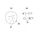
また、嵌合部材3…,14…,26…,44…,53…は必ずしも弾性材料製のものとする必要はなく、上記弾性材料よりも硬度の高い材料により製作することができる。
図23(a)に示した嵌合部材60は、図23(b)に示したパイプ状や中空球状に形成された数ミリ程度の大きさのプラスチック製充填材61…を袋材に多数充填して、上記窓孔2…,13…,25…,43,52に収容できる程度の大きさとしたもので、それは内部の充填材61…を流動させることにより自在に変形させることができるが、一つ一つの充填材61は押圧されてもほとんど弾性変形しない。
【0069】
したがって、上記第1〜4実施形態の褥瘡防止クッションc,d,g,jの使用時において身体が過度に沈下してしまう場合、あるいは上記第5,6実施形態の枕n,pの使用時において頭部が過度に沈下してしまう場合に、この嵌合部材60…を患部以外の位置に当接するように窓孔2…,13…,25…,43,52に嵌合させておくことにより、過度の沈下を防ぐことができる。
【0070】
【発明の効果】
以上述べたところから明らかなように、本発明寝具類は、緩衝体をカバーに収容してなるので、通常は各種の椅子に座ったり、床やベッドに横たわったりするときに、マット,座布団あるいは枕として使用することができる。
また、緩衝体が主体部の上下面に貫通させて形成した窓孔に、嵌合部材を取り外し自在に嵌合させてなるので、上記緩衝体が患部に当接しないように、患部に対応する位置の上記嵌合部材を取り外して窓孔を開口させることができる。
したがって褥瘡の発生の防止,その悪化の防止あるいは腫部等の患部の保護等に効果的である。
【0071】
さらに、上記緩衝体の下側に底敷材を収容すれば、緩衝作用を高めることができる。その底敷材は上記窓孔の底を塞ぐ状態となるので、所要位置の嵌合部材を取り外して使用している場合において、緩衝体が体重等で極度に圧潰されたときにもなお、所要の緩衝作用をする。
【図面の簡単な説明】
【図1】 本発明の第1実施形態の褥瘡防止クッションの斜視図である。
【図2】 図1のI−I線縦断端面図である。
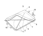
【図3】 本実施形態のカバーの斜視図である。
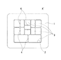
【図4】 本実施形態の緩衝体の斜視図である。
【図5】 緩衝体の他の例の平面図である。
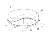
【図6】 本発明の第2実施形態の褥瘡防止クッションの斜視図である。
【図7】 図6のII−II線縦断端面図である。
【図8】 本実施形態のカバーの斜視図である。
【図9】 本実施形態の緩衝体の斜視図である。
【図10】 本発明の第3実施形態の褥瘡防止クッションの斜視図である。
【図11】 図10のIII−III線縦断端面図である。
【図12】 本実施形態のカバーの斜視図である。
【図13】 本実施形態の緩衝体の斜視図である。
【図14】 本発明の第4実施形態の褥瘡防止クッションの縦断端面図である。
【図15】 底敷材の斜視図である。
【図16】 本発明の第5実施形態の枕の斜視図である。
【図17】 図16のIV−IV線縦断端面図である。
【図18】 本実施形態のカバーに底敷材を収容した状態の斜視図である。
【図19】 本実施形態の緩衝体の主体部の斜視図である。
【図20】 上記主体部に嵌合部材を嵌合させてなる緩衝体の斜視図である。
【図21】 本発明の第6実施形態の枕の斜視図である。
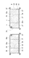
【図22】 図21のV−V線縦断端面図である。
【図23】 (a)は嵌合部材の他の例の斜視図、(b)はその嵌合部材に充填される充填材の拡大斜視図である。
【符号の説明】
a,a′,e,h,k,q 緩衝体
b,f,i,m,s カバー
c,d,g,j 褥瘡防止クッション
n,p 枕
1,12,23,42,51 主体部
2,13,25,43,52 窓孔
3,14,26,44,53,60 嵌合部材
40,46,55 底敷材[0001]
BACKGROUND OF THE INVENTION
The present invention relates to bedding such as futons, mattresses, pillows, and cushions.
[0002]
[Prior art]
Pressure ulcers (so-called floor rubs) can occur when certain parts of the body are pressed for an extended period of time when the posture cannot be changed frequently on a bed or chair.
As a kind of bedding for preventing this pressure ulcer, a donut-shaped cushion made of an annular buffer is known.
It is recognized that this cushion can prevent the occurrence or deterioration of pressure ulcers by buffering the body pressure applied to a specific part of the body, particularly the affected part, by the buffer body (see, for example, Patent Document 1).
[0003]
[Patent Document 1]
Registered Utility Model No. 3031011 (Figs. 1 and 3)
[0004]
[Problems to be solved by the invention]
However, even if the affected area has a required buffering action on the buffer body, it may feel pain when it comes into contact with the buffer body. However, in the donut-shaped cushion, the affected area is formed in the central hole. Unless it is used in a matching state, it is inconvenient in use because it must be brought into contact with the affected part in other parts.
[0005]
Further, even with a futon or mattress that does not have a central hole such as the cushion described above, the buffer body has to come into contact with the entire affected area, and there is a similar inconvenience.
[0006]
Furthermore, even with pillows equipped with a required cushion, there may be a problem in that if there is an affected part such as a tumor in the head, it is inevitable that the affected part is compressed.
[0007]
Accordingly, an object of the present invention is to provide a bedding that solves the above inconvenience and prevents the buffer from coming into contact with the affected area.
[0008]
[Means for Solving the Problems]
According to the first aspect of the present invention, the bedding of the present invention has a locking means 5, 16, 27 on the lower surface of each of the plurality of
[0009]
According to a second aspect of the present invention, a plurality of beddings according to the present invention have a
[0010]
According to a third aspect of the present invention, the bedding of the present invention relates to the lower surface of the
[0011]
DETAILED DESCRIPTION OF THE INVENTION
Hereinafter, as a first embodiment of the present invention, a pressure ulcer prevention cushion which is a kind of bedding will be described in detail with reference to FIGS.
[0012]
a is made of an elastic material such as sponge and is formed in a thick rectangular plate-like
[0013]
The fitting
[0014]
On the lower surface of the
[0015]
The number, size, and shape of the
[0016]
b is a cover made of a flexible material such as fabric or leather, more preferably a stretchable material that can stretch in any direction, and the pressure ulcer prevention cushion c of the present embodiment accommodates the buffer body a in the cover b. It will be.
[0017]
The cover b superposes a substantially rectangular
[0018]
The outer peripheral edge of the
The pressure ulcer prevention cushion c can be tied to a chair or the like by passing another cord or the like through the
The position and number of attachments can be changed as appropriate. For example, the required number may be attached to all four sides of the
[0019]
On the upper surface of the
[0020]
In order to accommodate the buffer body a in the cover b, the latter receiving
[0021]
The pressure ulcer prevention cushion c having the above-described structure can be laid and used as a mat or a cushion when lying down or sitting on a floor, a bed, or various chairs in the accommodated state. It is important that the
Further, if the
[0022]
Next, as a second embodiment of the present invention, a pressure ulcer prevention cushion, which is a type of bedding, will be described with reference to FIGS.
The pressure ulcer prevention cushion d of the present embodiment is different from the pressure ulcer prevention cushion c described above in that its shape is a disk shape.
[0023]
e is made of an elastic material such as sponge and is formed by passing a plurality of circular window holes 13 through the upper and lower surfaces of the
[0024]
The
[0025]
On the lower surface of the
The number, size, and shape of the window holes 13 and the
[0026]
f is a cover made of a flexible material such as fabric or leather, more preferably a stretchable material, and the pressure ulcer prevention cushion d of the present embodiment is formed by housing the buffer e in the cover f.
[0027]
The cover f superimposes a substantially circular
[0028]
The outer peripheral edge of the
[0029]
On the upper surface of the
[0030]
In order to accommodate the buffer body e in the cover f, the latter receiving
[0031]
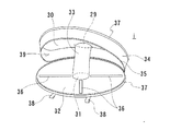
Next, as a third embodiment of the present invention, a pressure ulcer prevention cushion, which is a type of bedding, will be described with reference to FIGS.
The pressure ulcer prevention cushion g of the present embodiment is different from the pressure ulcer prevention cushion d of the second embodiment in that it has a donut shape with a through hole formed in the center.
[0032]
h is a circular
The
[0033]
Each of the window holes 25 may be fitted with one fitting
The
[0034]
On the lower surface of the
Further, an
[0035]
The number, size, and shape of the window holes 25 and the
[0036]
i is a
The
[0037]
The outer
[0038]
The cover i is in a state in which the center holes 29 and 31 of the upper and
[0039]
In order to accommodate the buffer h in the cover i, the former
[0040]
Next, as a fourth embodiment of the present invention, a pressure ulcer prevention cushion, which is a type of bedding, will be described with reference to FIGS.
The pressure ulcer prevention cushion j of the present embodiment is different from the pressure ulcer prevention cushion c of the first embodiment in that the receiving
[0041]
[0042]
The
Further, since the
[0043]
Further, if the upper surface of the floor covering 40 is made of a material such as French pile that can directly engage the hanging
[0044]
It is obvious that the
[0045]
Next, as a fifth embodiment of the present invention, a pillow that is a kind of bedding will be described with reference to FIGS.
k is a buffer formed by fitting a plurality of
The
[0046]
A single
The
[0047]
On the lower surface of each of the
[0048]
The number, size, and shape of the
[0049]
[0050]
m is a cover made of a flexible material such as fabric or leather, more preferably a stretchable material that can be stretched in any direction, and the pillow n of the present embodiment includes the cushion k and the floor covering 46 in the cover m. It is housed in.
[0051]
The cover m superposes a substantially rectangular
[0052]
The buffer m and the
[0053]
The pillow n having the above-described configuration is configured such that the
Further, if the
[0054]
If French pile or the like is used as the material of the upper surface of the
[0055]
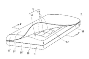
Next, as a sixth embodiment of the present invention, a pillow which is also a kind of bedding will be described with reference to FIGS.
The pillow p of the present embodiment is different from the pillow n of the fifth embodiment in that an auxiliary buffer is housed under the floor covering material.
[0056]
q is a buffer formed by fitting a plurality of
The
[0057]
A single
The
[0058]
On the lower surface of each of the
[0059]
The number, size, and shape of the
[0060]
r is a thick auxiliary buffer made of an elastic material such as sponge, similar to the buffer q, having a flat rectangular shape and a flat semi-elliptical shape when viewed from the left and right side surfaces.
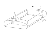
[0061]
55 is a rectangular bottom material in which an elastic material such as a thin sponge is included between flexible materials on the upper and lower surfaces in the same manner as the
The
[0062]
s is a cover made of a flexible material such as fabric or leather, more preferably a stretchable material that can be stretched in any direction, and the pillow p of the present embodiment is composed of the buffer body q, the auxiliary buffer body r, and the bottom pad. The
[0063]
The cover s is formed by superposing a substantially rectangular
[0064]
The buffer s, the auxiliary buffer r and the
[0065]
Since the pillow p of the said structure accommodates the auxiliary buffer body r in the lower side, it becomes the thing which improved the buffering effect rather than the pillow of the said 5th Embodiment.
The pillow p is normally used with the cushion q on the upper side, and by removing the
[0066]
If a French pile or the like is used as the material for the top surface of the
[0067]
In each embodiment described above, it is also preferable to provide a large number of irregularities on the upper surfaces of the buffer bodies a, a ′, e, h, k, and p and the lower surface of the auxiliary buffer body q. This unevenness can reduce the user's feeling of pressure, and can release heat and moisture.
[0068]
Further, the
The
[0069]
Therefore, when the body sinks excessively when using the pressure ulcer prevention cushions c, d, g, j of the first to fourth embodiments, or when using the pillows n, p of the fifth and sixth embodiments. In this case, when the head part sinks excessively, the
[0070]
【The invention's effect】
As is clear from the above description, the bedclothes of the present invention are formed by accommodating the cushioning body in the cover. Therefore, when sitting on various chairs or lying on the floor or bed, mats, cushions or pillows are usually used. Can be used as
Further, since the fitting member is detachably fitted into the window hole formed by penetrating the buffer body through the upper and lower surfaces of the main body portion, it corresponds to the affected part so that the buffer body does not contact the affected part. The window hole can be opened by removing the fitting member at the position.
Therefore, it is effective in preventing the occurrence of pressure ulcer, preventing its deterioration or protecting the affected area such as a tumor.
[0071]
Furthermore, if the floor covering material is accommodated under the buffer body, the buffering action can be enhanced. Since the bottom covering material is in a state of closing the bottom of the window hole, when the buffer member is extremely crushed by weight or the like when the fitting member at the required position is removed and used, it is still necessary. It acts as a buffer.
[Brief description of the drawings]
FIG. 1 is a perspective view of a pressure ulcer prevention cushion according to a first embodiment of the present invention.
FIG. 2 is a longitudinal end view taken along the line II of FIG.
FIG. 3 is a perspective view of a cover according to the present embodiment.
FIG. 4 is a perspective view of a shock absorber according to the present embodiment.
FIG. 5 is a plan view of another example of the shock absorber.
FIG. 6 is a perspective view of a pressure ulcer prevention cushion according to a second embodiment of the present invention.
7 is a longitudinal end view taken along the line II-II in FIG. 6;
FIG. 8 is a perspective view of a cover according to the present embodiment.
FIG. 9 is a perspective view of a shock absorber according to the present embodiment.
FIG. 10 is a perspective view of a pressure ulcer prevention cushion according to a third embodiment of the present invention.
11 is a longitudinal end view taken along line III-III in FIG.
FIG. 12 is a perspective view of a cover according to the present embodiment.
FIG. 13 is a perspective view of a shock absorber according to the present embodiment.
FIG. 14 is a longitudinal end view of a pressure ulcer prevention cushion according to a fourth embodiment of the present invention.
FIG. 15 is a perspective view of a bottom material.
FIG. 16 is a perspective view of a pillow according to a fifth embodiment of the present invention.
FIG. 17 is a vertical end view taken along line IV-IV in FIG. 16;
FIG. 18 is a perspective view of a state in which the bottom material is accommodated in the cover of the present embodiment.
FIG. 19 is a perspective view of a main portion of the shock absorber according to the present embodiment.
FIG. 20 is a perspective view of a shock absorber in which a fitting member is fitted to the main part.
FIG. 21 is a perspective view of a pillow according to a sixth embodiment of the present invention.
22 is a longitudinal end view taken along line VV in FIG. 21. FIG.
23A is a perspective view of another example of the fitting member, and FIG. 23B is an enlarged perspective view of the filler filled in the fitting member.
[Explanation of symbols]
a, a ′, e, h, k, q buffer
b, f, i, m, s cover
c, d, g, j Anti-decubitus cushion
n, p pillow
1, 12, 23, 42, 51 Main part
2,13,25,43,52 Window hole
3, 14, 26, 44, 53, 60 Fitting member
40, 46, 55 Bottom material
Claims (3)
Priority Applications (2)
| Application Number | Priority Date | Filing Date | Title |
|---|---|---|---|
| JP2002338504A JP3733552B2 (en) | 2002-11-21 | 2002-11-21 | Bedding |
| US10/425,865 US6848136B2 (en) | 2002-11-21 | 2003-04-30 | Bedding |
Applications Claiming Priority (1)
| Application Number | Priority Date | Filing Date | Title |
|---|---|---|---|
| JP2002338504A JP3733552B2 (en) | 2002-11-21 | 2002-11-21 | Bedding |
Publications (2)
| Publication Number | Publication Date |
|---|---|
| JP2004167099A JP2004167099A (en) | 2004-06-17 |
| JP3733552B2 true JP3733552B2 (en) | 2006-01-11 |
Family
ID=32701722
Family Applications (1)
| Application Number | Title | Priority Date | Filing Date |
|---|---|---|---|
| JP2002338504A Expired - Fee Related JP3733552B2 (en) | 2002-11-21 | 2002-11-21 | Bedding |
Country Status (1)
| Country | Link |
|---|---|
| JP (1) | JP3733552B2 (en) |
Families Citing this family (1)
| Publication number | Priority date | Publication date | Assignee | Title |
|---|---|---|---|---|
| JP7442231B1 (en) | 2023-02-15 | 2024-03-04 | 株式会社レーベン | Cushioning material, and mattresses, cushions, and pillows containing the cushioning material |
Family Cites Families (3)
| Publication number | Priority date | Publication date | Assignee | Title |
|---|---|---|---|---|
| JPS6194015U (en) * | 1984-11-22 | 1986-06-17 | ||
| JPH03120857U (en) * | 1990-03-22 | 1991-12-11 | ||
| JP2001161505A (en) * | 1999-12-08 | 2001-06-19 | Otsuka Chem Co Ltd | Mattress core and mattress |
-
2002
- 2002-11-21 JP JP2002338504A patent/JP3733552B2/en not_active Expired - Fee Related
Also Published As
| Publication number | Publication date |
|---|---|
| JP2004167099A (en) | 2004-06-17 |
Similar Documents
| Publication | Publication Date | Title |
|---|---|---|
| US5363524A (en) | Multi-adjustment cervical pillow | |
| US7930779B2 (en) | Mattress cover | |
| US6848136B2 (en) | Bedding | |
| US20110047710A1 (en) | Mattress | |
| US7246391B2 (en) | Prayer pillow | |
| JPS63139550A (en) | Mattress | |
| JP5025479B2 (en) | Futon mattress | |
| US12551037B2 (en) | Pillow system | |
| US20020194676A1 (en) | Modular household fabric product with a cover mounted removably on a side surface of a bag | |
| JP3733552B2 (en) | Bedding | |
| US20160128489A1 (en) | Rotatable Mattress | |
| JP7441548B2 (en) | bedding set | |
| KR20100006316U (en) | Beddings and cushions, sofa mats and chair mats for long-term elasticity using the airbag effect | |
| JP3094228U (en) | Pressure ulcer prevention cushion | |
| WO2024055562A1 (en) | Balance mattress, elastic mattress, and furniture | |
| KR20240053297A (en) | Multipurpose Ped Capable of Utilizing Both Faces | |
| KR20190001062U (en) | Foldable mattress | |
| JP3094227U (en) | Pressure ulcer prevention cushion | |
| JP4093357B2 (en) | Pressure ulcer prevention cushion | |
| EP1316280B1 (en) | Household textile environmental protection bag | |
| JP2005110872A (en) | Mattress equipment | |
| JPH0434749Y2 (en) | ||
| KR200495419Y1 (en) | Mattress bedding with hygiene function | |
| JP5602934B1 (en) | Mattress for bedding | |
| JP2005253514A (en) | Cushion device |
Legal Events
| Date | Code | Title | Description |
|---|---|---|---|
| A131 | Notification of reasons for refusal |
Free format text: JAPANESE INTERMEDIATE CODE: A131 Effective date: 20050608 |
|
| A521 | Written amendment |
Free format text: JAPANESE INTERMEDIATE CODE: A523 Effective date: 20050803 |
|
| TRDD | Decision of grant or rejection written | ||
| A01 | Written decision to grant a patent or to grant a registration (utility model) |
Free format text: JAPANESE INTERMEDIATE CODE: A01 Effective date: 20050920 |
|
| A61 | First payment of annual fees (during grant procedure) |
Free format text: JAPANESE INTERMEDIATE CODE: A61 Effective date: 20051006 |
|
| R150 | Certificate of patent (=grant) or registration of utility model |
Free format text: JAPANESE INTERMEDIATE CODE: R150 |
|
| FPAY | Renewal fee payment (prs date is renewal date of database) |
Free format text: PAYMENT UNTIL: 20081028 Year of fee payment: 3 |
|
| FPAY | Renewal fee payment (prs date is renewal date of database) |
Free format text: PAYMENT UNTIL: 20091028 Year of fee payment: 4 |
|
| LAPS | Cancellation because of no payment of annual fees |