JP3733254B2 - Method for assembling image forming apparatus - Google Patents
Method for assembling image forming apparatus Download PDFInfo
- Publication number
- JP3733254B2 JP3733254B2 JP34752798A JP34752798A JP3733254B2 JP 3733254 B2 JP3733254 B2 JP 3733254B2 JP 34752798 A JP34752798 A JP 34752798A JP 34752798 A JP34752798 A JP 34752798A JP 3733254 B2 JP3733254 B2 JP 3733254B2
- Authority
- JP
- Japan
- Prior art keywords
- contact
- toner
- intermediate transfer
- transfer belt
- image
- Prior art date
- Legal status (The legal status is an assumption and is not a legal conclusion. Google has not performed a legal analysis and makes no representation as to the accuracy of the status listed.)
- Expired - Fee Related
Links
Images


Description
【0001】
【発明の属する技術分野】
本発明は、プリンタ、ファクシミリ、プリンター等の画像形成装置及びこれの組立方法に係り、詳しくは、画像形成粒子の集合体である粒子像を担持する粒子像担持体と、該粒子像担持体に当接する当接部材とを備える画像形成装置及びこれの組立方法に関するものである。
【0002】
【従来の技術】
従来、この種の画像形成装置としては、当接部材を有するクリーニング装置を備え、粒子像担持体である潜像担持体や中間転写体等に付着している画像形成粒子としての残留トナーを、該クリーニング装置で掻き取ってクリーニングするものが知られている。このようなクリーニング装置としては、第1当接部材であるクリーニング部材と、該クリーニング部材を粒子像担持体に当接させるための開口と、該開口と該粒子像担持体との間隙をシールする第2当接部材であるシール部材とを有するものが一般的である。
【0003】
また、粒子像担持体に潤滑剤微粉末を塗布する塗布機構を備える画像形成装置も知られている。この塗布機構は、粒子像担持体に潤滑剤微粉末を塗布して、該粒子像担持体とクリーニング部材との摩擦抵抗を低下させることで、両者の摩擦による該粒子像担持体の損傷を軽減するものである。
【0004】
更に、中間転写体に各色のトナー像を順次重ね合わせて一次転写し、重ね合わせ後のトナー像を記録部材に二次転写して複数色の画像を形成する画像形成装置においては、クリーニング装置の各当接部材を該中間転写体に接離させるための接離機構を備えるものも知られている。この接離機構は、中間転写体上における重ね合わせ完了前のトナー像と各当接部材との接触を回避させて、該接触により生ずる該トナー像の消失や変形等を解消するためのものである。
【0005】
これら従来の画像形成装置においては、各当接部材における粒子像担持体との非当接面に、多量のトナーを付着・積層させてしまう。そして、積層トナーの量を増加させると、トナーを潜像担持体や中間転写体に逆移行させて画像の地肌部を汚したり(以下、地汚れという)、カラー画像の色彩を乱したりするという問題が生ずる。
【0006】
特に、上記接離機構を備える画像形成装置においては、各当接部材を中間転写体から離間させる際に、各当接部材上の積層トナーを上記開口から飛散させたり、落下させたり、あるいは中間転写体上に移行させたりして種々の問題を生じ易い。例えば、トナーを上記開口から飛散させた場合には、飛散トナーを、潜像担持体や中間転写体の非画像部に付着させたり、記録部材の搬送用部材に付着させたりして、該記録部材に地汚れや裏汚れを発生させてしまう。また、トナーを上記開口から落下させた場合、落下トナーを受けるためトナートレイ上でトナーを飛散させて、同様の地汚れや裏汚れを発生させてしまう。また、トナーを中間転写体上に移行させた場合には、移行トナーを潜像担持体と中間転写体との当接により形成されるニップ部に滞留させ、該ニップ部でこの移行トナーを後続のトナー像に付着させて画像品質を低下させてしてしまう。
【0007】
【発明が解決しようとする課題】
ところで、上記塗布機構と上記接離機構とを備える画像形成装置においては、装置組立直後の初期の画像形成時に上記積層トナーを顕著に生ずるものの、作像回数の増加に伴って該積層トナーの量を徐々に減少させる傾向がある。そして、作像回数の増加に伴って上述した各問題を起こし難くなるという不可解な現象が生じていた。具体的には、この種の画像形成装置では、転写紙300枚程度に対する作像動作を行った後には、上述した各問題を起こし難くなる。そこで、本発明者はこのような不可解な現象が生ずる原因を解明すべく鋭意研究を重ねた結果、この原因を次のように見出した。即ち、上記塗布機構から飛散した潤滑剤微粉末や、中間転写ベルトからの掻き取りにより飛散した潤滑剤微粉末は、画像形成装置の作像動作に伴ってクリーニング部材やシール部材に付着していき、これら当接部材とトナーとの接着性を徐々に低下させる。そして、このように接着性を徐々に低下させることで、上記積層トナーの量を徐々に減少させていた。
【0008】
本発明は、以上の背景に鑑みなされたものであり、その目的とするところは、出荷先における最初の画像形成から当接部材に対する画像形成粒子の積層を軽減することができる画像形成装置及びこれの組立方法を提供することである。
【0010】
本発明において、「提供」とは、正常に使用し得る状態での引き渡しを示す概念であり、単なる搬入を示すものではない。例えば、搬入先で提供予定物をセッティングする必要がある場合には、セッティングを完了するまで提供したことにはならない。
【0018】
【課題を解決するための手段】
請求項1の発明は、画像形成粒子の集合体である粒子像を担持する粒子像担持体と、該粒子像担持体に付着した画像形成粒子をクリーニングするクリーニング装置とを備え、該粒子像担持体と当接してこの表面に付着した粒子像を掻き取って除去するクリーニングブレードと、該クリーニングブレードを該粒子像担持体に当接させるための開口と、鉛直方向下側を向く面を該粒子像担持体に当接させながら該開口と該粒子像担持体との間隙をシールして該開口からの画像形成粒子の飛散を軽減するシール部材と、クリーニングブレード及びシール部材を該粒子像担持体に接離させるための接離機構とを該クリーニング装置に有し、該粒子像を記録部材に転写する画像形成装置の組立方法において、潤滑剤粉末を内包した袋を、上記シール部材における上記粒子像担持体に当接しない面である鉛直方向上側を向く上面に押し当てることで、該袋のメッシュを介して該潤滑剤粉末を該上面に塗布することを特徴とするものである。
【0019】
この組立方法では、画像形成装置の組立時において当接部材に潤滑剤を塗布して、該当接部材と画像形成粒子との接着性を低下させる。このようにして組み立てられた画像形成装置は、出荷先における最初の画像形成から当接部材の粒子積層面に対して画像形成粒子を付着させ難くする。従って、この組立方法によって組み立てられた画像形成装置においては、組立時や出荷時などにおいて当接部材に潤滑剤が塗布されており、出荷先における最初の画像形成に先立って予め該当接部材と画像形成粒子との接着性が低下されている。当接部材に塗布された潤滑剤のうち、粒子像担持体との当接面に塗布されたものは、出荷先で作像動作が開始されると該粒子像担持体との当接により該当接面から離脱して無くなる。一方、粒子積層面である非当接面に塗布されたものは、出荷先で作像動作が開始されても粒子像担持体と当接せずに該非当接面に定着している。このように定着する潤滑剤は、出荷先の最初の画像形成から当接部材の粒子積層面に対して画像形成粒子を付着させ難くする。
また、この組立方法においては、当接部材に対する潤滑剤の塗布作業の効率を向上させる。例えば、当接部材の粒子積層面は粒子像担持体との非当接面であるので、粒子像担持体との当接面に塗布された潤滑剤は粒子積層の軽減化に直接寄与しない。また、上述のように、上記当接面に塗布された潤滑剤は、出荷先における装置の作動によって粒子像担持体と当接して該当接面から離脱・消失する。このため、当接面に対する潤滑剤の塗布作業は、それほど重要ではない。そこで、この組立方法においては、当接部材における粒子像担持体との非当接面に潤滑剤を塗布することで、重要でない作業を省いて塗布作業の効率を向上させる。
【0022】
【発明の実施の形態】
以下、理解をより容易にすべく、本発明を画像形成装置である電子写真方式のプリンタに適用した一実施形態について説明する。
まず、本実施形態に係るプリンタについて説明する。図1は、本実施形態に係るプリンタの概略構成図である。図1において、図示しない書込光学ユニットは、パーソナルコンピュータ等から送信されてくるカラー画像データを光信号に変換して、均一に負極性に帯電された粒子像担持体としての感光体ドラム1に原稿画像に対応したネガ潜像を形成する。上記書込光学ユニットとしては、例えば、半導体レーザと、これの発光及び駆動を制御する図示しない発光駆動制御部と、ポリゴンミラーと、これを回転駆動する回転駆動モータと、f/θレンズと、反射ミラーとから構成されたものなどがある。
【0023】
感光体ドラム1は、図示しない駆動系により矢印Aの方向、即ち反時計回りに回転される。
【0024】
感光体ドラム1の周囲には、上記書込光学ユニットの他、当接装置としての感光体クリーニング装置2と、帯電手段としての帯電チャージャ3と、現像手段としてのリボルバ現像ユニット4と、一次転写ユニット10とが配設されている。感光体クリーニング装置2は、当接部材としてのファーブラシ2a及び感光体クリーニングブレード2bを有し、一次転写後の感光体ドラム1の表面に残留する画像形成粒子としての残留トナーをクリーニングする。
【0025】
リボルバ現像ユニット4は、Bk現像器4aと、C現像器4bと、M現像器4cと、Y現像器4dとを有し、ドラム軸を中心とする回転により各色の現像器を感光体ドラム1と対向する現像ポジションに位置させることができる。これら各色の現像器は、現像剤の汲み上げ及び撹拌を行う図示しない現像パドルと、該現像剤のトナー濃度を検知する図示しないトナー濃度検知センサと、該現像剤を担持して感光体ドラム1の表面に接触させる図示しない現像スリーブとをそれぞれ有している。なお、これら4つの現像器(4a、4b、4c、4d)の内部構造は同様である。
【0026】
これら4つの現像器(4a、4b、4c、4d)に収容されている現像剤は、トナーと磁性キャリアとからなる2成分現像剤であり、該現像剤中のトナーは負極性に帯電されている。各現像器内の現像剤は、現像に伴うトナー消費によってトナー濃度が低下した場合、トナー濃度検知センサによりトナー濃度不足として検知される。そして、この情報が図示しない制御部に送信され、図示しないトナー補給装置のトナーボトルから補給用トナーが供給される。このようにして、現像器内のトナー濃度は、所定の濃度に保たれている。
【0027】
一次転写ユニット10は、中間転写体としての中間転写ベルト11、電荷付与手段としての一次転写バイアスローラ12、これに接続された一次転写電源17、一次転写前除電手段としてのアースローラ13、ベルト駆動手段としての駆動ローラ14、テンションローラ15、転写バックアップローラ16等から構成されている。
【0028】
中間転写ベルト11は、これら各ローラにより張架され、図中時計回りに回転駆動される駆動ローラ14により、矢印方向に無端移動される。駆動ローラ14の駆動モータは図示しない制御手段としての制御部によって駆動制御されている。中間転写ベルト11を張架するすべてのローラは導電性材料で形成されており、一次転写バイアスローラ12以外の各ローラはそれぞれ接地されている。また、一次転写バイアスローラ12は、中間転写ベルト11と感光体ドラム1との当接により形成されるニップ部の一次転写領域よりも、中間転写ベルト11の移動方向下流側に配置されている。
【0029】
一次転写バイアスローラ12には、一次転写電源17によって一次転写バイアスが印加される。また、上記一次転写領域よりも中間転写ベルト11の移動方向上流側には、接地されたアースローラ13が配置されている。これら一次転写バイアスローラ12、アースローラ13によって、中間転写ベルト11は感光体ドラム1に向けて付勢され、上記ニップ部が形成されている。
【0030】
中間転写ベルト11は、表面層、中間層及びベース層からなる多層構造に構成されており、感光体ドラム1に接触する外周面側に表面層が位置し、内周面側にベース層が位置するように配置される。また、上記中間層とベース層との間には、両層を接着するための接着層が介在している。本実施形態における中間転写ベルト11は、上記JIS K 6911の測定方法による体積抵抗率ρVが、1011[Ωcm]程度の中抵抗に調整されている。なお、体積抵抗率ρVが1012[Ωcm]以上の中間転写ベルトを使用すれば、一次転写後の転写チリを効果的に軽減することができるが、二次転写後に該中間転写ベルトを除電する必要がある。このとき、体積抵抗率ρVが1014[Ωcm]以上のものを利用することも可能であるが、耐久性等の面から中間転写ベルトとしては適さない。また、上記中間転写ベルト11の表面層側における表面抵抗率は、1013[Ω/□]程度となるように構成されることが望ましい。
【0031】
また、中間転写ベルト11の裏面における幅方向両端部には、補強部材が設けられている。この補強部材は、ベルトの捻れ等を防止するためのものであるが、この補強部材によって、一次転写の際、中間転写ベルト11の幅方向両端部付近と上記感光体ドラム1との間に隙間が形成されてしまう場合がある。このため、上記ニップ部が形成されている中間転写ベルト11の裏面には、その幅方向両端部付近に当接し、上記隙間の形成を回避するためのバックアップ部材18が設けられている。
【0032】
中間転写ベルト11の周囲には、塗布機構20を有する当接装置としてのベルトクリーニング装置50と、転写手段としての二次転写ユニット60とが設置されている。これらは、図示しない接離機構によって、それぞれ中間転写ベルト11から接離可能となっている。なお、ベルトクリーニング装置50については、後に詳述する。
【0033】
二次転写ユニット60は、一次転写ユニット10の転写バックアップローラ16に対向する二次転写バイアスローラ61と、これに接続された二次転写電源62とから構成されており、図示しない紙搬送装置により、両ローラ間に転写紙100がタイミングを合わせて搬送されてくる。この紙搬送装置は、給紙ローラ、レジストローラ、各サイズの転写紙100を収納する転写紙カセット、OHP用紙や厚紙などを供給するための手差し給紙トレイ、等から構成されている。
【0034】
この転写紙100は、両ローラ間の二次転写領域を通過する際に、その表面に中間転写ベルト11上の重ね合わせトナー像が二次転写された後、定着装置70に搬送される。
【0035】
定着装置70は、所定温度に制御された定着ローラ71と加圧ローラ72とからなる定着ローラ対の間で転写紙100上の未定着トナー像を溶融し、該未定着トナー像の定着を行う。
【0036】
次に、感光体ドラム1上における静電潜像の現像の順序をBk、C、M、Yの順とした場合における現像動作について説明する。なお、この現像動作の順序はこれに限定されるものではない。
【0037】
上記書込光学ユニットは、パーソナルコンピュータ等から送られてくる各色画像情報に基づいて、まず、レーザ光によって感光体ドラム1上にBk潜像を形成する。このBk潜像は、Bk現像器4aからのBkトナーの付着によりBkトナー像に現像される。Bk現像器4aは、Bk潜像を確実に現像すべく、該Bk潜像の先端部分を感光体ドラム1との対向位置である現像位置に到達させる前に、上記現像スリーブを予め回転させておく。これにより、Bk潜像の先端部分を上記現像位置に到達させたときには、上記現像スリーブ上の現像剤を穂立ち状態にすることができるので、Bk潜像全体を確実に現像することができる。また、Bk現像器4aは、Bk潜像の後端部分に対して上記現像位置を通過させた時点で、速やかに現像スリーブ上に担持した現像剤を穂切りして不作動状態となる。このとき、少なくとも次に現像するC潜像の先端部分をBk現像器4aの現像位置に到達させる前に、完全に不作動状態となるようにする。なお、現像剤の穂切りは、Bk現像器4aの現像スリーブが現像動作中の回転方向と逆方向に切替わることで行われる。
【0038】
このように、Bk現像器4aにより感光体ドラム1上に形成されたBkトナー像は、感光体ドラム1と等しい線速で駆動される中間転写ベルト11の表面に一次転写され、この一次転写によりBk工程が終了する。
【0039】
上記Bkトナー像の一次転写と並行して、感光体ドラム1側では次のC工程が開始される。即ち、上記光書き込みユニットは、上記各色画像情報から取得したC画像データに基づいて、レーザ光により所定のタイミングで感光体ドラム1上にC潜像を形成する。このC潜像は、C現像器4bによってCトナー像に現像される。このC現像器4cにおける現像スリーブの回転は、上記Bk潜像後端部分がC現像器4cの現像位置を通過し、且つ、C潜像の先端部分が該現像位置に到達する前に開始される。そして、C現像器4bは、この現像位置に対してC潜像の後端部分を通過させた時点で、Bk現像器4aの場合と同様に、現像スリーブに担持した現像剤の穂切りを行って不作動状態となる。このとき、やはり次のM潜像の先端部分を到達させる前に完全に不作動状態となるようにする。
【0040】
このように現像されて感光体ドラム1上に形成されたCトナー像は、中間転写ベルト11上に一次転写されたBkトナー像に重ね合わせて一次転写される。
【0041】
以後、M工程及びY工程においても、上述したC工程と同様に、それぞれの画像データに基づいて、潜像形成、現像、一次転写が行われる。このようにして、感光体ドラム1上に順次形成されるBk、C、M、Yの各トナー像を中間転写ベルト11上における同一の画像面に重ね合わせて一次転写することで、中間転写ベルト11上には、これら4色を重ね合わせたフルカラートナー像を形成する。
【0042】
なお、少なくとも、中間転写ベルト11上にフルカラートナー像を形成するまでの間、具体的には1色目のBkトナー像を一次転写した後から4色目のYトナー像の一次転写を終了するまでの間は、ベルトクリーニング装置50内の各当接部材を、図示しない接離機構によって中間転写ベルト11から離間させておく。
【0043】
中間転写ベルト11上に一次転写されたトナー像は、転写紙100上に二次転写されるべく、上記二次転写領域に送られる。このとき、二次転写ユニット60の二次転写バイアスローラ61は、通常、フルカラートナー像が転写紙100に転写されるタイミングで、接離機構によって中間転写ベルト11に押圧される。次いで、この二次転写バイアスローラ61には二次転写電源62によって所定値の二次転写バイアスが印加され、上記二次転写領域に二次転写電界が形成される。これにより、中間転写ベルト11上のフルカラートナー像は転写紙100上に転写される。なお、この転写紙100は、図示しない操作パネルで指定されたサイズの転写紙カセットからレジストローラ方向に搬送され、上記二次転写領域に給紙される。このように転写紙100が給紙される際、転写紙100は、上記レジストローラによって中間転写ベルト11上のトナー像の先端部を二次転写領域に到達させるタイミングに合わせて該二次転写領域に給紙される。
【0044】
中間転写ベルト11上の各色合成画像であるフルカラートナー像が一括転写された転写紙100は、その後、上記紙搬送装置によって定着装置70に搬送され、その表面の未定着トナー像が定着された後、図示しないコピートレイに搬出され、スタックされる。
【0045】
一次転写後の感光体ドラム1は、その表面を感光体クリーニングユニット2によってクリーニングされ、図示しない除電手段としての除電ランプによって均一に除電される。また、二次転写後の中間転写ベルト11は、上記接離機構によりベルトクリーニング装置50を押圧されてクリーニングされる。
【0046】
以上、4色フルカラーを得るプリントモードについて説明したが、これ以外の3色プリントモードや2色プリントモードの場合には、使用する色などが異なる以外、上述した4色プリントモードと同様の動作が行われる。また、単色プリントモードの場合には、所定枚数のプリントを終了するまで、その色の現像器の現像剤のみを穂立ちさせて作動状態にしておき、ベルトクリーニング装置50の各当接部材を中間転写ベルト11に接触させたまま、且つ、中間転写ベルト11を感光体ドラム1に接触させたまま、の状態で中間転写ベルト11を往動方向に一定速度で駆動してプリント動作を行うことになる。
【0047】
次に、ベルトクリーニング装置50について詳述する。
図2は、ベルトクリーニング装置50を中間転写ベルト11及び二次転写領域とともに示す模式図である。図示のように、このベルトクリーニング装置50は、潤滑剤微粉末としてのステアリン酸亜鉛粉末を中間転写ベルト11に塗布するための塗布機構20と、中間転写ベルト11上の残留トナーをクリーニングするためのクリーニング部30と、各駆動機構を有する駆動部40とを備えている。
【0048】
塗布機構20は、ブラシ用ブラケット21、軸22、ブラシローラ23、ステアリン酸亜鉛塊24、バネ25、等で構成されている。ブラシ用ブラケット21は、その端部近傍に設けられた軸22によって揺動自在に支持され、反対側の端部にはバネ25が接続されている。そして、その下面に、中間転写ベルト11と当接するブラシローラ23と、ステアリン酸亜鉛塊24とを保持している。ブラシローラ23は、ステアリン酸亜鉛塊24を掻き取って微粉末にしながら中間転写ベルト24に塗布するものである。この塗布により、中間転写ベルト11と後述のクリーニングブレード32との摩擦抵抗を低下させて、両者の摩擦による中間転写ベルト11の損傷を軽減することができる。
【0049】
クリーニング部30は、ブレード用ブラケット31、これの端部に固定されたクリーニング部材としてのクリーニングブレード32、該端部とは反対側の端部に接続されたバネ33、等で構成されている。クリーニングブレード32は、中間転写ベルト11と当接してこの表面に付着した残留トナーを機械的に掻き取って除去するものである。
【0050】
駆動部40は、カム軸41、カム42、回収パイプ43、シール部材44、シール用カム45、トナートレイ46、等から構成されている。当接部材としてのシール部材44は、ベルトクリーニング装置50本体に形成された開口領域Rの下端と、中間転写ベルト11との間に形成される間隙をシールして、ステアリン酸亜鉛粉末やクリーニングブレード32に掻き取られた残留トナーなどの該開口領域Rからの飛散を防いでいる。
【0051】
図3はクリーニングブレード32及びシール部材44と、中間転写ベルト11との当接の状態を示す模式図である。図3において、中間転写ベルト11表面に付着している残留トナーTは、中間転写ベルト11の無端移動により、まずシール部材44と当接する。シール部材44は剛性の低い材料からなり、且つ、図示のように中間転写ベルト11とトレーリング方向で当接しているため、残留トナーTに当接すると容易に変形して中間転写ベルト11上の残留トナー7の殆どを通過させる。但し、極少量の残留トナーTを中間転写ベルト11との当接部よりもベルト移動方向上流側にくさび状に滞留させる。このように滞留した残留トナーTは、やがて図2に示したトナートレイ46に落下して貯留される。シール部材44と中間転写ベルト11との当接部を通過した残留トナーTは、クリーニングブレード32に掻き取られた後、シール部材44の上面に沿ってベルトクリーニング装置50の内部に導かれる。但し、図3に示すように、一部の残留トナーTは、クリーニングブレード32やシール部材44における中間転写ベルト11との非当接面に付着して堆積する。
【0052】
次に、ベルトクリーニング装置50における各当接部材の接離機構について説明する。
図4(a)は、ブレード用ブラケット31の要部を示す斜視図である。図4(a)において、ブレード用ブラケット31は、図示しないクリーニングユニットの側板に支持された軸34によって揺動可能に支持されている。
【0053】
図4(b)は、ブラシ用ブラケット21の要部を示す斜視図である。図示のように、ブラシ用ブラケット21bも、図示しないクリーニングユニットの側板に支持された軸22によって揺動可能に支持されている。軸22には、図示しないクリーニングユニット本体側にある駆動手段からの駆動を受ける入力用ギヤが固定されており、この入力用ギヤの駆動により、ブラシローラ23を回転させるようになっている。詳しくは、上記入力ギヤが、図示しない制御手段のプロセス信号に基づいて駆動されると、アイドルギヤを介してブラシローラ回転ギヤを回転させ、これにより、ブラシローラ23を回転させる。
【0054】
図5(a)は、ブレード用ブラケット31及びブラシ用ブラケット21の揺動端部を、カム軸41とともに示す斜視図である。図示のように、ブラシ用ブラケット21の揺動端部からは2つの突起21aが突出しており、ブレード用ブラケット31の揺動端部中央からは突起31bが突出している。ブラシ用ブラケット21は、2つの突起21aでこの突起31bを挟むようにブレード用ブラケット31の上に重ねて配置されている。このように、2つのブラケット21、31のそれぞれの揺動端部は、一直線上に配置されている。
【0055】
これら揺動端部の下方には、2つの突起21aに2つのブラシ用カム42aを対向させ、且つ、突起31bのにブレード用カム42bを対向させるようにカム軸41が配設されている。2つのブラシ用カム42aと、ブレード用カム42bとは、図5(b)の断面図に示すように、カム軸41上でその周面方向にずれるように配設されている。
【0056】
カム軸41は、図示しないプリンタ本体側の駆動手段に連結され、図中反時計回りに回転されるようになっている。そして、この回転により、2つのブラシ用カム42aと2つの突起21aとを接離させてブラシ用ブラケット21を揺動させたり、ブレード用カム42bと突起31bとを接離させてブレード用ブラケット31を揺動させたりする。このような接離により、図6(a)及び(b)の模式図に示すように、中間転写ベルト11にクリーニングブレード32を接離させたり、図7(a)及び(b)の模式図に示すように、中間転写ベルト11にブラシローラ23を接離させたりすることができる。
【0057】
一方、図3に示したように、シール部材44の一端は、装置カバー部材に設けられた樋状のステー47に固定されている。このステー47の近傍には図示しないシール用カム45が配設されており、ブレード用カム42bと突起31bとの接離と同期してステー47に接離するように構成されている。この接離により、図8に示すように、樋状のステー47が変形し、シール部材44が矢印C方向に揺動して中間転写ベルト11に接離する。そして、同時に、クリーニングブレード32が中間転写ベルト11に接離する。
【0058】
なお、本実施形態のプリンタにおいては、上述のように、中間転写ベルト11上に各色のトナー像を重ね合わせて転写しているときには、ベルトクリーニング装置50内の各当接部材(ブラシローラ23、クリーニングブレード32、シール部材44)を離間させている。そして、この離間により、中間転写ベルト11上における重ね合わせ完了前のトナー像と、これら当接部材との接触を回避させて、該接触により生ずる該トナー像の消失や変形という不具合を解消している。しかしながら、図3に示したように、シール部材44上やクリーニングブレード32上には残留トナーTが堆積しており、シール部材44やクリーニングブレード32と中間転写ベルト11との離間距離が短いと、中間転写ベルト11上の電荷の影響により、堆積トナーTをシール部材44上やクリーニングブレード上から中間転写ベルト11に向けて飛翔させるおそれがある。このように堆積トナーTを飛翔させると、中間転写ベルト11上に付着させてフルカラー画像の色彩を乱したり、地肌部を汚したりという不具合を生ずる。そこで、本実施形態のプリンタにおいては、堆積トナーTをシール部材44上やクリーニングブレード上から中間転写ベルト11上に向けて飛翔させない程度に、シール部材44やクリーニングブレード32と中間転写ベルト11との離間距離Dを長く設定している(図8)。これにより、シール部材44やクリーニングブレード32からの飛翔トナーによるフルカラー画像の色彩の乱れや地汚れを解消している。
【0059】
ところで、このような接離機構を備える画像形成装置においては、ベルトクリーニング装置50の各当接部材を中間転写ベルト11から離間させる際に、各当接部材上の積層トナーTを開口領域R(図2参照)から飛散させたり、落下させたり、あるいは中間転写ベルト11上に移行させたりして種々の問題を生じ易い。例えば、トナーを開口領域Rから飛散させた場合には、飛散トナーを、感光体ドラム1や中間転写ベルト11の非画像部に付着させたり、転写紙100の搬送用部材に付着させたりして、転写紙100に地汚れや裏汚れを発生させてしまう。また、トナーを開口領域Rから落下させた場合、トナートレイ46(図2参照)上でトナーを飛散させて、同様の地汚れや裏汚れを発生させてしまう。また、トナーを中間転写ベルト11に移行させた場合には、移行トナーを上記一次転写領域のニップ部に滞留させ、該ニップ部でこの移行トナーを後続のトナー像に付着させて画像品質を低下させてしてしまう。
【0060】
一方、従来より、本実施形態のように、潤滑剤微粉末を塗布する塗布機構を備えるプリンタにおいては、装置組立直後の初期の画像形成時に積層トナーを顕著に生ずるものの、転写紙300枚程度に対する作像動作を行った後には、堆積トナーを生じ難くなる。本発明者は鋭意研究により、このような現象が生ずる原因を次のように見出した。即ち、クリーニングブレード32の先端やブラシローラ23やから飛散したステアリン酸亜鉛粉末は、プリント動作に伴ってクリーニングブレード32やシール部材44の上記非当接面に付着していき、該非当接面とトナーとの接着性を徐々に低下させる。そして、このように接着性を徐々に低下させることで、積層トナーの量を徐々に減少させていた。従って、塗布機構20は、中間転写ベルト11に対するステアリン酸亜鉛粉末の塗布機能の他、クリーニングブレード32やシール部材44に対するステアリン酸亜鉛粉末の塗布機能をも発揮していたことになる。
【0061】
しかしながら、このように塗布機能を発揮しても、装置搬入・セッティング直後から、転写紙300枚程度のプリント動作を完了するまでの間には、上述した各問題を生ずるおそれがある。そこで、本実施形態のプリンタにおいては、装置搬入・セッティング直後の最初のプリント動作から、各当接部材に対するトナーの堆積を軽減すべく、次のような特徴的な構成を備えている。
【0062】
以下、この特徴的な構成について説明する。
本実施形態のプリンタは、装置の組立時において、クリーニングブレード32及びシール部材44にステアリン酸亜鉛粉末が塗布されており、出荷先における最初のプリント動作に先立って予めこれら当接部材とトナーとの接着性が低下されている。
【0063】
図9はクリーニングブレード32及びシール部材44に対するステアリン酸亜鉛粉末の塗布方法の一例を示す模式図である。図9において、絹などからなり、微小メッシュ構造を有する布袋101は、ステアリン酸亜鉛粉末24aを内包しており、押圧されたり叩かれたりすることにより、該微小メッシュを介して外部にステアリン酸亜鉛粉末24aを飛散させる。このような構成は、例えば、滑り止め剤を塗布するためのロージンバックなどで広く知られている。なお、ステアリン酸亜鉛粉末24aの塗布手段は布袋101に限定されるものではなく、例えばハケなどでもよい。
【0064】
上述のように、クリーニングブレード32やシール部材44におけるトナー積層面は中間転写ベルト11との非当接面である。このため、中間転写ベルト11との当接面に塗布されたステアリン酸亜鉛粉末は、堆積トナーの軽減化には直接寄与しない。また、出荷先でプリント動作が開始されると中間転写ベルト11との当接により当接面から離脱して無くなる。このため、当接面に対するステアリン酸亜鉛粉末24aの塗布作業は、それほど重要ではない。そこで、本実施形態のプリンタにおいては、クリーニングブレード32やシール部材44における中間転写ベルト11との非当接面にのみステアリン酸亜鉛粉末24aが塗布される。このような塗布により、重要でない作業が省略されて塗布作業の効率化が図られる。
【0065】
上記非当接面に塗布されたステアリン酸亜鉛粉末24aは、出荷先でプリント動作が開始されても中間転写ベルト11と当接せずに該非当接面に定着している。このように定着するステアリン酸亜鉛粉末24aは、出荷先の最初のプリント動作から上記非当接面であるトナー堆積面に対してトナーを付着させ難くする。
【0066】
本実施形態のプリンタの塗布機構20は、上述のように、中間転写ベルト11に対するステアリン酸亜鉛粉末の塗布機能の他、クリーニングブレード32やシール部材44に対するステアリン酸亜鉛粉末24aの塗布機能をも発揮する。しかしながら、装置組立時において、上記非当接面にステアリン酸亜鉛が一旦塗布されると、このステアリン酸亜鉛は該非当接面に長期間定着する。このため、本発明に係る画像形成装置において、クリーニングブレード32やシール部材44等の当接部材に対する潤滑剤の塗布機能は必須ではない。但し、このような塗布機能を備えていると、当接部材に対する画像形成粒子の接着性の低減化を永続的に図ることができる。
【0067】
図10は、ステアリン酸亜鉛粉末24aを塗布した後におけるクリーニングブレード32及びシール部材44へのトナーの付着状態を示す模式図である。図示のように、ステアリン酸亜鉛粉末24aの塗布により、クリーニングブレード32やシール部材44の上記非当接面に対するトナーの接着性が低下され、該当接面にトナーが堆積し難くなることがわかる。なお、本実施形態のプリンタのクリーニングブレードは、図2に示したように、垂直に近い状態で中間転写ベルト11に当接しており、ステアリン酸亜鉛粉末24aが塗布されても、中間転写ベルト11との当接部よりもベルト移動方向上流側にトナーを滞留させ易い。しかしながら、このように滞留させても、クリーニングブレードの上記非当接面にステアリン酸亜鉛粉末24aを塗布しているので、クリーニングブレード32にトナーを接触させるだけで、付着させることはない。但し、このようなトナーの滞留は好ましいものではないので、本実施形態のプリンタは、図2におけるブラシローラ23とクリーニングブレード32との間に図面奥行き方向に向かう気流を発生させ、該間においてクリーニングブレード32に接触しているトナーをこの気流により回収するように構成されている。
【0068】
以上、本実施形態のプリンタによれば、出荷先における最初のプリント動作からクリーニングブレード32やシール部材44のトナー堆積面に対してトナーを付着させ難くするので、出荷先における最初のプリント動作からこれら当接部材に対するトナーの堆積を軽減することができる。
【0069】
また、装置組立の工程において、クリーニングブレード32やシール部材44に対するステアリン酸亜鉛粉末24aの塗布作業の効率化を図ることができるので、装置の製造コストが低減することができる。
【0070】
なお、本実施形態において、クリーニングブレード32やシール部材44に対して潤滑剤としてステアリン酸亜鉛粉末を塗布した構成のプリンタについて説明したが、本発明に係る画像形成装置に使用する潤滑剤はこれに限られるものではない。
【0071】
また、クリーニングブレード32やシール部材44に対して、装置の組立時に潤滑剤を塗布したプリンタについて説明したが、少なくとも装置をユーザに提供する前に潤滑剤を塗布すればよく、例えば、装置の出荷時や、出荷先におけるセッティング時などに塗布してもよい。
【0072】
また、本発明に係る当接装置はクリーニング装置に限定されるものではなく、例えば当接部材として塗布部材、紙搬送ローラ、転写バイアスローラ、転写バックアップローラ等を備える潤滑剤塗布専用装置、紙搬送装置、転写バイアス装置、転写バックアップ装置等についても本発明の適用が可能である。
【0077】
【発明の効果】
請求項1の発明によれば、出荷先における最初の画像形成から当接部材の粒子積層面に対して画像形成粒子を付着させ難くするので、出荷先における最初の画像形成から該当接部材に対する画像形成粒子の積層を軽減することができるという優れた効果がある。
また、当接部材に対する潤滑剤の塗布作業の効率を向上させるので、装置の製造コストを低減することができるという優れた効果がある。
【図面の簡単な説明】
【図1】実施形態に係るプリンタの概略構成図。
【図2】同プリンタのベルトクリーニング装置50を中間転写ベルト11及び二次転写領域とともに示す模式図。
【図3】同ベルトクリーニング装置50のクリーニングブレード32及びシール部材44と、中間転写ベルト11との当接の状態を示す模式図。
【図4】(a)は同ベルトクリーニング装置50のブレード用ブラケット31の要部を示す斜視図。
(b)は同ベルトクリーニング装置50のブラシ用ブラケット21の要部を示す斜視図。
【図5】(a)は同ブレード用ブラケット31及びブラシ用ブラケット21の揺動端部をカム軸41とともに示す斜視図。
(b)は同カム軸41を示す断面図。
【図6】(a)及び(b)は同中間転写ベルト11に対する同クリーニングブレード32の接離状態を示す模式図。
【図7】(a)及び(b)は同中間転写ベルト11に対するブラシローラ23の接離状態を示す模式図。
【図8】同中間転写ベルト11からの同シール部材44及び同クリーニングブレード32の離間状態を説明する模式図。
【図9】同クリーニングブレード32及び同シール部材44に対するステアリン酸亜鉛粉末の塗布方法の一例を示す模式図。
【図10】ステアリン酸亜鉛粉末24aを塗布した後における同クリーニングブレード32及び同シール部材44へのトナーの付着状態を示す模式図。
【符号の説明】
1 感光体ドラム
2 感光体クリーニング装置
2a ファーブラシ
2b 感光体クリーニングブレード
3 帯電チャージャ3
4 リボルバ現像ユニット4
4a Bk現像器
4b C現像器
4c M現像器
4d Y現像器
10 一次転写ユニット
11 中間転写ベルト
12 一次転写バイアスローラ
13 アースローラ
14 駆動ローラ
15 テンションローラ
16 転写バックアップローラ
17 一次転写電源
20 塗布機構
21 ブラシ用ブラケット
21a 突起
22 軸
23 ブラシローラ
24 ステアリン酸亜鉛塊
24a ステアリン酸亜鉛粉末
30 クリーニング部
31 ブレード用ブラケット
31b 突起
32 クリーニングブレード
33 バネ
40 駆動部
41 カム軸
42 カム
42a ブラシ用カム
42b ブレード用カム
43 回収パイプ
44 シール部材
45 シール用カム
46 トナートレイ
47 ステー
50 ベルトクリーニング装置
60 二次転写ユニット
61 二次転写バイアスローラ
62 二次転写電源
70 定着装置
71 定着ローラ
72 加圧ローラ
100 転写紙
101 布袋[0001]
BACKGROUND OF THE INVENTION
The present invention relates to an image forming apparatus such as a printer, a facsimile machine, and a printer, and an assembling method thereof. Specifically, the present invention relates to a particle image carrier that carries a particle image that is an aggregate of image forming particles, and a particle image carrier. The present invention relates to an image forming apparatus including an abutting member that abuts and an assembling method thereof.
[0002]
[Prior art]
Conventionally, as this type of image forming apparatus, a cleaning device having an abutting member is provided, and residual toner as image forming particles adhering to a latent image carrier or an intermediate transfer body as a particle image carrier, What cleans by cleaning with this cleaning device is known. As such a cleaning device, a cleaning member as a first contact member, an opening for bringing the cleaning member into contact with the particle image carrier, and a gap between the opening and the particle image carrier are sealed. What has a sealing member which is a 2nd contact member is common.
[0003]
Also known is an image forming apparatus provided with an application mechanism for applying fine lubricant powder to a particle image carrier. This coating mechanism reduces the frictional resistance between the particle image carrier and the cleaning member by applying a fine powder of lubricant to the particle image carrier, thereby reducing damage to the particle image carrier due to friction between the two. To do.
[0004]
Further, in an image forming apparatus in which toner images of respective colors are sequentially superimposed and primarily transferred onto an intermediate transfer member, and a toner image of the respective colors is secondarily transferred to a recording member to form a plurality of color images, There is also known one provided with a contact / separation mechanism for bringing each contact member into contact with or separated from the intermediate transfer member. This contact / separation mechanism avoids contact between the toner image before completion of superimposition on the intermediate transfer member and each contact member, and eliminates disappearance or deformation of the toner image caused by the contact. is there.
[0005]
In these conventional image forming apparatuses, a large amount of toner adheres and is laminated on the non-contact surface of each contact member with the particle image carrier. When the amount of the laminated toner is increased, the toner is reversely transferred to the latent image carrier or the intermediate transfer member, and the background portion of the image is stained (hereinafter referred to as background contamination), or the color of the color image is disturbed. The problem arises.
[0006]
In particular, in an image forming apparatus having the contact / separation mechanism, when the contact members are separated from the intermediate transfer member, the laminated toner on the contact members is scattered from the opening, dropped, or intermediate. Various problems are likely to occur due to transfer onto the transfer body. For example, when toner is scattered from the opening, the scattered toner is attached to a non-image portion of a latent image carrier or an intermediate transfer member, or attached to a conveyance member of a recording member, and the recording is performed. This will cause dirt and back dirt on the member. Further, when the toner is dropped from the opening, the toner is scattered on the toner tray to receive the dropped toner, and the same background dirt and back dirt are generated. In addition, when the toner is transferred onto the intermediate transfer member, the transfer toner is retained in a nip portion formed by the contact between the latent image carrier and the intermediate transfer member, and the transferred toner is followed by the nip portion. The toner image adheres to the toner image and deteriorates the image quality.
[0007]
[Problems to be solved by the invention]
By the way, in an image forming apparatus provided with the coating mechanism and the contact / separation mechanism, the laminated toner is remarkably generated during the initial image formation immediately after the assembly of the apparatus, but the amount of the laminated toner increases as the number of image formation increases. Tend to decrease gradually. And the mysterious phenomenon that it becomes difficult to raise each problem mentioned above with the increase in the number of times of image formation has arisen. Specifically, in this type of image forming apparatus, after performing an image forming operation on about 300 transfer sheets, it is difficult to cause the above-described problems. Therefore, as a result of intensive studies to elucidate the cause of such an inexplicable phenomenon, the present inventor found the cause as follows. That is, the lubricant fine powder scattered from the coating mechanism and the lubricant fine powder scattered by scraping off from the intermediate transfer belt adhere to the cleaning member and the seal member in accordance with the image forming operation of the image forming apparatus. The adhesiveness between these contact members and the toner is gradually reduced. The amount of the laminated toner is gradually decreased by gradually decreasing the adhesiveness in this way.
[0008]
The present invention has been made in view of the above background, and an object of the present invention is to provide an image forming apparatus capable of reducing the stacking of image forming particles on the contact member from the initial image formation at the shipping destination, and the image forming apparatus. An assembly method is provided.
[0010]
In the present invention, “providing” is a concept indicating delivery in a state where it can be normally used, and does not indicate mere delivery. For example, when it is necessary to set a provision object at the delivery destination, it is not provided until the setting is completed.
[0018]
[Means for Solving the Problems]
The invention according to
[0019]
In this assembling method, a lubricant is applied to the contact member at the time of assembling the image forming apparatus, thereby reducing the adhesion between the corresponding contact member and the image forming particles. The image forming apparatus assembled in this way makes it difficult for image forming particles to adhere to the particle lamination surface of the contact member from the first image formation at the shipping destination.Therefore, in the image forming apparatus assembled by this assembling method, the lubricant is applied to the contact member at the time of assembling or shipping, and the contact member and the image are preliminarily formed before the first image formation at the shipping destination. Adhesion with the formed particles is reduced. Of the lubricants applied to the contact member, those applied to the contact surface with the particle image carrier are subject to contact with the particle image carrier when the image forming operation is started at the shipping destination. Disengage from the contact surface and disappear. On the other hand, the material applied to the non-contact surface which is the particle lamination surface is fixed to the non-contact surface without contacting the particle image carrier even when the image forming operation is started at the shipping destination. The lubricant thus fixed makes it difficult for image forming particles to adhere to the particle lamination surface of the contact member from the initial image formation at the shipping destination.
Further, in this assembling method, the efficiency of the operation of applying the lubricant to the contact member is improved. For example, since the particle lamination surface of the contact member is a non-contact surface with the particle image carrier, the lubricant applied to the contact surface with the particle image carrier does not directly contribute to the reduction of particle lamination. Further, as described above, the lubricant applied to the contact surface comes into contact with the particle image carrier by the operation of the apparatus at the shipping destination, and is detached from the contact surface and disappears. For this reason, the operation of applying the lubricant to the contact surface is not so important. Therefore, in this assembling method, the lubricant is applied to the non-contact surface of the contact member with the particle image carrier, thereby eliminating the unimportant work and improving the efficiency of the application work.
[0022]
DETAILED DESCRIPTION OF THE INVENTION
In order to facilitate understanding, an embodiment in which the present invention is applied to an electrophotographic printer as an image forming apparatus will be described below.
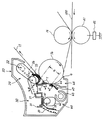
First, the printer according to this embodiment will be described. FIG. 1 is a schematic configuration diagram of a printer according to the present embodiment. In FIG. 1, a writing optical unit (not shown) converts color image data transmitted from a personal computer or the like into an optical signal and applies it to a
[0023]
The
[0024]
Around the
[0025]
The
[0026]
The developer accommodated in these four developing units (4a, 4b, 4c, 4d) is a two-component developer composed of toner and a magnetic carrier, and the toner in the developer is negatively charged. Yes. The developer in each developing device is detected as a toner concentration shortage by a toner concentration detection sensor when the toner concentration decreases due to toner consumption accompanying development. Then, this information is transmitted to a control unit (not shown), and supply toner is supplied from a toner bottle of a toner supply device (not shown). In this way, the toner density in the developing device is kept at a predetermined density.
[0027]
The
[0028]
The
[0029]
A primary transfer bias is applied to the primary transfer bias
[0030]
The
[0031]
Reinforcing members are provided at both ends in the width direction on the back surface of the
[0032]
Around the
[0033]
The
[0034]
When the
[0035]
The fixing
[0036]
Next, the developing operation when the order of development of the electrostatic latent images on the
[0037]
The writing optical unit first forms a Bk latent image on the
[0038]
As described above, the Bk toner image formed on the
[0039]
In parallel with the primary transfer of the Bk toner image, the next C process is started on the
[0040]
The C toner image thus developed and formed on the
[0041]
Thereafter, also in the M process and the Y process, latent image formation, development, and primary transfer are performed based on the respective image data as in the above-described C process. In this way, the Bk, C, M, and Y toner images sequentially formed on the
[0042]
At least until the full-color toner image is formed on the
[0043]
The toner image primarily transferred onto the
[0044]
The
[0045]
The surface of the
[0046]
The print mode for obtaining four full colors has been described above. In the other three-color print mode and the two-color print mode, the same operation as the above-described four-color print mode is performed except that the color used is different. Done. In the case of the single color print mode, only the developer of the color developing device is sprinkled and activated until a predetermined number of prints are completed, and each contact member of the
[0047]
Next, the
FIG. 2 is a schematic diagram showing the
[0048]
The
[0049]
The
[0050]
The
[0051]
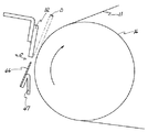
FIG. 3 is a schematic view showing a state in which the
[0052]
Next, the contact / separation mechanism of each contact member in the
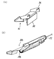
FIG. 4A is a perspective view showing a main part of the
[0053]
FIG. 4B is a perspective view showing a main part of the
[0054]
FIG. 5A is a perspective view showing the swing end portions of the
[0055]
Below these swinging end portions, a
[0056]
The
[0057]
On the other hand, as shown in FIG. 3, one end of the
[0058]
In the printer of this embodiment, as described above, when the toner images of the respective colors are transferred on the
[0059]
By the way, in the image forming apparatus provided with such a contact / separation mechanism, when the contact members of the
[0060]
On the other hand, conventionally, in a printer having an application mechanism for applying a fine lubricant powder as in the present embodiment, although toner is remarkably generated during initial image formation immediately after the assembly of the apparatus, the transfer toner is about 300 sheets of paper. After the image forming operation is performed, accumulated toner is hardly generated. The present inventor has found the cause of such a phenomenon as follows through intensive research. That is, the zinc stearate powder scattered from the tip of the
[0061]
However, even if the application function is exhibited in this manner, the above-described problems may occur immediately after the apparatus is loaded and set and until the printing operation of about 300 transfer sheets is completed. Therefore, the printer according to the present embodiment has the following characteristic configuration in order to reduce toner accumulation on each contact member from the initial printing operation immediately after the apparatus is loaded and set.
[0062]
Hereinafter, this characteristic configuration will be described.
In the printer of this embodiment, zinc stearate powder is applied to the
[0063]
FIG. 9 is a schematic view showing an example of a method of applying zinc stearate powder to the
[0064]
As described above, the toner lamination surface of the
[0065]
The
[0066]
As described above, the
[0067]
FIG. 10 is a schematic diagram showing the state of toner adhering to the
[0068]
As described above, according to the printer of the present embodiment, it is difficult for the toner to adhere to the toner accumulation surface of the
[0069]
Further, in the device assembly process, the efficiency of the operation of applying the
[0070]
In the present embodiment, a printer having a configuration in which zinc stearate powder is applied as a lubricant to the
[0071]
Further, the printer in which the lubricant is applied to the
[0072]
Further, the contact device according to the present invention is not limited to the cleaning device. For example, the lubricant application dedicated device including a coating member, a paper transport roller, a transfer bias roller, a transfer backup roller, and the like as a contact member, a paper transport The present invention can also be applied to a device, a transfer bias device, a transfer backup device, and the like.
[0077]
【The invention's effect】
Claim1According to the invention, since it is difficult for the image forming particles to adhere to the particle lamination surface of the contact member from the first image formation at the shipping destination, the image forming particles from the first image forming at the shipping destination to the corresponding contact member can be prevented. There is an excellent effect that lamination can be reduced.
Moreover, since the efficiency of the application | coating operation | work of the lubricant with respect to a contact member is improved, there exists the outstanding effect that the manufacturing cost of an apparatus can be reduced.
[Brief description of the drawings]
FIG. 1 is a schematic configuration diagram of a printer according to an embodiment.
FIG. 2 is a schematic view showing a
3 is a schematic view showing a state in which the
4A is a perspective view showing a main part of a
FIG. 4B is a perspective view illustrating a main part of the
5A is a perspective view showing the swing end portions of the
FIG. 4B is a cross-sectional view showing the
FIGS. 6A and 6B are schematic views showing the contact state of the
FIGS. 7A and 7B are schematic views showing the contact state of the
FIG. 8 is a schematic diagram for explaining a separation state of the
9 is a schematic view showing an example of a method of applying zinc stearate powder to the
FIG. 10 is a schematic view showing a toner adhesion state on the
[Explanation of symbols]
1 Photosensitive drum
2 Photoconductor cleaning device
2a Fur brush
2b Photoconductor cleaning blade
3 Charger 3
4
4a Bk developer
4b C developer
4c M developer
4d Y developer
10 Primary transfer unit
11 Intermediate transfer belt
12 Primary transfer bias roller
13 Earth Roller
14 Drive roller
15 Tension roller
16 Transfer backup roller
17 Primary transfer power supply
20 Coating mechanism
21 Brush bracket
21a protrusion
22 axes
23 Brush roller
24 Zinc stearate lump
24a Zinc stearate powder
30 Cleaning section
31 Bracket for blade
31b Protrusion
32 Cleaning blade
33 Spring
40 Drive unit
41 camshaft
42 cam
42a Brush cam
42b Blade cam
43 Recovery pipe
44 Sealing member
45 Sealing cam
46 Toner tray
47 stay
50 Belt cleaning device
60 Secondary transfer unit
61 Secondary transfer bias roller
62 Secondary transfer power supply
70 Fixing device
71 Fixing roller
72 Pressure roller
100 transfer paper
101 cloth bag
Claims (1)
潤滑剤粉末を内包した袋を、上記シール部材における上記粒子像担持体に当接しない面である鉛直方向上側を向く上面に押し当てることで、該袋のメッシュを介して該潤滑剤粉末を該上面に塗布することを特徴とする組立方法。A particle image carrier that carries a particle image, which is an aggregate of image forming particles, and a cleaning device that cleans the image forming particles attached to the particle image carrier; A cleaning blade that scrapes and removes the particle image adhering to the particle, an opening for contacting the cleaning blade with the particle image carrier, and a surface facing downward in the vertical direction is brought into contact with the particle image carrier. However, a seal member that seals a gap between the opening and the particle image carrier to reduce scattering of image forming particles from the opening, and a contact for bringing the cleaning blade and the seal member into and out of contact with the particle image carrier. In the assembling method of the image forming apparatus having the separation mechanism in the cleaning device and transferring the particle image to the recording member,
The bag containing therein a lubricant powder, by pressing on the top surface facing the upper side in the vertical direction is a surface not in contact with the particle image bearing member in the sealing member, said the lubricant powder through the mesh of the bag An assembling method comprising applying to an upper surface .
Priority Applications (1)
| Application Number | Priority Date | Filing Date | Title |
|---|---|---|---|
| JP34752798A JP3733254B2 (en) | 1998-12-07 | 1998-12-07 | Method for assembling image forming apparatus |
Applications Claiming Priority (1)
| Application Number | Priority Date | Filing Date | Title |
|---|---|---|---|
| JP34752798A JP3733254B2 (en) | 1998-12-07 | 1998-12-07 | Method for assembling image forming apparatus |
Publications (2)
| Publication Number | Publication Date |
|---|---|
| JP2000172120A JP2000172120A (en) | 2000-06-23 |
| JP3733254B2 true JP3733254B2 (en) | 2006-01-11 |
Family
ID=18390838
Family Applications (1)
| Application Number | Title | Priority Date | Filing Date |
|---|---|---|---|
| JP34752798A Expired - Fee Related JP3733254B2 (en) | 1998-12-07 | 1998-12-07 | Method for assembling image forming apparatus |
Country Status (1)
| Country | Link |
|---|---|
| JP (1) | JP3733254B2 (en) |
Families Citing this family (1)
| Publication number | Priority date | Publication date | Assignee | Title |
|---|---|---|---|---|
| JP6390557B2 (en) * | 2015-08-31 | 2018-09-19 | 京セラドキュメントソリューションズ株式会社 | Cleaning device and image forming apparatus |
-
1998
- 1998-12-07 JP JP34752798A patent/JP3733254B2/en not_active Expired - Fee Related
Also Published As
| Publication number | Publication date |
|---|---|
| JP2000172120A (en) | 2000-06-23 |
Similar Documents
| Publication | Publication Date | Title |
|---|---|---|
| JP3772032B2 (en) | Image forming apparatus | |
| JP3136381B2 (en) | Image forming apparatus having developing means | |
| JP2008139421A (en) | Image forming apparatus and image forming method | |
| JP2007047474A (en) | Image forming apparatus | |
| JPH06124005A (en) | Image forming device | |
| JP3733254B2 (en) | Method for assembling image forming apparatus | |
| US6674987B2 (en) | Image forming apparatus having intermediate transfer bodies, brush roller devices and transfer roll device having defined axial lengths | |
| JP3780110B2 (en) | Contact device and image forming apparatus | |
| JP2000155511A (en) | Image forming device, image forming method, intermediate transfer device and transfer method | |
| JP3695512B2 (en) | Image forming apparatus | |
| JP2002244386A (en) | Image forming device | |
| JP4207469B2 (en) | Image forming apparatus | |
| JP2004117643A (en) | Image forming apparatus | |
| JP2002323803A (en) | Image forming device | |
| JP2004093770A (en) | Color image forming apparatus and method | |
| JP2005037521A (en) | Image forming apparatus | |
| JP2001042735A (en) | Image forming device | |
| JP3877258B2 (en) | Image forming apparatus | |
| JP4054568B2 (en) | Image forming apparatus | |
| JP2000172119A (en) | Image forming device | |
| JP2001201993A (en) | Image forming device | |
| JP2004317994A (en) | Image forming apparatus | |
| JP4340406B2 (en) | Image forming apparatus | |
| JP2007108494A (en) | Cleaning device and image forming apparatus using same | |
| JPH11202728A (en) | Image forming device |
Legal Events
| Date | Code | Title | Description |
|---|---|---|---|
| A977 | Report on retrieval |
Free format text: JAPANESE INTERMEDIATE CODE: A971007 Effective date: 20041222 |
|
| A131 | Notification of reasons for refusal |
Free format text: JAPANESE INTERMEDIATE CODE: A131 Effective date: 20050304 |
|
| A521 | Written amendment |
Free format text: JAPANESE INTERMEDIATE CODE: A523 Effective date: 20050428 |
|
| A131 | Notification of reasons for refusal |
Free format text: JAPANESE INTERMEDIATE CODE: A131 Effective date: 20050527 |
|
| A521 | Written amendment |
Free format text: JAPANESE INTERMEDIATE CODE: A523 Effective date: 20050726 |
|
| TRDD | Decision of grant or rejection written | ||
| A01 | Written decision to grant a patent or to grant a registration (utility model) |
Free format text: JAPANESE INTERMEDIATE CODE: A01 Effective date: 20050916 |
|
| A61 | First payment of annual fees (during grant procedure) |
Free format text: JAPANESE INTERMEDIATE CODE: A61 Effective date: 20051017 |
|
| R150 | Certificate of patent or registration of utility model |
Free format text: JAPANESE INTERMEDIATE CODE: R150 |
|
| FPAY | Renewal fee payment (event date is renewal date of database) |
Free format text: PAYMENT UNTIL: 20081021 Year of fee payment: 3 |
|
| FPAY | Renewal fee payment (event date is renewal date of database) |
Free format text: PAYMENT UNTIL: 20091021 Year of fee payment: 4 |
|
| FPAY | Renewal fee payment (event date is renewal date of database) |
Free format text: PAYMENT UNTIL: 20101021 Year of fee payment: 5 |
|
| FPAY | Renewal fee payment (event date is renewal date of database) |
Free format text: PAYMENT UNTIL: 20111021 Year of fee payment: 6 |
|
| FPAY | Renewal fee payment (event date is renewal date of database) |
Free format text: PAYMENT UNTIL: 20121021 Year of fee payment: 7 |
|
| FPAY | Renewal fee payment (event date is renewal date of database) |
Free format text: PAYMENT UNTIL: 20131021 Year of fee payment: 8 |
|
| LAPS | Cancellation because of no payment of annual fees |