JP3732470B2 - Image processing apparatus, image recording apparatus, and program - Google Patents
Image processing apparatus, image recording apparatus, and program Download PDFInfo
- Publication number
- JP3732470B2 JP3732470B2 JP2002268861A JP2002268861A JP3732470B2 JP 3732470 B2 JP3732470 B2 JP 3732470B2 JP 2002268861 A JP2002268861 A JP 2002268861A JP 2002268861 A JP2002268861 A JP 2002268861A JP 3732470 B2 JP3732470 B2 JP 3732470B2
- Authority
- JP
- Japan
- Prior art keywords
- value
- image
- image data
- quantization
- input
- Prior art date
- Legal status (The legal status is an assumption and is not a legal conclusion. Google has not performed a legal analysis and makes no representation as to the accuracy of the status listed.)
- Expired - Fee Related
Links
Images


Landscapes
- Facsimile Image Signal Circuits (AREA)
- Ink Jet (AREA)
- Particle Formation And Scattering Control In Inkjet Printers (AREA)
- Color, Gradation (AREA)
- Image Processing (AREA)
Description
【0001】
【発明の属する技術分野】
本発明は、多値画像データを高精細かつ高階調に印刷処理するための画像処理装置、画像記録装置(画像形成装置)、及びプログラムに関する。
【0002】
【従来の技術】
スキャナやディジタルカメラ等の入力装置で読み取った多値画像データをプリンタやディスプレイ等の出力装置に出力する画像入出力システムが存在する。その際に、入力装置で読み取った多値(例えば8ビット精度ならば256階調)の画像データを出力装置が出力可能な階調数の画像データに変換し、擬似的に連続階調を表現する方法として、擬似中間調処理というものが存在する。
【0003】
中でも出力装置がドットのON/OFFのみの2値しか表現できないときには2値化処理が従来から行われている。この2値化処理の中で解像性と階調性に共に優れたものとして誤差拡散処理や平均誤差最小法が存在する。誤差拡散法と平均誤差最小法は、誤差の拡散作業をいつ行うかが異なるだけであり、論理的には等価なものである。
【0004】
さらにこの誤差拡散処理を2値だけでなく、3値以上の階調数にも適用したものとして、多値誤差拡散処理が存在する。2値誤差拡散処理と同様に、階調性と解像性に優れた処理が可能である。
【0005】
出力装置における3値以上の階調数を確保するために各種の方式がある。インクジェットプリンタにおいては射出するインク量を制御することにより小・中・大ドットとドット径を変化させる方式、ドットの重ね打ちを行う方式、濃度の異なるインク・濃淡インクを用いる方式等により3値化以上の階調数を再現している。一般的には淡インクの濃度を濃インクの1/2〜1/6に希釈してある。電子写真においては書込みの露光をパルス幅分割して1ドットの形成する露光量を制御させることや、露光で用いるレーザー光の強度に強弱を加えることでドット径を変調させること等が行われている。
【0006】
また、最近のインクジェット方式を用いた画像記録装置のように、高解像度の2値出力装置では、より滑らかな中間調の画像を高速処理するために、多値誤差拡散法(「インデックス法」)が利用されている。インデックス法の一例を、600×600dpiの解像度のインクジェット記録装置を例に採り説明する。
【0007】
図13は、多階調で表現する誤差拡散法の処理の流れを示す図である。図示するように、ホストのアプリケーション101から出力された多値データはホスト内にある制御部102に送られる。この際、受け取る多値データの解像度は出力装置107の解像度600×600dpiよりも低い解像度300×300dpiとする。制御部102内では、出力装置固有の色処理が色処理部103で施され、5値化処理部104で誤差拡散法によって5値化される。そして、" 0" 〜" 4" の整数に5値化されたデータが圧縮処理部105で圧縮処理され、インターフェース106を介して出力装置107に転送される。出力データは、出力装置107内の制御部に用意されているインデックスパターン(その一例を図14、15に示す)に変換処理され(インデックスパターンによる展開処理部108)、展開されたデータに基づき記録ヘッド109で出力される。この方法では、量子化処理を600×600dpiでなく300×300dpiで行うことにより、誤差拡散の処理時間をおよそ4分の1とし、更にドットオン/オフの2階調でしか表現できなかった各画素を拡張することによって5階調の表現を可能としている。
【0008】
濃淡インクを用いたインクジェット記録装置では、図15に示すような9値のインデックス法を利用することにより、粒状性の目立たない9階調の高品位の出力が実現可能である。
【0009】
階調性に優れた多値誤差拡散処理の一つの問題点として、出力装置の持つ階調近辺(量子化レベル)の濃度を出力する際に、擬似輪郭が発生するという問題があった。
【0010】
擬似輪郭が発生する原因は、原画信号が量子化レベル近傍の場合にディザパターンが生じないためテクスチャ変化が目立つことによる。
【0011】
このような擬似輪郭発生の問題点を解決する手段として、ランダムノイズのようなノイズを重畳して擬似輪郭を目立たなくさせる方法がある。このノイズ重畳の方法としては、入力画像も元データに付加する方法と、誤差拡散処理に用いる閾値自体をランダムに分散させる方法がある。このノイズを重畳させることで擬似輪郭自体はほとんど目立たなくすることができる一方、画像の輪郭部が不鮮明になるという問題が発生する。
【0012】
上記課題を解決するための手法として、例えば特許文献1に記載の技術がある。特許文献1に記載の技術では、量子化閾値Thi(i=0,1,…,N−2)、入力濃度値をInとしたとき、Thi={In×(Ki−1)+256/2×(N−1)×(i+1)}/Ki(256/(N−1)×i≦In≦256/(N−1)×(i+1)、Kiは定数)に基づき設定される閾値で量子化を行う。特許文献1の技術は、入力濃度値に対応して最適な量子化閾値を設定することにより、量子化値近辺で発生する擬似輪郭を目立たなくすることができ、良好な画質の出力画像結果を得ることができるというものである。
【0013】
【特許文献1】
特開2000−270210号公報
【0014】
【発明が解決しようとする課題】
上記特許文献1に記載の技術は、濃淡インクを用いて3値化するインクジェットプリンタにおいて、淡インクの濃度を濃インクの1/2に希釈し3値(0・1・2)にしたときの256階調が0・128・255のように階調値の間隔がほぼ均等な値を出力可能であれば非常に有効な技術である。淡インクの濃度を通常インクの約1/2に希釈したインクならば、γ補正などであたかも通常インクを1/2に希釈したインクとして利用しても大きな課題はなかった。しかしながら、ハイライト部の粒状性を良好にするために淡インクの濃度を通常インクの1/3以下に希釈したことで新たな課題が生じてきた。
【0015】
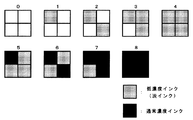
濃淡インクを用いて3値化するインクジェットプリンタにおいて、ハイライト部の粒状性を良好にするために淡インクの濃度を濃インクの1/4に希釈したものであれば3値の階調を0・64・255と階調値の間隔が不均等になり、特許文献1記載の式にて閾値を設定することができず、擬似輪郭が発生してしまう。同様に、淡インクの濃度を濃インクの1/4に希釈してあり9値誤差拡散して図3のような9インデックスパターンを用いる場合も9値の階調値の間隔は不均等になってしまう。さらに射出するインク量を制御することによりドット径を変化させることで多値化する場合、ドット径から階調値を求められる。この場合はインクの粘性、インク射出制御レベルから階調値の間隔が均等に割り当てられない場合がある。加えて、電子写真における出力の階調値はドットゲインや現像特性などにより階調値の間隔を均等にできない場合がある。
【0016】
このように階調の間隔が不均等である場合において出力装置の持つ階調近辺(量子化レベル)の濃度を出力する際に、擬似輪郭が発生するという問題が生じてきた。
【0017】
本発明は、かかる問題点に鑑みてなされたものであり、多値誤差拡散処理により出力装置の持つ階調近辺(量子化レベル)の濃度を出力する際に擬似輪郭が発生する問題を解決できる画像処理装置、画像記録装置及びプログラムを提供することを目的とする。
【0018】
特に請求項1、5、12記載の発明は、入力濃度値に対応して最適な量子化しきい値を設定することにより、量子化値近辺で発生する擬似輪郭を目立たなくさせ、良好な画質の出力画像結果を得ることを目的とする。
【0019】
また請求項2、6記載の発明は、最適な定数を設定することにより、量子化値近辺で発生する擬似輪郭を目立たなくすることができ、良好な画質の出力画像結果を得ることを目的とする。
【0020】
また請求項3、7記載の発明は、閾値を逐次処理で求めることで閾値を保持するLUTを必要とせず、省メモリ化することを目的とする。
【0021】
また請求項4、8記載の発明は、閾値をLUTで求めることで処理を高速化することを目的とする。
【0022】
また請求項9記載の発明は、同系色で濃度の異なるインクを用いることで3値以上の階調表現を可能とする装置において、量子化値近辺で発生する擬似輪郭を目立たなくさせ、良好な画質の出力画像結果を得ることを目的とする。
【0023】
また請求項10記載の発明は、濃度の異なるインクは、濃度の薄いインクは濃度の濃いインクを1/3以下に希釈したインクを用いることで3値以上の階調表現を可能とする装置において、量子化値近辺で発生する擬似輪郭を目立たなくさせ、良好な画質の出力画像結果を得ることを目的とする。
【0024】
また請求項11記載の発明は、吐出するインク量を制御することで3値以上の階調表現を可能とする装置において、量子化値近辺で発生する擬似輪郭を目立たなくさせ、良好な画質の出力画像結果を得ることを目的とする。
【0025】
【課題を解決するための手段】
上記課題を解決するため、本発明にかかる画像処理装置、画像記録装置及びプログラムでは、中間濃度に対する領域の感度を向上させ、その輪郭を明確にするために最適な閾値を設定してN値多値画像データを出力するものである。
【0026】
かかる目的を達成するために、請求項1記載の発明は、多値(M値)画像データを、不均等な階調の間隔で量子化を行う多値誤差拡散処理または不均等な階調の間隔で量子化を行う多値平均誤差最小法を用いてN値(M>N>2)に量子化し、N値の夫々に対応したドットを用いて記録を行う画像処理装置であって、注目画素の多値画像データに周辺の既に量子化済みの画素から拡散された誤差を加えた補正データを出力する手段と、注目画素の多値画像データに基づいて量子化閾値を設定する手段と、補正データと量子化閾値とを比較してN値画像データを出力する手段と、N値画像データの生成に伴って発生する誤差を算出する手段と、を備え、量子化値を1・2・…・a・b・…・Nとし、量子化値の階調をO1 ・O2 ・…・Oa ・Ob ・…・ON とするとき、入力値の区間Oa 〜Ob におけるi番目の閾値Thi(iは0<i≦N−1の整数)は、入力濃度値をInとしたとき、Thi=Ki ×In+(Oa +Ob )・(1−Ki )/2−(Oa −Oi ):(Ki は0以上の実数、iは0<i≦N−1の整数)、に基づき設定される値であることを特徴としている。
【0027】
請求項2記載の発明は、請求項1記載の発明において、Ki は、Ki ≦1であることを特徴としている。
【0028】
請求項3記載の発明は、請求項1記載の発明において、入力値に応じて逐次処理で前記閾値を求めることを特徴としている。
【0029】
請求項4記載の発明は、請求項1記載の発明において、入力値に応じてLUTより前記閾値を求めることを特徴としている。
【0030】
請求項5記載の発明は、多値(M値)画像データを、不均等な階調の間隔で量子化を行う多値誤差拡散処理または不均等な階調の間隔で量子化を行う多値平均誤差最小法を用いてN値(M>N>2)に量子化し、N値の夫々に対応したドットを用いて記録を行う画像記録装置であって、注目画素の多値画像データに周辺の既に量子化済みの画素から拡散された誤差を加えた補正データを出力する手段と、注目画素の多値画像データの入力濃度値に基づいて量子化閾値を設定する手段と、補正データと量子化閾値とを比較してN値画像データを出力する手段と、N値画像データの生成に伴って発生する誤差を算出する手段と、を備え、量子化値を1・2・…・a・b・…・Nとし、量子化値の階調をO1 ・O2 ・…・Oa ・Ob ・…・ON とするとき、入力値の区間Oa 〜Ob におけるi番目の閾値Thi(iは0<i≦N−1の整数)は、入力濃度値をInとしたとき、Thi=Ki ×In+(Oa +Ob )・(1−Ki )/2−(Oa −Oi ):(Ki は0以上の実数、iは0<i≦N−1の整数)、に基づき設定される値であることを特徴としている。
【0031】
請求項6記載の発明は、請求項5記載の発明において、Ki は、Ki ≦1であることを特徴としている。
【0032】
請求項7記載の発明は、請求項5記載の発明において、入力値に応じて逐次処理で前記閾値を求めることを特徴としている。
【0033】
請求項8記載の発明は、請求項5記載の発明において、入力値に応じてLUTより前記閾値を求めることを特徴としている。
【0034】
請求項9記載の発明は、請求項5記載の発明において、同系色で濃度の異なるインクを用いることで3値以上の階調表現を行うことを特徴としている。
【0035】
請求項10記載の発明は、請求項9記載の発明において、濃度の異なるインクにおいて、濃度の薄いインクは濃度の濃いインクを1/3以下に希釈したインクであることを特徴としている。
【0036】
請求項11記載の発明は、請求項5記載の発明において、吐出するインク量を制御することで3値以上の階調表現を行うことを特徴としている。
【0037】
請求項12記載の発明は、多値(M値)画像データを、不均等な階調の間隔で量子化を行う多値誤差拡散処理または不均等な階調の間隔で量子化を行う多値平均誤差最小法を用いてN値(M>N>2)に量子化し、N値の夫々に対応したドットを用いて記録を行う画像記録装置の記録制御処理をコンピュータに実行させるプログラムであって、注目画素の多値画像データに周辺の既に量子化済みの画素から拡散された誤差を加えた補正データを出力する工程のコードと、注目画素の多値画像データの入力濃度値に基づいて量子化閾値を設定する工程のコードと、補正データと量子化閾値とを比較してN値画像データを出力する工程のコードと、N値画像データの生成に伴って発生する誤差を算出する工程のコードと、を備え、量子化値を1・2・…・a・b・…・Nとし、量子化値の階調をO1 ・O2 ・…・Oa ・Ob ・…・ON とするとき、入力値の区間Oa 〜Ob におけるi番目の閾値Thi(iは0<i≦N−1の整数)は、入力濃度値をInとしたとき、Thi=Ki ×In+(Oa +Ob )・(1−Ki )/2−(Oa −Oi ):(Ki は0以上の実数、iは0<i≦N−1の整数)、に基づき設定される値であることを特徴としている。
【0038】
【発明の実施の形態】
以下、本発明の好適な実施の形態を添付図面を参照しながら詳細に説明する。構成要素には記号を付与して区別する。図1は、本発明の実施の形態における画像処理装置のブロック構成を示す図である(特に本発明に特徴的な画像処理を行う画像処理部のブロック構成を示す)。また、図2は、本発明の実施の形態における画像記録装置の構成を示す図である。
【0039】
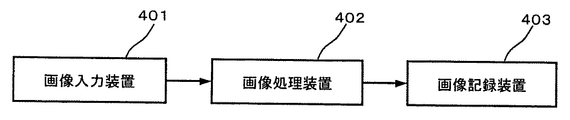
図4は、本発明の実施の形態の画像処理装置を用いて構成される画像入出力システムの構成を示す。画像入力装置401はスキャナやディジタルカメラ等の入力デバイスを示し、入力画像について例えば8ビット精度ならば256階調の画像データとして取り込まれる。この多値画像データが本実施形態の画像処理装置402に入力される。
【0040】
画像処理装置(画像処理部)402では、画像入力装置401から入力された256階調の画像データに対し、この後段の画像出力装置403で出力可能な階調数に変換する処理を行う。この階調数変換処理では多値誤差拡散処理を用いてもよい。画像出力装置403が、図3に示すように1ドット単位で3階調表現ができるとすると、3値の誤差拡散処理を行うことになる。ここで、図3の”0”,”1”,”2”は、画像処理装置402で3値化した後の情報を表し、この画像データが図2に構成を示すような画像記録装置(画像形成装置、画像出力装置)403に送られる。
【0041】
図2において、画像出力装置403は、フレーム1に横架したガイドレール2,3に移動可能に載設されたキャリッジにインクジェット記録ヘッド5(以下、単に「記録ヘッド」と称す)を搭載し、図示しないモータ等の駆動源によってキャリッジをガイドレール方向に移動して走査(主走査)可能とするとともに、ガイド板6にセットされる用紙7を、図示しない駆動源によってドライブギヤ8及びスプロケットギヤ9を介して回動される送りノブ10aを備えたプラテン10にて取込み、プラテン10周面とこれに圧接するプレッシャローラ11とによって搬送し、記録ヘッド5によって用紙7に印字記録する。
【0042】
記録ヘッド5は、図5に示すブラック(K)、イエロー(Y)、マゼンタ(M)及びシアン(C)の各インクをそれぞれ吐出するための4個のインクジェットヘッド{5K、5Y、5M、5C}や、図6に示すブラック(K)、イエロー(Y)、マゼンタ(M)、シアン(C)、ライトイエロー(LY)、ライトマゼンタ(LM)及びライトシアン(LC)の各インクをそれぞれ吐出するための7個のインクジェットヘッド{5K、5Y、5M、5C、5LY、5LM、5LM}を主走査方向の同一線上に配置して構成している。商品構成によってはインクの数を増減させても何ら構わない。具体的にはハイライト部でイエローのドットは目視し難い特性を持つのでライトイエローを省いてコストダウンを行った構成としても良いし、また、ライトブラックや、シアン・マゼンタ・イエロー・ブラックの各色の濃度を3段・4段に分けた構成にして高画質を実現した記録ヘッドとしてもよい。
【0043】
上記の各インクジェットヘッドは、例えば圧電素子、気泡発生用ヒータ等のエネルギー発生手段であるアクチュエータを選択的に駆動して、液室内のインクに圧力を与えることによって、この液室に連通するノズルからインク滴を吐出飛翔させて、用紙7に付着させることで画像記録(画像形成)する。ここでアクチュエータの駆動信号を多数用意することにより1ノズルから吐出されるインク量を制御することが可能となり、用紙上で大小ドット、大中小ドットなど多階調表現が可能となる。
【0044】
画像記録装置403は、図3に示すように出力の対象となっているドットの制御を行う。”0”はドットを打たないことを示し(以下、「ドットoff」)、”2”は通常のインク濃度(以下、「通常インク」)によるドットを打つことを示し、”1”は2における通常インクを希釈した淡い濃度インク(以下、「淡インク」)のドットを打つことを示す。ここでは、図3に示すように画像出力装置が濃度変調できる場合を示したが、本発明が適用される範囲はこれに限定されるものではない。例えば、図14、15に示すように2値のドットを複数個集めて多値の階調を表現する場合、射出するインク量を制御することにより多値の階調を表現する場合、書込みの露光をパルス幅分割して1ドットの露光量を制御させることにより多値の階調を表現する場合、露光で用いるレーザー光の強度に強弱を加えることにより多値の階調を表現する場合等でも本発明にかかる処理方法が適用可能である。
【0045】
また、図4のシステム構成図では、処理に応じてそれぞれの装置を独立したものとして示したが、この限りではなく、画像処理装置402の機能が画像入力装置401中に存在する形態や、画像出力装置403中に存在する形態等もある。
【0046】
図1は、図4に示す本実施形態の画像処理装置402の構成を示すブロック図である。入力端子906からは画像入力装置401より多値画像データが入力される。ここで、2次元の画像データを表わすために、In(x,y)として表わす(xは画像の主走査方向のアドレス、yは副走査方向のアドレスを示す)。
【0047】
次に、このIn(x,y)が加算器903に入力される。加算器903には、誤差メモリ904に格納されている、現画素以前の誤差拡散処理により拡散・蓄積されてきた誤差のうち、現画素に割り当てられた誤差成分E(x,y)が入力され、In(x,y)と加算され、その結果が出力される。この出力信号を補正データC(x,y)とする。
【0048】
また、入力データIn(x,y)は閾値設定部901に入力され、本発明にかかわる多値誤差拡散処理に用いる閾値Th(x,y)の設定を行う。ここで閾値は以下のような式に則って設定される。説明を単純化するため、ここでは出力装置403の出力可能な階調数が3値の場合で説明する(もちろんこの階調数以外にも同様に適用することが可能である)。淡インクは通常インクを1/4に希釈したものを用いた場合における、図3のドットoff・淡インクドット・通常インクドットの階調値は0・64・255として説明する。
【0049】

【0050】
式(1)〜(4)に基づき設定される閾値をもとに3値量子化が図1に示す画像処理部にて実行される。
【0051】
閾値設定部901は入力データIn(x,y)が0≦In(x,y)≦64であれば、式(1)と入力データIn(x,y)で設定された閾値Th1(x,y)、式(2)と入力データIn(x,y)で設定された閾値Th2(x,y)を比較判定部902へ出力する。入力データIn(x,y)が65≦In(x,y)≦255であれば、式(3)と入力データIn(x,y)で設定された閾値Th1(x,y)、式(4)と入力データIn(x,y)で設定された閾値Th2(x,y)を比較判定部902へ出力する。
【0052】
比較判定部902は、入力データIn(x,y)に誤差E(x,y)が加算された補正データC(x,y)と、閾値設定部901で設定された閾値Th1(x,y)及び閾値Th2(x,y)に基づいて下記のように出力する濃度値Out(x,y)を決定する。
【0053】
このOut(x,y)が出力端子907から画像出力装置403に対して出力される。
【0055】
また、出力値Out(x,y)は減算器905に入力され、補正データC(x,y)から減算されて、現画素で発生した誤差e(x,y)が算出される。
【0056】
次に誤差拡散部908では予め設定された拡散係数に基づいて、誤差e(x,y)を配分して誤差メモリ904に蓄積されている誤差データE(x,y)に加算していく。ここで例えば拡散係数として図7に示したような係数を用いた場合、誤差拡散部908では下記のような処理を行う。
【0057】
E(x,y+1) =E(x,y+1) +e(x,y)×7/16・・・(8)
E(x+1,y−1)=E(x+1,y−1)+e(x,y)×3/16・・・(9)
E(x+1,y) =E(x+1,y) +e(x,y)×5/16・・・(10)
E(x+1,y+1)=E(x+1,y+1)+e(x,y)×1/16・・・(11)
【0058】
この誤差拡散処理で発生した誤差データは誤差メモリ904に格納される。
【0059】
以上のように図1の構成によって、画像処理部における多値誤差拡散処理が行われる。
【0060】
次に、このような処理によりなぜ擬似輪郭が低減されるかについて説明する。図8は、入力画像が0から255のグラデーションの時に、従来の方法による3値(0,64,255)の誤差拡散処理を施した結果を示したもので(※グラデーションは疑似的に示した)、64の濃度近辺で、64のドットのみで形成される領域が発生する。この部分が擬似輪郭として知覚される。
【0061】
この原因としては、各階調ごとの粒状度をグラフに表してみるとわかりやすい。今、0から255までの濃度のパッチ(ただし各濃度値を十分表現できるのに十分な面積を持つ)を3値誤差拡散処理で示すと図9のように64濃度近辺の粒状度が急激に少なくなっている。これは入力濃度値が64に近い値だったときには或る領域で見たときの64によるドットの占める割合が非常に高く、粒状度の値としては小さくなる。それに対して入力濃度値が32や192であったときには、ほとんど2画素に1回の割合で2種類の濃度のドットが交互に発生する形になるため、粒状度の値としては非常に高くなっている。
【0062】
ただしこれらの0から255の256個のパッチのまま並べてみても擬似輪郭としては見えにくいが、これを幅の小さいグラデーションとして出力すると、それぞれの入力濃度値に相当する微視的な領域の粒状度は図10のようになり、濃度64を中心としてかなりの幅で粒状度の値がほぼ0となる。すなわちその領域では64のドットしか発生していない。これは各濃度領域におけるドット発生に対する感度の違いが出ているものである。先ほど述べたように、0,64,255の3値のドットを用いる場合、濃度32を表現するためには、平均的に見て0と64のドットが1ドットずつ、計2ドット存在すればよい。これに対して濃度63を表現しようとすれば、平均的に見ると、0のドットが1ドットと64のドットが63ドット、計64ドット存在しなければならない。そこで今出力しようとしているグラデーションの幅が各濃度値に対して例えば1ドットしかないような場合には、中間濃度64近辺の濃度は平均的に見ればほとんど64の濃度で表現されてしまい、グラデーションの幅に比較して、大きな幅の均一パターンとなるため、その均一パターンと、それ以外の領域との境界が擬似輪郭として見えている。
【0063】
この現象は多値誤差拡散だけではなく、多値ディザでも起こる。ただし多値ディザとの差はこの均一パターンの幅の広さにある。同一のグラデーションの幅を3値の誤差拡散処理とディザ処理を行ったときの出力結果を見ると、明らかに誤差拡散処理の方が均一パターンの領域の幅が広い。これは誤差拡散処理特有のはき寄せ現象によるものである。64の入力濃度から255に向かうグラデーションにおいて255のドット発生を行うためには、正の誤差が蓄積されていく必要がある。しかし64に非常に近い領域では誤差の絶対値も小さく、255のドット出力を行う閾値160を超えるまでには94以上の誤差が蓄積されなければならない。これに対して多値のディザについては、そのディザの閾値マトリクスと画素位置によってドットが発生する/しないが決まり、画像中のある画素位置によっては、入力濃度値が65であっても、255のドット発生が行われる可能性はある。よって多値ディザに比較して、多値誤差拡散は出力濃度値近辺ではドット発生が遅れる傾向にあり、そのために中間濃度部での均一パターンの幅も広くなってしまう。
【0064】
この問題点を解決するために、本発明では式(1)、(4)のように入力濃度値に応じて閾値の変更を行う。こうすることで、均一パターンの幅を小さくすることができる。これは出力濃度値近辺でのドット発生に対する感度を上げることが目的である。例えば式(1)、(4)のKの値が0.5であるとし、入力濃度値が65の場合、従来の固定化された閾値では255のドット発生のためには誤差加算後の補正データの値が160よりも大きくなければならなかったが、本実施形態の式(1)、(4)によれば、112.5となる。従って処理画素が進んで誤差の蓄積が112.5−65=47.5を超えた時点で255のドット発生が行われる。すなわち誤差拡散処理特有のはき寄せ現象による均一パターンの幅の広さを狭くすることができ、擬似輪郭として目立ちにくくなる。
【0065】
ここで、式(1)、(4)の中の定数Kについては、これらを調整することで、均一パターンの幅を制御することが可能である。この定数を変化させたときの閾値の特性をグラフに示したものを図11に示す。図11でK1,K2の値が0の時とは、従来の固定閾値の場合である。K1,K2を0.25・0.5・1と変化させていくと直線の傾きが増していく。そして、中間濃度値64近辺での2つの閾値の差が縮まってくる。これはこの近辺で、0や255の濃度のドットが発生しやすくなっていることを示す。ただしこの定数の値をあまり大きくすると逆に悪影響が発生してしまう。グラデーションを出力するとその出力濃度値近辺にドットが並びそれが線となって見えてしまう現象が発生する。従ってこれら定数の値は実験によりK≦1で擬似輪郭として目立ちにくく、かつ悪影響を起こさない最適な値となる。もちろんこれは画像によって多少異なる値を用いた方が良好な結果をもたらす場合もあり得るため、各画像にて最適な処理を施したい場合には、それぞれの画像によって所望の値を用いれば良い。
【0066】
本発明の他の実施形態として、図11では2つの定数に同じ値を用いていたが、異なる値を用いることでさらに最適な閾値特性を選択することが可能である。実際の出力装置においては、ドットゲイン等が存在し、同じドットを打つ場合でも、出力媒体上にドットをまばらに打つ低濃度部と、ドットを密に打つ高濃度部では明らかに特性が異なる。従ってそれぞれの濃度に応じた最適な定数を別個に選択すれば良い。
【0067】
また、式(1)〜(4)では入力濃度による1次関数で定義されていたが、本発明はこれに限るものではなく、必要に応じて高次の関数を用いて、閾値の特性を非線型にとることも可能である。また、図12に示すように中間濃度部近辺のみ閾値を濃度によって変えても良い。0や255の濃度においては誤差拡散のはき寄せ現象は同様に発生するが、擬似輪郭としては知覚されない。従って擬似輪郭解決のためだけであれば、中間濃度のみの対策を行うことでも十分である。
【0068】
また、上記実施形態では式(1)〜(4)と入力値から逐次処理により閾値Th1(x,y)・閾値Th2(x,y)を求めたが、入力値256階調に対して閾値Th1・Th2を事前に計算しておき、計算結果をLUT(LookUp Table)に保持してこれを使用することにより高速化する形態としても構わない。
【0069】
また、本発明は多値誤差拡散処理に対するものであったが、同じように多値平均誤差最小法にも適用できる。
【0070】
なお、本発明は、複数の機器(例えばホストコンピュータ,インタフェース機器,リーダ,プリンタなど)から構成されるシステムに適用しても、一つの機器からなる装置(例えば、複写機,ファクシミリ装置など)に適用してもよい。
【0071】
また、本発明の目的は、前述した実施形態の機能を実現するソフトウェアのプログラムコードを記録した記憶媒体を、システムあるいは装置に供給し、そのシステムあるいは装置のコンピュータ(CPUやMPU)が記憶媒体に格納されたプログラムコードを読出し実行することによっても、達成されることは言うまでもない。この場合、記憶媒体から読出されたプログラムコード自体が前述した実施形態の機能を実現することになる。
【0072】
プログラムコードを供給するための記憶媒体としては、例えば、フレキシブルディスク,ハードディスク,光ディスク,光磁気ディスク,磁気テープ,不揮発性のメモリカード,ROMなどを用いることができる。
【0073】
また、コンピュータが読出したプログラムコードを実行することにより、前述した実施形態の機能が実現されるだけでなく、そのプログラムコードの指示に基づき、コンピュータ上で稼働しているOS(オペレーティングシステム)などが実際の処理の一部または全部を行い、その処理によって前述した実施形態の機能が実現される場合も含まれることは言うまでもない。
【0074】
さらに、記憶媒体から読出されたプログラムコードが、コンピュータに挿入された機能拡張ボードやコンピュータに接続された機能拡張ユニットに備わるメモリに書込まれた後、そのプログラムコードの指示に基づき、その機能拡張ボードや機能拡張ユニットに備わるCPUなどが実際の処理の一部または全部を行い、その処理によって前述した実施形態の機能が実現される場合も含まれることは言うまでもない。
【0075】
以上により本発明の実施の形態について説明した。なお、上述した実施形態は、本発明の好適な実施形態の一例を示すものであり、本発明はそれに限定されるものではなく、その要旨を逸脱しない範囲内において、種々変形実施が可能である。
【0076】
【発明の効果】
以上の説明から明らかなように、本発明によれば、入力濃度値に対応して最適な量子化閾値を設定することにより、多値誤差拡散法により発生する量子化レベル付近の擬似輪郭を最小限に抑えることができ、画質への悪影響を解消することができる。
【0077】
請求項1、5、12記載の発明では、入力濃度値に対応して最適な量子化しきい値を設定することにより、量子化値近辺で発生する擬似輪郭を目立たなくすることができ、良好な画質の出力画像結果を得ることができ、画質への悪影響を解消する。
【0078】
請求項2、6記載の発明では、最適な定数を設定することにより、量子化値近辺で発生する擬似輪郭を目立たなくすることができ、良好な画質の出力画像結果を得ることができ、画質への悪影響を解消する。
【0079】
請求項3、7記載の発明では、閾値を逐次処理で求めることで閾値を保持するLUTを必要とせず、省メモリとすることができる。
【0080】
請求項4、8記載の発明では、閾値をLUTで求めることで、処理を高速化することができる。
【0081】
請求項9記載の発明では、同系色で濃度の異なるインクを用いることで3値以上の階調表現を可能とする装置において、量子化値近辺で発生する擬似輪郭を目立たなくすることができ、良好な画質の出力画像結果を得ることができ、画質への悪影響を解消する。
【0082】
請求項10記載の発明では、濃度の異なるインクは、濃度の薄いインクは濃度の濃いインクを1/3以下に希釈したインクを用いることで3値以上の階調表現を可能とする装置において、量子化値近辺で発生する擬似輪郭を目立たなくすることができ、良好な画質の出力画像結果を得ることができ、画質への悪影響を解消する。
【0083】
請求項11記載の発明では、吐出するインク量を制御することで3値以上の階調表現を可能とする装置において、量子化値近辺で発生する擬似輪郭を目立たなくすることができ、良好な画質の出力画像結果を得ることができ、画質への悪影響を解消する。
【図面の簡単な説明】
【図1】本発明の実施の形態における画像処理装置の画像処理部のブロック構成を示す図である。
【図2】本発明の実施の形態における画像記録装置の構成を示す図である。
【図3】画像記録装置における、ドットoff・淡インク・通常濃度インクの3階調の濃度変調を行う場合の出力ドットを示す図である。
【図4】本発明の実施の形態における画像処理装置及び画像記録装置を含んで構成される画像入出力システムの構成を示す図である。
【図5】インクジェットヘッド(4色)の構成を示す図である。
【図6】インクジェットヘッド(7色)の構成を示す図である。
【図7】拡散係数の例を示す図である。
【図8】入力画像が0から255のグラデーションの場合における、3値(0,64,255)の誤差拡散処理を施した結果を示した図である。
【図9】入力値の階調ごとの粒状度を示すグラフである。
【図10】入力濃度値に相当する微視的な領域の粒状度を示すグラフである。
【図11】定数Kを変化させたときの閾値の特性を示すグラフである。
【図12】中間濃度部近辺のみ閾値を濃度によって変える場合の閾値特性を示すグラフである。
【図13】ホストから出力装置への多値画像データの処理の流れについて示す図である。
【図14】インデックスパターンの例(その1)について示す図である。
【図15】インデックスパターンの例(その2)について示す図である。
【符号の説明】
401 画像入力装置
402 画像処理装置
403 画像記録装置
1 フレーム
2、3 ガイドレール
5 記録ヘッド
6 ガイド板
7 用紙
8 ドライブギヤ
9 スプロケットギヤ
10 プラテン
10a 送りノブ
11 プレッシャローラ
5Y、5M、5C、5K、5LY、5LM、5LC インクジェットヘッド
901 閾値設定部
902 比較判定部
903 加算器
904 誤差メモリ
905 減算器
906 入力
907 出力
908 誤差拡散部
In(x,y) 入力データ
Out(x,y) 出力データ
C(x,y) 補正データ
Th1(x,y),Th2(x,y) 閾値
e(x,y) 誤差
E(x,y) 誤差成分データ
K1,K2 定数
101 アプリケーション
102 制御部
103 色処理部
104 5値化処理部
105 圧縮処理部
106 インタフェース
107 出力装置
108 展開部
109 記録ヘッド[0001]
BACKGROUND OF THE INVENTION
The present invention relates to an image processing apparatus, an image recording apparatus (image forming apparatus), and a program for printing multivalued image data with high definition and high gradation.
[0002]
[Prior art]
There is an image input / output system that outputs multi-valued image data read by an input device such as a scanner or a digital camera to an output device such as a printer or a display. At that time, multi-valued image data read by the input device (for example, 256 gradations for 8-bit accuracy) is converted into image data of the number of gradations that can be output by the output device, and pseudo continuous gradation is expressed. There is a method called pseudo halftone processing.
[0003]
In particular, binarization processing is conventionally performed when the output device can express only binary values of ON / OFF of dots. Among these binarization processes, there are an error diffusion process and an average error minimum method that are excellent in both resolution and gradation. The error diffusion method and the minimum average error method are logically equivalent, only differing when the error diffusion operation is performed.
[0004]
Furthermore, there is a multi-value error diffusion process in which this error diffusion process is applied not only to binary but also to the number of gradations of 3 or more. Similar to the binary error diffusion process, it is possible to perform a process with excellent gradation and resolution.
[0005]
There are various methods for securing the number of gradations of three or more values in the output device. Inkjet printers are ternarized by controlling the amount of ink to be ejected to change the dot diameter, such as small, medium, and large dots, a method of overprinting dots, and a method that uses inks with different densities and light / dark inks. The above gradation numbers are reproduced. In general, the density of the light ink is diluted to 1/2 to 1/6 of the dark ink. In electrophotography, the exposure of writing is divided into pulse widths to control the exposure amount to form one dot, and the dot diameter is modulated by adding strength to the intensity of laser light used for exposure. Yes.
[0006]
In addition, in a high-resolution binary output device, such as a recent image recording device using an inkjet method, a multi-value error diffusion method (“index method”) is used to process a smoother halftone image at high speed. Is being used. An example of the index method will be described taking an ink jet recording apparatus having a resolution of 600 × 600 dpi as an example.
[0007]
FIG. 13 is a diagram showing a flow of processing of the error diffusion method expressed in multiple gradations. As shown in the figure, the multi-value data output from the
[0008]
In an ink jet recording apparatus using dark and light inks, high-quality output of 9 gradations with less noticeable graininess can be realized by using a 9-value index method as shown in FIG.
[0009]
One problem with multi-level error diffusion processing with excellent gradation is that a pseudo contour is generated when the density near the gradation (quantization level) of the output device is output.
[0010]
The reason why the pseudo contour is generated is that a texture change is conspicuous because a dither pattern does not occur when the original image signal is near the quantization level.
[0011]
As a means for solving such a problem of pseudo contour generation, there is a method of making the pseudo contour inconspicuous by superimposing noise such as random noise. As a method of superimposing noise, there are a method of adding an input image to the original data and a method of randomly distributing the threshold value itself used for error diffusion processing. By superimposing this noise, the pseudo contour itself can be made almost inconspicuous, but the problem arises that the contour portion of the image becomes unclear.
[0012]
As a technique for solving the above problem, for example, there is a technique described in
[0013]
[Patent Document 1]
JP 2000-270210 A
[0014]
[Problems to be solved by the invention]
The technique described in the above-mentioned
[0015]
In an ink jet printer that uses ternary ink using dark and light inks, if the density of the light ink is diluted to ¼ that of dark ink in order to improve the granularity of the highlight area, the ternary gradation is set to 0. The intervals between the gradation values of 64 and 255 are not uniform, the threshold value cannot be set by the expression described in
[0016]
As described above, there is a problem that a pseudo contour is generated when the density in the vicinity of the gradation (quantization level) of the output device is output when the intervals of the gradation are uneven.
[0017]
The present invention has been made in view of such a problem, and can solve the problem that a pseudo contour is generated when a density near a gradation (quantization level) of an output device is output by multi-value error diffusion processing. An object is to provide an image processing apparatus, an image recording apparatus, and a program.
[0018]
In particular, the invention described in
[0019]
The inventions of
[0020]
Further, the present invention has an object of saving memory without requiring an LUT for holding a threshold value by obtaining the threshold value by sequential processing.
[0021]
The inventions of
[0022]
According to the ninth aspect of the present invention, in an apparatus that enables gradation expression of three or more values by using inks of similar colors and different densities, the pseudo contour generated in the vicinity of the quantized value is made inconspicuous. The purpose is to obtain an output image result of image quality.
[0023]
According to a tenth aspect of the present invention, there is provided an apparatus capable of expressing gradations of three or more values by using inks having different densities, inks obtained by diluting light inks having a low density to 1/3 or less. An object of the present invention is to obtain an output image result with good image quality by making the pseudo contour generated near the quantized value inconspicuous.
[0024]
According to the eleventh aspect of the present invention, in an apparatus that enables gradation expression of three or more values by controlling the amount of ink to be ejected, the pseudo contour generated in the vicinity of the quantized value is made inconspicuous, and good image quality is achieved. The purpose is to obtain an output image result.
[0025]
[Means for Solving the Problems]
In order to solve the above problems, in the image processing apparatus, the image recording apparatus, and the program according to the present invention, an optimum threshold value is set in order to improve the sensitivity of the area with respect to the intermediate density and to clarify the outline, thereby increasing the N value. Value image data is output.
[0026]
In order to achieve such an object, the invention according to
[0027]
The invention described in
[0028]
The invention described in
[0029]
A fourth aspect of the invention is characterized in that, in the first aspect of the invention, the threshold value is obtained from an LUT according to an input value.
[0030]
In the invention according to
[0031]
The invention described in
[0032]
The invention described in
[0033]
The invention described in
[0034]
The invention described in
[0035]
A tenth aspect of the invention is characterized in that, in the ninth aspect of the invention, in the ink having different densities, the low density ink is an ink obtained by diluting the high density ink to 1/3 or less.
[0036]
The invention described in
[0037]
The invention according to claim 12 is the multi-value (M-value) image data, Quantize at uneven gradation intervals Multilevel error diffusion processing or Quantize at uneven gradation intervals A program that causes a computer to execute a recording control process of an image recording apparatus that performs quantization using N dots (M>N> 2) using a multi-value average error minimum method and performs recording using dots corresponding to each of the N values. Based on the multi-valued image data of the target pixel and correction data that is output by adding an error diffused from surrounding already quantized pixels and the input density value of the multi-valued image data of the target pixel The code for the step of setting the quantization threshold, the code for the step of outputting the N-value image data by comparing the correction data and the quantization threshold, and the error generated when the N-value image data is generated are calculated. .., N, and the gradation of the quantized value is O1, O2,... Oa, Ob,. , The i-th threshold Thi in the interval Oa to Ob of the input value i is an integer of 0 <i ≦ N−1), where T i = K i × In + (O a + O b) · (1−K i) / 2− (O a −O i): (K i is A real number greater than or equal to 0, i is a value set based on 0 <i ≦ N−1).
[0038]
DETAILED DESCRIPTION OF THE INVENTION
DESCRIPTION OF EXEMPLARY EMBODIMENTS Hereinafter, preferred embodiments of the invention will be described in detail with reference to the accompanying drawings. Components are distinguished by adding symbols. FIG. 1 is a diagram showing a block configuration of an image processing apparatus according to an embodiment of the present invention (in particular, a block configuration of an image processing unit that performs image processing characteristic of the present invention). FIG. 2 is a diagram showing the configuration of the image recording apparatus according to the embodiment of the present invention.
[0039]
FIG. 4 shows a configuration of an image input / output system configured using the image processing apparatus according to the embodiment of the present invention. An
[0040]
The image processing apparatus (image processing unit) 402 performs processing for converting the 256 gradation image data input from the
[0041]
In FIG. 2, an
[0042]
The
[0043]
Each of the above-described ink jet heads selectively drives an actuator, which is an energy generating means such as a piezoelectric element or a bubble generating heater, to apply pressure to the ink in the liquid chamber, and thereby from the nozzle communicating with the liquid chamber. An image is recorded (image formation) by ejecting ink droplets and making them adhere to the
[0044]
As shown in FIG. 3, the
[0045]
Further, in the system configuration diagram of FIG. 4, each device is illustrated as being independent according to processing, but this is not restrictive, and the form in which the function of the
[0046]
FIG. 1 is a block diagram showing the configuration of the
[0047]
Next, this In (x, y) is input to the
[0048]
The input data In (x, y) is input to the threshold
[0049]
[0050]
Based on the threshold value set based on the equations (1) to (4), ternary quantization is executed by the image processing unit shown in FIG.
[0051]
If the input data In (x, y) is 0 ≦ In (x, y) ≦ 64, the threshold
[0052]
The
[0053]
This Out (x, y) is output from the
[0055]
The output value Out (x, y) is input to the
[0056]
Next, the
[0057]
E (x, y + 1) = E (x, y + 1) + e (x, y) × 7/16 (8)
E (x + 1, y−1) = E (x + 1, y−1) + e (x, y) × 3/16 (9)
E (x + 1, y) = E (x + 1, y) + e (x, y) × 5/16 (10)
E (x + 1, y + 1) = E (x + 1, y + 1) + e (x, y) × 1/16 (11)
[0058]
Error data generated by the error diffusion process is stored in the
[0059]
As described above, the multi-value error diffusion processing in the image processing unit is performed by the configuration of FIG.
[0060]
Next, the reason why the pseudo contour is reduced by such processing will be described. FIG. 8 shows the result of error diffusion processing of three values (0, 64, 255) according to the conventional method when the input image has a gradation of 0 to 255 (* gradation is shown in a pseudo manner) ), An area formed by only 64 dots is generated in the vicinity of 64 density. This part is perceived as a pseudo contour.
[0061]
This can be easily understood by expressing the granularity for each gradation on a graph. Now, if a patch having a density from 0 to 255 (however, having an area sufficient to express each density value) is represented by ternary error diffusion processing, the granularity around 64 density is rapidly increased as shown in FIG. It is running low. When the input density value is close to 64, the proportion of dots occupied by 64 when viewed in a certain area is very high, and the granularity value becomes small. On the other hand, when the input density value is 32 or 192, since dots of two types of density are generated alternately at a rate of about once every two pixels, the granularity value is very high. ing.
[0062]
However, even if these 256 patches from 0 to 255 are arranged as they are, they are difficult to see as a pseudo contour, but if this is output as a gradation with a small width, the granularity of the microscopic area corresponding to each input density value Is as shown in FIG. 10, and the value of the granularity is substantially 0 with a considerable width around the
[0063]
This phenomenon occurs not only with multilevel error diffusion but also with multilevel dither. However, the difference from the multi-value dither is in the width of the uniform pattern. Looking at the output results when ternary error diffusion processing and dither processing are performed for the same gradation width, the error diffusion processing clearly has a wider uniform pattern area. This is due to the rush phenomenon peculiar to error diffusion processing. In order to generate 255 dots in a gradation from 64 input density to 255, it is necessary to accumulate positive errors. However, in an area very close to 64, the absolute value of the error is small, and an error of 94 or more must be accumulated before the
[0064]
In order to solve this problem, in the present invention, the threshold value is changed according to the input density value as shown in equations (1) and (4). By doing so, the width of the uniform pattern can be reduced. The purpose of this is to increase the sensitivity to dot generation near the output density value. For example, if the value of K in equations (1) and (4) is 0.5 and the input density value is 65, the correction after error addition is necessary to generate 255 dots with the conventional fixed threshold value. Although the value of the data had to be larger than 160, according to the equations (1) and (4) of this embodiment, it is 112.5. Therefore, 255 dots are generated when the processing pixel advances and the error accumulation exceeds 112.5−65 = 47.5. In other words, the width of the uniform pattern due to the gathering phenomenon peculiar to the error diffusion process can be narrowed, and the pseudo contour becomes less conspicuous.
[0065]
Here, with respect to the constant K in the expressions (1) and (4), it is possible to control the width of the uniform pattern by adjusting these constants. FIG. 11 shows a graph of threshold characteristics when this constant is changed. In FIG. 11, the case where the values of K1 and K2 are 0 is the case of the conventional fixed threshold value. As K1 and K2 are changed to 0.25 · 0.5 · 1, the slope of the straight line increases. Then, the difference between the two threshold values near the
[0066]
As another embodiment of the present invention, the same value is used for two constants in FIG. 11, but it is possible to select a more optimal threshold characteristic by using different values. In an actual output device, there is a dot gain or the like, and even when hitting the same dot, the characteristic is clearly different between a low density portion where dots are sparsely hit on the output medium and a high density portion where dots are hit densely. Therefore, an optimal constant corresponding to each concentration may be separately selected.
[0067]
In addition, in the equations (1) to (4), the linear function is defined by the input density. However, the present invention is not limited to this, and the threshold characteristic is set using a higher-order function as necessary. It can also be non-linear. Further, as shown in FIG. 12, the threshold value may be changed depending on the density only in the vicinity of the intermediate density portion. At a density of 0 or 255, the error diffusion threshold phenomenon occurs in the same manner, but is not perceived as a pseudo contour. Therefore, if it is only for solving the pseudo contour, it is sufficient to take measures only for the intermediate density.
[0068]
In the above embodiment, the threshold value Th1 (x, y) and the threshold value Th2 (x, y) are obtained by sequential processing from the expressions (1) to (4) and the input value. Th1 and Th2 may be calculated in advance, and the calculation result may be stored in an LUT (LookUp Table) and used to increase the speed.
[0069]
Although the present invention is for multi-level error diffusion processing, it can be similarly applied to the multi-level average error minimum method.
[0070]
Note that the present invention can be applied to a system including a plurality of devices (for example, a host computer, an interface device, a reader, a printer, etc.), or an apparatus including a single device (for example, a copier, a facsimile machine, etc.). You may apply.
[0071]
Another object of the present invention is to supply a storage medium storing software program codes for realizing the functions of the above-described embodiments to a system or apparatus, and the computer (CPU or MPU) of the system or apparatus stores the storage medium. Needless to say, this can also be achieved by reading and executing the stored program code. In this case, the program code itself read from the storage medium realizes the functions of the above-described embodiment.
[0072]
As a storage medium for supplying the program code, for example, a flexible disk, a hard disk, an optical disk, a magneto-optical disk, a magnetic tape, a nonvolatile memory card, a ROM, or the like can be used.
[0073]
Further, by executing the program code read by the computer, not only the functions of the above-described embodiments are realized, but also an OS (operating system) operating on the computer based on the instruction of the program code. It goes without saying that a case where the function of the above-described embodiment is realized by performing part or all of the actual processing and the processing is included.
[0074]
Further, after the program code read from the storage medium is written into a memory provided in a function expansion board inserted into the computer or a function expansion unit connected to the computer, the function expansion is performed based on the instruction of the program code. It goes without saying that the CPU or the like provided in the board or the function expansion unit performs part or all of the actual processing, and the functions of the above-described embodiments are realized by the processing.
[0075]
The embodiment of the present invention has been described above. The above-described embodiment shows an example of a preferred embodiment of the present invention, and the present invention is not limited thereto, and various modifications can be made without departing from the scope of the invention. .
[0076]
【The invention's effect】
As is clear from the above description, according to the present invention, the pseudo contour near the quantization level generated by the multi-level error diffusion method is minimized by setting an optimal quantization threshold corresponding to the input density value. The adverse effect on image quality can be eliminated.
[0077]
According to the first, fifth, and twelfth aspects of the invention, by setting an optimal quantization threshold corresponding to the input density value, the pseudo contour generated near the quantization value can be made inconspicuous, An output image result of image quality can be obtained, and adverse effects on image quality are eliminated.
[0078]
According to the second and sixth aspects of the invention, by setting an optimal constant, it is possible to make the pseudo contour generated in the vicinity of the quantized value inconspicuous, and to obtain an output image result with good image quality. Eliminate adverse effects on
[0079]
According to the third and seventh aspects of the present invention, it is possible to save memory without requiring an LUT for holding the threshold value by obtaining the threshold value by sequential processing.
[0080]
In the inventions according to
[0081]
In the invention according to
[0082]
According to a tenth aspect of the present invention, there is provided an apparatus capable of expressing gradations of three or more values by using ink obtained by diluting a low density ink to 1/3 or less of a low density ink for an ink having a different density. The pseudo contour generated in the vicinity of the quantized value can be made inconspicuous, an output image result with good image quality can be obtained, and adverse effects on the image quality can be eliminated.
[0083]
According to the invention of
[Brief description of the drawings]
FIG. 1 is a diagram illustrating a block configuration of an image processing unit of an image processing apparatus according to an embodiment of the present invention.
FIG. 2 is a diagram illustrating a configuration of an image recording apparatus according to an embodiment of the present invention.
FIG. 3 is a diagram showing output dots when performing three-tone density modulation of dot off, light ink, and normal density ink in the image recording apparatus.
FIG. 4 is a diagram illustrating a configuration of an image input / output system including an image processing apparatus and an image recording apparatus according to an embodiment of the present invention.
FIG. 5 is a diagram illustrating a configuration of an inkjet head (4 colors).
FIG. 6 is a diagram illustrating a configuration of an inkjet head (7 colors).
FIG. 7 is a diagram illustrating an example of a diffusion coefficient.
FIG. 8 is a diagram illustrating a result of ternary (0, 64, 255) error diffusion processing when an input image has a gradation of 0 to 255;
FIG. 9 is a graph showing granularity for each gradation of input values.
FIG. 10 is a graph showing the granularity of a microscopic region corresponding to an input density value.
FIG. 11 is a graph showing threshold characteristics when the constant K is changed.
FIG. 12 is a graph showing threshold characteristics when the threshold is changed depending on the density only in the vicinity of the intermediate density portion.
FIG. 13 is a diagram illustrating a flow of processing of multi-value image data from the host to the output device.
FIG. 14 is a diagram illustrating an example (part 1) of an index pattern.
FIG. 15 is a diagram illustrating an example (part 2) of an index pattern.
[Explanation of symbols]
401 Image input device
402 Image processing apparatus
403 Image recording apparatus
1 frame
2, 3 guide rail
5 Recording head
6 Guide plate
7 paper
8 Drive gear
9 Sprocket gear
10 Platen
10a Feed knob
11 Pressure roller
5Y, 5M, 5C, 5K, 5LY, 5LM, 5LC inkjet head
901 Threshold setting unit
902 Comparison judgment unit
903 Adder
904 Error memory
905 subtractor
906 input
907 output
908 Error diffusion unit
In (x, y) input data
Out (x, y) Output data
C (x, y) correction data
Th1 (x, y), Th2 (x, y) threshold
e (x, y) error
E (x, y) Error component data
K1, K2 constant
101 application
102 Control unit
103 color processing section
104 Pentagram processing unit
105 Compression processing unit
106 interface
107 Output device
108 Development Department
109 Recording head
Claims (12)
注目画素の多値画像データに、周辺の既に量子化済みの画素から拡散された誤差を加えた補正データを出力する手段と、
前記注目画素の多値画像データに基づいて量子化閾値を設定する手段と、
前記補正データと前記量子化閾値とを比較して、N値画像データを出力する手段と、
前記N値画像データの生成に伴って発生する誤差を算出する手段と、を備え、
量子化値を1・2・…・a・b・…・Nとし、量子化値の階調をO1 ・O2 ・…・Oa ・Ob ・…・ON とするとき、
入力値の区間Oa 〜Ob におけるi番目の閾値Thi(iは0<i≦N−1の整数)は、入力濃度値をInとしたとき、
Thi=Ki ×In+(Oa +Ob )・(1−Ki )/2−(Oa −Oi ):(Ki は0以上の実数、iは0<i≦N−1の整数)、に基づき設定される値であることを特徴とする画像処理装置。Multi-value (M-value) image data is quantized using a multi-value error diffusion process in which quantization is performed at uneven gradation intervals or a multi-value average error minimum method in which quantization is performed at uneven gradation intervals. An image processing apparatus that quantizes a value (M>N> 2) and performs recording using dots corresponding to each of the N values,
Means for outputting correction data obtained by adding an error diffused from surrounding already quantized pixels to the multi-valued image data of the target pixel;
Means for setting a quantization threshold based on the multi-valued image data of the pixel of interest;
Means for comparing the correction data with the quantization threshold and outputting N-value image data;
Means for calculating an error that occurs with the generation of the N-value image data,
When the quantized value is 1 · 2 ··· a · b ··· N and the gradation of the quantized value is O 1 · O 2 ···· Oa · Ob ···· ON,
The i-th threshold value Thi (i is an integer satisfying 0 <i ≦ N−1) in the interval Oa to Ob of the input value is expressed as follows when the input density value is In:
Thi = Ki * In + (Oa + Ob). (1-Ki) / 2- (Oa-Oi): (Ki is a real number of 0 or more, i is an integer of 0 <i.ltoreq.N-1). An image processing apparatus characterized by being a value.
注目画素の多値画像データに、周辺の既に量子化済みの画素から拡散された誤差を加えた補正データを出力する手段と、
前記注目画素の多値画像データの入力濃度値に基づいて量子化閾値を設定する手段と、
前記補正データと、前記量子化閾値とを比較して、N値画像データを出力する手段と、
前記N値画像データの生成に伴って発生する誤差を算出する手段と、を備え、
量子化値を1・2・…・a・b・…・Nとし、量子化値の階調をO1 ・O2 ・…・Oa ・Ob ・…・ON とするとき、
入力値の区間Oa 〜Ob におけるi番目の閾値Thi(iは0<i≦N−1の整数)は、入力濃度値をInとしたとき、
Thi=Ki ×In+(Oa +Ob )・(1−Ki )/2−(Oa −Oi ):(Ki は0以上の実数、iは0<i≦N−1の整数)、に基づき設定される値であることを特徴とする画像記録装置。Multi-value (M-value) image data is quantized using a multi-value error diffusion process in which quantization is performed at uneven gradation intervals or a multi-value average error minimum method in which quantization is performed at uneven gradation intervals. An image recording apparatus that performs quantization using a dot corresponding to each of the N values, quantized to a value (M>N> 2),
Means for outputting correction data obtained by adding an error diffused from surrounding already quantized pixels to the multi-valued image data of the target pixel;
Means for setting a quantization threshold based on the input density value of the multi-value image data of the target pixel;
Means for comparing the correction data with the quantization threshold and outputting N-value image data;
Means for calculating an error that occurs with the generation of the N-value image data,
When the quantized value is 1 · 2 ··· a · b ··· N and the gradation of the quantized value is O 1 · O 2 ···· Oa · Ob ···· ON,
The i-th threshold value Thi (i is an integer satisfying 0 <i ≦ N−1) in the interval Oa to Ob of the input value is expressed as follows when the input density value is In:
Thi = Ki.times.In + (Oa + Ob). (1-Ki) / 2- (Oa-Oi): (Ki is a real number of 0 or more, i is an integer of 0 <i.ltoreq.N-1). An image recording apparatus characterized by being a value.
注目画素の多値画像データに、周辺の既に量子化済みの画素から拡散された誤差を加えた補正データを出力する工程のコードと、
前記注目画素の多値画像データの入力濃度値に基づいて量子化閾値を設定する工程のコードと、
前記補正データと、前記量子化閾値とを比較して、N値画像データを出力する工程のコードと、
N値画像データの生成に伴って発生する誤差を算出する工程のコードと、を備え、
量子化値を1・2・…・a・b・…・Nとし、量子化値の階調をO1 ・O2 ・…・Oa ・Ob ・…・ON とするとき、
入力値の区間Oa 〜Ob におけるi番目の閾値Thi(iは0<i≦N−1の整数)は、入力濃度値をInとしたとき、
Thi=Ki ×In+(Oa +Ob )・(1−Ki )/2−(Oa −Oi ):(Ki は0以上の実数、iは0<i≦N−1の整数)、に基づき設定される値であることを特徴とするプログラム。Multi-value (M-value) image data is quantized using a multi-value error diffusion process in which quantization is performed at uneven gradation intervals or a multi-value average error minimum method in which quantization is performed at uneven gradation intervals. A program for causing a computer to execute a recording control process of an image recording apparatus that quantizes values (M>N> 2) and performs recording using dots corresponding to each of the N values,
A code of a process of outputting correction data obtained by adding an error diffused from a peripheral already quantized pixel to multi-value image data of a target pixel;
A code of a step of setting a quantization threshold based on the input density value of the multi-value image data of the target pixel;
A code for a step of comparing the correction data with the quantization threshold and outputting N-value image data;
A code for a process of calculating an error that occurs with the generation of the N-value image data,
When the quantized value is 1 · 2 ··· a · b ··· N and the gradation of the quantized value is O 1 · O 2 ···· Oa · Ob ···· ON,
The i-th threshold value Thi (i is an integer satisfying 0 <i ≦ N−1) in the interval Oa to Ob of the input value is expressed as follows when the input density value is In:
Thi = Ki.times.In + (Oa + Ob). (1-Ki) / 2- (Oa-Oi): (Ki is a real number of 0 or more, i is an integer of 0 <i.ltoreq.N-1). A program characterized by being a value.
Priority Applications (1)
| Application Number | Priority Date | Filing Date | Title |
|---|---|---|---|
| JP2002268861A JP3732470B2 (en) | 2002-09-13 | 2002-09-13 | Image processing apparatus, image recording apparatus, and program |
Applications Claiming Priority (1)
| Application Number | Priority Date | Filing Date | Title |
|---|---|---|---|
| JP2002268861A JP3732470B2 (en) | 2002-09-13 | 2002-09-13 | Image processing apparatus, image recording apparatus, and program |
Publications (2)
| Publication Number | Publication Date |
|---|---|
| JP2004112089A JP2004112089A (en) | 2004-04-08 |
| JP3732470B2 true JP3732470B2 (en) | 2006-01-05 |
Family
ID=32266970
Family Applications (1)
| Application Number | Title | Priority Date | Filing Date |
|---|---|---|---|
| JP2002268861A Expired - Fee Related JP3732470B2 (en) | 2002-09-13 | 2002-09-13 | Image processing apparatus, image recording apparatus, and program |
Country Status (1)
| Country | Link |
|---|---|
| JP (1) | JP3732470B2 (en) |
Cited By (3)
| Publication number | Priority date | Publication date | Assignee | Title |
|---|---|---|---|---|
| JP2010136237A (en) * | 2008-12-08 | 2010-06-17 | Ricoh Co Ltd | Image processor, image recording device, image processing method, image recording method, program, and recording medium |
| US8326032B2 (en) | 2008-09-16 | 2012-12-04 | Ricoh Company, Limited | Image processing apparatus, image processing method, and computer program product |
| US8564838B2 (en) | 2008-09-16 | 2013-10-22 | Ricoh Company, Limited | Image processing apparatus and method for determining arrangement of dot count or recording material amount by error diffusion process |
Families Citing this family (5)
| Publication number | Priority date | Publication date | Assignee | Title |
|---|---|---|---|---|
| KR100822466B1 (en) * | 2004-10-29 | 2008-04-16 | 가부시키가이샤 리코 | An image-processing apparatus, an image-forming apparatus, and a program |
| JP4471813B2 (en) | 2004-10-29 | 2010-06-02 | 株式会社リコー | Image processing apparatus, image forming apparatus, and program |
| JP2007110690A (en) | 2005-09-14 | 2007-04-26 | Ricoh Co Ltd | Image processing method, program, image processor, image forming apparatus and image forming system |
| JP2008126453A (en) | 2006-11-17 | 2008-06-05 | Ricoh Co Ltd | Image processing method, program, storage medium, image processor, and image forming apparatus |
| JP5068243B2 (en) * | 2008-11-27 | 2012-11-07 | 株式会社リコー | Image processing apparatus, image recording apparatus, and program |
-
2002
- 2002-09-13 JP JP2002268861A patent/JP3732470B2/en not_active Expired - Fee Related
Cited By (3)
| Publication number | Priority date | Publication date | Assignee | Title |
|---|---|---|---|---|
| US8326032B2 (en) | 2008-09-16 | 2012-12-04 | Ricoh Company, Limited | Image processing apparatus, image processing method, and computer program product |
| US8564838B2 (en) | 2008-09-16 | 2013-10-22 | Ricoh Company, Limited | Image processing apparatus and method for determining arrangement of dot count or recording material amount by error diffusion process |
| JP2010136237A (en) * | 2008-12-08 | 2010-06-17 | Ricoh Co Ltd | Image processor, image recording device, image processing method, image recording method, program, and recording medium |
Also Published As
| Publication number | Publication date |
|---|---|
| JP2004112089A (en) | 2004-04-08 |
Similar Documents
| Publication | Publication Date | Title |
|---|---|---|
| JP2020082373A (en) | Image processing device, image processing method, and program | |
| JP2008087381A (en) | High-image-quality halftone processing | |
| JP2003259120A (en) | Image forming device | |
| US20080192267A1 (en) | Image forming apparatus, image processing apparatus, and control method therefor | |
| JP2008087382A (en) | High-image-quality halftone processing | |
| JP3990783B2 (en) | Image processing apparatus and image processing method | |
| JP3732470B2 (en) | Image processing apparatus, image recording apparatus, and program | |
| JP6193594B2 (en) | Image processing apparatus, image processing method, image processing system, and program | |
| JP6012425B2 (en) | Image processing apparatus and image processing method | |
| US8208751B2 (en) | Image processing apparatus, image processing method, and program | |
| JP4274030B2 (en) | Image output system, image processing apparatus, image output apparatus, and methods thereof | |
| JP4333990B2 (en) | Inkjet recording apparatus and inkjet recording method | |
| JP5504858B2 (en) | Printing apparatus, printing method, computer program | |
| US8559082B2 (en) | Image processing apparatus for gamma conversion of image data | |
| JP4251492B2 (en) | Image processing apparatus, image recording apparatus, program, and recording medium | |
| JP4257087B2 (en) | Image processing apparatus, image recording apparatus, and program | |
| JP2011071829A (en) | Dither matrix generation method and computer program | |
| JP2007104470A (en) | Image processing apparatus, image output apparatus, and program | |
| JP2012126040A (en) | Image forming apparatus | |
| JP5068243B2 (en) | Image processing apparatus, image recording apparatus, and program | |
| JP2009049812A (en) | Image processor, image recording device, and program | |
| JP4029999B2 (en) | Image forming apparatus and image forming method | |
| JP6659174B2 (en) | Image processing apparatus, image processing method, and program | |
| JP4033330B2 (en) | Image forming apparatus, image forming method, program, and recording medium | |
| JP5015695B2 (en) | Image processing apparatus, image recording apparatus, and program |
Legal Events
| Date | Code | Title | Description |
|---|---|---|---|
| A977 | Report on retrieval |
Free format text: JAPANESE INTERMEDIATE CODE: A971007 Effective date: 20050704 |
|
| A131 | Notification of reasons for refusal |
Free format text: JAPANESE INTERMEDIATE CODE: A131 Effective date: 20050712 |
|
| A521 | Written amendment |
Free format text: JAPANESE INTERMEDIATE CODE: A523 Effective date: 20050907 |
|
| TRDD | Decision of grant or rejection written | ||
| A01 | Written decision to grant a patent or to grant a registration (utility model) |
Free format text: JAPANESE INTERMEDIATE CODE: A01 Effective date: 20051004 |
|
| A61 | First payment of annual fees (during grant procedure) |
Free format text: JAPANESE INTERMEDIATE CODE: A61 Effective date: 20051012 |
|
| R150 | Certificate of patent or registration of utility model |
Free format text: JAPANESE INTERMEDIATE CODE: R150 |
|
| FPAY | Renewal fee payment (event date is renewal date of database) |
Free format text: PAYMENT UNTIL: 20081021 Year of fee payment: 3 |
|
| FPAY | Renewal fee payment (event date is renewal date of database) |
Free format text: PAYMENT UNTIL: 20091021 Year of fee payment: 4 |
|
| FPAY | Renewal fee payment (event date is renewal date of database) |
Free format text: PAYMENT UNTIL: 20101021 Year of fee payment: 5 |
|
| FPAY | Renewal fee payment (event date is renewal date of database) |
Free format text: PAYMENT UNTIL: 20111021 Year of fee payment: 6 |
|
| FPAY | Renewal fee payment (event date is renewal date of database) |
Free format text: PAYMENT UNTIL: 20121021 Year of fee payment: 7 |
|
| FPAY | Renewal fee payment (event date is renewal date of database) |
Free format text: PAYMENT UNTIL: 20131021 Year of fee payment: 8 |
|
| LAPS | Cancellation because of no payment of annual fees |