JP3730173B2 - Rotating bezel device and portable watch equipped with the same - Google Patents
Rotating bezel device and portable watch equipped with the same Download PDFInfo
- Publication number
- JP3730173B2 JP3730173B2 JP2002003491A JP2002003491A JP3730173B2 JP 3730173 B2 JP3730173 B2 JP 3730173B2 JP 2002003491 A JP2002003491 A JP 2002003491A JP 2002003491 A JP2002003491 A JP 2002003491A JP 3730173 B2 JP3730173 B2 JP 3730173B2
- Authority
- JP
- Japan
- Prior art keywords
- bezel
- stopper
- rotation
- spring
- protrusion
- Prior art date
- Legal status (The legal status is an assumption and is not a legal conclusion. Google has not performed a legal analysis and makes no representation as to the accuracy of the status listed.)
- Expired - Lifetime
Links
Images


Description
【0001】
【発明の属する技術分野】
本発明は、ダイバーズウオッチの如き回転べゼル付携帯時計に用いられるに適した回転式べゼル装置及びこれを備えた携帯時計に係わる。
【0002】
【従来の技術】
胴部の中心軸線まわりで回転可能に胴部に装着され周方向に沿って一定の角度間隔で凹凸を備えたべゼルとべゼルの回転に際してクリック感を与えるべく突起部においてべゼルの凹凸の窪みに弾性的に係合可能に胴部に装着されたばねとを備えたダイバーズウオッチなどの回転ベゼル付携帯時計は、知られている。この種の携帯時計では、ベゼルには、周方向に目盛が付されており、例えば、潜水開始時にべゼルの目盛の原点ないし始点を潜水開始時点の針(例えば分針)位置に合わせるようにベゼルを回転させておいて、潜水を開始する。この場合、潜水時間は、時計の分針の位置等をべゼルの目盛で読むことにより直接視認可能になる。
【0003】
【発明が解決しようとする課題】
しかしながら、この種の従来の回転ベゼル付携帯時計では、ベゼルに不測の外力がかかった場合には、べゼルの凹凸の窪みの側壁によってばねの突起部が該窪みから押出されべゼルの窪みとばねの突起部との間の係合が解除されて、ベゼルが回転してしまう虞れがあった。その結果、潜水中に、潜水時間を正確に知ることができなくなるなどの虞れがあった。
【0004】
本発明は前記諸点に鑑みなされたものであり、その目的とするところは、位置決めされた後で不測の回転が生じる虞れの実際上ない回転式べゼル装置及び該回転ベゼル装置を備えた携帯時計を提供することにある。
【0005】
【課題を解決するための手段】
本発明の回転式べゼル装置は、前記目的を達成すべく、胴部と、該胴部の中心軸線のまわりで回転可能に胴部に装着され周方向に沿って規則的な角度間隔で凹凸を備えたべゼルと、胴部によって支持された少なくとも一つの円弧状の基台部、該基台部と協働して環を形成すべく前記少なくとも一つの基台部の円弧の隣接端部をつなぐ少なくとも一つの円弧状のばね部及び該ばね部の円弧の中間においてべゼルに向かって突出しべゼルの凹凸に弾性的に係合する係合突起部を備えた環状ばね構造体と、べゼルの回転を許容する回転許容位置とべゼルの回転を禁止する回転禁止位置との間で可動に胴部に装着されたストッパとを有する。
【0006】
本発明の回転式べゼル装置では、「胴部によって支持された少なくとも一つの円弧状の基台部と、該基台部と協働して環を形成すべく前記少なくとも一つの基台部の円弧の隣接端部をつなぐ少なくとも一つの円弧状のばね部と、該ばね部の円弧の中間においてべゼルに向かって突出しべゼルの凹凸に弾性的に係合する係合突起部とを備えた環状ばね構造体」が設けられているので、べゼルが回転される際、環状ばね構造体のばね力に抗して該ばね構造体の突起部とべゼルの凹凸の凹部との係合が解除されるときに抵抗感が付与される。該突起部が凹凸の凸部を越えてばね部のばね力で次の凹部に嵌り込むときには、抵抗感が実際上なくなることより、全体としてクリック感が得られる。しかも、本発明の回転式べゼル装置では、特に、「べゼルの回転を許容する回転許容位置とべゼルの回転を禁止する回転禁止位置との間で可動に胴部に装着されたストッパ」が設けられているので、べゼルが回転されて所定位置に位置決めされた後、ストッパが回転禁止位置に設定されると、べゼルの不測の回転が禁止され得る。ここで、べゼルを回転させる際には、ストッパが、回転許容位置に設定されることになる。
【0007】
なお、本発明の回転式べゼル装置では、ばね構造体が環状であって円弧状ばね部が基台部の隣接端部につながっているので、円弧状ばね部はその両端で基台部によって支持されることになるから、ばねが片持ちの場合と比較して円弧状ばね部の支持がより安定になる。
【0008】
基台部及び円弧状ばね部は夫々少なくとも一つあればよいけれども、環の安定性のためには、少なくとも二箇所、典型的には環の二又は三箇所に典型的には各要素の周方向中央部が180度又は120度の等角度間隔で位置するように交互に配置される。これによって、環に関して平均的にバランスよく力がかかり得る。
【0009】
本発明の回転式べゼル装置では、典型的には、「ストッパが、回転許容位置と回転禁止位置との間でべゼルに対して近接離間可能で、且つ周方向に延びた被係合部を備え、係合部でストッパの被係合部に係合し且つ胴部に対して螺旋溝で螺合された環状のストッパ変位手段」が更に設けられる。従って、螺旋溝で胴部に係合された環状のストッパ変位手段を胴部に対して回転即ち回動変位させることにより、環状のストッパ変位手段を胴部に対して回転中心軸線の延在方向に(平行に)変位させ、これにより、ストッパ変位手段の係合部に被係合部で係合されたストッパを回転中心軸線の延在方向に変位させ得る。従って、ストッパをべゼルに対して近接離間させ、ストッパを回転許容位置と回転禁止位置との間で移動させ得る。即ち、本発明の回転式べゼル装置では、典型的には、環状のストッパ変位手段を回すことにより、ストッパを回転許容位置と回転禁止位置との間で移動させ得る。なお、「螺旋溝による螺合」は、いわゆるねじ部による螺合に限られず、回転を並進に変換し得る形状での係合であれば、どのようなものでもよい。
【0010】
ここで、べゼルの凹凸にストッパが直接係合してべゼルの回転を規制するようになっていても、ストッパが環状ばね構造体を介してべゼルの凹凸に係合し間接的にべゼルの回転を規制するようになっていてもよい。
【0011】
前者の場合、ストッパが回転禁止位置にある際、べゼルの凹凸に係合する回転禁止突起をストッパが備える。その場合、典型的には、ばね構造体が切欠部を備え、ストッパの回転禁止突起がばね構造体の切欠部を通ってべゼルの凹凸に延びる。ここで、ばね構造体の切欠部は、典型的には、貫通孔であるけれども、溝であってもよい。
【0012】
後者の場合、ストッパが回転禁止位置にある際、ばね構造体のばね部の中間にある係合突起部とべゼルの凹凸との係合が解除されるのを禁止する係合解除禁止突起部をストッパが備え、ストッパが回転許容位置にある際、ストッパの係合解除禁止突起部は係合突起部とべゼルの凹凸との係合の解除を許容する位置に後退する。その場合、ばね構造体の係合突起部をべゼルの回転規制用に併用し得る。また、この場合、典型的には、ばね構造体がばね部の背面側に凹部を備え、ストッパが回転禁止位置にある際、ストッパの係合解除禁止突起部がばね構造体の凹部に係合する。これによって、ストッパの係合解除禁止突起部を幅広にすることが可能になり、該幅広の係合解除禁止突起部によってばね構造体の背面側凹部を介してばね構造体の回転を規制し、べゼルの回転を禁止することが容易に行われ得る。
【0013】
以上のような回転式べゼル装置は、典型的には、ダイバーズウオッチの如きウオッチのような携帯時計に組込まれる。その場合、べゼル装置の胴部は、典型的には、携帯時計自体の胴部をなす。但し、場合によっては、他の機器にこの回転べゼル装置が組込まれてもよい。
【0014】
【発明の実施の形態】
次に、本発明の好ましい実施の形態のいくつかを添付図面に示した好ましい実施例に基づいて説明する。
【0015】
【実施例】
図1から図6には、本発明による好ましい一実施例の回転式べゼル装置1を備えた携帯時計2が示されている。
【0016】
携帯時計2はリング状の胴20を備える。胴20は、図5の(a)及び図2からわかるように、ほぼ円筒状の胴本体部21と、胴本体部21の下端部すなわち裏側端部22から半径方向外向きに突出した肉厚のフランジ状部23とを有する。胴20の前面側には、シール用のパッキン11を介してガラス板10が嵌着され、裏面側には、裏蓋12が螺着されている。13もシール用のパッキンである。胴20、ガラス板10及び裏蓋12によって形成された水密な室14には、中枠15に支持されたムーブメント16が中央部に、文字盤17や針18が前面側に、電池19などが裏面側に配設・収容されている。
【0017】
胴20のフランジ状部23はその前面24に環状凹部25を有し、環状凹部25の外側壁26には、雌ねじ部27が形成されている。
【0018】
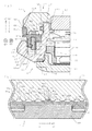
胴20の円筒状本体部21のうち下側の拡径円筒状部28には、リング状ないし環状のクリックばね40が遊嵌されている。クリックばね40は、図3の(a)及び(b)に示したように、三つの円弧状の基台部41a、41b、41c(相互に区別しないときや総称するときには符号41で示す)と、基台部41a、41b、41cの隣接端部をつなぐ三つの円弧状のばね部42a、42b、42c(相互に区別しないときや総称するときには符号42で示す)と、各ばね部42a、42b、42cの円弧の中央において前面側にA1方向に突出した係合突起部としてのクリック感付与突起部43a、43b、43c(相互に区別しないときや総称するときには符号43で示す)とを有する。ここで、三つの基台部41a、41b、41c、三つのばね部42a、42b、42c及び三つの係合突起部43a、43b、43cは、夫々、相互に同一の形状を有し、クリックばね40は、中心軸線を中心として、120度の回転に対して対称である。図3の(a)からわかるように、円弧状ばね部42は、円弧状基台部41と共通の外側円筒状周面44を有し、半径方向内側では、周面45に沿って凹部46を形成するように円弧状に切欠かれている。その結果、円弧状ばね部42の半径方向の厚さは、円弧状基台部41の半径方向の厚さよりも薄い。また、図3の(b)からわかるように、円弧状ばね部42は円弧状基台部41と共通の軸線方向前端面47を有し、軸線方向背面側では、端面48に沿って凹部49を形成するように円弧状に切欠かれている。その結果、円弧状ばね部42の軸線方向の厚さ(長さ)は、円弧状基台部41の軸線方向の厚さよりも薄い。従って、円弧状ばね部42は、円弧状基台部41と比較して半径方向及び軸線方向の切欠きないし凹部46、49を有することにより、剛性が低く、当該低剛性部分42において選択的に弾性変形可能になっている。なお、クリックばね40の内周面40i及び背面側(裏側)端面40rは、円弧状基台部41の内周面41i及び背面側端面41rに一致している。従って、クリックばね40は、背面側端面40rにおいて胴20のフランジ状部23の前面24のうち環状溝25よりも半径方向内側の部分24uに当接可能な状態で、内周面40iが胴20の拡径円筒状部28にほぼ接するように、胴20に嵌合されている。
【0019】
ばね部42は、リング状クリックばね40のうち周方向の三箇所に形成される代わりに、二箇所や四箇所でもよく、場合によっては、一箇所のみでもよい。また、ばね部42及び基台部41が複数個形成される場合、典型的には、複数個の夫々は相互に同一であるけれども、場合によっては、少なくとも一部又は全てが相互に異なる形状であってもよい。
【0020】
図5の(a)及び図2からわかるように、胴20のフランジ状部23の環状凹部25には、中心軸線Cの延在方向と平行に前後方向A1、A2方向に移動可能に、環状ストッパ50が配設されている。環状ストッパ50は、図4の(a)及び(b)に示したように、環状のストッパ本体部51と、環状ストッパ本体部51の前端面52の周方向の三箇所から前方A1に突出した突起部53a、53b、53c(相互に区別しないときや総称するときには符号53で示す)と、ストッパ本体部51の外周面54の後端近傍に形成された被係合部としての環状溝55と、ストッパ本体部51の内周面56の周方向の三箇所から半径方向内向きに突出した突起部57a、57b、57c(相互に区別しないときや総称するときには符号57で示す)とを有する。突起部57は、胴20の環状凹部25の内周面31のうち周方向に関して突起部57に対応する箇所に形成された前後方向A1、A2に延びるスプライン溝32に係合する。すなわち、図示の例のように、突起部57が120度間隔で三つ(57a、57b、57c)設けられている場合には、スプライン溝32も120度間隔で三箇所に設けられ、該溝32に突起部57で係合したストッパ50は、周方向B1、B2の回転が禁止された状態で前後方向A1、A2に移動可能に支えられる。突起部57は周方向に間隔をおいて二箇所以上あることが好ましく、突起部53の周方向配置とは独立であってもよい。但し、周方向からみた力や変形のバランスを保ったり、装着される際の向きの制約を最小限にするためには、図4の(a)に示したように、周方向に等間隔に且つ隣接突起部53に対して所定の相対配置で位置し、中心軸線Cのまわりでの回転に対して対称な形状であることが好ましい。突起部57は、ストッパ50の周方向回転を禁止するに適した形状であればよく、例えば、平面形状が、図4の(a)に示したようにドーム状ないし円弧状である代わりに、角のある四角形状や三角形状などでもよい。また、ストッパ50が十分な機械的な強度を備え得る場合には、ストッパ50の内周面56に前後方向A1、A2に延在するスプライン凹部を形成し、胴20の環状溝25の周面31に前後方向A1、A2に延在するスプライン突条を形成しておいてもよい。
【0021】
環状ストッパ50の突起部53すなわち突起部53a、53b、53cは、クリックばね40の背面側凹部49と丁度嵌り合う位置で、且つ丁度嵌り合う形状を有する。すなわち、凹部49が周方向に120度間隔で三箇所にある場合には、突起部53も周方向に120度間隔で三箇所にある。また、突起部53の周方向長さは凹部49の周方向長さとほぼ同じか該長さよりも僅かに小さい。一方、突起部53の前方A1への突出長は、典型的には、凹部49のA1方向深さよりも大きい。従って、環状ストッパ50は、突起部53の先端58がクリックばね40の凹部49の底面48に実際上当接してばね部42の背面A2側へのG1方向の撓み変形を禁止する位置E2(図6)と突起部53の先端58がクリックばね40の凹部49の底面48から十分に離れてばね部42の背面A2側への撓み変形を許容する位置E1(図5)との間で、前後方向A1、A2に移動可能である。なお、突起部53の前方A1への突出長は凹部49のA1方向深さと同程度でもよい。
【0022】
胴20の環状凹部25の外周側領域には、ストッパ変位手段としてのねじリング60が配設されている。ねじリング60は、小径円筒状部61と、小径円筒状部61の前側端部につながった大径円筒状部62と、小径円筒状部61の後側ないし背面側端部の内周面から半径方向内向きに突出した環状突起部63とを有する。環状突起部63は、ストッパ50の環状溝55に係合し、ねじリング60が前後方向A1、A2に移動される際、突起部63と溝55との係合を介して、ストッパ50を、係合解除許容位置E1(図5の(a)及び(b))とストッパ50の突起部53の頂面58がクリックばね40の凹部49の底面48のG1方向の後退を禁止する係合解除規制位置E2(図6の(a)及び(b))との間で、前後方向A1、A2に移動させる。なお、ストッパ50の環状溝55の背面側の壁部55aの背面の隅部及び突起部63の前面側の隅部は、突起部63の溝55への嵌込みを可能にすべく面取りされている。ねじリング60の小径円筒状部61の外周面には雄ねじ部64が形成され、雄ねじ部64は、胴20のフランジ状部23の雌ねじ部27に螺合されている。従って、ねじリング60を胴20に対してB1、B2方向に回転させると、ねじリング60は、胴20に対して例えばA1、A2方向に移動され、更に、部位55、63での係合により、ストッパ50をA1、A2方向に移動させる。ねじリング60の大径円筒状部62は、その背面側端面で胴20のフランジ状部23の前面24のうち外側部分24pに当接可能であり、更に、ローレット加工により形成されたスベリ止め用の縦溝66を外周面65に多数備える。従って、ねじリング60をB1、B2方向に回転させるためには、ねじリング60の大径円筒状部62の外周面65に指先を当ててねじリング60を回せばよい。
【0023】
胴20の円筒状部21には、胴20に対してB1、B2方向に回転可能に、ベゼル70が嵌合されている。べゼル70は、内周縁の突起71において胴20の円筒状部21の突起21aに係合して抜止めされている。72は、べゼル60のガタツキを防ぐためのリングである。べゼル70は、底壁73に凹凸としての環状凹部74を備え、凹部74の底面75は、頂部74a及び谷部74bに水平面75a、75bを有すると共に頂部水平面75a及び谷部水平面75bをつなぐ傾斜面75c、75dを有する。なお、図示の例では、頂部水平面75aは底壁73の水平面73aと実際上面一になっており、この場合、多数の実質的に同一形状の窪み76が全体として凹凸としての環状凹部74を形成するように等間隔で円形に並んでいることになる。但し、頂部水平面75aは底壁73の水平面73aと面一でなくてもよく、その場合、好ましくは、水平面73aよりも奥に位置する。
【0024】
傾斜面75c、75d及びこれらの間の谷部水平面74bにより規定される窪み76は、例えば、図5の(b)や図6の(b)に示したように、クリックばね40の係合突起部43の先端側の大半の部分が嵌込むようなほぼ相補的な形状を有する。べゼル70の窪み76が開口側程拡がるような傾斜面75c、75dを備えると共にクリックばね40の係合突起部43が中央部43aから離れるほどB1、B2方向に拡がる相補的形状の傾斜部43c、43dを備えるので、図5の(a)及び(b)に示したように、ストッパ50の突起部53の頂面58がクリックばね40の凹部49の底面48から離れた係合解除許容位置E1に位置する場合、べゼル70がB1又はB2方向に回転されると窪み76の傾斜面75c又は75dがクリックばね40の係合突起部43の傾斜部43c又は43dを窪み76の外に向かってほぼG1方向に押し出す。このとき、ばね40の円弧状ばね部42は、図5の(b)において想像線で示したように、凹部49の底面48がストッパ50の突起53の頂面58に接するか近接するように、撓み変形する。一方、べゼル40のB1またはB2方向の回転に伴って、ばね40の両持ちばね部42のうちG2方向に弾性偏倚された係合突起部43の頂部43aがべゼル70の鋸歯状歯状の頂部75aを乗り越えると、ばね部42の弾性により、係合突起部43がべゼル70の次の窪み76にG2方向に嵌り込む。従って、べゼル70は、クリック感がある状態で、B1、B2方向に回転可能である。
【0025】
一方、ねじリング60のB1方向回転により、図6の(a)及び(b)に示したように、該ねじリング60の突起部63に環状溝部55で係合したストッパ50をその突起部53の頂面58がクリックばね40の凹部49の底面48に近接する係合解除禁止位置E2に位置せしめた場合、べゼル70のB1、B2方向回転は禁止される。すなわち、べゼル70をB1又はB2方向に回転させ窪み76の傾斜面75c又は75dによってクリックばね40の係合突起部43の傾斜部43c又は43dをG1方向に窪み76の外に向かって押出そうとしても、ばね40の円弧状ばね部42は、図6の(b)からわかるとおり、凹部49に底面48まで嵌ったストッパ50の突起53でG1方向変位が禁止されているので、ばね部42が弾性変形されないから、べゼル70はB1方向にもB2方向にも回転され得ない。
【0026】
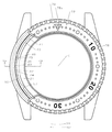
なお、べゼル70の表面77には、目盛78が付されている。従って、例えば、潜水を開始する前に、ねじリング60をB2方向に回しストッパ50を係合解除許容位置E1にA2方向に移動させておいて、べゼル70の目盛78の原点位置78aを例えば潜水開始時点の時刻(図示の例では分針の位置)にあわせるように回転させておく。べゼル70の目盛78の原点位置78aに位置決めが完了したら、ねじリング60をB1方向に回しストッパ50を係合解除禁止位置E2にA1方向に移動させる。これによって、べゼル70の不測の回転が禁止される。従って、潜水開始後の時間がわかることになる。なお、目盛78を反時計回りに付けておいて、潜水時間の代わりに残りの許容潜水時間が時計の針の位置から直接視認可能にしておいてもよい。図1において、79は、べゼル70を回転させる際、指先を当てるスベリ止を兼ねた凹凸からなる飾り縁で、ローレット加工等で形成されている。
【0027】
以上の如く構成された本発明による好ましい第一実施例の回転式べゼル装置1を備えた携帯時計2がダイバーズウオッチからなる場合、潜水などの開始前に、回転式べゼル装置1のべゼル70を現在時刻又は潜水開始予定時刻に合わせる。
【0028】
このために、まず、ねじリング60をB1方向に回してA2方向に移動させることにより、被係合部としての環状溝55が係合部としての突起部63に係合されたストッパ50を図5の係合解除許容位置ないしアンロック位置E1に設定する。
【0029】
次に、べゼル70のスベリ止付き飾り縁(ローレット加工部)79を指先でつまんで、べゼル70の目盛78の始点78aが、現在時刻又は潜水開始予定時刻における分針の位置に一致するところまで、べゼル70を胴20に対してB1方向又はB2方向に回転させる。この回転方向としては、例えば、回し易い方向やそのときの始点78aの位置から指定すべき位置までの角度が小さい方を選べばよい。万一、所定位置を越えて回し過ぎた場合には、逆方向に僅かに回転させて所定位置に合わせればよい。ストッパ50が位置E1にある場合には、クリックばね40のばね部42の凹部49の底面48とストッパ50の突起部53の頂面58との間に間隙があるので、クリックばね40のばね部42がG1方向に撓み得るから、べゼル70は、その窪み76の傾斜面75d又は75cでクリックばね40の先端係合部47の対応する傾斜部43cまたは43dをほぼG1方向に押してばね部42をG1方向に撓ませながら、B1又はB2方向に回転され得る。この回転の際、べゼル70が所定ピッチ(角度)回転されるごとに、クリックばね40の先端係合部43がべゼル70の底面73の凹凸74の窪み76に入ったり出たりするので、べゼル70のB1又はB2方向回転に際して、所望のクリック感が得られる。このようにして、クリックばね40の先端係合部43がべゼル70の窪み76に丁度嵌込むように窪み76に係合する位置においてべゼル70の所望位置への回転ないし位置決めが完了する。
【0030】
次に、ねじリング60のローレット溝65に指を当ててねじリング60をB1方向に回し、ねじリング60の小径円筒状部61の頂面61aがべゼル70の底面73に近接するところまでねじリング60をA1方向に移動させ、ストッパ50の係合突起部53が、クリックばね40の凹部49の底面48に近接又はほぼ当接するまで胴20に対してストッパ50をA1方向に移動させることにより、ストッパ50を係合解除許容位置(アンロック位置)E1から係合解除禁止位置(ロック位置)E2に移動させる。これによって、ストッパ50は、底部の係合突起部53がクリックばね40のばね部42の背面の凹部49に丁度嵌りこんで位置決めされる。
【0031】
ストッパ50が位置E2に達すると、図6の(a)及び(b)からわかるように、ストッパ50の係合突起部53の頂面58がクリックばね40のばね部42の背面側の凹部49の底面48に実質的に当接する。その結果、クリックばね40のばね部42のG1方向への撓み変形が、ストッパ50により、禁止される。従って、ストッパ50を位置E2に設定した状態では、べゼル70をB1方向に回転させようしてもB2方向に回転させようとしても、ストッパ50により背面48で支えられたクリックばね40のばね部42が逃げる余地がないので、係合突起部43でべゼル70の窪み76に係合したクリックばね40がべゼル70の回転を規制ないし禁止する。即ち、べゼル70に不測の回転が生じる虞れが実際上ない。
【0032】
なお、図5及び図6に示したように、ストッパ50の突起部53が、クリックばね40の係合突起43の背面にある凹部49に嵌ってばね40の係合突起43とべゼル70の窪み76との係合や該係合の解除を制御する代わりに、図7及び図8に示したように、ストッパ50の突起部53Aがクリックばね40を越えてべゼル70の窪み76内に直接的に突出・係合可能になっていてもよい。ストッパ50のこの突起部53Aは、図7の(b)及び図8の(b)に示した例では、クリックばね40に形成された孔40aを貫通してべゼル70の窪み76に直接延びる。なお、孔40aは、溝などであってもよい。また、図7及び8に示した例のネジリング60Aでは、図5や図6のねじリング60の縦溝66の代わりに、リング66Aが嵌められている。リング66Aは、例えば、スベリ止めとして働くプラスチック又はゴム製材料からなり、所望に応じた種々のカラー(色)を有し得る。
【図面の簡単な説明】
【図1】本発明による好ましい一実施例の回転式べゼル装置を備えた携帯時計の一部破断平面説明図。
【図2】図1の携帯時計の回転式べゼル装置のうちべゼル以外の主な部材(胴、クリックばね、ストッパ及びねじリング)の配置の一例を示した斜視説明図。
【図3】図1及び図2の回転式べゼル装置のクリックばねを示したもので、(a)は平面説明図、(b)は正面(側面)説明図。
【図4】図1及び図2の回転式べゼル装置のストッパを示したもので、(a)は平面説明図、(b)は正面(側面)説明図、(c)は(a)のIVC−IVC線断面説明図。
【図5】図1の携帯時計において、べゼルの回転が許容されている状態におけるべゼルとクリックばねとストッパとの位置関係を示したもので、(a)は図1の携帯時計のVA−VA線断面説明図、(b)は(a)のVB−VB線断面説明図。
【図6】図1の携帯時計において、べゼルの回転が禁止されている状態におけるべゼルとクリックばねとストッパとの位置関係を示したもので、(a)は図5の(a)と同様な断面で見た断面説明図、(b)は(a)のVIB−VIB線断面説明図。
【図7】変形例についての図5と同様な説明図であって、(a)は図5の(a)と同様な断面説明図、(b)は(a)のVIIB−VIIB線断面説明図。
【図8】変形例についての図6と同様な説明図であって、(a)は図6の(a)と同様な断面説明図、(b)は(a)のVIIIB−VIIIB線断面説明図。
【符号の説明】
1 回転式べゼル装置
2 携帯時計
20 胴
24 環状凹部
26 切欠
40 クリックばね
41 基台部
42 ばね部
43 係合突起部
50 ストッパ
53 突起部
55 環状溝部
60 ねじリング
63 係合突起部
70 べゼル
74 環状凹部
75c、75d 傾斜面部
76 窪み[0001]
BACKGROUND OF THE INVENTION
The present invention relates to a rotary bezel device suitable for use in a portable timepiece with a rotating bezel such as a divers watch, and a portable timepiece having the same.
[0002]
[Prior art]
Mounted on the barrel so that it can rotate around the central axis of the barrel, and the bezel with irregularities at regular angular intervals along the circumferential direction. A portable timepiece with a rotating bezel such as a diver's watch having a spring that is elastically engageable with a body is known. In this type of portable timepiece, the bezel has a scale in the circumferential direction. For example, the bezel is set so that the origin or start point of the bezel scale is aligned with the position of the hand (for example, the minute hand) at the start of diving. Rotate and start diving. In this case, the dive time can be directly visually recognized by reading the position of the minute hand of the watch on the scale of the bezel.
[0003]
[Problems to be solved by the invention]
However, in this type of conventional portable timepiece with a rotating bezel, when an unexpected external force is applied to the bezel, the protruding portion of the spring is pushed out from the depression by the side wall of the concave / convex depression of the bezel. There is a possibility that the bezel is rotated because the engagement with the protrusion of the spring is released. As a result, there is a possibility that the diving time cannot be accurately known during diving.
[0004]
The present invention has been made in view of the above-described points, and an object of the present invention is to provide a rotary bezel device that is practically free from the possibility of unexpected rotation after being positioned, and a portable device including the rotary bezel device. To provide a watch.
[0005]
[Means for Solving the Problems]
In order to achieve the above-mentioned object, the rotary bezel device of the present invention is mounted on the body and the body so as to be rotatable about the central axis of the body, and is uneven at regular angular intervals along the circumferential direction. And at least one arcuate base portion supported by the body portion, and adjacent ends of the arcs of the at least one base portion to form a ring in cooperation with the base portion. An annular spring structure having at least one arcuate spring portion to be connected and an engaging projection that protrudes toward the bezel in the middle of the arc of the spring portion and elastically engages with the irregularities of the bezel; And a stopper that is movably mounted on the body between a rotation permission position that allows rotation of the lens and a rotation prohibition position that prohibits rotation of the bezel.
[0006]
In the rotary bezel device of the present invention, “at least one arcuate base portion supported by the body portion and the at least one base portion to form a ring in cooperation with the base portion. And at least one arc-shaped spring portion that connects adjacent ends of the arc, and an engaging protrusion that protrudes toward the bezel in the middle of the arc of the spring portion and elastically engages with the irregularities of the bezel. Since the "annular spring structure" is provided, when the bezel is rotated, the engagement between the protrusion of the spring structure and the concave and convex recesses of the bezel is released against the spring force of the annular spring structure. A sense of resistance is imparted when When the projecting portion passes over the uneven convex portion and fits into the next concave portion by the spring force of the spring portion, the sense of resistance is practically lost, and a click feeling is obtained as a whole. Moreover, in the rotary bezel device of the present invention, in particular, the “stopper movably mounted on the body between the rotation allowable position that allows the bezel to rotate and the rotation prohibited position that prohibits the bezel from rotating” is provided. Thus, if the stopper is set at the rotation prohibition position after the bezel is rotated and positioned at the predetermined position, unexpected rotation of the bezel can be prohibited. Here, when rotating the bezel, the stopper is set to the rotation allowable position.
[0007]
In the rotary bezel device of the present invention, since the spring structure is annular and the arcuate spring part is connected to the adjacent end part of the base part, the arcuate spring part is formed by the base part at both ends thereof. Since it is supported, the support of the arc-shaped spring portion becomes more stable as compared with the case where the spring is cantilevered.
[0008]
Although at least one base and arcuate spring portion are required, for the stability of the ring, there are typically at least two places, typically two or three places on the ring, and the circumference of each element. The central portions in the direction are alternately arranged so as to be positioned at equiangular intervals of 180 degrees or 120 degrees. As a result, an average force can be applied to the ring in a balanced manner.
[0009]
In the rotary bezel device of the present invention, typically, “the stopper is close to and away from the bezel between the rotation allowable position and the rotation prohibition position and is engaged in the circumferential direction. And an annular stopper displacing means that is engaged with the engaged portion of the stopper at the engaging portion and screwed into the trunk portion with a helical groove. Accordingly, the annular stopper displacing means engaged with the trunk portion by the spiral groove is rotated, that is, rotationally displaced with respect to the trunk portion. Thus, the stopper engaged by the engaged portion with the engaging portion of the stopper displacing means can be displaced in the extending direction of the rotation center axis. Therefore, the stopper can be moved close to and away from the bezel, and the stopper can be moved between the rotation allowable position and the rotation prohibited position. That is, in the rotary bezel device of the present invention, typically, the stopper can be moved between the rotation allowable position and the rotation prohibited position by rotating the annular stopper displacement means. The “screwing by the spiral groove” is not limited to the screwing by the so-called threaded portion, and any engagement may be used as long as the engagement can be converted into translation.
[0010]
Here, even if the stopper is directly engaged with the unevenness of the bezel to restrict the rotation of the bezel, the stopper is indirectly engaged with the unevenness of the bezel via the annular spring structure. The rotation of the gel may be restricted.
[0011]
In the former case, when the stopper is in the rotation prohibition position, the stopper includes a rotation prohibition protrusion that engages with the unevenness of the bezel. In that case, typically, the spring structure includes a notch, and the rotation prohibiting protrusion of the stopper extends through the notch of the spring structure to the unevenness of the bezel. Here, the cutout portion of the spring structure is typically a through hole, but may be a groove.
[0012]
In the latter case, when the stopper is in the rotation prohibition position, the engagement release prohibiting protrusion that prohibits the engagement between the engaging protrusion in the middle of the spring portion of the spring structure and the unevenness of the bezel is released. When the stopper is provided and the stopper is in the rotation-permitted position, the disengagement prohibiting protrusion of the stopper moves backward to a position that allows disengagement between the engaging protrusion and the unevenness of the bezel. In that case, the engaging protrusions of the spring structure can be used together to restrict the rotation of the bezel. Also, in this case, typically, the spring structure has a recess on the back side of the spring portion, and when the stopper is in the rotation prohibition position, the stopper disengagement prohibiting protrusion engages with the recess of the spring structure. To do. This makes it possible to widen the stopper disengagement prohibiting protrusion of the stopper, and the rotation of the spring structure is restricted by the wide disengagement prohibiting protrusion through the back side recess of the spring structure, Inhibiting the rotation of the bezel can be easily performed.
[0013]
Such a rotating bezel device is typically incorporated in a portable watch such as a watch such as a divers watch. In that case, the body of the bezel device typically forms the body of the portable watch itself. However, in some cases, the rotating bezel device may be incorporated in another device.
[0014]
DETAILED DESCRIPTION OF THE INVENTION
Next, some preferred embodiments of the present invention will be described based on preferred examples shown in the accompanying drawings.
[0015]
【Example】
1 to 6 show a portable timepiece 2 having a
[0016]
The portable timepiece 2 includes a ring-shaped
[0017]
The flange-
[0018]
A ring-shaped or
[0019]
The spring portion 42 may be formed at two locations in the circumferential direction of the ring-shaped
[0020]
As can be seen from FIG. 5A and FIG. 2, the
[0021]
The
[0022]
A
[0023]
A
[0024]
The
[0025]
On the other hand, when the
[0026]
A
[0027]
When the portable timepiece 2 having the
[0028]
For this purpose, first, the
[0029]
Next, the decorative edge (knurled part) 79 of the
[0030]
Next, a finger is applied to the knurled groove 65 of the
[0031]
When the
[0032]
As shown in FIGS. 5 and 6, the
[Brief description of the drawings]
FIG. 1 is a partially broken plan view of a portable timepiece having a rotary bezel device according to a preferred embodiment of the present invention.
2 is an explanatory perspective view showing an example of the arrangement of main members (a trunk, a click spring, a stopper, and a screw ring) other than the bezel in the rotary bezel device of the portable timepiece of FIG. 1;
FIGS. 3A and 3B show a click spring of the rotary bezel device of FIGS. 1 and 2, in which FIG. 3A is a plan explanatory view, and FIG. 3B is a front (side) explanatory view.
FIGS. 4A and 4B show a stopper of the rotary bezel device of FIGS. 1 and 2, wherein FIG. 4A is a plan explanatory view, FIG. 4B is a front (side) explanatory view, and FIG. IVC-IVC line sectional explanatory drawing.
5 shows the positional relationship among the bezel, the click spring, and the stopper in a state in which the bezel rotation is allowed in the portable timepiece of FIG. 1, (a) is a VA of the portable timepiece of FIG. -VA sectional view explanatory drawing, (b) VB-VB sectional explanatory drawing of (a).
6 shows the positional relationship between the bezel, the click spring, and the stopper in a state in which the rotation of the bezel is prohibited in the portable timepiece of FIG. 1, wherein (a) is the same as (a) of FIG. Cross-sectional explanatory drawing seen in the same cross section, (b) is VIB-VIB sectional view explanatory drawing of (a).
7A and 7B are explanatory diagrams similar to FIG. 5, in which FIG. 7A is a cross-sectional explanatory view similar to FIG. 5A, and FIG. 7B is a cross-sectional explanatory view taken along the line VIIB-VIIB in FIG. Figure.
8A and 8B are explanatory views similar to FIG. 6, in which FIG. 8A is a cross-sectional explanatory view similar to FIG. 6A, and FIG. 8B is a cross-sectional description along line VIIIB-VIIIB in FIG. Figure.
[Explanation of symbols]
1 Rotating bezel device
2 Mobile watch
20 torso
24 annular recess
26 Notch
40 click spring
41 Base
42 Spring
43 Engaging protrusion
50 stopper
53 Projection
55 Annular groove
60 thread ring
63 Engaging protrusion
70 bezel
74 Annular recess
75c, 75d inclined surface
76 Dimple
Claims (7)
前記胴部の中心軸線のまわりで回転可能に前記胴部に装着され周方向に沿って規則的な角度間隔で凹凸を備えたべゼルと、
前記胴部によって支持された少なくとも一つの円弧状の基台部、該基台部と協働して環を形成すべく前記少なくとも一つの基台部の円弧の隣接端部をつなぐ少なくとも一つの円弧状のばね部及び該ばね部の円弧の中間においてべゼルに向かって突出し前記べゼルの凹凸に弾性的に係合する係合突起部を備えた環状ばね構造体と、
前記べゼルの回転を許容する回転許容位置と前記べゼルの回転を禁止する回転禁止位置との間で可動に前記胴部に装着されたストッパと
を有し、
前記ストッパが、前記回転許容位置と前記回転禁止位置との間で前記べゼルに対して近接離間可能で、且つ周方向に延びた被係合部を備え、係合部で前記ストッパの前記被係合部に係合し且つ前記胴部に対して螺旋溝で螺合された環状のストッパ変位手段を更に有する回転式べゼル装置。The torso,
A bezel that is mounted on the barrel so as to be rotatable about the central axis of the barrel and has irregularities at regular angular intervals along the circumferential direction;
At least one circular base supported by the body, and at least one circle connecting adjacent ends of the circular arc of the at least one base so as to form a ring in cooperation with the base; An annular spring structure provided with an arcuate spring portion and an engaging projection that protrudes toward the bezel in the middle of the arc of the spring portion and elastically engages with the irregularities of the bezel;
A stopper that is movably mounted between the rotation allowable position that allows rotation of the bezel and the rotation prohibition position that prohibits rotation of the bezel ;
The stopper includes an engaged portion that can be moved toward and away from the bezel between the rotation allowable position and the rotation prohibited position, and extends in a circumferential direction. A rotary bezel device further comprising an annular stopper displacing means that engages with an engaging portion and is screwed into the body portion with a spiral groove .
前記胴部の中心軸線のまわりで回転可能に前記胴部に装着され周方向に沿って規則的な角度間隔で凹凸を備えたべゼルと、
前記胴部によって支持された少なくとも一つの円弧状の基台部、該基台部と協働して環を形成すべく前記少なくとも一つの基台部の円弧の隣接端部をつなぐ少なくとも一つの円弧状のばね部及び該ばね部の円弧の中間においてべゼルに向かって突出し前記べゼルの凹凸に弾性的に係合する係合突起部を備えた環状ばね構造体と、
前記べゼルの回転を許容する回転許容位置と前記べゼルの回転を禁止する回転禁止位置との間で可動に前記胴部に装着されたストッパと
を有し、
前記ストッパが前記回転禁止位置にある際、前記べゼルの凹凸に係合する前記回転禁止突起を前記ストッパが備える回転式べゼル装置。 The torso,
A bezel that is mounted on the barrel so as to be rotatable about the central axis of the barrel and has irregularities at regular angular intervals along the circumferential direction;
At least one circular base supported by the body, and at least one circle connecting adjacent ends of the circular arc of the at least one base so as to form a ring in cooperation with the base; An annular spring structure provided with an arcuate spring portion and an engaging projection that protrudes toward the bezel in the middle of the arc of the spring portion and elastically engages with the irregularities of the bezel;
A stopper mounted on the body portion movably between a rotation allowable position allowing rotation of the bezel and a rotation prohibiting position prohibiting rotation of the bezel;
Have
A rotary bezel device , wherein the stopper includes the rotation prohibiting protrusion that engages with the unevenness of the bezel when the stopper is in the rotation prohibiting position .
Priority Applications (1)
| Application Number | Priority Date | Filing Date | Title |
|---|---|---|---|
| JP2002003491A JP3730173B2 (en) | 2002-01-10 | 2002-01-10 | Rotating bezel device and portable watch equipped with the same |
Applications Claiming Priority (1)
| Application Number | Priority Date | Filing Date | Title |
|---|---|---|---|
| JP2002003491A JP3730173B2 (en) | 2002-01-10 | 2002-01-10 | Rotating bezel device and portable watch equipped with the same |
Publications (2)
| Publication Number | Publication Date |
|---|---|
| JP2003207581A JP2003207581A (en) | 2003-07-25 |
| JP3730173B2 true JP3730173B2 (en) | 2005-12-21 |
Family
ID=27643069
Family Applications (1)
| Application Number | Title | Priority Date | Filing Date |
|---|---|---|---|
| JP2002003491A Expired - Lifetime JP3730173B2 (en) | 2002-01-10 | 2002-01-10 | Rotating bezel device and portable watch equipped with the same |
Country Status (1)
| Country | Link |
|---|---|
| JP (1) | JP3730173B2 (en) |
Families Citing this family (3)
| Publication number | Priority date | Publication date | Assignee | Title |
|---|---|---|---|---|
| JP4595382B2 (en) * | 2004-05-14 | 2010-12-08 | セイコーエプソン株式会社 | Watch case and watch |
| JP2006314347A (en) * | 2005-05-10 | 2006-11-24 | Seiko Instruments Inc | Band for watch, and wrist-watch |
| JP6835123B2 (en) * | 2019-03-25 | 2021-02-24 | カシオ計算機株式会社 | Rotating device and clock |
-
2002
- 2002-01-10 JP JP2002003491A patent/JP3730173B2/en not_active Expired - Lifetime
Also Published As
| Publication number | Publication date |
|---|---|
| JP2003207581A (en) | 2003-07-25 |
Similar Documents
| Publication | Publication Date | Title |
|---|---|---|
| JP4695497B2 (en) | Watch with interchangeable bezel | |
| US6821014B2 (en) | Rotating-type bezel apparatus and portable timepiece having rotating-type bezel apparatus | |
| JP6087160B2 (en) | Watch case with orientable index bezel | |
| JP4882362B2 (en) | Vehicle seat reclining device | |
| JP4850008B2 (en) | clock | |
| JP4878339B2 (en) | clock | |
| JP6384061B2 (en) | Seat reclining device | |
| US6599009B2 (en) | Wristwatch case having a rotary bezel | |
| JP6237325B2 (en) | Seat reclining device | |
| TWM459071U (en) | Ratchet wrench structure | |
| WO2001075530A1 (en) | Wristwatch case with rotary bezel | |
| JP3730173B2 (en) | Rotating bezel device and portable watch equipped with the same | |
| US8051747B1 (en) | One-way ratchet wrench | |
| JP2007298671A (en) | Optical option mounting ring | |
| JP6821760B2 (en) | Locking mechanism for operating members and watches with them | |
| JP2007132779A (en) | Winding crown structure for timepiece | |
| JP6919645B2 (en) | Switch device and clock | |
| JP3810691B2 (en) | Cell phone clock | |
| JP4595382B2 (en) | Watch case and watch | |
| TWI825944B (en) | Ratchet wrench structure | |
| JP4214059B2 (en) | Rotating bezel | |
| JP2022035127A (en) | Case and timepiece | |
| JP3205115U (en) | Ring tablets | |
| JP6123834B2 (en) | Lock member, switch device, and clock | |
| JP4760146B2 (en) | helmet |
Legal Events
| Date | Code | Title | Description |
|---|---|---|---|
| RD01 | Notification of change of attorney |
Free format text: JAPANESE INTERMEDIATE CODE: A7421 Effective date: 20040304 |
|
| A621 | Written request for application examination |
Free format text: JAPANESE INTERMEDIATE CODE: A621 Effective date: 20040928 |
|
| A977 | Report on retrieval |
Free format text: JAPANESE INTERMEDIATE CODE: A971007 Effective date: 20050523 |
|
| A131 | Notification of reasons for refusal |
Free format text: JAPANESE INTERMEDIATE CODE: A131 Effective date: 20050531 |
|
| A521 | Request for written amendment filed |
Free format text: JAPANESE INTERMEDIATE CODE: A523 Effective date: 20050801 |
|
| TRDD | Decision of grant or rejection written | ||
| A01 | Written decision to grant a patent or to grant a registration (utility model) |
Free format text: JAPANESE INTERMEDIATE CODE: A01 Effective date: 20051004 |
|
| A61 | First payment of annual fees (during grant procedure) |
Free format text: JAPANESE INTERMEDIATE CODE: A61 Effective date: 20051005 |
|
| R150 | Certificate of patent or registration of utility model |
Ref document number: 3730173 Country of ref document: JP Free format text: JAPANESE INTERMEDIATE CODE: R150 Free format text: JAPANESE INTERMEDIATE CODE: R150 |
|
| FPAY | Renewal fee payment (event date is renewal date of database) |
Free format text: PAYMENT UNTIL: 20091014 Year of fee payment: 4 |
|
| FPAY | Renewal fee payment (event date is renewal date of database) |
Free format text: PAYMENT UNTIL: 20091014 Year of fee payment: 4 |
|
| FPAY | Renewal fee payment (event date is renewal date of database) |
Free format text: PAYMENT UNTIL: 20101014 Year of fee payment: 5 |
|
| FPAY | Renewal fee payment (event date is renewal date of database) |
Free format text: PAYMENT UNTIL: 20101014 Year of fee payment: 5 |
|
| RD03 | Notification of appointment of power of attorney |
Free format text: JAPANESE INTERMEDIATE CODE: R3D03 |
|
| FPAY | Renewal fee payment (event date is renewal date of database) |
Free format text: PAYMENT UNTIL: 20101014 Year of fee payment: 5 |
|
| FPAY | Renewal fee payment (event date is renewal date of database) |
Free format text: PAYMENT UNTIL: 20111014 Year of fee payment: 6 |
|
| FPAY | Renewal fee payment (event date is renewal date of database) |
Free format text: PAYMENT UNTIL: 20111014 Year of fee payment: 6 |
|
| FPAY | Renewal fee payment (event date is renewal date of database) |
Free format text: PAYMENT UNTIL: 20121014 Year of fee payment: 7 |
|
| FPAY | Renewal fee payment (event date is renewal date of database) |
Free format text: PAYMENT UNTIL: 20121014 Year of fee payment: 7 |
|
| FPAY | Renewal fee payment (event date is renewal date of database) |
Free format text: PAYMENT UNTIL: 20131014 Year of fee payment: 8 |
|
| R250 | Receipt of annual fees |
Free format text: JAPANESE INTERMEDIATE CODE: R250 |
|
| R250 | Receipt of annual fees |
Free format text: JAPANESE INTERMEDIATE CODE: R250 |
|
| R250 | Receipt of annual fees |
Free format text: JAPANESE INTERMEDIATE CODE: R250 |
|
| R250 | Receipt of annual fees |
Free format text: JAPANESE INTERMEDIATE CODE: R250 |
|
| R250 | Receipt of annual fees |
Free format text: JAPANESE INTERMEDIATE CODE: R250 |
|
| EXPY | Cancellation because of completion of term |