JP3729068B2 - Operating parts, manufacturing method thereof and equipment - Google Patents
Operating parts, manufacturing method thereof and equipment Download PDFInfo
- Publication number
- JP3729068B2 JP3729068B2 JP2000376299A JP2000376299A JP3729068B2 JP 3729068 B2 JP3729068 B2 JP 3729068B2 JP 2000376299 A JP2000376299 A JP 2000376299A JP 2000376299 A JP2000376299 A JP 2000376299A JP 3729068 B2 JP3729068 B2 JP 3729068B2
- Authority
- JP
- Japan
- Prior art keywords
- head
- support
- shaft portion
- operation button
- shaft
- Prior art date
- Legal status (The legal status is an assumption and is not a legal conclusion. Google has not performed a legal analysis and makes no representation as to the accuracy of the status listed.)
- Expired - Fee Related
Links
- 238000004519 manufacturing process Methods 0.000 title claims description 12
- 239000000463 material Substances 0.000 claims description 52
- 229920005989 resin Polymers 0.000 claims description 11
- 239000011347 resin Substances 0.000 claims description 11
- 238000000465 moulding Methods 0.000 claims description 10
- 238000004080 punching Methods 0.000 claims description 5
- 238000000034 method Methods 0.000 claims description 3
- 239000012778 molding material Substances 0.000 claims description 2
- 229920003002 synthetic resin Polymers 0.000 description 7
- 239000000057 synthetic resin Substances 0.000 description 7
- 238000003825 pressing Methods 0.000 description 6
- 230000035807 sensation Effects 0.000 description 6
- 239000002184 metal Substances 0.000 description 5
- 238000012856 packing Methods 0.000 description 4
- 239000007779 soft material Substances 0.000 description 4
- 239000002344 surface layer Substances 0.000 description 4
- 239000013013 elastic material Substances 0.000 description 3
- 229920001971 elastomer Polymers 0.000 description 3
- 230000004048 modification Effects 0.000 description 3
- 238000012986 modification Methods 0.000 description 3
- 239000005060 rubber Substances 0.000 description 3
- 230000001788 irregular Effects 0.000 description 2
- 239000007769 metal material Substances 0.000 description 2
- 238000003801 milling Methods 0.000 description 2
- 238000003672 processing method Methods 0.000 description 2
- 229920003051 synthetic elastomer Polymers 0.000 description 2
- 239000005061 synthetic rubber Substances 0.000 description 2
- 238000003466 welding Methods 0.000 description 2
- JOYRKODLDBILNP-UHFFFAOYSA-N Ethyl urethane Chemical compound CCOC(N)=O JOYRKODLDBILNP-UHFFFAOYSA-N 0.000 description 1
- 230000008878 coupling Effects 0.000 description 1
- 238000010168 coupling process Methods 0.000 description 1
- 238000005859 coupling reaction Methods 0.000 description 1
- 230000000694 effects Effects 0.000 description 1
- 239000011521 glass Substances 0.000 description 1
- 210000004247 hand Anatomy 0.000 description 1
- 230000001771 impaired effect Effects 0.000 description 1
- 238000005304 joining Methods 0.000 description 1
- 238000003754 machining Methods 0.000 description 1
- 238000007789 sealing Methods 0.000 description 1
- 229910001220 stainless steel Inorganic materials 0.000 description 1
- 239000010935 stainless steel Substances 0.000 description 1
- 210000000707 wrist Anatomy 0.000 description 1
Images

Landscapes
- Manufacture Of Switches (AREA)
- Electric Clocks (AREA)
Description
【0001】
【発明の属する技術分野】
本発明は操作部品及びその製造方法並びに機器に係り、特に、腕時計その他の機器の操作ボタンを構成する部品として好適な部品構造に関する。
【0002】
【従来の技術】
一般に、腕時計の時計本体の側部に取り付けられた操作ボタンやリュウズは、操作を受けるように形成された頭部と、この頭部よりも小さな断面を有する軸部とを備えている。軸部は時計ケースを貫通して時計本体内に導入され、その内端部が接点バネ等に当接するように構成されている。
【0003】
図4は、従来の操作ボタンの形状を模式的に示す概略端面図(a)〜(c)である。図4(a)に示す操作ボタン10は、頭部11と、この頭部11の背後に伸びるように形成された軸部12とを備えている。ここで、頭部11は軸部12の断面よりも大きな面積の平面形状を有するように形成されている。また、頭部の軸部12側の部分には、操作ボタン10を突出する方向に押し出すために時計本体との間に配置されるコイルバネの一部、或いは、時計本体を貫通するように接合されたパイプ部材の先端を収容するための凹部11aが形成されている。さらに、軸部12には、時計本体の密封性を確保するためのパッキンを収容するための環状溝12aと、その内端部の近傍において時計本体から操作ボタン10が抜け出ないようにするために取り付けられる止め輪を係合させるための環状溝12bとが設けられている。
【0004】
図4(b)に示す操作ボタン20は、上記と同様に頭部21と軸部22とからなるものである。この場合には頭部21と軸部22とが別体に構成され、頭部21に設けられた穴内に軸部22の先端が圧入されている。この場合には頭部21は合成樹脂で形成することも可能である。また、頭部21を金属で形成した場合には、頭部21と軸部22をカシメ加工等によって固着してもよい。
【0005】
図4(c)に示す操作ボタン30は、軸部32の先端部に対してインサート成形によって合成樹脂製の頭部31を一体に成形したものである。また、この頭部31の表面上には、別の樹脂等からなる表面層33をコーティングしている。
【0006】
【発明が解決しようとする課題】
しかしながら、図4(a)に示すように頭部11と軸部12とが一体に形成されている操作ボタン10を製造する場合には、複雑な構造を一体に成形しなければならないとともに、旋削等の比較的容易な加工方法だけでは非円形断面(例えば楕円断面、角型断面など)を有する異形の頭部を形成することができないので、フライス加工等のように手間のかかる加工方法を用いる必要があり、加工コストが高くなるという問題点がある。
【0007】
また、操作ボタンやリュウズには良好な触感と確実な操作性とが要求されるが、図4(a)に示す一体の操作ボタン10では頭部11も金属製であるので硬く冷たい触感しか得られないという問題点がある。また、図4(b)に示すように頭部21と軸部22とが別体になっている場合には、頭部21を軟質樹脂や合成ゴム等によって形成することによって柔らかな触感を得ることができるが、頭部21が柔らかくなることによって軸部22から脱落しやすくなるとともに操作を軸部に伝達しにくくなり確実な操作が難しくなる傾向がある。さらに、図4(c)に示す操作ボタン30において、頭部31の表面上に形成される表面層33を軟質樹脂等の触感の比較的良好な素材で形成することもできるが、この場合には表面層33の厚さに限りがあるために触感の改善にも限界があり、また、継続的な使用により表面層33が磨耗して頭部31が露出し、高級感を損なう場合がある。
【0008】
そこで本発明は上記問題点を解決するものであり、その課題は、操作ボタン等の操作部品の加工コストを低減できる新規な構造を提供することにある。また、操作部品の触感、操作性及び耐久性を高次元で満たすことのできる新規な構造を提供することにある。
【0009】
【課題を解決するための手段】
上記課題を解決するために本発明の操作部品は、操作を受けるための頭部と、操作を伝えるために前記頭部の背後に伸びる軸部とを備えた操作部品において、前記頭部の背後を支持可能に支持材が配置され、該支持材が前記軸部に結合されており、前記頭部は樹脂材料で構成されていると共に、この樹脂材料が前記支持材の側面を経由して背後に回り込んで構成されていることを特徴とする。
【0010】
この発明によれば、頭部を支持可能に支持材が配置されていることによって、操作時において頭部を支持材にて支持することができるように構成することで、頭部を軟質材や弾性材によって形成しても、支持材に充分な剛性を持たせることにより、頭部に加えられる操作を確実に軸部へと伝達することが可能になるから、頭部の触感と操作性とを両立することができる。
【0011】
ここで、頭部と支持材とが結合されているとともに支持材と軸部とが結合されているものであってもよく、また、頭部と軸部とが結合されているとともに支持材と軸部とが結合されているものであっても構わない。すなわち、頭部と支持材とは直接に結合されていなくても、支持材が頭部を支持可能に配置されていればよい。また、頭部と軸部、或いは、支持材と軸部との結合態様としては、頭部を支持する支持材から軸部へと操作を伝達可能に接続されていればよく、必ずしもカシメやロー付けなどによって機械的に固定されている必要はない。
【0012】
本発明において、前記頭部を支持する前記支持材の支持面が前記軸部の断面よりも広いことが好ましい。この手段によれば、支持材の支持面が軸部の断面よりも広いことにより、頭部を広い面積で支持することができるので、軸部の軸線からずれた頭部の部位を押圧操作しても支障なく操作可能になるなど、頭部に対する操作をより確実に軸部へと伝達できる。
【0013】
本発明において、前記支持面が前記頭部の平面形状と略相似の形状を備えていることが好ましい。頭部の平面形状と略相似の形状の支持面によって頭部が支持されるので、頭部の平面形状が軸部の軸線周りに対象性の低い異形状(軸線中心の円形と異なる平面形状)を備えていても、支持材を介して操作を確実に軸部へ伝達することができる。
【0014】
本発明において、前記支持材が前記頭部よりも高い剛性を有することが好ましい。この手段によれば、支持材が頭部よりも高剛性であるために、頭部を確実に支持することができ、頭部に対する操作を支持材で確実に受け止め、これを軸部に確実に伝達することが可能になる。
【0015】
本発明において、前記支持材が板状体であることが好ましい。この手段によれば、支持材を板状体とすることにより、プレス加工等の板状材の打ち抜き加工、ワイヤ放電加工、NCフライスによる板材のつみ重ね加工などによって容易に支持材を形成することができるので、加工コストを低減できる。
【0016】
本発明において、前記操作は頭部に対する押圧操作であり、前記支持材が前記頭部の背後に配置されていることが好ましい。頭部に対して押圧操作を行う場合には、支持材が頭部を背後から支持していることにより、頭部に及ぼされる押圧操作を支持材にて受け止め、これを軸部へと伝達することができる。
【0017】
本発明において、前記支持材に接続孔が形成され、該接続孔に前記軸材の先端が挿入固定されていることが好ましい。この手段によれば、軸材及び支持材の形状を複雑化することなく、確実に両者を固定することができる。
【0018】
本発明において、前記軸部及び前記支持材が金属材料で構成され、前記頭部が樹脂材料で構成されていることが好ましい。この手段によれば、軸部及び支持材が金属材料で構成されていることにより容易に加工できるとともに充分な剛性を確保することができ、一方、頭部が樹脂材料(軟質樹脂、ゴムなど)で構成されていることにより、柔らかで高級感のある触感が得られる。
【0019】
次に、本発明の操作部品の製造方法は、操作を受けるための頭部と、操作を伝えるために前記頭部の背後に伸びる軸部とを備えた操作部品の製造方法であって、前記軸部に支持材を接続し、該支持材を、前記頭部を支持可能に配置することを特徴とする。
【0020】
この手段によれば、軸部に支持材を接続し、支持材が頭部を支持可能に配置することにより、軸部、支持材及び頭部を別々に加工した上で相互に接続すればよいため、複雑な加工技術を用いることなく各部を形成することができ、加工コストを低減できるとともに、頭部の触感と、操作性とを両立した操作部品を構成することができる。
【0021】
本発明において、前記支持材を成形空間内に配置した状態で、前記成形空間内に成形材料を注入して前記頭部を成形することが好ましい。支持材を成形空間内に配置して頭部を成形することによって頭部と支持材とを一体に構成することが可能になるとともに、頭部と支持材との接合構造が複雑であっても容易に形成することができ、しかも、頭部と支持材との結合性を高めることができる。
【0022】
本発明において、板状材に打ち抜き加工を施すことによって前記支持材を形成することが好ましい。支持材を板状材の打ち抜き加工により形成することによって加工コストをさらに低減できる。ここで、板状材は、厚みが均一な平面板だけではなく曲面板でもよく、断面が波打っているものであってもよい。
【0023】
また、別の本発明の機器は上記の操作部品を用いることを特徴とする。機器には操作部品が必須であり、本発明の操作部品を用いることにより、触感と操作性とを両立させた操作部を実現できる。特に、本発明は、腕時計、携帯電話、ページャ、携帯型情報端末等の携帯機器に用いることが好ましい。
【0024】
【発明の実施の形態】
次に、添付図面を参照して本発明に係る操作部品の実施形態について詳細に説明する。以下に説明する実施形態は、腕時計の本体側面部に取り付けられる操作ボタンに関するものである。しかしながら、本発明は、上記の操作ボタンに限らず、操作を受ける頭部とその操作を伝達する軸部とを備えていさえすれば、腕時計のリュウズ、その他の各種電子機器におけるトグルスイッチやスライドスイッチの操作部分など、各種の操作部品に適用することができる。
【0025】
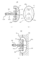
図1は、本実施形態の操作ボタン40を、その軸部の軸線と平行な面で切断した状態を示す端面図(a)、操作ボタン40の頭部を軸部の軸線方向に見た外面図(b)、操作ボタン40を形成するためのインサート成形の様子を示す概略端面図(c)である。
【0026】
操作ボタン40は、楕円状の平面形状を備えた頭部41と、この頭部41に対して一体化された支持板45と、この支持板45に対して接続固定された軸部42とから構成されている。軸部42には、図4(a)に示す操作ボタン10に形成された環状溝12a,12bと同様に用いられる環状溝42a,42bが形成されている。
【0027】
支持板45は、平面視楕円状の頭部41とほぼ相似形の平面形状(長手方向の端部が欠けた楕円状)を備えた板状体である。中央部には、上記軸部42を接続するための接続孔45aが形成され、この接続孔45aを中心にして図示上下方向に寄った位置にそれぞれ係合孔45b,45bが形成されている。
【0028】
本実施形態の場合、軸部42及び支持板45は、頭部41に作用する操作力を確実に受け取り、機器内部に向けて伝達するために高い剛性を備えた素材、例えばステンレス鋼等の金属材料であることが好ましい。一方、頭部41には、硬く冷たい感じを与えないように、或る程度柔らかな触感を有し、高級感を与えることができるような合成樹脂等の軟質材料やゴム等の弾性材料を用いることが好ましい。特に、ウレタン系樹脂や合成ゴムなどが柔らかな触感を操作者に与えるためには望ましい。
【0029】
本実施形態の操作ボタン40の製造方法は概略以下のとおりである。まず、軸部42を旋削加工等によって形成する。一方、支持板45を、金属板をプレス加工によって打ち抜くことによって形成する。次に、軸部42の先端部を支持板45の接続孔45a内に導入した状態で、カシメ加工、溶接、溶着又は接着等の接合処理を施して、軸部42と支持板45とを固着させる。その後、軸部42に固着された支持板45を図1(c)に示す型板51,52からなる金型50のキャビティ50A内に配置し、支持板45の係合孔45bに回転を防止するための位置決めピン53の先端部を挿入した状態とする。この状態で、図示しないゲートから溶融した合成樹脂を金型50のキャビティ50A内に注入する。このようにして、金型50内にて合成樹脂が固化すると、合成樹脂にて形成された頭部41と、支持板45とが一体化され、図1(a)に示す操作ボタン40が完成する。
【0030】
この操作ボタン40においては、頭部41が比較的柔らかな素材で構成されているので、ソフトな感触が得られ、高級感を感じることができる。また、頭部41が比較的柔らかくてもその背後に支持板45が取り付けられているので、頭部41の表面で受けた操作、例えば押圧力を、支持板45を介して確実に軸部42に伝達することができるので、頭部41が柔らかくても操作しにくくなることを防止できる。特に、平面形状が楕円状の頭部41に対して支持板45も類似の平面形状を備えているため、操作力が軸部42の軸線からずれた頭部外面位置に与えられても、支持板45が操作力を受け止めやすくなり、操作力を軸部42へと確実に伝達させることができる。
【0031】
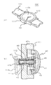
図2(a)は、本実施形態の操作ボタン40を組み込んだ腕時計100を示す概略斜視図であり、図2(b)は、腕時計100の操作ボタン40の組み込み部分の拡大断面図である。
【0032】
図2(a)に示すように、腕時計100は、時計本体110と時計バンド120とを有する。時計本体110には、時計ケース111の前面部に、透明なガラス板の内側に構成された文字板や指針等からなる時間情報表示部110Aが形成されている。また、時計ケース111の内部には、指針等を駆動する図示しないムーブメントが内蔵されている。時計ケース111の側部には、上述の操作ボタン40が取り付けられている。
【0033】
図2(b)に示すように、時計ケース111の側部に形成された貫通孔111aにパイプ状の案内部材112が接合され、この案内部材112の内部に上記操作ボタン40の軸部42が摺動可能に挿入されている。軸部42の上記環状溝42aには環状のパッキン46が装着され、このパッキン46は軸部42と案内部材112との間の密閉性を確保している。また、軸部の環状溝42bには止め輪47が装着され、この止め輪47は案内部材112の内端部に当接して操作ボタン40が時計ケース111から抜け出ないようにしている。
【0034】
操作ボタン40の軸部42の基部周りにはコイルバネ等からなる弾性部材48が配置され、この弾性部材48は、上記案内部材112(或いは時計ケース111)と、上記支持板45(或いは頭部41)との間において圧縮状態となっている。弾性部材48は常に操作ボタン40を時計ケース111の外側(図示右側)に押圧するようになっている。
【0035】
操作ボタン40の軸部42の内端部は、時計ケース111の内側に配置されたバネ材(金属板)等の接点部材113に当接可能に構成されている。操作ボタン40の頭部41を時計ケース111の外側から押圧すると、図示2点鎖線に示すように、弾性部材48の弾性力に抗して軸部42が案内部材112の内部を時計ケース111の内側へ向けて移動し、上記接点部材113を内側へ押圧するので、図示しない電気的接点が開閉動作する。接点部材113や電気的接点の構造は種々あるが、例えば、操作ボタン40の押圧によって接点部材113が押し込まれると、接点部材113の変形によって電気的接点が離反若しくは接触するように構成される。
【0036】
本実施形態においては、操作ボタン40の頭部41を軟質素材或いは弾性素材で構成することにより、頭部41を外部から押圧したときの触感を柔らかなものとすることができ、腕時計としての高級感を高めることができる。また、この場合、頭部41が比較的柔らかであっても、その背後に支持板45が配置されているので、頭部41への操作力を支持板45で受け、確実に軸部42に伝達することが可能になるので、確実に操作を行うことができる。さらに、頭部41の背後に支持板45を一体的に配置する構造としたことにより、頭部41の素材による触感を充分に得ることができるとともに支持板によって頭部の脱落を防止することも可能である。また、頭部にコーティングを行う場合に較べて、頭部41が磨滅しにくく耐久性を高めることができるので、高級感を損なうこともなくなる。
【0037】
一方、本実施形態においては、上記のような3体構造によって、個々の部分に対しては比較的容易に加工を施すことができるので製造コストの上昇を抑制できる。特に、軸部42と支持板45とを別体に構成することによってそれぞれを低コストで形成することが可能になる。
【0038】
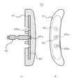
図3には、上記実施形態の操作ボタン40の変形例である操作ボタン60の構造を示す。図3(a)に示すように、この操作ボタン60においても、上記と同様に頭部61、軸部62及び支持板65を有する。軸部62と支持板65とは接続孔65aを介して相互に固着され、また、合成樹脂製(ゴムを含む。)の頭部61は支持板65と一体に成形されている。
【0039】
この操作ボタン60においては、頭部61が図示上下方向に引き伸ばされた延長形状を備えているとともに、図示上下方向に見て湾曲した異形状の平面形状を備えている。また、支持板65の平面形状は、頭部61の平面形状とほぼ対応した形状であり、図示上下方向に引き伸ばされた延長形状となっている。このように、操作ボタン60の頭部61が、軸部62の軸線に対して対称な形状(例えば当該軸線位置を中心とする円形)から大きく偏った平面形状を有するものである場合であって、頭部61が軟質素材で形成されており、しかも操作者が上記軸線位置からずれた位置にて頭部61を押圧操作するときでも、支持板65が頭部61の背後で支持しているので、確実に軸部62を押し込むことができる。
【0040】
尚、本発明の操作部品は、上述の図示例にのみ限定されるものではなく、本発明の要旨を逸脱しない範囲内において種々変更を加え得ることは勿論である。
【0041】
例えば、上記実施形態では、頭部を押圧操作する操作ボタンについて説明したが、操作部品としては上記操作ボタンに限らず、頭部を引き抜くように操作するもの、頭部の押圧及び引き抜きの双方の操作を行うもの、頭部を軸部の軸線方向とは異なる方向に移動させるもの(例えばトグルスイッチやスライドスイッチ)など、頭部を操作し、この操作を軸部へと伝えるものでさえあればよい。
【0042】
この場合、支持材は、実施形態のように頭部の背後に配置されている必要はなく、上記の操作態様に応じて頭部を支持できるように構成されていればよい。すなわち、頭部を操作した場合に、頭部に加わる操作力を支持材が受け止めることができるように構成されていればよい。
【0043】
また、上記実施形態では、頭部が支持板(支持材)に固定され、支持板(支持材)が軸部に固定されているが、例えば、頭部が軸部に固定され、支持板(支持材)もまた軸部に固定されているものであっても構わない。
【0044】
【発明の効果】
以上、説明したように本発明によれば、触感と操作性とを両立することのできる操作部品を実現できる。また、各部の構造を簡易に構成できるので、加工コストを低減できる。
【図面の簡単な説明】
【図1】本発明に係る操作部品の実施形態としての操作ボタンの構造を示す端面図(a)、頭部の平面図(b)及び操作ボタンを製造するためのインサート成形の様子を示す説明図(c)である。
【図2】同実施形態の操作ボタンを組み込んだ腕時計の概略斜視図(a)及び操作ボタンの組み込み部分を拡大して示す拡大端面図(b)である。
【図3】同実施形態の変形例の操作ボタンの端面図(a)及び頭部の平面図(b)である。
【図4】従来の操作ボタンの概略構造を示す端面図(a)〜(c)である。
【符号の説明】
40,50 操作ボタン
41,51 頭部
42,52 軸部
45,55 支持板
45a,55a 接続孔
46 パッキン
47 止め輪
48 弾性部材
100 腕時計
110 時計本体
111 時計ケース
112 案内部材
113 接点部材[0001]
BACKGROUND OF THE INVENTION
The present invention relates to an operation component, a manufacturing method thereof, and a device, and more particularly to a component structure suitable as a component constituting an operation button of a wristwatch or other devices.
[0002]
[Prior art]
Generally, an operation button or a crown attached to a side portion of a watch main body of a wristwatch includes a head formed so as to receive an operation and a shaft portion having a smaller cross section than the head. The shaft portion passes through the watch case and is introduced into the watch main body, and the inner end portion thereof is configured to contact a contact spring or the like.
[0003]
FIG. 4 is a schematic end view (a) to (c) schematically showing the shape of a conventional operation button. The
[0004]
The
[0005]
The
[0006]
[Problems to be solved by the invention]
However, when manufacturing the
[0007]
Further, the operation buttons and the crown are required to have good tactile sensation and reliable operability. However, since the
[0008]
Therefore, the present invention solves the above-described problems, and an object thereof is to provide a novel structure that can reduce the processing cost of operation parts such as operation buttons. Another object of the present invention is to provide a novel structure that can satisfy the tactile sensation, operability, and durability of the operation component at a high level.
[0009]
[Means for Solving the Problems]
In order to solve the above-described problems, an operation component according to the present invention is an operation component including a head for receiving an operation and a shaft extending behind the head for transmitting the operation. The support material is disposed so as to be able to support, the support material is coupled to the shaft portion, the head is made of a resin material, and the resin material is connected to the back via the side surface of the support material. It is characterized by wrapping around.
[0010]
According to this invention, by arranging the support material so that the head can be supported, the head can be supported by the support material at the time of operation. Even if it is made of an elastic material, it is possible to reliably transmit the operation applied to the head to the shaft portion by giving the support material sufficient rigidity. Can be achieved.
[0011]
Here, the head and the support member may be combined and the support member and the shaft portion may be combined, and the head and the shaft portion may be combined and the support member and The shaft portion may be connected to the shaft portion. That is, even if the head and the support member are not directly coupled, it is only necessary that the support member be arranged to support the head. In addition, as a coupling mode between the head and the shaft portion or the support material and the shaft portion, it is only necessary that the operation can be transmitted from the support material supporting the head to the shaft portion. It is not necessary to be fixed mechanically by attaching.
[0012]
In this invention, it is preferable that the support surface of the said support material which supports the said head is wider than the cross section of the said axial part. According to this means, since the support surface of the support member is wider than the cross section of the shaft portion, the head portion can be supported in a wide area, so that the head portion deviated from the axis line of the shaft portion is pressed. However, the operation on the head can be transmitted to the shaft more reliably, such as being operable without any problem.
[0013]
In the present invention, it is preferable that the support surface has a shape substantially similar to the planar shape of the head. Since the head is supported by a support surface having a shape substantially similar to the planar shape of the head, the planar shape of the head is an irregular shape with a low objectivity around the axis of the shaft (a planar shape different from the circle at the center of the axis) Even if it comprises, operation can be reliably transmitted to a shaft part via a support material.
[0014]
In this invention, it is preferable that the said support material has rigidity higher than the said head. According to this means, since the support material is higher in rigidity than the head, the head can be reliably supported, and the operation on the head is reliably received by the support material, and this is reliably received by the shaft portion. It becomes possible to communicate.
[0015]
In the present invention, the support material is preferably a plate-like body. According to this means, by forming the support material into a plate-like body, the support material can be easily formed by punching of the plate-like material such as press working, wire electric discharge machining, plate material stacking processing by NC milling, etc. Therefore, the processing cost can be reduced.
[0016]
In the present invention, it is preferable that the operation is a pressing operation on the head, and the support member is disposed behind the head. When a pressing operation is performed on the head, the supporting material supports the head from behind, so that the pressing operation exerted on the head is received by the supporting material and transmitted to the shaft portion. be able to.
[0017]
In the present invention, it is preferable that a connection hole is formed in the support member, and a tip end of the shaft member is inserted and fixed in the connection hole. According to this means, both can be reliably fixed without complicating the shapes of the shaft member and the support member.
[0018]
In this invention, it is preferable that the said axial part and the said support material are comprised with a metal material, and the said head is comprised with the resin material. According to this means, since the shaft portion and the support material are made of a metal material, it can be easily processed and sufficient rigidity can be secured, while the head portion is made of a resin material (soft resin, rubber, etc.). As a result, it is possible to obtain a soft and high-quality touch.
[0019]
Next, the manufacturing method of the operating component of the present invention is a manufacturing method of the operating component including a head for receiving an operation and a shaft portion extending behind the head to transmit the operation, A support member is connected to the shaft portion, and the support member is disposed so as to support the head portion.
[0020]
According to this means, the support member is connected to the shaft portion, and the support member is disposed so as to support the head portion, so that the shaft portion, the support material, and the head portion are separately processed and then connected to each other. Therefore, each part can be formed without using a complicated processing technique, the processing cost can be reduced, and an operation component that achieves both the feel of the head and the operability can be configured.
[0021]
In the present invention, it is preferable that the head is formed by injecting a molding material into the molding space in a state where the support material is disposed in the molding space. By arranging the support material in the molding space and molding the head, the head and the support material can be configured integrally, and even if the joint structure between the head and the support material is complex It can be formed easily, and the bondability between the head and the support material can be improved.
[0022]
In the present invention, the support material is preferably formed by punching a plate-like material. By forming the support material by punching a plate-like material, the processing cost can be further reduced. Here, the plate-like material may be a curved plate as well as a flat plate having a uniform thickness, and may have a wavy cross section.
[0023]
Another device according to the present invention uses the above-described operation component. An operation part is indispensable for the device, and by using the operation part of the present invention, it is possible to realize an operation unit that achieves both tactile feeling and operability. In particular, the present invention is preferably used for portable devices such as wristwatches, mobile phones, pagers, and portable information terminals.
[0024]
DETAILED DESCRIPTION OF THE INVENTION
Next, an embodiment of an operation component according to the present invention will be described in detail with reference to the accompanying drawings. The embodiment described below relates to an operation button attached to a side surface of a main body of a wristwatch. However, the present invention is not limited to the above-described operation buttons, but only includes a head that receives the operation and a shaft portion that transmits the operation, as well as a toggle switch and a slide switch in the wristwatch crown and other various electronic devices. It can be applied to various operation parts such as the operation part.
[0025]
FIG. 1 is an end view (a) showing a state in which the
[0026]
The
[0027]
The
[0028]
In the case of the present embodiment, the
[0029]
The manufacturing method of the
[0030]
In this
[0031]
FIG. 2A is a schematic perspective view showing the
[0032]
As shown in FIG. 2A, the
[0033]
As shown in FIG. 2 (b), a pipe-shaped
[0034]
An
[0035]
An inner end portion of the
[0036]
In the present embodiment, the
[0037]
On the other hand, in this embodiment, the above three-body structure can process each part relatively easily, so that an increase in manufacturing cost can be suppressed. In particular, it is possible to form the
[0038]
In FIG. 3, the structure of the
[0039]
The
[0040]
It should be noted that the operation component of the present invention is not limited to the illustrated example described above, and various modifications can be made without departing from the scope of the present invention.
[0041]
For example, in the above-described embodiment, the operation button for pressing the head has been described. However, the operation component is not limited to the operation button. Anything that operates the head and conveys this operation to the shaft, such as those that perform operations and those that move the head in a direction different from the axial direction of the shaft (for example, toggle switch and slide switch) Good.
[0042]
In this case, the support member does not need to be arranged behind the head as in the embodiment, and may be configured to support the head according to the operation mode described above. That is, it is only necessary that the support member can receive an operation force applied to the head when the head is operated.
[0043]
Moreover, in the said embodiment, although the head is fixed to the support plate (support material) and the support plate (support material) is being fixed to the axial part, for example, the head is fixed to the axial part and the support plate ( The support member may also be fixed to the shaft portion.
[0044]
【The invention's effect】
As described above, according to the present invention, it is possible to realize an operation component that can achieve both tactile sensation and operability. Moreover, since the structure of each part can be comprised simply, processing cost can be reduced.
[Brief description of the drawings]
FIG. 1 is an end view (a) showing a structure of an operation button as an embodiment of an operation part according to the present invention, a plan view (b) of a head, and an explanation showing a state of insert molding for manufacturing the operation button. It is a figure (c).
FIG. 2 is a schematic perspective view (a) of a wrist watch incorporating an operation button according to the embodiment and an enlarged end view (b) showing an enlarged portion of the operation button.
FIG. 3A is an end view of an operation button according to a modification of the embodiment, and FIG.
FIG. 4 is an end view (a) to (c) showing a schematic structure of a conventional operation button.
[Explanation of symbols]
40, 50
Claims (6)
前記頭部の背後を支持可能に支持材が配置され、該支持材が前記軸部に結合されており、
前記頭部は樹脂材料で構成されていると共に、この樹脂材料が前記支持材の側面を経由して背後に回り込んで構成されていることを特徴とする操作部品。In an operating component comprising a head for receiving an operation and a shaft extending behind the head to convey the operation,
A support material is disposed so as to support the back of the head, and the support material is coupled to the shaft portion,
The operating part is characterized in that the head is made of a resin material, and the resin material wraps around behind the side surface of the support material.
Priority Applications (1)
| Application Number | Priority Date | Filing Date | Title |
|---|---|---|---|
| JP2000376299A JP3729068B2 (en) | 2000-12-11 | 2000-12-11 | Operating parts, manufacturing method thereof and equipment |
Applications Claiming Priority (1)
| Application Number | Priority Date | Filing Date | Title |
|---|---|---|---|
| JP2000376299A JP3729068B2 (en) | 2000-12-11 | 2000-12-11 | Operating parts, manufacturing method thereof and equipment |
Publications (2)
| Publication Number | Publication Date |
|---|---|
| JP2002181957A JP2002181957A (en) | 2002-06-26 |
| JP3729068B2 true JP3729068B2 (en) | 2005-12-21 |
Family
ID=18845174
Family Applications (1)
| Application Number | Title | Priority Date | Filing Date |
|---|---|---|---|
| JP2000376299A Expired - Fee Related JP3729068B2 (en) | 2000-12-11 | 2000-12-11 | Operating parts, manufacturing method thereof and equipment |
Country Status (1)
| Country | Link |
|---|---|
| JP (1) | JP3729068B2 (en) |
Families Citing this family (1)
| Publication number | Priority date | Publication date | Assignee | Title |
|---|---|---|---|---|
| JP7121915B2 (en) * | 2020-12-01 | 2022-08-19 | カシオ計算機株式会社 | Switching device and clock |
-
2000
- 2000-12-11 JP JP2000376299A patent/JP3729068B2/en not_active Expired - Fee Related
Also Published As
| Publication number | Publication date |
|---|---|
| JP2002181957A (en) | 2002-06-26 |
Similar Documents
| Publication | Publication Date | Title |
|---|---|---|
| JP3931459B2 (en) | Band and wrist device | |
| US12228887B2 (en) | Case and timepiece | |
| JP2001289977A (en) | Means for loading data on portable article and extracting data from portable article such as particularly timepiece | |
| JP3729068B2 (en) | Operating parts, manufacturing method thereof and equipment | |
| CN219800115U (en) | Vibration feedback device, handheld communication device and wearable device | |
| CN113768255A (en) | Quick detach mechanism and wearable equipment | |
| CN210181405U (en) | Watch and watchband connecting structure thereof | |
| CN105869940B (en) | Electronic device | |
| JP2012199867A (en) | Portable wireless device | |
| CN218730540U (en) | Waterproof button | |
| JPH06253910A (en) | Manufacture of electrode conductor-containing band | |
| US7999204B2 (en) | Key frame and cover member for push button switch | |
| JPH11109057A (en) | External operation device, timepiece having external operation device, and electronic device having external operation device | |
| US20020009207A1 (en) | Connection method for microphone of mobile radio communication unit and connection structure thereof | |
| JP3849972B2 (en) | Cover member for pushbutton switch and manufacturing method thereof | |
| JP2003317579A (en) | Operation key | |
| CN223771000U (en) | A simplified speaker silicone button | |
| CN224083573U (en) | A protective case for electronic devices | |
| CN213212014U (en) | Key sheet fixing structure and remote controller applying same | |
| CN215117181U (en) | Watch shell assembly and watch | |
| CN102737867B (en) | Operation assembly | |
| JPH03186202A (en) | Band | |
| JP2022041046A (en) | Push switch | |
| JP2000292555A (en) | Structure of hour hand electronic watch | |
| JPH105014A (en) | Band and wrist-mounted equipment |
Legal Events
| Date | Code | Title | Description |
|---|---|---|---|
| A977 | Report on retrieval |
Free format text: JAPANESE INTERMEDIATE CODE: A971007 Effective date: 20050420 |
|
| A131 | Notification of reasons for refusal |
Free format text: JAPANESE INTERMEDIATE CODE: A131 Effective date: 20050510 |
|
| A521 | Written amendment |
Free format text: JAPANESE INTERMEDIATE CODE: A523 Effective date: 20050708 |
|
| TRDD | Decision of grant or rejection written | ||
| A01 | Written decision to grant a patent or to grant a registration (utility model) |
Free format text: JAPANESE INTERMEDIATE CODE: A01 Effective date: 20050913 |
|
| A61 | First payment of annual fees (during grant procedure) |
Free format text: JAPANESE INTERMEDIATE CODE: A61 Effective date: 20050926 |
|
| R150 | Certificate of patent or registration of utility model |
Free format text: JAPANESE INTERMEDIATE CODE: R150 |
|
| FPAY | Renewal fee payment (event date is renewal date of database) |
Free format text: PAYMENT UNTIL: 20091014 Year of fee payment: 4 |
|
| FPAY | Renewal fee payment (event date is renewal date of database) |
Free format text: PAYMENT UNTIL: 20101014 Year of fee payment: 5 |
|
| FPAY | Renewal fee payment (event date is renewal date of database) |
Free format text: PAYMENT UNTIL: 20101014 Year of fee payment: 5 |
|
| FPAY | Renewal fee payment (event date is renewal date of database) |
Free format text: PAYMENT UNTIL: 20111014 Year of fee payment: 6 |
|
| FPAY | Renewal fee payment (event date is renewal date of database) |
Free format text: PAYMENT UNTIL: 20121014 Year of fee payment: 7 |
|
| FPAY | Renewal fee payment (event date is renewal date of database) |
Free format text: PAYMENT UNTIL: 20121014 Year of fee payment: 7 |
|
| FPAY | Renewal fee payment (event date is renewal date of database) |
Free format text: PAYMENT UNTIL: 20131014 Year of fee payment: 8 |
|
| LAPS | Cancellation because of no payment of annual fees |