JP3729002B2 - Inkjet recording head - Google Patents
Inkjet recording head Download PDFInfo
- Publication number
- JP3729002B2 JP3729002B2 JP34635999A JP34635999A JP3729002B2 JP 3729002 B2 JP3729002 B2 JP 3729002B2 JP 34635999 A JP34635999 A JP 34635999A JP 34635999 A JP34635999 A JP 34635999A JP 3729002 B2 JP3729002 B2 JP 3729002B2
- Authority
- JP
- Japan
- Prior art keywords
- case
- recording head
- joint surface
- concave portion
- flow path
- Prior art date
- Legal status (The legal status is an assumption and is not a legal conclusion. Google has not performed a legal analysis and makes no representation as to the accuracy of the status listed.)
- Expired - Fee Related
Links
Images


Description
【0001】
【発明の属する技術分野】
本発明は、画像や文字等を記録紙に記録するためにノズル孔からインク滴を吐出するインクジェット式記録ヘッドに関する。
【0002】
【従来の技術】
記録装置として多用されているインクジェットプリンタは、印刷媒体(記録紙)にインク滴を着弾させることにより画像や文字等の印刷データを記録する構成であり、ノズル孔からインク滴を吐出するインクジェット式記録ヘッドを備える。
【0003】
このインクジェット式記録ヘッドは、インク滴を吐出するノズル孔を多数配列したノズルプレートを備え、このノズルプレートが記録紙に対向する状態でキャリッジに支持され、ガイド部材に沿って記録紙の幅方向に移動(主走査)させる。
【0004】
例えば、特開平6−320725号などの公報に開示されているように、インク滴の吐出駆動を圧電振動子により行う記録ヘッドでは、ノズルプレートはスペーサを介して振動板と貼り合わせされており、スペーサにはインクの流路及び圧力室となる空部を所定のパターンで形成し、気密性を保持するため一体化して流路ユニットとしている。そして、複数の圧電振動子を配列した振動子ユニットを、箱体状のケースに収めると共に、そのケースの先端面に流路ユニットを接合させ、このとき各ノズル孔に連なる各圧力室について各圧電振動子を対応させて接触状態としており、即ち、ケース先端面に形成した開口(窓)から各圧電振動子を臨ませて振動板に接触させており、各圧力室の振動板を振動させることで圧力変動を起こし、これによりインク滴を適宜に吐出させている。
【0005】
【発明が解決しようとする課題】
しかしながら、前記した従来のインクジェット式記録ヘッドでは、ケースの先端接合面に塗布(転写)した接着剤が流動性を持つことから、流路ユニットをケース側と接合させる際に、接合面上を接着剤が流動し、各圧電振動子を臨ませた開口へ流れ出てしまう接着剤のはみ出しがある。そして、この流れ出た接着剤は圧力室の弾性隔壁つまり振動板の弾性シートに付着して固まるので、振動板の撓み特性を変化させ、その結果、ノズル孔の並び列においてインクの吐出特性にバラツキを生じ、印刷品質を低下させるという問題があった。特に、カラー用の場合には、記録ヘッドはノズル孔を多数並べたノズル孔列を複数列並べ、しかも小形化のため隣り合うノズル孔列の間隔を狭めた構成を採っていることから、接着剤が流れ出す問題の影響が大きい。
【0006】
本発明は、上記した事情に鑑みなされたものであり、その目的は、流路ユニットとケースとの接合に際して、圧力室の一部を構成している振動板側への接着剤の流れ出しを低減させることができ、振動板の撓み特性を良好に保ち得て印刷品質の低下を防ぐことができるインクジェット式記録ヘッドを提供しようとするものである。
【0007】
【課題を解決するための手段】
本発明は上記した目的を達成するために提案されたものであり、請求項1に記載のものは、ノズル孔列を複数設けた流路ユニットと、この流路ユニットを接合する接合面に、ノズル孔列に対応した開口を複数有し、各開口に連通する収納空部を内部に形成したケースと、このケースの収納空部内に固定されて、先端の出力部を前記開口に臨ませた状態で、圧力室の一部を構成している振動板に接合した圧力発生手段と、を備え、この圧力発生手段の出力部により振動板を変位させてノズル孔から前記圧力室内のインクを吐出するインクジェット式記録ヘッドにおいて、前記ケースの複数の前記開口の間に位置するリブと前記流路ユニットとの接合面に形成された凹部と、前記凹部を大気開放させ、前記ケースと前記流路ユニットとの接合面とは反対側に延設された通気路と、を具備したことを特徴とするインクジェット式記録ヘッドである。
【0008】
請求項2に記載のものは、前記リブ部内に補強材をインサートし、前記凹部の幅を補強材の肉厚よりも狭く設定したことを特徴とする請求項1に記載のインクジェット式記録ヘッドである。
【0009】
請求項3に記載のものは、前記ケースの接合面にコンプライアンス用凹部を形成し、このコンプライアンス用凹部を大気開放し、接合面に、前記コンプライアンス用凹部と前記凹部とを連通する連絡路を形成したことを特徴とする請求項1又は2に記載のインクジェット式記録ヘッドである。
【0015】
【発明の実施の形態】
以下、本発明のインクジェット式記録ヘッドの実施形態を図面に基づいて説明する。図1から図4は、本発明にかかるインクジェット式記録ヘッド1(以下、記録ヘッド1という。)の一実施形態を示し、図1はその記録ヘッド1を一部分解して示す斜視図、図2はその記録ヘッド1を図1のYZ面で切断した断面図、図3は要部を拡大した断面図、図4はケースの接合面を説明する平面図である。
【0016】
このインクジェット式記録ヘッド1は、プラスチック製箱体状のケース2内に圧力発生手段として収容した圧電振動子3の駆動により、流路ユニット4の一部を構成しているノズルプレート5のノズル孔50からインク滴を吐出する構成となっている。
【0017】
流路ユニット4は、ノズルプレート5とスペーサ6と振動板7を貼り合わせて積層した構成とされ、スペーサ6にはインクの流路及び圧力室となる空部を所定のパターンで形成されていて、ノズルプレート5と振動板7とを上下に貼り合わせて一体化することで気密性を保持するようになっている。
【0018】
ノズルプレート5には、ドット形成密度に対応したピッチで複数のノズル孔50が列状に設けられている。本実施形態ではノズル孔50の列(ノズル孔列)が二列平行に設けられている。そして、これと対応してケース2には流路ユニット4との接合面に帯形状の細長い開口20が二つ平行に形成され、これら開口20から圧電振動子3の櫛歯状の先端が臨み、これら1本1本の先端(出力部)を振動板7の所定部(アイランド部)に接触させる構成となっている。
【0019】
スペーサ6は、シリコンウエハー等から形成されており、これをエッチング加工することにより各空部が所定パターンに区画されていて、図2及び図3に示すように、各ノズル孔50と連通する複数の圧力室60、共通インク室61、共通インク室61から各圧力室60へ繋がる複数のインク供給路62を構成する隔壁が適宜に形成されている。なお、共通インク室61には、振動板7に開設された接続口63を介してインク供給管8が接続され、インクカートリッジ(図示せず)に蓄えられたインクが供給される。
【0020】
振動板7は、図2に示すように、金属板としてのステンレス板7aにPPS膜等の弾性体膜(樹脂膜)7bを積層した二重構造を採り、各圧力室60に対応する部分はステンレス板側が環状にエッチング加工され、環内にアイランド部70が形成されており、各アイランド部70に各圧電振動子3の先端(出力部)を接合させるようになっている。
【0021】
圧電振動子3は、各圧力室60にそれぞれ対応して先端(出力部)が複数配列されており、これらは一枚の大きな圧電振動子に、所定ピッチで櫛歯状にスリット部を形成することにより構成され、その配列体の基部が固定板9に固定されて振動子ユニット39となっている。なお、図面に示す圧電振動子3は、充電されると圧電体と電極の積層方向とは直交する方向に収縮して振動板7を引っ張って圧力室60を膨張させ、放電すると伸長して振動板7を押圧することにより圧力室60を収縮させる。そして、圧力室60の膨張・収縮に伴う圧力室60内のインク圧力の変化を利用してノズル孔50からインク滴を吐出させる。
【0022】
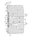
ケース2には、図2に示すように、振動子ユニット39を収容する収納空部21が形成されており、収納空部21は、流路ユニット4との接合面の開口20から反対側の面まで貫通しており、振動子ユニット39は圧電振動子3の先端を開口20から臨める姿勢で挿入され、各先端が開口20と面一となる位置で固定板9を収納空部21の内壁へ固着させることにより装着される。本実施形態では、収納空部21は二つに形成されており、両者の狭間にはリブ部22が設けられている。そして、ケース2の流路ユニット4との接合面には、図4に示すように、収納空部21の両開口21に挟まれた部位、即ちリブ部22の端面に凹部23が設けられ、また、開口20を挟んだ反対側の面上にコンプライアンス用凹部24が設けられている。
【0023】
凹部23は、本発明の主要構成となる窪み部であり、接着剤の塗布面積の減少を図ることにより接合時の接着剤のはみ出しを最小限に抑える目的で開口20に沿って細長い帯形状に形成されている。この凹部23には、図4に示すように、通気路としての連通管10が接続され、連通管10はケース2内をその基部へ向かって形成されており、その基部の側で管端部が大気開放している。したがって、凹部23は、接合面側の開口の開閉に拘らず、連通管10を介して常時大気圧になるような構成である。
【0024】
一方、コンプライアンス用の凹部24は、振動板7が容易に大きく変形することで大きなコンプライアンスが得られることを目的とする窪み部であり、これも開口20に沿って帯形状に形成されている。この様に、コンプライアンス用凹部24は、前記凹部23とは配置が異なるばかりでなく、目的、作用が異なるものである。
【0025】
以上の構成により本実施形態のインクジェット式記録ヘッド1は、ケース2と流路ユニット4との接合面に凹部23が設けられるので、その凹部23を設けた分は接合面積が減り、ケース2と流路ユニット4との接合に際して塗布(転写)する接着剤の量が減る。しかも、接合の際に凹部23へ流れ込む分もあるので、圧電振動子3の出力部が臨む開口20側へ流れ込んで振動板7、特に弾性体膜(弾性シート)7bに付着する接着剤の量を低減させることができる。また、連通管10を介して凹部23が大気開放されているので、流路ユニット4を接合した際に凹部23の開口が振動板7によって全面封止されても、凹部23内の圧力は大気圧を維持する。したがって、接合の際に凹部23の開口が塞がれても、接合面の余剰接着剤の一部が凹部23内に流れ込むことに何等支障もない。
【0026】
この様に、本実施形態では、凹部23によって接着剤の塗布面積を減少することと相俟って、従来はリブ部22の両側2ヶ所に流出していた余剰接着剤が凹部23の両側とリブ部22の両側との合計4ヶ所に分散して流れ出すことなり、開口20側を始めとする1ヶ所当たりの流れ出し量を著しく減少させることができる。したがって、流路ユニット4とケース2との接合に際して、圧力室60の弾性体膜への接着剤の流れ出しを低減させることができる。このため、振動板7の撓み特性を良好に保つことができ、これにより印刷品質の低下を防ぐことができる。
【0027】
なお、凹部23を大気開放する連通管10等の通気路は、接合面に交叉する方向にケース2の内部で延設し、接合面とは反対側のケース2の面やケース2の内部で管端部を開口することが好ましい。このように構成すると、ケース2側面に付着したインクがこの開口から通気路内に進入する虞れがあり、これを防止できるからである。すなわち、長期間使用すると、流路ユニット4やこの近傍のケース側面にインクミストが付着して溜り易く、このインクが記録ヘッド1の内部に進入することを防止する効果があり、接着信頼性が高まる。
【0028】
また、図5に示すように、通気路を接合面と平行に形成して管端部を接合面近傍のケース2側面に開口してもよい。この様に構成すると、通気路内にケース2側面に付着したインクが進入する可能性があるが、振動板7が通気路を覆う状態で接着されているので、開口20側などケース2内部に到達することはない。但し、接着境界がインクにさらされる部分が多くなるので、ケース2側面で開口するよりも、前記実施形態の様に、連通管10により他の部分で開口することが望ましい。
【0029】
図6は、本発明の第2実施形態を示し、記録ヘッド1のケース2を図4と同様に示す平面図である。第2実施形態では、リブ部22の端面に設けた凹部23には、別途連通管を接続しないで、代りに当該凹部23とコンプライアンス用の凹部24とを接続する連絡路25をケース2の接合面に設けており、コンプライアンス用の凹部24には、振動板7の弾性体膜の変形抵抗を減少させるために大気に繋がる連通路26が通気路として備えられているので、この連通路26と連絡路25を介して凹部23を大気開放する。この様に、第2実施形態では連通管10を別途設けることなく凹部23を大気開放できるので、第1実施形態と同様の作用、効果が得られる。
【0030】
図7は、本発明の第3実施形態を示し、記録ヘッド1のケース2を図4と同様に示す平面図である。第3実施形態は、開口20の間の接合面、すなわちリブ部22の端面に凹部23を形成しただけであり、凹部23への大気開放はないので凹部23内へ押し出される接着剤の量は第1,第2実施形態の場合よりも少ないことも考えられるが、凹部23を設けたことにより接着剤の塗布量が減り、開口20側へ流れ込む分量を従来よりも少ない量に抑えることが期待できる。
【0031】
図8は、本発明の第4実施形態を示し、記録ヘッド1のケース2を図4と同様に示す平面図である。第4実施形態では、開口20の間の接合面、すなわちリブ部22の端面に小さな凹部27を複数並べて設けており、それらの凹部27は流路ユニット4を接合することにより封止される構成を採っている。この場合、凹部27は小さいものの多数並べて設けられるので、ケース2の剛性を確保し易く、その一方で第3実施形態と同様な作用となり、同様の効果が得られる。
【0032】
そして、本実施形態の場合に、ケース2の接合面に接合する振動板7の板厚の一部に、図中一点鎖線で示すように、各凹部27に連通して一端がケース2側面に開口する大気開放用の溝65を形成して大気開放してもよい。振動板7に上記溝65を形成するには、振動板7が樹脂膜とステンレス板等の金属板との積層体で構成されているので、ステンレス板をエッチングして各凹部27に重なる部分を除去することにより所定幅の溝65を形成できる。ステンレス板等の金属板の板厚は、成形品であるケース2に凹部を形成する場合に比較して寸法の管理が容易であり、また、省スペースに寄与する。すなわち、接着剤の流れ出し量と大気開放の隙間を加えた体積が要求される体積となるが、射出成形品の一部として凹部を形成すると、その公差はエッチング加工の場合よりも大きくなるので、振動板7にエッチング加工して溝65を形成した方が必要面積が小さくて済み、省スペースに寄与する。
【0033】
図9は、本発明の第5実施形態を示し、記録ヘッド1を図2と同様に切断した断面図である。第5実施形態では、リブ部22内に金属板等の補強材11がインサートされており、リブ部22上に設けた凹部23の幅W1を、補強材11の厚みW2よりも狭く設定した構成を採る。この様に構成すると、凹部23の幅W1が補強材11の厚みW2よりも狭くなるので、凹部23を形成したリブ部22の端面近傍の剛性を確保し易く、これにより圧電振動子3を伸縮させた際に振動板7側からリブ部22へ作用する圧縮力を補強材11側へ確実に伝達させることができ、十分な強度を得られ、流路ユニット4の変形を有効に防止できる。したがって、リブ部22を薄くすることができ、記録ヘッド1のより一層の小型化を図れる。
【0034】
なお、圧力発生手段は、前記した圧電振動子3に限らず、例えば磁歪素子でもよい。また、ノズル列は、2列に限らず複数列であればよい。
【0035】
【発明の効果】
以上説明したように、本発明のインクジェット式記録ヘッドは、次に示す効果を奏する。請求項1の発明によれば、ケースの複数の開口の間に位置するリブと流路ユニットとの接合面に、凹部を形成するので、その凹部を設けた分だけ接合面積が減り、ケースと流路ユニットとの接合に際して塗布する接着剤の量が減る。このため、圧力発生手段の出力部が臨む開口へ流れ込む接着剤の量は低減し、しかも凹部へ流れ込む分もあるので、開口側へ流れ込む分量を一層少ない量に抑えることができる。したがって、流路ユニットとケースとの接合に際して、圧力室の振動板側への接着剤の流れ出しを低減させることができ、その結果、振動板の撓み特性を良好に保つことができる。これにより、振動板に付着した接着剤に起因する印刷品質の低下を防ぐことができる。
【0036】
請求項2の発明によれば、凹部が大気開放しているので、凹部の開口が流路ユニットによって塞がれても凹部内を大気圧に保つことができる。したがって、凹部内に接着剤を円滑に流れ込ませることができる。
【0037】
請求項3の発明によれば、一端が前記凹部に接続して該凹部を大気開放する通気路を、ケースの接合面に交叉する方向に延設したので、通気路の他端がケースの接合面から離れた部位で開口して大気開放する。したがって、長期間使用すると使用してインクが記録ヘッドの流路ユニット近傍に付着しても、この付着したインクが通気路を通って接着剤を浸透し、記録ヘッドの内部に進入することを防止できる。
【0038】
請求項4の発明によれば、収納空部同士の間に形成されるリブ部内に補強材をインサートし、前記凹部の幅を補強材の肉厚よりも狭く設定したので、リブ部の剛性、特にノズル孔列の中央部分近傍のリブ部の剛性を確保し易い。したがって、圧電振動子が収縮した際に作用するリブ部の圧縮力を確実に受け止めることができる。
【図面の簡単な説明】
【図1】インクジェット式記録ヘッドの一部を分解した斜視図である。
【図2】記録ヘッドを図1のYZ面で切断した断面図である。
【図3】要部を拡大した断面図である。
【図4】ケースの接合面を説明する平面図である。
【図5】通気路をケース側面に開口した実施形態の要部を示すケースの接合面の平面図である。
【図6】第2実施形態の要部を示すケースの接合面の平面図である。
【図7】第3実施形態を示すケースの接合面の平面図である。
【図8】第4実施形態を示すケースの接合面の平面図である。
【図9】リブ部内に補強材をインサートした第5実施形態を示す記録ヘッドの断面図である。
【符号の説明】
1 インクジェット式記録ヘッド
2 ケース
3 圧電振動子
4 流路ユニット
5 ノズルプレート
6 スペーサ
7 振動板
8 インク供給管
9 固定板
10 連通管
11 補強材
20 開口
21 収納空部
22 リブ部
23 凹部
24 コンプライアンス用の凹部
25 連絡路
26 連通路
27 凹部
39 振動子ユニット
50 ノズル孔
60 圧力室
61 共通インク室
62 インク供給路
63 接続口
65 溝
70 アイランド部[0001]
BACKGROUND OF THE INVENTION
The present invention relates to an ink jet recording head that ejects ink droplets from nozzle holes in order to record images, characters, and the like on recording paper.
[0002]
[Prior art]
Inkjet printers, which are widely used as recording devices, are configured to record print data such as images and characters by landing ink droplets on a print medium (recording paper). Inkjet recording that ejects ink droplets from nozzle holes A head is provided.
[0003]
The ink jet recording head includes a nozzle plate in which a large number of nozzle holes for ejecting ink droplets are arranged. The nozzle plate is supported by a carriage in a state of facing the recording paper, and extends in the width direction of the recording paper along the guide member. Move (main scan).
[0004]
For example, as disclosed in Japanese Patent Laid-Open No. 6-320725, in a recording head in which ink droplets are ejected by a piezoelectric vibrator, a nozzle plate is bonded to a vibration plate via a spacer. In the spacers, ink channels and pressure chambers are formed in a predetermined pattern, and are integrated into a channel unit to maintain airtightness. A vibrator unit in which a plurality of piezoelectric vibrators are arranged is housed in a box-shaped case, and a flow path unit is joined to the front end surface of the case. At this time, each piezoelectric chamber is connected to each nozzle hole. The vibrators are in contact with each other, that is, the piezoelectric vibrators are brought into contact with the diaphragm from the opening (window) formed on the front end surface of the case, and the diaphragm of each pressure chamber is vibrated. The pressure fluctuates in this way, thereby causing ink droplets to be appropriately discharged.
[0005]
[Problems to be solved by the invention]
However, in the above-described conventional ink jet recording head, the adhesive applied (transferred) to the joint surface at the tip of the case has fluidity. Therefore, when the flow path unit is joined to the case side, the adhesive surface is bonded. The adhesive flows and the adhesive protrudes into the opening facing each piezoelectric vibrator. Then, the adhesive that has flowed out adheres to the elastic partition of the pressure chamber, that is, the elastic sheet of the diaphragm, so that the bending characteristic of the diaphragm is changed, and as a result, the ink ejection characteristics vary in the array of nozzle holes. There is a problem that the printing quality is deteriorated. In particular, in the case of color printing, the recording head has a structure in which a plurality of nozzle hole arrays in which a large number of nozzle holes are arrayed are arranged, and the interval between adjacent nozzle hole arrays is reduced for miniaturization. The influence of the problem that the agent flows out is great.
[0006]
The present invention has been made in view of the above circumstances, and its purpose is to reduce the flow of adhesive to the diaphragm side constituting a part of the pressure chamber when the flow path unit and the case are joined. It is an object of the present invention to provide an ink jet recording head that can maintain a good bending characteristic of a vibration plate and can prevent deterioration in printing quality.
[0007]
[Means for Solving the Problems]
The present invention has been proposed in order to achieve the above-described object.In the first aspect of the present invention, a flow path unit provided with a plurality of nozzle hole arrays, and a joint surface for joining the flow path units, A case having a plurality of openings corresponding to the nozzle hole row, and a housing empty portion communicating with each opening formed therein, and the case is fixed in the housing empty portion of this case, and the output portion at the front end faces the opening. Pressure generating means joined to a diaphragm constituting a part of the pressure chamber in a state, and the diaphragm is displaced by an output portion of the pressure generating means to discharge ink in the pressure chamber from the nozzle hole. In the ink jet type recording head, a rib formed between a plurality of the openings of the case and a recess formed on a joint surface between the channel unit, the recess is opened to the atmosphere, and the case and the channel unit And the joint surface with An ink jet recording head is characterized by comprising a a ventilation passage which extends to the opposite side.
[0008]
According to a second aspect of the present invention, in the ink jet recording head according to the first aspect, a reinforcing material is inserted into the rib portion, and the width of the concave portion is set narrower than the thickness of the reinforcing material. is there.
[0009]
According to a third aspect of the present invention, a concave portion for compliance is formed on the joint surface of the case, the concave portion for compliance is opened to the atmosphere, and a communication path that communicates the concave portion for compliance and the concave portion is formed on the joint surface. The ink jet recording head according to claim 1, wherein the ink jet recording head is provided.
[0015]
DETAILED DESCRIPTION OF THE INVENTION
Hereinafter, embodiments of an ink jet recording head of the present invention will be described with reference to the drawings. 1 to 4 show an embodiment of an ink jet recording head 1 (hereinafter referred to as a recording head 1) according to the present invention. FIG. 1 is a perspective view showing the recording head 1 in a partially exploded view. FIG. 3 is a cross-sectional view of the recording head 1 cut along the YZ plane of FIG. 1, FIG. 3 is an enlarged cross-sectional view of the main part, and FIG. 4 is a plan view for explaining the joint surface of the case.
[0016]
The ink jet recording head 1 includes a nozzle hole in a nozzle plate 5 constituting a part of a flow path unit 4 by driving a
[0017]
The flow path unit 4 has a configuration in which a nozzle plate 5, a
[0018]
The nozzle plate 5 is provided with a plurality of
[0019]
The
[0020]
As shown in FIG. 2, the
[0021]
The
[0022]
As shown in FIG. 2, the
[0023]
The
[0024]
On the other hand, the compliance
[0025]
With the above configuration, the ink jet recording head 1 of the present embodiment is provided with the
[0026]
As described above, in the present embodiment, in combination with the reduction of the adhesive application area by the
[0027]
Note that the air passage such as the
[0028]
Further, as shown in FIG. 5, the air passage may be formed in parallel with the joint surface, and the pipe end may be opened on the side surface of the
[0029]
FIG. 6 shows a second embodiment of the present invention and is a plan view showing the
[0030]
FIG. 7 is a plan view showing the
[0031]
FIG. 8 shows a fourth embodiment of the present invention and is a plan view showing the
[0032]
In the case of the present embodiment, a part of the thickness of the
[0033]
FIG. 9 shows a fifth embodiment of the present invention and is a cross-sectional view of the recording head 1 cut in the same manner as in FIG. In the fifth embodiment, the reinforcing
[0034]
The pressure generating means is not limited to the
[0035]
【The invention's effect】
As described above, the ink jet recording head of the present invention has the following effects. According to the first aspect of the present invention, since the concave portion is formed in the joint surface between the rib and the flow path unit located between the plurality of openings of the case, the joint area is reduced by the amount of the concave portion, The amount of adhesive applied when joining with the flow path unit is reduced. For this reason, since the amount of the adhesive flowing into the opening facing the output portion of the pressure generating means is reduced, and there is also a portion flowing into the recess, the amount flowing into the opening side can be further reduced. Therefore, when the flow path unit and the case are joined, it is possible to reduce the flow of the adhesive to the diaphragm side of the pressure chamber, and as a result, it is possible to keep the flexure characteristics of the diaphragm favorable. Thereby, it is possible to prevent a decrease in print quality due to the adhesive adhered to the diaphragm.
[0036]
According to invention of
[0037]
According to the invention of
[0038]
According to the invention of claim 4, since the reinforcing material is inserted into the rib portion formed between the storage empty portions, and the width of the concave portion is set narrower than the thickness of the reinforcing material, the rigidity of the rib portion, In particular, it is easy to ensure the rigidity of the rib portion near the center portion of the nozzle hole row. Therefore, the compressive force of the rib portion that acts when the piezoelectric vibrator contracts can be reliably received.
[Brief description of the drawings]
FIG. 1 is an exploded perspective view of a part of an ink jet recording head.
FIG. 2 is a cross-sectional view of the recording head taken along the YZ plane of FIG.
FIG. 3 is an enlarged cross-sectional view of a main part.
FIG. 4 is a plan view for explaining a joint surface of the case.
FIG. 5 is a plan view of the joint surface of the case showing the main part of the embodiment in which the air passage is opened on the side surface of the case.
FIG. 6 is a plan view of a joint surface of a case showing the main part of the second embodiment.
FIG. 7 is a plan view of a joint surface of a case showing a third embodiment.
FIG. 8 is a plan view of a joint surface of a case showing a fourth embodiment.
FIG. 9 is a cross-sectional view of a recording head showing a fifth embodiment in which a reinforcing material is inserted in the rib portion.
[Explanation of symbols]
DESCRIPTION OF SYMBOLS 1
Claims (3)
この流路ユニットを接合する接合面に、ノズル孔列に対応した開口を複数有し、各開口に連通する収納空部を内部に形成したケースと、
このケースの収納空部内に固定されて、先端の出力部を前記開口に臨ませた状態で、圧力室の一部を構成している振動板に接合した圧力発生手段と、を備え、
この圧力発生手段の出力部により振動板を変位させてノズル孔から前記圧力室内のインクを吐出するインクジェット式記録ヘッドにおいて、
前記ケースの複数の前記開口の間に位置するリブと前記流路ユニットとの接合面に形成された凹部と、
前記凹部を大気開放させ、前記ケースと前記流路ユニットとの接合面とは反対側に延設された通気路と、を具備したことを特徴とするインクジェット式記録ヘッド。A flow path unit provided with a plurality of nozzle hole rows;
A case in which a plurality of openings corresponding to the nozzle hole rows are formed on the joint surface for joining the flow path units, and a housing empty portion communicating with each opening is formed inside,
A pressure generating means that is fixed in the housing empty portion of the case and is joined to a diaphragm constituting a part of the pressure chamber, with the output portion at the tip facing the opening;
In the ink jet recording head for discharging the ink in the pressure chamber from the nozzle hole by displacing the diaphragm by the output portion of the pressure generating means,
A recess formed on a joint surface between the rib and the flow path unit located between the plurality of openings of the case;
An ink jet recording head comprising: an air passage that opens the concave portion to the atmosphere and extends on a side opposite to a joint surface between the case and the flow path unit.
Priority Applications (1)
| Application Number | Priority Date | Filing Date | Title |
|---|---|---|---|
| JP34635999A JP3729002B2 (en) | 1999-12-06 | 1999-12-06 | Inkjet recording head |
Applications Claiming Priority (1)
| Application Number | Priority Date | Filing Date | Title |
|---|---|---|---|
| JP34635999A JP3729002B2 (en) | 1999-12-06 | 1999-12-06 | Inkjet recording head |
Publications (3)
| Publication Number | Publication Date |
|---|---|
| JP2001162792A JP2001162792A (en) | 2001-06-19 |
| JP2001162792A5 JP2001162792A5 (en) | 2004-08-19 |
| JP3729002B2 true JP3729002B2 (en) | 2005-12-21 |
Family
ID=18382887
Family Applications (1)
| Application Number | Title | Priority Date | Filing Date |
|---|---|---|---|
| JP34635999A Expired - Fee Related JP3729002B2 (en) | 1999-12-06 | 1999-12-06 | Inkjet recording head |
Country Status (1)
| Country | Link |
|---|---|
| JP (1) | JP3729002B2 (en) |
Families Citing this family (4)
| Publication number | Priority date | Publication date | Assignee | Title |
|---|---|---|---|---|
| JP4114333B2 (en) * | 2001-08-10 | 2008-07-09 | セイコーエプソン株式会社 | Inkjet recording head |
| JP5322719B2 (en) * | 2008-03-24 | 2013-10-23 | キヤノン株式会社 | Inkjet recording head |
| JP5685825B2 (en) * | 2010-03-26 | 2015-03-18 | セイコーエプソン株式会社 | Liquid ejecting head and liquid ejecting apparatus |
| JP5927761B2 (en) * | 2011-02-04 | 2016-06-01 | セイコーエプソン株式会社 | Liquid ejecting head, liquid ejecting apparatus, and method of manufacturing liquid ejecting head |
-
1999
- 1999-12-06 JP JP34635999A patent/JP3729002B2/en not_active Expired - Fee Related
Also Published As
| Publication number | Publication date |
|---|---|
| JP2001162792A (en) | 2001-06-19 |
Similar Documents
| Publication | Publication Date | Title |
|---|---|---|
| JP3687662B2 (en) | Liquid jet head | |
| US20020130930A1 (en) | Ink-jet recording head and ink-jet recording apparatus | |
| JPH07132597A (en) | Ink jet type recording head | |
| JP2002361868A (en) | Inkjet recording head and method of manufacturing the same | |
| JP3729002B2 (en) | Inkjet recording head | |
| JPH08150716A (en) | Ink jet recording head | |
| JP2004209655A (en) | Liquid injection head | |
| JPH0858086A (en) | Laminate type ink jet recording head | |
| JP3334752B2 (en) | Ink jet recording head | |
| JP2008221825A (en) | Liquid jetting head and liquid jetting device | |
| JP2007008108A (en) | Droplet discharging head | |
| JP2001113697A (en) | Ink-jet recording head | |
| JP3800317B2 (en) | Inkjet recording head and inkjet recording apparatus | |
| JP2006218776A (en) | Liquid injection head and liquid injection apparatus | |
| JP3589108B2 (en) | Ink jet recording head and ink jet recording apparatus | |
| JP3339288B2 (en) | Ink jet recording head | |
| US7387373B2 (en) | Liquid ejecting head and liquid ejecting apparatus | |
| JP3384305B2 (en) | Ink jet recording head | |
| JP2000263778A (en) | Actuator apparatus, ink jet recording head and ink jet recording apparatus | |
| JP3374877B2 (en) | Ink jet recording head | |
| JP3541869B2 (en) | Ink jet recording head | |
| JP3341911B2 (en) | Inkjet print head | |
| JP3484888B2 (en) | Ink jet recording head | |
| JP2003053968A (en) | Inkjet recording head | |
| JP2000296617A (en) | Ink jet recording head and ink jet recording apparatus |
Legal Events
| Date | Code | Title | Description |
|---|---|---|---|
| A977 | Report on retrieval |
Free format text: JAPANESE INTERMEDIATE CODE: A971007 Effective date: 20050128 |
|
| A131 | Notification of reasons for refusal |
Free format text: JAPANESE INTERMEDIATE CODE: A131 Effective date: 20050201 |
|
| A521 | Written amendment |
Free format text: JAPANESE INTERMEDIATE CODE: A523 Effective date: 20050401 |
|
| TRDD | Decision of grant or rejection written | ||
| A01 | Written decision to grant a patent or to grant a registration (utility model) |
Free format text: JAPANESE INTERMEDIATE CODE: A01 Effective date: 20050913 |
|
| A61 | First payment of annual fees (during grant procedure) |
Free format text: JAPANESE INTERMEDIATE CODE: A61 Effective date: 20050926 |
|
| R150 | Certificate of patent or registration of utility model |
Free format text: JAPANESE INTERMEDIATE CODE: R150 |
|
| FPAY | Renewal fee payment (event date is renewal date of database) |
Free format text: PAYMENT UNTIL: 20091014 Year of fee payment: 4 |
|
| FPAY | Renewal fee payment (event date is renewal date of database) |
Free format text: PAYMENT UNTIL: 20101014 Year of fee payment: 5 |
|
| FPAY | Renewal fee payment (event date is renewal date of database) |
Free format text: PAYMENT UNTIL: 20101014 Year of fee payment: 5 |
|
| FPAY | Renewal fee payment (event date is renewal date of database) |
Free format text: PAYMENT UNTIL: 20111014 Year of fee payment: 6 |
|
| FPAY | Renewal fee payment (event date is renewal date of database) |
Free format text: PAYMENT UNTIL: 20121014 Year of fee payment: 7 |
|
| FPAY | Renewal fee payment (event date is renewal date of database) |
Free format text: PAYMENT UNTIL: 20121014 Year of fee payment: 7 |
|
| FPAY | Renewal fee payment (event date is renewal date of database) |
Free format text: PAYMENT UNTIL: 20131014 Year of fee payment: 8 |
|
| S531 | Written request for registration of change of domicile |
Free format text: JAPANESE INTERMEDIATE CODE: R313531 |
|
| R350 | Written notification of registration of transfer |
Free format text: JAPANESE INTERMEDIATE CODE: R350 |
|
| LAPS | Cancellation because of no payment of annual fees |